Ford Mondeo (petrol engines). Manual - part 31
 

  Index      Ford     Ford Mondeo - service and repair manual (petrol engines)


Search            


Content   ..  29  30  31  32   ..


Ford Mondeo (petrol engines). Manual - part 31


Support the caliper in one hand, and
prevent the hydraulic hose from turning with
the other hand. Unscrew the caliper from the
hose, making sure that the hose is not twisted
unduly or strained. Once the caliper is
detached, plug the open hydraulic unions in
the caliper and hose, to keep out dust and
dirt.
If required, the caliper carrier bracket can
be unbolted and removed from the steering
knuckle (see illustration).

Overhaul

With the caliper on the bench, brush away
all traces of dust and dirt, but take care not to
inhale any dust, as it may be injurious to
health.
Pull the dust-excluding rubber seal from the
end of the piston.
Apply low air pressure to the fluid inlet
union, and eject the piston. Only low air
pressure is required for this, such as is
produced by a foot-operated tyre pump.

Caution: The piston may be
ejected with some force.

10 Using a suitable blunt instrument (for
instance a knitting needle or a crochet hook),
prise the piston seal from the groove in the
cylinder bore. Take care not to scratch the
surface of the bore.
11 Clean the piston and caliper body with
methylated spirit, and allow to dry. Examine the
surfaces of the piston and cylinder bore for wear,
damage and corrosion. If the piston alone is
unserviceable, a new piston must be obtained,
along with seals. If the cylinder bore is
unserviceable, the complete caliper must be
renewed. The seals must be renewed, regardless
of the condition of the other components.
12 Coat the piston and seals with clean
brake fluid, then manipulate the piston seal
into the groove in the cylinder bore.

13 Push the piston squarely into its bore.
14 Fit the dust-excluding rubber seal onto
the piston and caliper, then depress the
piston fully.

Refitting

15 Refit the caliper, and where applicable the
carrier bracket, by reversing the removal
operations. Make sure that the flexible brake
hose is not twisted. Tighten the mounting
bolts and wheel nuts to the specified torque
(see illustration).
16 Bleed the brake circuit according to the
procedure given in Section 15, remembering
to remove the brake hose clamp from the
flexible hose. Make sure there are no leaks
from the hose connections. Test the brakes
carefully before returning the vehicle to
normal service.

Note: To prevent uneven braking, BOTH front
brake discs should be renewed or reground at
the same time.

Inspection

Apply the handbrake. Loosen the relevant
wheel nuts, jack up the front of the vehicle
and support it on axle stands. Remove the
wheel.
Remove the front brake caliper and carrier
bracket with reference to Section 3, but do
not disconnect the flexible hose. Support the
caliper on an axle stand, or suspend it out of
the way with a piece of wire, taking care to
avoid straining the flexible hose.
Temporarily refit two of the wheel nuts to
diagonally-opposite studs, with the flat sides
of the nuts against the disc. Tighten the nuts
progressively, to hold the disc firmly.
Scrape any corrosion from the disc. Rotate
the disc, and examine it for deep scoring,
grooving or cracks. Using a micrometer,
measure the thickness of the disc in several
places. The minimum thickness is stamped on
the disc hub (see illustrations). Light wear
and scoring is normal, but if excessive, the

disc should be removed, and either reground
by a specialist, or renewed. If regrinding is
undertaken, the minimum thickness must be
maintained. Obviously, if the disc is cracked,
it must be renewed.
Using a dial gauge or a flat metal block and
feeler gauges, check that the disc run-out 
10 mm from the outer edge does not exceed
the limit given in the Specifications. To do
this, fix the measuring equipment, and rotate
the disc, noting the variation in measurement
as the disc is rotated (see illustration). The
difference between the minimum and
maximum measurements recorded is the disc
run-out.
If the run-out is greater than the specified
amount, check for variations of the disc
thickness as follows. Mark the disc at eight
positions 45° apart, then using a micrometer,
measure the disc thickness at the eight
positions, 15 mm in from the outer edge. If the
variation between the minimum and maximum
readings is greater than the specified amount,
the disc should be renewed.
The hub face run-out can also be checked
in a similar way. First remove the disc as
described later in this Section, fix the
measuring equipment, then slowly rotate the
hub, and check that the run-out does not
exceed the amount given in the
Specifications. If the hub face run-out is
excessive, this should be corrected (by
renewing the hub bearings - see Chapter 10)
before rechecking the disc run-out.

4 Front brake disc - inspection,

removal and refitting

Braking system  9•5

9

4.5  Measuring the disc run-out with a dial

gauge

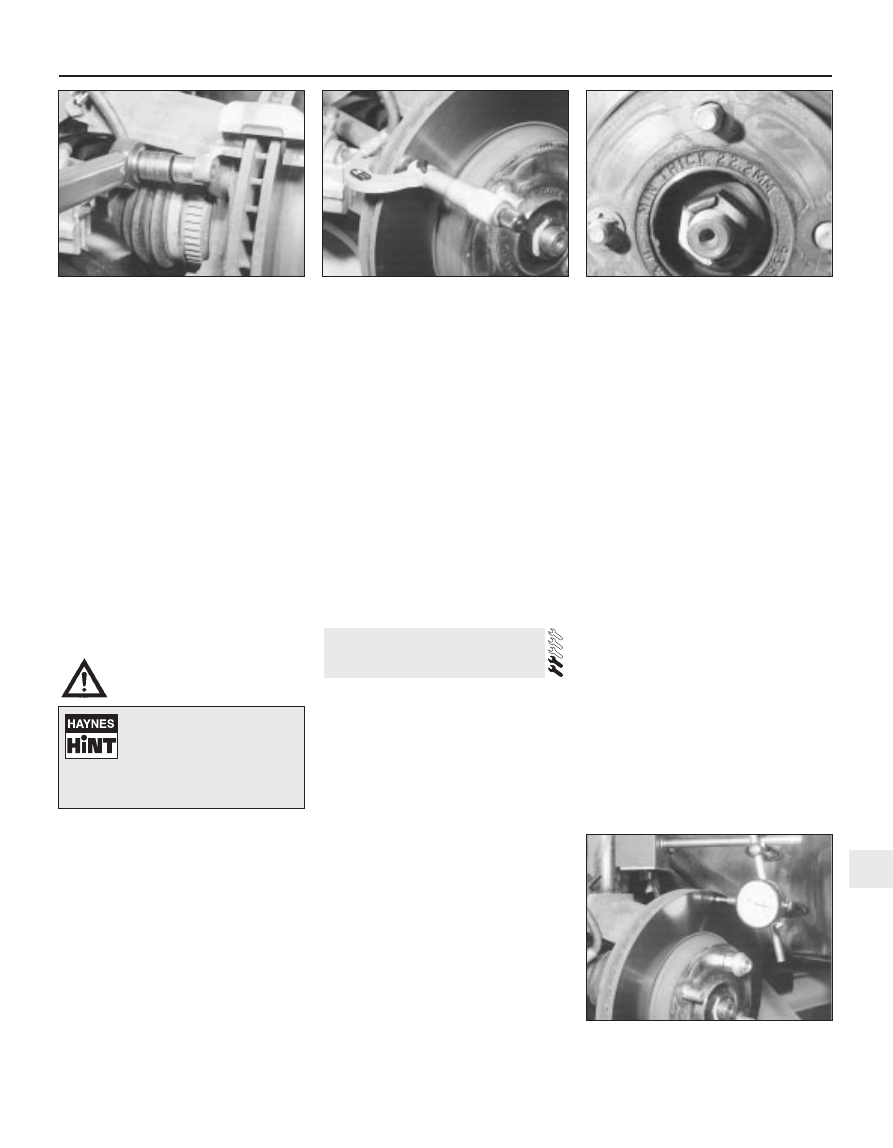
3.15  Tightening the carrier bracket

mounting bolts

4.4A  Using a micrometer to measure the

thickness of the front brake disc

4.4B  Disc minimum thickness marking

Position a thin piece of wood
between the piston and the
caliper body, to prevent
damage to the end face of the

piston, in the event of it being ejected
suddenly.

Removal

With the wheel and caliper removed,
remove the wheel nuts which were
temporarily refitted in paragraph 3.
Mark the disc in relation to the hub, if it is to
be refitted.
10 Remove the two special washers (where
fitted), and withdraw the disc over the wheel
studs (see illustrations).

Refitting

11 Make sure that the disc and hub mating
surfaces are clean, then locate the disc on the
wheel studs. Align the previously-made marks
if the original disc is being refitted.
12 Refit the two special washers, where
fitted.
13 Refit the brake caliper and carrier bracket
with reference to Section 3.
14 Refit the wheel, and lower the vehicle to
the ground.
15 Test the brakes carefully before returning
the vehicle to normal service.

Note: To prevent uneven braking, BOTH rear
brake drums should be renewed at the same
time.

Removal

Chock the front wheels, release the
handbrake and engage 1st gear (or “P”).

Loosen the relevant wheel nuts, jack up the
rear of the vehicle and support it on axle
stands. Remove the wheel.
Remove the two special clips (where fitted),
and withdraw the brake drum over the wheel
studs. If the drum will not pass over the
shoes, it is possible to release the automatic
adjuster mechanism by prising out the small
rubber grommet near the centre of the
backplate, and inserting a screwdriver
through the small hole. The self-adjusting
ratchet can then be rotated, so that the brake
shoes move to their lowest setting (see
illustrations)
. Refit the rubber grommet
before proceeding.
With the brake drum removed, clean the
dust from the drum, brake shoes, wheel
cylinder and backplate, using brake cleaner or
methylated spirit. Take care not to inhale the
dust, as it may contain asbestos.

Inspection

Clean the inside surfaces of the brake
drum, then examine the internal friction
surface for signs of scoring or cracks. If it is
cracked, deeply scored, or has worn to a
diameter greater than the maximum given in
the Specifications, then it should be renewed,
together with the drum on the other side.
Regrinding of the brake drum is not
recommended.

Refitting

Locate the brake drum over the wheel
studs, and (where fitted) refit the special clips.

Make sure that the drum contacts the hub
flange.
Refit the wheel, then check the remaining
rear drum.
Lower the vehicle to the ground, and
tighten the wheel nuts to the specified torque.
Depress the brake pedal several times, in
order to operate the self-adjusting mechanism
and set the shoes at their normal operating
position.
Test the brakes carefully before returning
the vehicle to normal service.

Warning: Drum brake shoes must
be renewed on both rear wheels
at the same time - never renew
the shoes on only one wheel, as

uneven braking may result. Also, the dust
created by wear of the shoes may contain
asbestos, which is a health hazard. Never
blow it out with compressed air, and don’t
inhale any of it. An approved filtering mask
should be worn when working on the
brakes. DO NOT use petroleum-based
solvents to clean brake parts; use brake
cleaner or methylated spirit only.
Remove the rear brake drums as described
in Section 5. Work on one brake assembly at a
time, using the assembled brake for reference
if necessary.
Follow the accompanying illustrations for
the brake shoe renewal procedure (see
illustrations 6.2A to 6.2O). Be sure to stay in
order, and read the caption under each
illustration.
If the wheel cylinder shows signs of fluid
leakage, or if there is any reason to suspect it
of being defective, inspect it now, as
described in the next Section.
Fit the new brake shoes using a reversal of
the removal procedure, but set the eccentric
cam at its lowest position before assembling it
to the trailing shoe.
Before refitting the brake drum, it should be
checked as described in Section 5.

6 Rear brake shoes - renewal

5 Rear brake drum - removal,

inspection and refitting

9•6 Braking system

4.10A  Remove the special washers . . .

4.10B  . . . and withdraw the disc

5.2A  Releasing the automatic adjuster

mechanism with a screwdriver inserted

through the small hole in the backplate

5.2B  Removing a rear brake drum

6.2A  Note the fitted position of the springs

and the adjuster strut, then clean the

components with brake cleaner, and allow

to dry. Position a tray beneath the

backplate, to catch the fluid and residue

Braking system  9•7

9

6.2K  Pull the handbrake cable spring back

from the operating lever on the rear of the

trailing shoe. Unhook the cable end from the

cut-out in the lever, and remove the shoe

6.2L  Unhook the automatic adjustment

strut from the trailing brake shoe . . .

6.2M  . . . and remove the small spring

6.2B  Remove the two shoe hold-down

springs, using a pair of pliers to depress

the upper ends so that they can be

withdrawn downwards off the pins

6.2C  Remove the hold-down pins from the

backplate

6.2D  Pull the bottom end of the leading

(front) brake shoe from the bottom anchor

(use pliers or an adjustable spanner over

the edge of the shoe to lever it away)

6.2E  Release the trailing (rear) brake shoe

from the anchor, then move the bottom
ends of both shoes towards each other

6.2F  Unhook the lower return spring from

the shoes, noting the location holes

6.2G  Move the bottom ends of the brake

shoes together, and disconnect the top

ends of the shoes from the wheel cylinder,

taking care not to damage the rubber boots

6.2H  Unhook the upper return spring from

the shoes . . .

6.2I  . . . and withdraw the leading shoe

from the backplate

6.2J  To prevent the wheel cylinder pistons

from being accidentally ejected, fit a

suitable elastic band or wire lengthwise

over the cylinder/pistons. Don’t press the
brake pedal while the shoes are removed

With the drum in position, refit the wheel,
then carry out the renewal procedure on the
remaining rear brake.
Lower the vehicle to the ground, and
tighten the wheel nuts.
Depress the brake pedal several times, in
order to operate the self-adjusting mechanism
and set the shoes at their normal operating
position.
Make several forward and reverse stops,
and operate the handbrake fully two or three
times. Give the vehicle a road test, to make
sure that the brakes are functioning correctly,
and to bed-in the new linings to the contours
of the disc. Remember that the new linings
will not give full braking efficiency until they
have bedded-in.

Note: Before starting work, check on the
availability of parts (overhaul kit of seals). Also
bear in mind that if the brake shoes have been
contaminated by fluid leaking from the wheel
cylinder, they must be renewed. In principle,
the shoes on BOTH sides of the vehicle must
be renewed, even if they are only
contaminated on one side.

Removal

Remove the brake drum as described in
Section 5.
Minimise fluid loss either by removing the
master cylinder reservoir cap, and then
tightening it down onto a piece of polythene
to obtain an airtight seal, or by using a brake
hose clamp, a G-clamp, or similar tool, to
clamp the flexible hose at the nearest
convenient point to the wheel cylinder.
Pull the brake shoes apart at their top ends,
so that they are just clear of the wheel
cylinder. The automatic adjuster will hold the
shoes in this position, so that the cylinder can
be withdrawn.
Wipe away all traces of dirt around the
hydraulic union at the rear of the wheel
cylinder, then undo the union nut.

Unscrew the two bolts securing the wheel
cylinder to the backplate (see illustration).
Withdraw the wheel cylinder from the
backplate so that it is clear of the brake
shoes. Plug the open hydraulic unions, to
prevent the entry of dirt, and to minimise
further fluid loss whilst the cylinder is
detached.

Overhaul

Clean the external surfaces of the cylinder,
and unscrew the bleed screw.
Carefully prise off the dust cover from each
end of the cylinder.
Tap the wheel cylinder on a block of wood
to eject the pistons and seals, keeping them
identified for location. Finally remove the
spring.
10 Clean the pistons and the cylinder by
washing in methylated spirit or fresh hydraulic
fluid. Do not use petrol, paraffin or any other
mineral-based fluid. Remove and discard the
old seals, noting which way round they are
fitted.
11 Examine the surfaces of the pistons and
the cylinder bores, and look for any signs of
rust or scoring. If such damage is evident, the
complete wheel cylinder must be renewed.
12 Reassemble by lubricating the first piston
in clean hydraulic fluid, then manipulating a
new seal into position, so that its raised lip
faces away from the brake shoe bearing face
of the piston.
13 Insert the piston into the cylinder. As the
seal enters the bore, twist the piston back and
forth so that the seal lip is not trapped.
14 Insert the spring, then refit the remaining
piston and seal, again making sure that the
seal lip is not trapped as it enters the bore.
15 Fit new dust covers to the grooves in the
pistons and wheel cylinder body.
16 Refit the bleed screw.

Refitting

17 Wipe clean the backplate, and remove the
plug from the end of the hydraulic pipe. Fit the
cylinder onto the backplate, and screw in the
hydraulic union nut by hand, being careful not
to cross-thread it.

18 Tighten the mounting bolts, then fully
tighten the hydraulic union nut.
19 Retract the automatic brake adjuster
mechanism, so that the brake shoes engage
with the pistons of the wheel cylinder. To do
this, prise the shoes apart slightly, turn the
automatic adjuster to its minimum position,
and release the shoes.
20 Remove the clamp from the flexible brake
hose, or the polythene from the master
cylinder (as applicable).
21 Refit the brake drum with reference to
Section 5.
22 Bleed the brake hydraulic system as
described in Section 15. Providing suitable
precautions were taken to minimise loss of
fluid, it should only be necessary to bleed the
relevant rear brake.
23 Test the brakes carefully before returning
the vehicle to normal service.

Warning: Disc brake pads must
be renewed on BOTH rear wheels
at the same time - never renew
the pads on only one wheel, as

uneven braking may result. Although
genuine Ford linings are asbestos-free, the
dust created by wear of non-genuine pads
may contain asbestos, which is a health
hazard. Never blow it out with compressed
air, and don’t inhale any of it. DO NOT use
petroleum-based solvents to clean brake
parts; use brake cleaner or methylated
spirit only. DO NOT allow any brake fluid,
oil or grease to contact the brake pads or
disc.

Chock the front wheels, and engage 1st
gear (or “P”). Loosen the rear wheel nuts, jack
up the rear of the vehicle and support it on
axle stands.
Remove the rear wheels. Work on one
brake assembly at a time, using the
assembled brake for reference if necessary.
Inspect the rear brake disc as described in
Section 10.
Extract the spring clip, and pull out the
retaining pin securing the caliper to the carrier

8 Rear brake pads - renewal

7 Rear wheel cylinder 

removal, overhaul and refitting

9•8 Braking system

6.2N  Clean the backplate, and apply small

amounts of high-melting-point brake

grease to the brake shoe contact points.

Be careful not to get grease on any friction

surfaces

6.2O  Lubricate the sliding components of

the automatic adjuster with a little high-

melting-point brake grease, but leave the

serrations on the eccentric cam shown

here clean

7.5  Bolts securing the wheel cylinder to

the backplate. Hydraulic union nut and

bleed screw cover are also visible


Content   ..  29  30  31  32   ..