Ford Mondeo (petrol engines). Manual - part 30
 

  Index      Ford     Ford Mondeo - service and repair manual (petrol engines)


Search            


Content   ..  28  29  30  31   ..


Ford Mondeo (petrol engines). Manual - part 30


Chapter 9 Braking system

ABS hydraulic unit - removal and refitting  . . . . . . . . . . . . . . . . . . . . 20
ABS relay box - removal and refitting  . . . . . . . . . . . . . . . . . . . . . . . . 22
ABS wheel sensor - testing, removal and refitting  . . . . . . . . . . . . . . 21
Brake check  . . . . . . . . . . . . . . . . . . . . . . . . . . . . . . . . .

See Chapter 1

Brake fluid renewal . . . . . . . . . . . . . . . . . . . . . . . . . . . .

See Chapter 1

Brake pedal - removal and refitting . . . . . . . . . . . . . . . . . . . . . . . . . . 12
Brake pedal-to-servo cross-link (right-hand-drive models 

only) - removal and refitting . . . . . . . . . . . . . . . . . . . . . . . . . . . . . . 13

Front brake caliper - removal, overhaul and refitting  . . . . . . . . . . . .

3

Front brake disc - inspection, removal and refitting  . . . . . . . . . . . . .

4

Front brake pads - renewal  . . . . . . . . . . . . . . . . . . . . . . . . . . . . . . . .

2

General information . . . . . . . . . . . . . . . . . . . . . . . . . . . . . . . . . . . . . .

1

Handbrake cables - removal and refitting . . . . . . . . . . . . . . . . . . . . . 27
Handbrake lever - removal and refitting  . . . . . . . . . . . . . . . . . . . . . . 26
Hydraulic pipes and hoses - inspection, removal and refitting  . . . . . 14
Hydraulic system - bleeding  . . . . . . . . . . . . . . . . . . . . . . . . . . . . . . . 15

Master cylinder - removal and refitting  . . . . . . . . . . . . . . . . . . . . . . . 11
Pressure-control relief valve (ABS models) - removal and refitting . . 19
Pressure-control relief valve (non-ABS models) - removal 

and refitting  . . . . . . . . . . . . . . . . . . . . . . . . . . . . . . . . . . . . . . . . . . 18

Rear brake caliper - removal, overhaul and refitting  . . . . . . . . . . . . .

9

Rear brake disc - inspection, removal and refitting  . . . . . . . . . . . . . 10
Rear brake drum - removal, inspection and refitting . . . . . . . . . . . . .

5

Rear brake pads - renewal  . . . . . . . . . . . . . . . . . . . . . . . . . . . . . . . .

8

Rear brake shoes - renewal  . . . . . . . . . . . . . . . . . . . . . . . . . . . . . . .

6

Rear wheel cylinder - removal, overhaul and refitting  . . . . . . . . . . . .

7

Stop-light switch - removal, refitting and adjustment  . . . . . . . . . . . . 25
TCS inhibitor switch - removal and refitting  . . . . . . . . . . . . . . . . . . . 23
TCS throttle actuator - removal and refitting  . . . . . . . . . . . . . . . . . . 24
Vacuum servo unit - testing, removal and refitting  . . . . . . . . . . . . . . 16
Vacuum servo unit vacuum hose and non-return valve - 

removal, testing and refitting . . . . . . . . . . . . . . . . . . . . . . . . . . . . . 17

Front brakes

Type  . . . . . . . . . . . . . . . . . . . . . . . . . . . . . . . . . . . . . . . . . . . . . . . . . . . .

Ventilated disc, with single-piston floating caliper

Disc diameter  . . . . . . . . . . . . . . . . . . . . . . . . . . . . . . . . . . . . . . . . . . . . .

260.0 mm

Disc thickness:

New  . . . . . . . . . . . . . . . . . . . . . . . . . . . . . . . . . . . . . . . . . . . . . . . . . . .

24.15 mm

Minimum  . . . . . . . . . . . . . . . . . . . . . . . . . . . . . . . . . . . . . . . . . . . . . . .

22.20 mm

Maximum disc run-out (fitted)  . . . . . . . . . . . . . . . . . . . . . . . . . . . . . . . . .

0.15 mm

Maximum disc thickness variation  . . . . . . . . . . . . . . . . . . . . . . . . . . . . .

0.015 mm

Front hub face maximum run-out  . . . . . . . . . . . . . . . . . . . . . . . . . . . . . .

0.05 mm

Rear drum brakes

Type  . . . . . . . . . . . . . . . . . . . . . . . . . . . . . . . . . . . . . . . . . . . . . . . . . . . .

Leading and trailing shoes, with automatic adjusters

Drum diameter:

New:

1.6 Saloon/Hatchback . . . . . . . . . . . . . . . . . . . . . . . . . . . . . . . . . . .

203.0 mm

1.8 and 2.0 Saloon/Hatchback  . . . . . . . . . . . . . . . . . . . . . . . . . . . .

228.6 mm

Estate . . . . . . . . . . . . . . . . . . . . . . . . . . . . . . . . . . . . . . . . . . . . . . . .

228.6 mm

Maximum diameter:

1.6 Saloon/Hatchback . . . . . . . . . . . . . . . . . . . . . . . . . . . . . . . . . . .

204.2 mm

1.8 and 2.0 Saloon/Hatchback  . . . . . . . . . . . . . . . . . . . . . . . . . . . .

229.6 mm

Estate . . . . . . . . . . . . . . . . . . . . . . . . . . . . . . . . . . . . . . . . . . . . . . . .

229.6 mm

Rear disc brakes

Type  . . . . . . . . . . . . . . . . . . . . . . . . . . . . . . . . . . . . . . . . . . . . . . . . . . . .

Solid disc, with single-piston floating caliper

Disc diameter  . . . . . . . . . . . . . . . . . . . . . . . . . . . . . . . . . . . . . . . . . . . . .

252.0 mm

Disc thickness:

New  . . . . . . . . . . . . . . . . . . . . . . . . . . . . . . . . . . . . . . . . . . . . . . . . . . .

20.0 mm

Minimum  . . . . . . . . . . . . . . . . . . . . . . . . . . . . . . . . . . . . . . . . . . . . . . .

18.0 mm

Maximum disc run-out (fitted)  . . . . . . . . . . . . . . . . . . . . . . . . . . . . . . . . .

0.15 mm

Maximum disc thickness variation  . . . . . . . . . . . . . . . . . . . . . . . . . . . . .

0.015 mm

Rear hub face maximum run-out  . . . . . . . . . . . . . . . . . . . . . . . . . . . . . .

0.05 mm

9•1

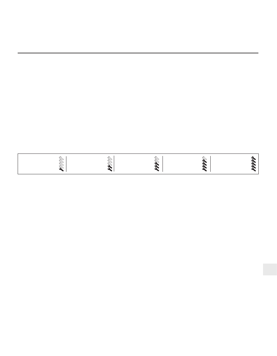
Easy, suitable for
novice with little
experience

Fairly easy, suitable
for beginner with
some experience

Fairly difficult, suitable
for competent DIY
mechanic

Difficult, suitable for
experienced  DIY
mechanic

Very difficult,
suitable for expert DIY
or  professional

Degrees of difficulty

Specifications

Contents

9

Torque wrench settings

Nm

lbf ft

Front caliper bracket  . . . . . . . . . . . . . . . . . . . . . . . . . . . . . . . . . . . . . . . .

120

89

Rear caliper bracket  . . . . . . . . . . . . . . . . . . . . . . . . . . . . . . . . . . . . . . . .

59

44

Front caliper guide bolts  . . . . . . . . . . . . . . . . . . . . . . . . . . . . . . . . . . . . .

28

21

Rear caliper guide bolts  . . . . . . . . . . . . . . . . . . . . . . . . . . . . . . . . . . . . .

41

30

Rear drum brake backplate . . . . . . . . . . . . . . . . . . . . . . . . . . . . . . . . . . .

50

37

Vacuum servo unit  . . . . . . . . . . . . . . . . . . . . . . . . . . . . . . . . . . . . . . . . .

40

30

Master cylinder  . . . . . . . . . . . . . . . . . . . . . . . . . . . . . . . . . . . . . . . . . . . .

23

17

ABS hydraulic unit to bracket  . . . . . . . . . . . . . . . . . . . . . . . . . . . . . . . . .

20

15

Roadwheel nuts  . . . . . . . . . . . . . . . . . . . . . . . . . . . . . . . . . . . . . . . . . . .

85

63

9•2 Braking system

1.2  Handbrake lever and associated components

1  Handbrake lever
2  Clock spring
3  Handbrake cable
4  Toothed segment and pawl to lock the 

handbrake lever

5  Fine-toothed segment for the clock spring
6  Pawl for the clock spring
7  Underbody bracket

The braking system is of diagonally-split,

dual-circuit design, with ventilated discs at
the front, and drum or disc brakes (according
to model) at the rear. The front calipers are of
floating single-piston design, using asbestos-
free pads. The rear drum brakes are of the
leading and trailing shoe type. They are self-
adjusting during footbrake operation. The rear
brake shoe linings are of different
thicknesses, in order to allow for the different
proportional rates of wear.

Pressure-control relief (PCR) valves are

fitted to the rear brakes, to prevent rear wheel
lock-up under hard braking. The valves are
sometimes referred to as pressure-conscious
reducing valves. On non-ABS models, they

are fitted in the master cylinder rear brake
outlet ports; on ABS models, they are located
on the ABS unit.

When rear disc brakes are fitted, the rear

brake caliper is located on the front of the
knuckle on Saloon and Hatchback models,
and on the rear of the knuckle on Estate
models (see illustration).

The handbrake is cable-operated, and acts

on the rear brakes. On rear drum brake
models, the cables operate on the rear trailing
brake shoe operating levers, and on rear disc
brake models, they operate on levers on the
rear calipers. The handbrake lever
incorporates an automatic adjuster, which
removes any slack from the cables when the
lever is disengaged (see illustration).
Handbrake lever movement remains
consistent at all times, and no adjustment is
necessary or possible.

Where fitted, the anti-lock braking system

(ABS) is of the four-channel low-pressure type
(see illustration). It uses the basic
conventional brake system, together with a

Bendix ABS hydraulic unit fitted between the
master cylinder and the four wheel brakes.
The hydraulic unit consists of a hydraulic
actuator, an ABS brake pressure pump, an
ABS module with built-in relay box, and two
pressure-control relief valves. Braking at each
of the four wheels is controlled by separate
solenoid valves in the hydraulic actuator. If
wheel lock-up is detected on a wheel when
the vehicle speed is above 3 mph, the valve
opens, releasing pressure to the relevant
brake, until the wheel regains a rotational
speed corresponding to the speed of the
vehicle. The cycle can be repeated many
times a second. In the event of a fault in the
ABS system, the conventional braking system
is not affected. Diagnosis of a fault in the ABS
system requires the use of special equipment,
and this work should therefore be left to a
Ford dealer. Diagnostic connectors are
located on the side of the left-hand front
suspension turret.

The traction control system (TCS) is fitted

as an option to some models, and uses the

1 General information

1.1  Rear disc brake location on

Saloon/Hatchback models (A) and Estate

models (B)

1  Handbrake cable lever facing away from 

caliper

2  Handbrake cable lever facing towards 

caliper

3  Brake hose banjo bolt
4  Front of vehicle

basic ABS system, with an additional pump
and valves fitted to the hydraulic actuator (see
illustration)
. If wheelspin is detected at a
speed below 30 mph, one of the valves
opens, to allow the pump to pressurise the
relevant brake, until the spinning wheel slows
to a rotational speed corresponding to the
speed of the vehicle. This has the effect of
transferring torque to the wheel with most

traction. At the same time, the throttle plate is
closed slightly, to reduce the torque from the
engine. At speeds above 30 mph, the TCS
operates by throttle plate adjustment only.

Warning: Disc brake pads must
be renewed on both front wheels
at the same time - never renew
the pads on only one wheel, as

uneven braking may result. Although
genuine Ford linings are asbestos-free, the
dust created by wear of non-genuine pads
may contain asbestos, which is a health
hazard. Never blow it out with compressed
air, and don’t inhale any of it. DO NOT use
petroleum-based solvents to clean brake
parts; use brake cleaner or methylated
spirit only. DO NOT allow any brake fluid,
oil or grease to contact the brake pads or
disc. Also refer to the warning at the start
of Section 15 concerning brake fluid.

Apply the handbrake. Loosen the front
wheel nuts, jack up the front of the vehicle
and support it on axle stands.
Remove the front wheels. Work on one

brake assembly at a time, using the
assembled brake for reference if necessary.
Follow the accompanying photos,
beginning with illustration 2.3A, for the pad
removal procedure. Be sure to stay in order,
and read the caption under each illustration.
Inspect the front brake disc for scoring and
cracks. If a detailed inspection is necessary,
refer to Section 4.
The piston must be pushed back into the

2 Front brake pads - renewal

Braking system  9•3

9

1.4  Solenoid valves fitted to the ABS/TCS

hydraulic actuator

1  ABS/TCS actuator
2  ABS solenoid valves
3  TCS solenoid valves

1.3  Anti-lock Braking System (ABS) and Traction Control System (TCS) component locations (left-hand-drive shown, 

right-hand-drive similar)

1  ABS/TCS unit
2  ABS/TCS warning lights
3  TCS switch

4  Rear wheel sensor ring location (drum 

brakes left, disc brakes right)

5  Stop-light switch

6  Self-test/diagnosis connectors
7  Front wheel sensor and ring
8  Throttle actuator

2.3A  Prise the retaining clip from the

caliper. Hold it with a pair of pliers, to

avoid personal injury. On models fitted

with pad wear sensors, it will be necessary

to disconnect the wiring

caliper bore, to provide room for the new
brake pads. A C-clamp can be used to
accomplish this. As the piston is depressed to
the bottom of the caliper bore, the fluid in the
master cylinder will rise slightly. Make sure
that there is sufficient space in the brake fluid
reservoir to accept the displaced fluid, and if
necessary, syphon some off first.
Fit the new pads using a reversal of the
removal procedure, but tighten the guide
bolts to the torque wrench setting given in the
Specifications at the beginning of this
Chapter.
On completion, firmly depress the brake

pedal a few times, to bring the pads to their
normal working position. Check the level of
the brake fluid in the reservoir, and top-up if
necessary.
Give the vehicle a short road test, to make
sure that the brakes are functioning correctly,
and to bed-in the new linings to the contours
of the disc. New linings will not provide
maximum braking efficiency until they have
bedded-in; avoid heavy braking as far as
possible for the first hundred miles or so.

Note: Refer to the warning at the beginning of
the previous Section before proceeding.

Removal

Apply the handbrake. Loosen the front
wheel nuts, jack up the front of the vehicle
and support it on axle stands. Remove the
appropriate front wheel.
Fit a brake hose clamp to the flexible hose
leading to the front brake caliper. This will
minimise brake fluid loss during subsequent
operations (see illustration).
Loosen (but do not completely unscrew) the
union on the caliper end of the flexible brake
hose (see illustration).
Remove the front brake pads as described
in Section 2.

3 Front brake caliper 

removal, overhaul and refitting

9•4 Braking system

2.3B  Prise the plastic covers from the

ends of the two guide pins

2.3C  Using a 7 mm Allen key, unscrew . . .

2.3D  . . . and remove the guide bolts

securing the caliper to the carrier bracket

2.3E  Withdraw the caliper from the disc,

and support it on an axle stand to avoid

straining the hydraulic hose. The outer pad
will normally remain in position against the

disc, but the inner pad will stay attached to

the piston in the caliper

2.3F  Pull the inner pad from the piston in

the caliper

3.2  Brake hose clamp fitted to the front

flexible brake hose

3.3  Loosening the flexible brake hose at

the caliper

3.6  Removing the caliper carrier bracket

2.3G  Remove the outer pad from the

caliper frame. Brush all dust and dirt from

the caliper, pads and disc, but do not

inhale it, as it may be harmful to health.

Scrape any corrosion from the disc.


Content   ..  28  29  30  31   ..