Ford Mondeo (petrol engines). Manual - part 26
which pulley, disconnect the first cable end
nipple from the throttle actuator’s upper
pulley, then slide the cable outer upwards out
of the actuator housing. Disconnect the
second cable in the same way from the
actuator’s lower pulley.
6 Working in the passenger compartment,
reach up to the top of the accelerator pedal.
Pull the end fitting and collar out of the pedal,
then release the cable inner wire through the
slot in the pedal. Tie a length of string to the
end of the cable.
7 Returning to the engine compartment, pull
the cable through the bulkhead until the string
can be untied and the pedal-to-actuator cable
removed.
Refitting
8 Refitting is the reverse of the removal
procedure. Use the string to draw the pedal-
to-actuator cable through the bulkhead.
Ensure that each cable end is connected to
the correct actuator pulley.
9 Adjust both cables as described below.
Adjustment
Note: Both sections of the cable must be
adjusted together, even if only one has been
disturbed.
10 Remove the plenum chamber (see
Section 4).
11 Remove the metal clip from the adjuster
of each cable section (see illustration), and
lubricate the adjusters’ grommets with soapy
water.
12 Remove any slack by pulling both cable
outers as far as possible out of their
respective adjusters.
13 Unplug the TCS throttle actuator’s
electrical connector, and prise off its cover.
Lock both pulleys together by pushing a
locking pin (a pin punch or a similar tool of
suitable size) into their alignment holes.
Disconnect the actuator-to-throttle housing
cable’s end nipple from the throttle linkage.
14 Have an assistant depress the accelerator
pedal fully. The pedal-to-actuator cable outer
will move back into the adjuster; hold it there,
and refit the clip.
15 Connect the actuator-to-throttle housing
cable end nipple to the throttle linkage, and
check that the cable outer’s grommet is
correctly secured in the housing bracket.
16 Again have the assistant depress the
accelerator pedal fully. The actuator-to-
throttle housing cable outer will move back
into the adjuster; hold it there, and refit the
clip.
17 Remove the locking pin from the pulleys.
Check that the throttle valve moves smoothly
and easily from the fully-closed to the fully-
open position and back again, as the
assistant depresses and releases the
accelerator pedal. Re-adjust the cable(s) if
required.
18 When the setting is correct, refit the TCS
throttle actuator’s cover and electrical
connector, then refit the plenum chamber (see
Section 4).
1 Disconnect the cable inner wire from the
pedal - see Section 5 or 6, as appropriate.
2 Undo the retaining nuts and bolt, then
withdraw the pedal assembly (see
illustration).
3 Refitting is the reverse of the removal
procedure. Adjust the cable(s) as described in
the relevant Section of this Chapter.
Warning: Petrol is extremely
flammable, so take extra
precautions when you work on
any part of the fuel system. Don’t
smoke, or allow open flames or bare light
bulbs, near the work area. Don’t work in a
garage where a natural gas-type appliance
(such as a water heater or clothes dryer)
with a pilot light is present. If you spill any
fuel on your skin, rinse it off immediately
with soap and water. When you perform
any kind of work on the fuel system, wear
safety glasses, and have a Class B type
fire extinguisher on hand.
Fuel pump operation check
1 Switch on the ignition and listen for the fuel
pump (the sound of an electric motor running,
audible from beneath the rear seats). Assuming
there is sufficient fuel in the tank, the pump
should start and run for approximately one or
two seconds, then stop, each time the ignition
is switched on. Note: If the pump runs
continuously all the time the ignition is switched
on, the electronic control system is running in
the backup (or “limp-home”) mode referred to
by Ford as “Limited Operation Strategy” (LOS).
This almost certainly indicates a fault in the
ECU itself, and the vehicle should therefore be
taken to a Ford dealer for a full test of the
complete system, using the correct diagnostic
equipment; do not waste time trying to test the
system without such facilities.
2 Listen for fuel return noises from the fuel
pressure regulator. It should be possible to
feel the fuel pulsing in the regulator and in the
feed hose from the fuel filter.
3 If the pump does not run at all, check the
fuse, relay and wiring (see Chapter 6).
Fuel pressure check
3 A fuel pressure gauge, equipped with an
adaptor to suit the Schrader-type valve on the
fuel rail pressure test/release fitting
(identifiable by its blue plastic cap, and
located on the union of the fuel feed line and
the fuel rail) is required for the following
procedure. If the Ford special tool 29-033 is
available (see Section 2), the tool can be
attached to the valve, and a conventional-type
pressure gauge attached to the tool.
4 If using the service tool, ensure that its tap
is turned fully anti-clockwise, then attach it to
the valve. Connect the pressure gauge to the
service tool. If using a fuel pressure gauge
with its own adaptor, connect it in accordance
with its maker’s manuals (see illustration).
5 Start the engine and allow it to idle. Note
the gauge reading as soon as the pressure
stabilises, and compare it with the pressure
listed in this Chapter’s Specifications.
(a) If the pressure is high, check for a
restricted fuel return line. If the line is
clear, renew the pressure regulator.
8 Fuel pump/fuel pressure -
check
7 Accelerator pedal -
removal and refitting
Fuel and exhaust systems 4•5
4
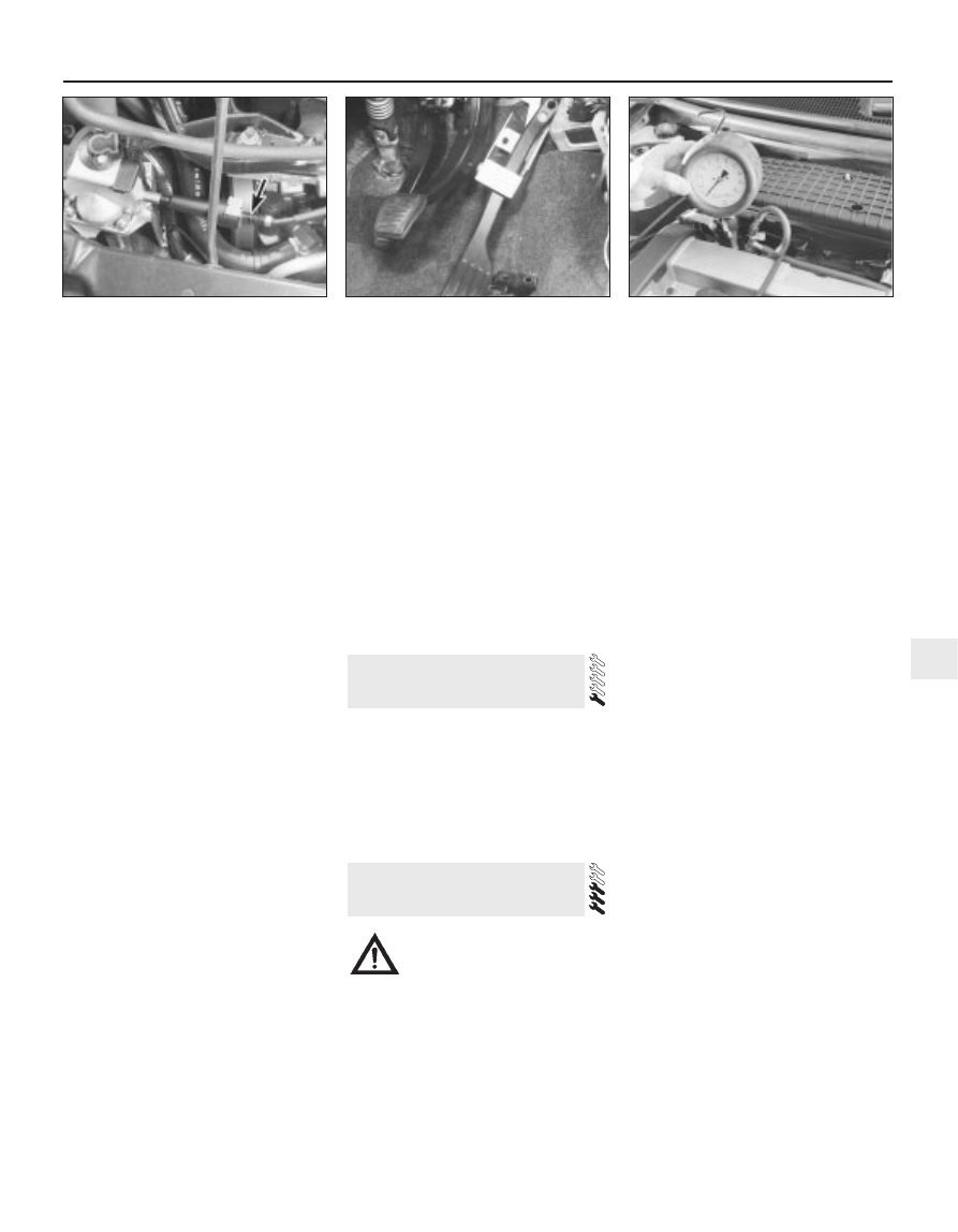
6.11 Location of TCS throttle actuator-to-
throttle housing cable adjuster (arrowed)
7.2 Removing the accelerator pedal
assembly
8.4 A fuel pressure gauge, equipped with
an adaptor to suit the Schrader-type valve
on the fuel rail pressure test/release fitting,
is needed to check fuel pressure