Ford Mondeo (petrol engines). Manual - part 24
 

  Index      Ford     Ford Mondeo - service and repair manual (petrol engines)


Search            


Content   ..  22  23  24  25   ..


Ford Mondeo (petrol engines). Manual - part 24


Heater blower motor

Removal

Disconnect the battery negative (earth) lead
(see Chapter 5, Section 1).
Release the four clips (by pulling them out)
securing the passenger side footwell upper
trim panel, then withdraw the panel.
Unplug the motor’s electrical connector.
Lift the motor’s retaining lug slightly, twist
the motor anti-clockwise (seen from beneath)
through approximately 30°, then withdraw the
assembly.
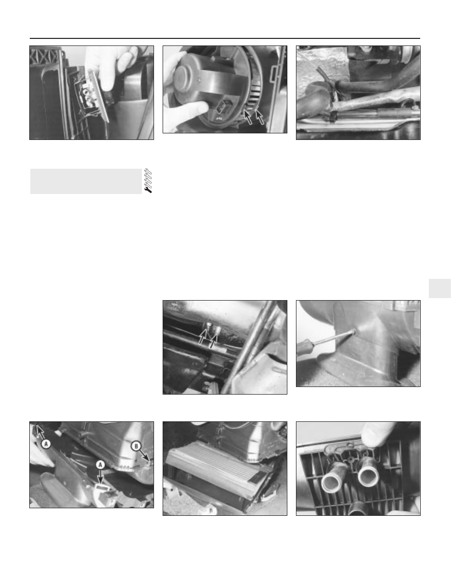
The motor’s control resistor can be
removed by sliding a slim screwdriver into the
slot provided in one end. Press the
screwdriver in approximately 5 mm against
spring pressure, and prise the resistor out
(see illustration).

Refitting

Refitting is the reverse of the removal
procedure. Refit the motor, and twist it
clockwise until the retaining lug engages
securely (see illustration).

Heater matrix

Removal

Disconnect the battery negative (earth) lead
(see Chapter 5, Section 1).

Drain the cooling system (see Chapter 1).
Disconnect the coolant hoses from the
heater matrix unions protruding through the
engine compartment bulkhead (see
illustrations)
.
10 Working inside the passenger
compartment, remove the trim panels from
each footwell, just in front of the centre
console. Each panel is secured by two
screws. If additional clearance is required, the
centre console can be removed as well (see
Chapter 11), but this is not essential.
11 Remove the single screw to release the air
duct in the base of the heater unit (see
illustration)
.
12 Remove the three Torx-type screws (size
T20) securing the air distributor to the heater
unit bottom cover, then release the clips.

There is a single plastic clip on each side, and
additional metal clips may be found. Push the
duct up to retract it, and withdraw the air
distributor (see illustration).
13 Release the clips - there are two plastic
clips on each side, and additional metal clips
may be found - then withdraw the heater
unit’s bottom cover, complete with the matrix
(see illustration).
14 Undo the screw and withdraw the clamp
to separate the matrix from the bottom cover
(see illustration).

Refitting

15 Refitting is the reverse of the removal
procedure. Additional metal clips may be
required to secure the heater unit’s bottom
cover and the air distributor. Ensure that the

9 Heater/ventilation components

- removal and refitting

Cooling, heating and air conditioning systems  3•7

3

9.12  . . . release clips (A) to free air

distributor from base of heater unit - note

clips (B) securing . . .

9.13  . . . heater unit’s bottom cover,

complete with matrix

9.14  Remove clamp (one screw) to separate

matrix from heater unit’s bottom cover

9.5  Heater blower motor control resistor

can be prised out of heater unit

9.6  Ensure blower motor retaining lug

(arrowed) engages securely in heater unit

on reassembly

9.9A  Coolant pipes to heater matrix must

be disconnected . . .

9.9B  . . . but can be reached best from

beneath vehicle (arrowed)

9.11  Remove screw to allow air duct to be

retracted into air distributor at base of

heater unit . . .

duct is lowered from the air distributor and
secured with its screw.
16 Refill the cooling system with the proper
mixture of antifreeze and water (see Chapter
1). Start the engine and allow it to reach
normal operating temperature, indicated by
the radiator top hose becoming hot. Recheck
the coolant level and add more if required,
then check for leaks. Check the operation of
the heater.

Pollen filter

17 Refer to Chapter 1.

Blower/air conditioning control

Removal

Disconnect the battery negative (earth) lead
(see Chapter 5, Section 1).
Remove the ashtray. Referring to the
relevant Sections of Chapter 11, undo the two
upper screws from the centre console and
pull out the cassette storage compartment,
then remove the radio/cassette player.
Pull the heater control/radio bezel out of the
three clips securing its top edge, pull it
forwards and unplug the switch electrical
connector (where fitted).
Pull off the heater control knobs, and
remove the screw securing each end of the
heater control unit (see illustration). Pull the
control unit out of the facia.
Unplug the two electrical connectors from
the blower/air conditioning control. Remove
the retaining screw and withdraw the control,
twisting it to release it from the panel.

Refitting

Refitting is the reverse of the removal
procedure. Check the operation of the control
on completion.

Temperature control

Removal

Remove the heater control unit as
described in paragraphs 1 to 4 above.
On vehicles without air conditioning,

unhook the operating cable from the
temperature control (see illustration); where
air conditioning is fitted, unplug the control’s
electrical connector. Undo the retaining
screw, and withdraw the control.

Refitting

Refitting is the reverse of the removal
procedure; check the operation of the control
on completion.

Air distribution control

Removal

10 Remove the heater control unit as
described in paragraphs 1 to 4 above. Unplug
the electrical connectors, and unhook the
operating cable (where fitted) to withdraw the
unit (see illustration).
11 Use a pair of slim screwdrivers to release
the clips on each side of the control, then
withdraw the control from the unit.

Refitting

12 Refitting is the reverse of the removal

procedure. Check the operation of the
controls on completion.

General information

The air conditioning system consists of a

condenser mounted in front of the radiator, an
evaporator mounted adjacent to the heater
matrix, a compressor mounted on the engine,
an accumulator/dehydrator, and the plumbing
connecting all of the above components - this
contains a choke (or “venturi”) mounted in the
inlet to the evaporator, which creates the drop
in pressure required to produce the cooling
effect (see illustration).

A blower fan forces the warmer air of the

passenger compartment through the
evaporator core (rather like a radiator in
reverse), transferring the heat from the air to

11 Air conditioning system 

general information and
precautions

10 Heater/air conditioning

controls - removal and refitting

3•8 Cooling, heating and air conditioning systems

10.4  Remove screws (arrowed) securing

each end of heater control unit

10.8  Unhooking operating cable from

temperature control - note retaining screw

(arrowed)

10.10  Unplugging electrical connectors

from rear of heater control unit

11.1  Air conditioning system components

1  Quick-release Schrader valve-type 

coupling - high-pressure side

2  Quick-release Schrader valve-type 

coupling - low-pressure side

3  Pressure-cycling switch - low-pressure side

4  Accumulator/dehydrator
5  Compressor
6  Condenser
7  Pressure-regulating switch - high-pressure

side

the refrigerant. The liquid refrigerant boils off
into low-pressure vapour, taking the heat with
it when it leaves the evaporator.

Precautions

Warning: The air conditioning
system is under high pressure.
Do not loosen any fittings or
remove any components until

after the system has been discharged. Air
conditioning refrigerant should be properly
discharged into an approved type of
container, at a dealer service department
or an automotive air conditioning repair
facility capable of handling R134a
refrigerant. Always wear eye protection
when disconnecting air conditioning
system fittings.

When an air conditioning system is fitted, it

is necessary to observe the following special
precautions whenever dealing with any part of
the system, its associated components, and
any items which necessitate disconnection of
the system:
(a) While the refrigerant used - R134a - is

less damaging to the environment than
the previously-used R12, it is still a very
dangerous substance. It must not be
allowed into contact with the skin or eyes,
or there is a risk of frostbite. It must also
not be discharged in an enclosed space -
while it is not toxic, there is a risk of
suffocation. The refrigerant is heavier than
air, and so must never be discharged over
a pit.

(b) The refrigerant must not be allowed to

come in contact with a naked flame,
otherwise a poisonous gas will be created
- under certain circumstances, this can
form an explosive mixture with air. For
similar reasons, smoking in the presence
of refrigerant is highly dangerous,
particularly if the vapour is inhaled
through a lighted cigarette.

(c) Never discharge the system to the

atmosphere - R134a is not an ozone-
depleting ChloroFluoroCarbon (CFC) as is
R12, but is instead a hydrofluorocarbon,
which causes environmental damage by
contributing to the “greenhouse effect” if
released into the atmosphere.

(d) R134a refrigerant must not be mixed with

R12; the system uses different seals (now
green-coloured, previously black) and has
different fittings requiring different tools,
so that there is no chance of the two
types of refrigerant becoming mixed
accidentally.

(e) If for any reason the system must be

disconnected, entrust this task to your
Ford dealer or a refrigeration engineer.

(f)

It is essential that the system be
professionally discharged prior to using
any form of heat - welding, soldering,
brazing, etc - in the vicinity of the system,
before having the vehicle oven-dried at a
temperature exceeding 70°C after
repainting, and before disconnecting any
part of the system.

Warning: The air conditioning
system is under high pressure.
Do not loosen any fittings or

remove any components until after the
system has been discharged. Air
conditioning refrigerant should be properly
discharged into an approved type of
container, at a dealer service department
or an automotive air conditioning repair
facility capable of handling R134a
refrigerant. Cap or plug the pipe lines as
soon as they are disconnected, to prevent
the entry of moisture. Always wear eye
protection when disconnecting air
conditioning system fittings.
Note: This Section refers to the components
of the air conditioning system itself - refer to
Sections 9 and 10 for details of components
common to the heating/ventilation system.

Condenser

Have the refrigerant discharged at a dealer
service department or an automotive air
conditioning repair facility.
Disconnect the battery negative (earth) lead
(see Chapter 5, Section 1).
Remove the radiator undershield (see
Chapter 1).
Using the Ford service tool 34-001,
disconnect the refrigerant lines from the
condenser. Immediately cap the open fittings,
to prevent the entry of dirt and moisture.
Unbolt the condenser (see illustration 7.5)
and lift it out of the vehicle. Store it upright, to
prevent oil loss.
Refitting is the reverse of removal.
If a new condenser was installed, add 20 cc
of refrigerant oil to the system.
Have the system evacuated, charged and
leak-tested by the specialist who discharged
it.

Evaporator

The evaporator is mounted with the heater
matrix. Apart from the need to have the
refrigerant discharged, and to use Ford
service tools 34-001 and 34-003 to
disconnect the lines, the procedure is as
described in Section 9 of this Chapter.
10 On reassembly, if a new evaporator was
installed, add 20 cc of refrigerant oil to the
system.
11 Have the system evacuated, charged and
leak-tested by the specialist who discharged
it.

Compressor

12 Have the refrigerant discharged at a
dealer service department or an automotive
air conditioning repair facility.
13 Disconnect the battery negative (earth)
lead (see Chapter 5, Section 1).
14 Remove the radiator undershield (see
Chapter 1).

15 Remove the auxiliary drivebelt (see
Chapter 1).
16 Unbolt the compressor from the cylinder
block/crankcase, press it to one side, and
unscrew the clamping bolt to disconnect the
refrigerant lines. Plug the line connections,
swing the compressor upright, unplug its
electrical connector, then withdraw the
compressor from the vehicle. Note: Keep the
compressor level during handling and storage.
If the compressor has seized, or if you find
metal particles in the refrigerant lines, the
system must be flushed out by an air
conditioning technician, and the
accumulator/dehydrator must be renewed.
17 Prior to installation, turn the compressor
clutch centre six times, to disperse any oil that
has collected in the head.
18 Refit the compressor in the reverse order
of removal; renew all seals disturbed.
19 If you are installing a new compressor,
refer to the compressor manufacturer’s
manuals for adding refrigerant oil to the
system.
20 Have the system evacuated, charged and
leak-tested by the specialist that discharged
it.

Accumulator/dehydrator

21 Have the refrigerant discharged at a
dealer service department or an automotive
air conditioning repair facility.
22 Disconnect the battery negative (earth)
lead (see Chapter 5, Section 1).
23 The accumulator/dehydrator, which acts
as a reservoir and filter for the refrigerant, is
located in the left-hand front corner of the
engine compartment. Using the Ford service
tool 34-003, disconnect the refrigerant line
next to the accumulator/dehydrator from the
compressor. Immediately cap the open
fittings, to prevent the entry of dirt and
moisture, then unplug the pressure-cycling
switch electrical connector (see illustration).
24 Remove the radiator undershield (see
Chapter 1).
25 Unbolt the accumulator/dehydrator from
the front suspension subframe.
26 Using the Ford service tool 34-003,
disconnect the lower refrigerant line from the
accumulator/dehydrator. It may be necessary

12 Air conditioning system

components 
removal and refitting

Cooling, heating and air conditioning systems  3•9

3

12.23  Unplug pressure-cycling switch

electrical connector (arrowed)

to unscrew the pressure-cycling switch to
allow the use of the tool. Immediately cap the
open fittings, to prevent the entry of dirt and
moisture.
27 Withdraw the accumulator/dehydrator.
28 Refit the accumulator/dehydrator in the
reverse order of removal; renew all seals
disturbed.
29 If you are installing a new accumulator/
dehydrator, refer to the manufacturer’s
manuals for adding refrigerant oil to the
system.
30 Have the system evacuated, charged and
leak-tested by the specialist that discharged
it.

Pressure-cycling and pressure-
regulating switches

31 Have the refrigerant discharged at a
dealer service department or an automotive
air conditioning repair facility.
32 Disconnect the battery negative (earth)
lead (see Chapter 5, Section 1).
33 Unplug the switch electrical connector,
and unscrew it (see illustration).
34 Refitting is the reverse of the removal
procedure; there is no need to top-up the
refrigerant oil.
35 Have the system evacuated, charged and
leak-tested by the specialist that discharged
it.

3•10 Cooling, heating and air conditioning systems

12.33  Unplug pressure-regulating switch

electrical connector (arrowed)


Content   ..  22  23  24  25   ..