Ford Mondeo (petrol engines). Manual - part 17
 

  Index      Ford     Ford Mondeo - service and repair manual (petrol engines)


Search            


Content   ..  15  16  17  18   ..


Ford Mondeo (petrol engines). Manual - part 17


Chapter 2  Part B: Engine removal 
and general engine overhaul procedures

Compression test - description and interpretation  . . . See Chapter 2A
Crankshaft - inspection  . . . . . . . . . . . . . . . . . . . . . . . . . . . . . . . . . . . 13
Crankshaft - refitting and main bearing running 

clearance check  . . . . . . . . . . . . . . . . . . . . . . . . . . . . . . . . . . . . . . 17

Crankshaft - removal . . . . . . . . . . . . . . . . . . . . . . . . . . . . . . . . . . . . . 10
Cylinder block/crankcase - cleaning and inspection  . . . . . . . . . . . . 11
Cylinder head - dismantling  . . . . . . . . . . . . . . . . . . . . . . . . . . . . . . .

6

Cylinder head - reassembly  . . . . . . . . . . . . . . . . . . . . . . . . . . . . . . .

8

Cylinder head and valve components - cleaning and inspection  . . .

7

Engine - initial start-up after overhaul  . . . . . . . . . . . . . . . . . . . . . . . . 19
Engine overhaul - dismantling sequence  . . . . . . . . . . . . . . . . . . . . .

5

Engine overhaul - general information  . . . . . . . . . . . . . . . . . . . . . . .

2

Engine overhaul - reassembly sequence  . . . . . . . . . . . . . . . . . . . . . 15
Engine/transmission - removal and refitting  . . . . . . . . . . . . . . . . . . .

4

Engine/transmission removal - methods and precautions  . . . . . . . .

3

General information . . . . . . . . . . . . . . . . . . . . . . . . . . . . . . . . . . . . . .

1

Main and big-end bearings - inspection  . . . . . . . . . . . . . . . . . . . . . . 14
Piston/connecting rod assemblies - inspection  . . . . . . . . . . . . . . . . 12
Piston/connecting rod assemblies - refitting and 

big-end bearing running clearance check . . . . . . . . . . . . . . . . . . . 18

Piston/connecting rod assemblies - removal  . . . . . . . . . . . . . . . . . .

9

Piston rings - refitting  . . . . . . . . . . . . . . . . . . . . . . . . . . . . . . . . . . . . 16

Cylinder head

Maximum permissible gasket surface  distortion  . . . . . . . . . . . . . . . . . .

0.10 mm

Valve seat included angle  . . . . . . . . . . . . . . . . . . . . . . . . . . . . . . . . . . . .

90°

Valve guide bore  . . . . . . . . . . . . . . . . . . . . . . . . . . . . . . . . . . . . . . . . . . .

6.060 to 6.091 mm

Valves - general

Inlet

Exhaust

Valve lift  . . . . . . . . . . . . . . . . . . . . . . . . . . . . . . . . . . . . . . . . . . . . . . . . . .

7.500 to 7.685 mm

7.610 to 7.765 mm

Valve length . . . . . . . . . . . . . . . . . . . . . . . . . . . . . . . . . . . . . . . . . . . . . . .

96.870 to 97.330 mm

96.470 to  96.930 mm

Valve head diameter:

1.6 litre engine  . . . . . . . . . . . . . . . . . . . . . . . . . . . . . . . . . . . . . . . . . . .

26.0 mm

24.5 mm

1.8 and 2.0 litre engines  . . . . . . . . . . . . . . . . . . . . . . . . . . . . . . . . . . .

32.0 mm

28.0 mm

Valve stem diameter  . . . . . . . . . . . . . . . . . . . . . . . . . . . . . . . . . . . . . . . .

6.028 to 6.043 mm

6.010 to6.025 mm

Valve stem-to-guide clearance  . . . . . . . . . . . . . . . . . . . . . . . . . . . . . . . .

0.017 to 0.064 mm

0.035 to 0.081 mm

Cylinder block

Cylinder bore diameter - 1.6 litre engine:

Class 1 . . . . . . . . . . . . . . . . . . . . . . . . . . . . . . . . . . . . . . . . . . . . . . . . .

76.000 to 76.010 mm

Class 2 . . . . . . . . . . . . . . . . . . . . . . . . . . . . . . . . . . . . . . . . . . . . . . . . .

76.010 to 76.020 mm

Class 3 . . . . . . . . . . . . . . . . . . . . . . . . . . . . . . . . . . . . . . . . . . . . . . . . .

76.020 to 76.030 mm

Cylinder bore diameter - 1.8 litre engine:

Class 1 . . . . . . . . . . . . . . . . . . . . . . . . . . . . . . . . . . . . . . . . . . . . . . . . .

80.600 to 80.610 mm

Class 2 . . . . . . . . . . . . . . . . . . . . . . . . . . . . . . . . . . . . . . . . . . . . . . . . .

80.610 to 80.620 mm

Class 3 . . . . . . . . . . . . . . . . . . . . . . . . . . . . . . . . . . . . . . . . . . . . . . . . .

80.620 to 80.630 mm

Cylinder bore diameter - 2.0 litre engine:

Class 1 . . . . . . . . . . . . . . . . . . . . . . . . . . . . . . . . . . . . . . . . . . . . . . . . .

84.800 to 84.810 mm

Class 2 . . . . . . . . . . . . . . . . . . . . . . . . . . . . . . . . . . . . . . . . . . . . . . . . .

84.810 to 84.820 mm

Class 3 . . . . . . . . . . . . . . . . . . . . . . . . . . . . . . . . . . . . . . . . . . . . . . . . .

84.820 to 84.830 mm

2B•1

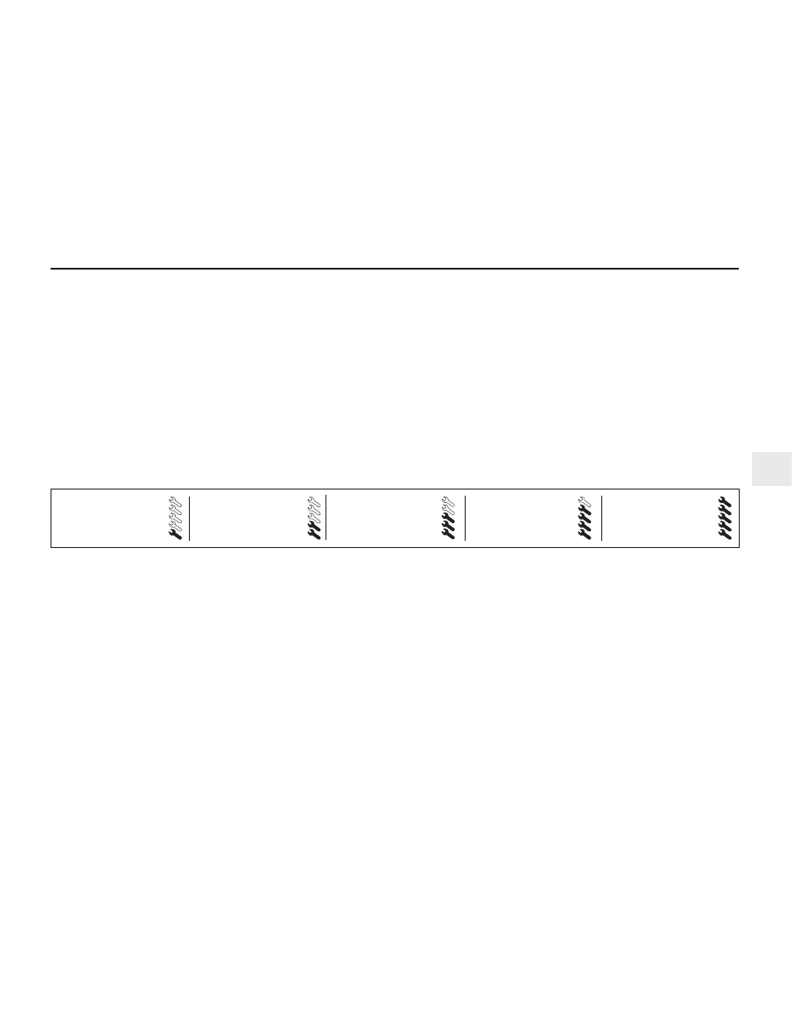
Easy, suitable for
novice with little
experience

Fairly easy, suitable
for beginner with
some experience

Fairly difficult, suitable
for competent DIY
mechanic

Difficult, suitable for
experienced  DIY
mechanic

Very difficult,
suitable for expert DIY
or  professional

Degrees of difficulty

Specifications

Contents

2B

Pistons and piston rings

Piston diameter - 1.6 litre engine:

Class 1 . . . . . . . . . . . . . . . . . . . . . . . . . . . . . . . . . . . . . . . . . . . . . . . . .

75.975 to 75.985 mm

Class 2 . . . . . . . . . . . . . . . . . . . . . . . . . . . . . . . . . . . . . . . . . . . . . . . . .

75.985 to 75.995 mm

Class 3 . . . . . . . . . . . . . . . . . . . . . . . . . . . . . . . . . . . . . . . . . . . . . . . . .

75.995 to 76.005 mm

Piston diameter - 1.8 litre engine:

Class 1 . . . . . . . . . . . . . . . . . . . . . . . . . . . . . . . . . . . . . . . . . . . . . . . . .

80.570 to 80.580 mm

Class 2 . . . . . . . . . . . . . . . . . . . . . . . . . . . . . . . . . . . . . . . . . . . . . . . . .

80.580 to 80.590 mm

Class 3 . . . . . . . . . . . . . . . . . . . . . . . . . . . . . . . . . . . . . . . . . . . . . . . . .

80.590 to 80.600 mm

Piston diameter - 2.0 litre engine:

Class 1 . . . . . . . . . . . . . . . . . . . . . . . . . . . . . . . . . . . . . . . . . . . . . . . . .

84.770 to 84.780 mm

Class 2 . . . . . . . . . . . . . . . . . . . . . . . . . . . . . . . . . . . . . . . . . . . . . . . . .

84.780 to 84.790 mm

Class 3 . . . . . . . . . . . . . . . . . . . . . . . . . . . . . . . . . . . . . . . . . . . . . . . . .

84.790 to 84.800 mm

Oversizes - all engines  . . . . . . . . . . . . . . . . . . . . . . . . . . . . . . . . . . . . . .

None available

Piston-to-cylinder bore clearance . . . . . . . . . . . . . . . . . . . . . . . . . . . . . .

No information available at time  of writing

Piston ring end gaps - installed:

Top compression ring - 1.6 and  1.8 litre engines . . . . . . . . . . . . . . . .

0.30 to 0.50 mm

Top compression ring - 2.0 litre  engine  . . . . . . . . . . . . . . . . . . . . . . .

0.26 to 0.50 mm

Second compression ring  . . . . . . . . . . . . . . . . . . . . . . . . . . . . . . . . . .

0.30 to 0.50 mm

Oil control ring - 1.6 litre engine  . . . . . . . . . . . . . . . . . . . . . . . . . . . . .

0.25 to 1.00 mm

Oil control ring - 1.8 litre engine  . . . . . . . . . . . . . . . . . . . . . . . . . . . . .

0.38 to 1.14 mm

Oil control ring - 2.0 litre engine  . . . . . . . . . . . . . . . . . . . . . . . . . . . . .

0.40 to 1.40 mm

Gudgeon pin

Diameter:

White colour code/piston crown marked “A”  . . . . . . . . . . . . . . . . . . .

20.622 to 20.625 mm

Red colour code/piston crown  marked “B”  . . . . . . . . . . . . . . . . . . . .

20.625 to 20.628 mm

Blue colour code/piston crown marked “C”  . . . . . . . . . . . . . . . . . . . .

20.628 to 20.631 mm

Clearance in piston  . . . . . . . . . . . . . . . . . . . . . . . . . . . . . . . . . . . . . . . . .

0.010 to 0.016 mm

Connecting rod small-end eye  internal diameter  . . . . . . . . . . . . . . . . . .

20.589 to 20.609 mm

Interference fit in connecting rod  . . . . . . . . . . . . . . . . . . . . . . . . . . . . . .

0.011 to 0.042 mm

Crankshaft and bearings

Main bearing shell standard inside  diameter - installed  . . . . . . . . . . . .

58.011 to 58.038 mm

Main bearing journal standard  diameter  . . . . . . . . . . . . . . . . . . . . . . . .

57.980 to 58.000 mm

Main bearing journal-to-shell  running clearance  . . . . . . . . . . . . . . . . . .

0.011 to 0.058 mm

Main bearing shell undersizes  available . . . . . . . . . . . . . . . . . . . . . . . . .

0.02 mm, 0.25 mm

Big-end bearing shell standard inside diameter - installed . . . . . . . . . . .

46.926 to 46.960 mm

Crankpin (big-end) bearing journal  standard diameter  . . . . . . . . . . . . .

46.890 to 46.910 mm

Crankpin (big-end) bearing journal-to-shell running clearance . . . . . . . .

0.016 to 0.070 mm

Big-end bearing shell undersizes  available  . . . . . . . . . . . . . . . . . . . . . .

0.02 mm, 0.25 mm

Crankshaft endfloat . . . . . . . . . . . . . . . . . . . . . . . . . . . . . . . . . . . . . . . . .

0.090 to 0.310 mm

Torque wrench settings

Nm

lbf ft

Main bearing cap bolts and nuts  . . . . . . . . . . . . . . . . . . . . . . . . . . . . . .

80

59

Big-end bearing cap bolts:

Stage 1  . . . . . . . . . . . . . . . . . . . . . . . . . . . . . . . . . . . . . . . . . . . . . . . .

18

13

Stage 2  . . . . . . . . . . . . . . . . . . . . . . . . . . . . . . . . . . . . . . . . . . . . . . . .

Angle-tighten a further 90°

Piston-cooling oil jet/blanking  plug Torx screws  . . . . . . . . . . . . . . . . . .

10

7

Cylinder block and head oilway  blanking plugs:

M6 x 10  . . . . . . . . . . . . . . . . . . . . . . . . . . . . . . . . . . . . . . . . . . . . . . . .

8 to 11

6 to 8

M10 x 11.5 - in block . . . . . . . . . . . . . . . . . . . . . . . . . . . . . . . . . . . . . .

24

17

1/4 PTF plug - in block  . . . . . . . . . . . . . . . . . . . . . . . . . . . . . . . . . . . .

25

18

Power steering pump/air conditioning  compressor mounting 
bracket-to-cylinder block bolts  . . . . . . . . . . . . . . . . . . . . . . . . . . . . . . . .

47

35

Exhaust manifold heat shield  mounting bracket-to-cylinder 
block bolts . . . . . . . . . . . . . . . . . . . . . . . . . . . . . . . . . . . . . . . . . . . . . . . .

32

24

Crankcase breather system:

Oil separator-to-cylinder block  bolts  . . . . . . . . . . . . . . . . . . . . . . . . .

10

7

Pipe-to-cylinder head bolt . . . . . . . . . . . . . . . . . . . . . . . . . . . . . . . . . .

23

17

Water pump bolts  . . . . . . . . . . . . . . . . . . . . . . . . . . . . . . . . . . . . . . . . . .

See Chapter 3

Driveshaft support bearing bracket-to-cylinder block bolts  . . . . . . . . . .

48

35

Transmission-to-engine bolts  . . . . . . . . . . . . . . . . . . . . . . . . . . . . . . . . .

See Part A of this Chapter

Engine/transmission mounting  fasteners . . . . . . . . . . . . . . . . . . . . . . . .

See Part A of this Chapter

Front suspension subframe bolts  . . . . . . . . . . . . . . . . . . . . . . . . . . . . . .

130

96

Note: Refer to Part A of this Chapter for remaining torque wrench settings.

2B•2 Engine removal and general engine overhaul procedures

How to use this Chapter

This Part of Chapter 2 is devoted to

engine/transmission removal and refitting, to
those repair procedures requiring the removal
of the engine/transmission from the vehicle,
and to the overhaul of engine components. It
includes only the Specifications relevant to
those procedures. Refer to Part A for
additional Specifications, if required.

General information

The information ranges from advice

concerning preparation for an overhaul and
the purchase of replacement parts, to detailed
step-by-step procedures covering removal
and installation of internal engine components
and the inspection of parts.

The following Sections have been written

based on the assumption that the engine has
been removed from the vehicle. For
information concerning in-vehicle engine
repair, as well as removal and installation of
the external components necessary for the
overhaul, see Part A of this Chapter and
Section 5 of this Part.

When overhauling this engine, it is essential

to establish first exactly what replacement
parts are available. At the time of writing,
components such as the piston rings are not
available separately from the
piston/connecting rod assemblies; pistons,
gudgeon pins and valve guides are not
available separately, and very few under- or
oversized components are available for
engine reconditioning. In most cases, it would
appear that the easiest and most
economically-sensible course of action is to
replace a worn or damaged engine with an
exchange unit.

It’s not always easy to determine when, or

if, an engine should be completely
overhauled, as a number of factors must be
considered.

High mileage is not necessarily an

indication that an overhaul is needed, while
low mileage doesn’t preclude the need for an
overhaul. Frequency of servicing is probably
the most important consideration. An engine
that’s had regular and frequent oil and filter
changes, as well as other required
maintenance, will most likely give many
thousands of miles of reliable service.
Conversely, a neglected engine may require
an overhaul very early in its life.

Excessive oil consumption is an indication

that piston rings, valve seals and/or valve
guides are in need of attention. Make sure

that oil leaks aren’t responsible before
deciding that the rings and/or guides are
worn. Perform a cylinder compression check
(Part A of this Chapter, Section 3) to
determine the extent of the work required.

Loss of power, rough running, knocking or

metallic engine noises, excessive valve train
noise and high fuel consumption rates may
also point to the need for an overhaul,
especially if they’re all present at the same
time. If a full service doesn’t remedy the
situation, major mechanical work is the only
solution.

An engine overhaul involves restoring all

internal parts to the specification of a new
engine.  Note: Always check first what
replacement parts are available before
planning any overhaul operation; refer to
Section 1 of this Part. Ford dealers, or a good
engine reconditioning specialist/automotive
parts supplier may be able to suggest
alternatives which will enable you to overcome
the lack of replacement parts.

During an overhaul, it is usual to renew the

piston rings, and to rebore and/or hone the
cylinder bores; where the rebore is done by an
automotive machine shop, new oversize
pistons and rings will also be installed - all
these operations, of course, assume the
availability of suitable replacement parts. The
main and big-end bearings are generally
renewed and, if necessary, the crankshaft
may be reground to restore the journals.
Generally, the valves are serviced as well,
since they’re usually in less-than-perfect
condition at this point. While the engine is
being overhauled, other components, such as
the starter and alternator, can be renewed as
well, or rebuilt, if the necessary parts can be
found. The end result should be an as-new
engine that will give many trouble-free miles.
Note: Critical cooling system components
such as the hoses, drivebelt, thermostat and
water pump MUST be replaced with new
parts when an engine is overhauled. The
radiator should be checked carefully, to
ensure that it isn’t clogged or leaking (see
Chapter 3). Also, as a general rule, the oil
pump should be renewed when an engine is
rebuilt.

Before beginning the engine overhaul, read

through the entire procedure to familiarise
yourself with the scope and requirements of
the job. Overhauling an engine isn’t difficult,
but it is time-consuming. Plan on the vehicle
being off the road for a minimum of two
weeks, especially if parts must be taken to an
automotive machine shop for repair or
reconditioning. Check on availability of parts,
and make sure that any necessary special
tools and equipment are obtained in advance.
Most work can be done with typical hand
tools, although a number of precision
measuring tools are required, for inspecting
parts to determine if they must be replaced.
Often, an automotive machine shop will
handle the inspection of parts, and will offer
advice concerning reconditioning and

replacement. 

Note: Always wait until the

engine has been completely dismantled, and
all components, especially the cylinder
block/crankcase, have been inspected, before
deciding what service and repair operations
must be performed by an automotive machine
shop. Since the block’s condition will be the
major factor to consider when determining
whether to overhaul the original engine or buy
a rebuilt one, never purchase parts or have
machine work done on other components
until the cylinder block/crankcase has been
thoroughly inspected. 
As a general rule, time
is the primary cost of an overhaul, so it
doesn’t pay to install worn or sub-standard
parts.

As a final note, to ensure maximum life and

minimum trouble from a rebuilt engine,
everything must be assembled with care, in a
spotlessly-clean environment.

If you’ve decided that an engine must be

removed for overhaul or major repair work,
several preliminary steps should be taken.

Locating a suitable place to work is

extremely important. Adequate work space,
along with storage space for the vehicle, will
be needed. If a workshop or garage isn’t
available, at the very least, a flat, level, clean
work surface made of concrete or asphalt is
required.

Cleaning the engine compartment and

engine/transmission before beginning the
removal procedure will help keep tools clean
and organized.

The engine can only be withdrawn by

removing it complete with the transmission;
the vehicle’s body must be raised and
supported securely, sufficiently high that the
engine/transmission can be unbolted as a
single unit and lowered to the ground; the
engine/transmission unit can then be
withdrawn from under the vehicle and
separated. An engine hoist or A-frame will
therefore be necessary. Make sure the
equipment is rated in excess of the combined
weight of the engine and transmission. Safety
is of primary importance, considering the
potential hazards involved in removing the
engine/transmission from the vehicle.

If this is the first time you have removed an

engine, a helper should ideally be available.
Advice and aid from someone more
experienced would also be helpful. There are
many instances when one person cannot
simultaneously perform all of the operations
required when removing the engine/
transmission from the vehicle.

Plan the operation ahead of time. Arrange for,

or obtain, all of the tools and equipment you’ll
need prior to beginning the job. Some of the
equipment necessary to perform
engine/transmission removal and installation

3 Engine/transmission removal -

methods and precautions

2 Engine overhaul 

general information

1 General information

Engine removal and general engine overhaul procedures  2B•3

2B

safely and with relative ease, and which may
have to be hired or borrowed, includes (in
addition to the engine hoist) a heavy-duty trolley
jack, a strong pair of axle stands, some wooden
blocks, and an engine dolly (a low, wheeled
platform capable of taking the weight of the
engine/transmission, so that it can be moved
easily when on the ground). A complete set of
spanners and sockets (as described in the front
of this manual) will obviously be needed,
together with plenty of rags and cleaning
solvent for mopping-up spilled oil, coolant and
fuel. If the hoist is to be hired, make sure that
you arrange for it in advance, and perform all of
the operations possible without it beforehand.
This will save you money and time.

Plan for the vehicle to be out of use for

quite a while. A machine shop will be required
to perform some of the work which the do-it-
yourselfer can’t accomplish without special
equipment. These establishments often have
a busy schedule, so it would be a good idea
to consult them before removing the engine,
to accurately estimate the amount of time
required to rebuild or repair components that
may need work.

Always be extremely careful when removing

and installing the engine/transmission.
Serious injury can result from careless
actions. By planning ahead and taking your
time, the job (although a major task) can be
accomplished successfully.

Warning: Petrol is extremely
flammable, so take extra
precautions when disconnecting
any part of the fuel system. Don’t

smoke, or allow naked flames or bare light
bulbs in or near the work area, and don’t
work in a garage where a natural gas
appliance (such as a clothes dryer or water
heater) is installed. If you spill petrol on
your skin, rinse it off immediately. Have a
fire extinguisher rated for petrol fires
handy, and know how to use it.

Note: Read through the entire Section, as well
as reading the advice in the preceding Section,
before beginning this procedure. The engine
and transmission are removed as a unit,
lowered to the ground and removed from
underneath, then separated outside the vehicle.

Removal

Park the vehicle on firm, level ground, apply
the handbrake firmly, and slacken the nuts
securing both front roadwheels.
Relieve the fuel system pressure (see
Chapter 4).
Disconnect the battery negative (earth) lead
- see Chapter 5, Section 1. For better access
the battery may be removed completely (see
Chapter 5).
Place protective covers on the wings and
engine compartment front crossmember, then
remove the bonnet (see Chapter 11).
Whenever you disconnect any vacuum
lines, coolant and emissions hoses, wiring
loom connectors, earth straps and fuel lines
as part of the following procedure, always
label them clearly, so that they can be
correctly reassembled.
Unplug the two electrical connectors,

disconnect the vacuum hose (where fitted)
and disconnect the crankcase breather hose
from the cylinder head cover, then remove the
complete air cleaner assembly, with the air
mass meter, the resonator and the plenum
chamber (see Chapter 4).
Equalise the pressure in the fuel tank by
removing the filler cap, then undo the fuel
feed and return lines connecting the engine to
the chassis (see Chapter 4). Plug or cap all
open fittings (see illustration).
Disconnect the accelerator cable from the
throttle linkage as described in Chapter 4 -
where fitted, also disconnect the cruise
control actuator cable (see Chapter 12).
Secure the cable(s) clear of the
engine/transmission.
Releasing its wire clip, unplug the power
steering pressure switch electrical connector,
then unbolt the power steering high-pressure
pipe and the earth lead from the cylinder head
rear support plate/engine lifting eye (see
illustrations)
.
10 Marking or labelling all components as
they are disconnected (see paragraph 5
above), disconnect the vacuum hoses as
follows:

4 Engine/transmission 

removal and refitting

2B•4 Engine removal and general engine overhaul procedures

4.7  Note colour-coding of unions when

disconnecting fuel feed and return lines

4.9A  Unplug the power steering pressure

switch electrical connector . . .

4.9B  . . . unbolt the power steering high-

pressure pipe . . .

Whenever any wiring is disconnected,

. . . vacuum hoses and pipes should 

mark or label it as shown, to ensure

be similarly marked

correct reconnection . . .

Masking tape and/or a touch-up paint applicator work well for marking items. Take
instant photos, or sketch the locations of components and brackets.


Content   ..  15  16  17  18   ..