Ford Mondeo (petrol engines). Manual - part 7
 

  Index      Ford     Ford Mondeo - service and repair manual (petrol engines)


Search            


Content   ..  5  6  7  8   ..


Ford Mondeo (petrol engines). Manual - part 7


amperage charger, but don’t use one rated
more than 1/10th the amp/hour rating of the
battery (ie no more than 5 amps, typically).
Rapid boost charges that claim to restore the
power of the battery in one to two hours are
hardest on the battery, and can damage
batteries not in good condition. This type of
charging should only be used in emergency
situations.
14 The average time necessary to charge a
battery should be listed in the manuals that
come with the charger. As a general rule, a
trickle charger will charge a battery in 12 to 
16 hours.

Check the seat belts for satisfactory
operation and condition. Inspect the webbing
for fraying and cuts. Check that they retract
smoothly and without binding into their reels.
Check that the seat belt mounting bolts are
tight, and if necessary tighten them to the
specified torque wrench setting.

General

The auxiliary drivebelt is of the flat, multi-
ribbed (or “polyvee”) type, and is located on
the right-hand end of the engine. It drives the
alternator, water pump, power steering pump
and (when fitted) the air conditioning
compressor from the engine’s crankshaft
pulley.
The good condition and proper tension of
the auxiliary drivebelt is critical to the
operation of the engine. Because of their
composition and the high stresses to which
they are subjected, drivebelts stretch and

deteriorate as they get older. They must,
therefore, be regularly inspected.

Check

With the engine switched off, open and
support the bonnet, then locate the auxiliary
drivebelt on the right-hand end of the engine,
under the engine right-hand mounting
bracket. (Be very careful, and wear protective
gloves to minimise the risk of burning your
hands on hot components, if the engine has
recently been running.) For improved access,
jack up the front right-hand side of the
vehicle, support it securely on an axle stand,
remove the roadwheel, then remove the
auxiliary drivebelt cover (two fasteners) from
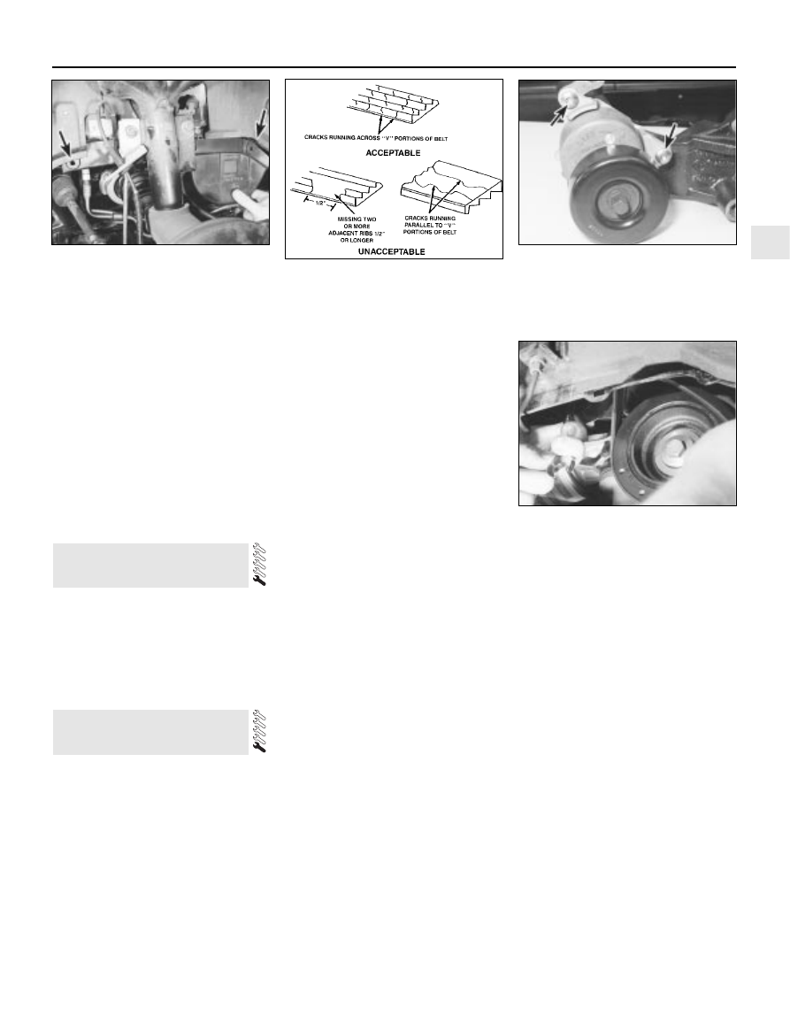
inside the wheel arch (see illustration).
Using an inspection light or a small electric
torch, and rotating the engine when necessary
with a spanner applied to the crankshaft
pulley bolt, check the whole length of the
drivebelt for cracks, separation of the rubber,
and torn or worn ribs (see illustration). Also
check for fraying and glazing, which gives the
drivebelt a shiny appearance. Both sides of
the drivebelt should be inspected, which
means you will have to twist the drivebelt to
check the underside. Use your fingers to feel
the drivebelt where you can’t see it. If you are
in any doubt as to the condition of the
drivebelt, renew it (go to paragraph 7).

Drivebelt tension

The auxiliary drivebelt is tensioned by an
automatic tensioner; regular checks are not
required, and manual “adjustment” is not
possible.
If you suspect that the drivebelt is slipping
and/or running slack, or that the tensioner is
otherwise faulty, it must be renewed. To do
this, remove the drivebelt as described below,
then unbolt the tensioner (two Torx-type
screws accessible from underneath, via the
wheel arch) from the alternator mounting
bracket (see illustration). On fitting the new
tensioner, ensure it is aligned correctly on its
mountings, and tighten the screws to the
specified torque wrench setting.

Renewal

Open the bonnet. Jack up the front right-
hand side of the vehicle and support it
securely on an axle stand, remove the
roadwheel, then remove the auxiliary drivebelt
cover (two fasteners) from inside the wheel
arch.
If the existing drivebelt is to be refitted,
mark it, or note the maker’s markings on its
flat surface, so that it can be installed the
same way round.
Reaching up between the body and the
engine (above and to the rear of the
crankshaft pulley), apply a spanner to the
hexagon in the centre of the automatic
tensioner’s pulley. Rotate the tensioner pulley
clockwise to release its pressure on the
drivebelt, then slip the drivebelt off the
crankshaft pulley, and release the tensioner
again  (see illustration). Working from the
wheel arch or engine compartment as
necessary, and noting its routing, slip the
drivebelt off the remaining pulleys and
withdraw it.
10 Check all the pulleys, ensuring that their
grooves are clean, and removing all traces of
oil and grease. Check that the tensioner
works properly, with strong spring pressure

11 Auxiliary drivebelt check and

renewal

10 Seat belt check

1•13

1

11.9  Rotate the tensioner pulley clockwise

to release its pressure on the drivebelt,

then slip the drivebelt off the crankshaft

pulley

11.3  Removing the auxiliary drivebelt

cover - it is secured by a fastener at each

end (arrowed) - from inside the right-hand

front wheel arch

11.4  Check the auxiliary drivebelt for signs

of wear like these. Very small cracks across

the drivebelt ribs are acceptable. If the

cracks are deep, or if the drivebelt looks

worn or damaged in any other way, renew it

11.6  The auxiliary drivebelt is tensioned by

an automatic tensioner; Torx screws

(arrowed) secure it to alternator mounting

bracket

Every 10 000 miles

being felt when its pulley is rotated clockwise,
and a smooth return to the limit of its travel
when released.
11 If the original drivebelt is being refitted,
use the marks or notes made on removal, to
ensure that it is installed to run in the same
direction as it was previously. To fit the
drivebelt, arrange it on the grooved pulleys so
that it is centred in their grooves, and not
overlapping their raised sides (note that the
flat surface of the drivebelt is engaged on the
idler, tensioner and water pump pulleys) and
routed correctly (see illustrations). Start at
the top, and work down to finish at the
crankshaft pulley; rotate the tensioner pulley
clockwise, slip the drivebelt onto the
crankshaft pulley, then release the tensioner
again.
12 Using a spanner applied to the crankshaft
pulley bolt, rotate the crankshaft through at
least two full turns clockwise to settle the
drivebelt on the pulleys, then check that the
drivebelt is properly installed.
13 Refit the auxiliary drivebelt cover and
roadwheel, then lower the vehicle to the
ground.

Caution: Renewal of air
conditioning hoses must be left
to a dealer service department or

air conditioning specialist who has the
equipment to depressurise the system

safely. Never remove air conditioning
components or hoses until the system has
been depressurised.

General

High temperatures in the engine
compartment can cause the deterioration of
the rubber and plastic hoses used for engine,
accessory and emission systems operation.
Periodic inspection should be made for
cracks, loose clamps, material hardening and
leaks.
Carefully check the large top and bottom
radiator hoses, along with the other smaller-
diameter cooling system hoses and metal
pipes; do not forget the heater hoses/pipes
which run from the engine to the bulkhead,
and those to the engine oil cooler (where
fitted). Inspect each hose along its entire
length, replacing any that is cracked, swollen
or shows signs of deterioration. Cracks may
become more apparent if the hose is
squeezed (see illustration). If you are using
non-Ford specification antifreeze, and so
have to renew the coolant every two years or
so, it’s a good idea to renew the hoses at that
time, regardless of their apparent condition.
Make sure that all hose connections are
tight. A leak in the cooling system will usually
show up as white- or rust-coloured deposits
on the areas adjoining the leak; if the spring
clamps that are used to secure the hoses in
this system appear to be slackening, they
should be renewed to prevent the possibility
of leaks.
Some other hoses are secured to their

fittings with clamps. Where clamps are used,
check to be sure they haven’t lost their
tension, allowing the hose to leak. If clamps
aren’t used, make sure the hose has not
expanded and/or hardened where it slips over
the fitting, allowing it to leak.

12 Underbonnet check for fluid

leaks and hose condition

1•14

11.11A  When installing the auxiliary

drivebelt, make sure that it is centred - it

must not overlap either edge of the

grooved pulleys

11.11B  Auxiliary drivebelt routing

1  Power steering pump
2  Idler pulley
3  Alternator

4  Automatic tensioner
5  Air conditioning 

compressor (when fitted)

6  Crankshaft pulley
7  Water pump pulley

12.2  Hoses, like drivebelts, have a habit of

failing at the worst possible time - to

prevent the inconvenience of a blown

radiator or heater hose, inspect them

carefully as shown here

Every 10 000 miles

Check all fluid reservoirs, filler caps, drain
plugs and fittings etc, looking for any signs of
leakage of oil, transmission and/or brake
hydraulic fluid, coolant and power steering
fluid. If the vehicle is regularly parked in the
same place, close inspection of the ground
underneath it will soon show any leaks; ignore
the puddle of water which will be left if the air
conditioning system is in use. As soon as a
leak is detected, its source must be traced
and rectified. Where oil has been leaking for
some time, it is usually necessary to use a
steam cleaner, pressure washer or similar, to
clean away the accumulated dirt, so that the
exact source of the leak can be identified.

Vacuum hoses

It’s quite common for vacuum hoses,
especially those in the emissions system, to
be colour-coded, or to be identified by
coloured stripes moulded into them. Various
systems require hoses with different wall
thicknesses, collapse resistance and
temperature resistance. When renewing
hoses, be sure the new ones are made of the
same material.
Often the only effective way to check a
hose is to remove it completely from the
vehicle. If more than one hose is removed, be
sure to label the hoses and fittings to ensure
correct installation.
When checking vacuum hoses, be sure to
include any plastic T-fittings in the check.
Inspect the fittings for cracks, and check the
hose where it fits over the fitting for distortion,
which could cause leakage.
A small piece of vacuum hose (quarter-inch
inside diameter) can be used as a
stethoscope to detect vacuum leaks. Hold
one end of the hose to your ear, and probe
around vacuum hoses and fittings, listening
for the “hissing” sound characteristic of a
vacuum leak. 

Warning: When probing with the
vacuum hose stethoscope, be
very careful not to come into
contact with moving engine

components such as the auxiliary
drivebelt, radiator electric cooling fan, etc.

Fuel hoses

Warning: There are certain
precautions which must be taken
when inspecting or servicing fuel

system components. Work in a well-
ventilated area, and do not allow open
flames (cigarettes, appliance pilot lights,
etc.) or bare light bulbs near the work
area. Mop up any spills immediately, and
do not store fuel-soaked rags where they
could ignite.
10 Check all fuel hoses for deterioration and
chafing. Check especially for cracks in areas
where the hose bends, and also just before
fittings, such as where a hose attaches to the
fuel filter.
11 High-quality fuel line, usually identified by
the word “Fluoroelastomer” printed on the

hose, should be used for fuel line renewal.
Never, under any circumstances, use
unreinforced vacuum line, clear plastic tubing
or water hose for fuel lines.
12 Spring-type clamps are commonly used
on fuel lines. These clamps often lose their
tension over a period of time, and can be
“sprung” during removal. Replace all
spring-type clamps with screw clamps
whenever a hose is replaced.

Metal lines

13 Sections of metal piping are often used
for fuel line between the fuel filter and the
engine. Check carefully to be sure the piping
has not been bent or crimped, and that cracks
have not started in the line.
14 If a section of metal fuel line must be
renewed, only seamless steel piping should
be used, since copper and aluminium piping
don’t have the strength necessary to
withstand normal engine vibration.
15 Check the metal brake lines where they
enter the master cylinder and ABS hydraulic
unit (if used) for cracks in the lines or loose
fittings. Any sign of brake fluid leakage calls
for an immediate and thorough inspection of
the brake system.

With the vehicle parked on level ground,
apply the handbrake firmly and open the
bonnet. Using an inspection light or a small
electric torch, check all visible wiring within
and beneath the engine compartment.
What you are looking for is wiring that is
obviously damaged by chafing against sharp
edges, or against moving suspension/
transmission components and/or the auxiliary
drivebelt, by being trapped or crushed
between carelessly-refitted components, or
melted by being forced into contact with the
hot engine castings, coolant pipes, etc. In
almost all cases, damage of this sort is
caused in the first instance by incorrect
routing on reassembly after previous work has
been carried out.
Depending on the extent of the problem,
damaged wiring may be repaired by rejoining
the break or splicing-in a new length of wire,
using solder to ensure a good connection,
and remaking the insulation with adhesive
insulating tape or heat-shrink tubing, as
appropriate. If the damage is extensive, given
the implications for the vehicle’s future
reliability, the best long-term answer may well
be to renew that entire section of the loom,
however expensive this may appear.
When the actual damage has been
repaired, ensure that the wiring loom is re-
routed correctly, so that it is clear of other
components, and not stretched or kinked, and
is secured out of harm’s way using the plastic
clips, guides and ties provided.
Check all electrical connectors, ensuring

that they are clean, securely fastened, and
that each is locked by its plastic tabs or wire
clip, as appropriate. If any connector shows
external signs of corrosion (accumulations of
white or green deposits, or streaks of “rust”),
or if any is thought to be dirty, it must be
unplugged and cleaned using electrical
contact cleaner. If the connector pins are
severely corroded, the connector must be
renewed; note that this may mean the renewal
of that entire section of the loom - see your
local Ford dealer for details.
If the cleaner completely removes the
corrosion to leave the connector in a
satisfactory condition, it would be wise to
pack the connector with a suitable material
which will exclude dirt and moisture,
preventing the corrosion from occurring
again; a Ford dealer may be able to
recommend a suitable product.
Check the condition of the battery
connections - remake the connections or
renew the leads if a fault is found (see Chap-
ter 5). Use the same techniques to ensure that
all earth points in the engine compartment
provide good electrical contact through clean,
metal-to-metal joints, and that all are securely
fastened. (In addition to the earth connection
at the engine lifting eye, and that from the
transmission to the body/battery, there are
one or two earth points behind each headlight
assembly, and one below the power steering
fluid reservoir.)
Refer to Section 31 for details of spark plug
(HT) lead checks.

Warning: The air conditioning
system is under high pressure.
Do not loosen any fittings or
remove any components until

after the system has been discharged. Air
conditioning refrigerant must be properly
discharged into an approved type of
container, at a dealer service department
or an automotive air conditioning repair
facility capable of handling R134a
refrigerant. Always wear eye protection
when disconnecting air conditioning
system fittings.

The following maintenance checks should
be performed on a regular basis, to ensure
that the air conditioner continues to operate at
peak efficiency:
(a) Check the auxiliary drivebelt. If it’s worn

or deteriorated, renew it (see Section 11).

(b) Check the system hoses. Look for cracks,

bubbles, hard spots and deterioration.
Inspect the hoses and all fittings for oil
bubbles and seepage. If there’s any
evidence of wear, damage or leaks, renew
the hose(s).

(c) Inspect the condenser fins for leaves,

insects and other debris. Use a “fin

14 Air conditioning system

check

13 Engine compartment wiring

check

1•15

1

Every 10 000 miles

comb” or compressed air to clean the
condenser. 

Warning: Wear eye protection
when using compressed air!

(d) Check that the drain tube from the front

of the evaporator is clear - note that it is
normal to have clear fluid (water) dripping
from this while the system is in operation,
to the extent that quite a large puddle can
be left under the vehicle when it is parked.

It’s a good idea to operate the system for

about 30 minutes at least once a month,
particularly during the winter. Long term
non-use can cause hardening, and
subsequent failure, of the seals.
Because of the complexity of the air
conditioning system and the special
equipment necessary to service it, in-depth
fault diagnosis and repairs are not included in
this manual. For more complete information
on the air conditioning system, refer to the
Haynes  Automotive Heating and Air
Conditioning Manual
.
The most common cause of poor cooling is
simply a low system refrigerant charge. If a
noticeable drop in cool air output occurs, the
following quick check will help you determine
if the refrigerant level is low.
Warm the engine up to normal operating
temperature.
Place the air conditioning temperature
selector at the coldest setting, and put the
blower at the highest setting. Open the doors
- to make sure the air conditioning system
doesn’t cycle off as soon as it cools the
passenger compartment.
With the compressor engaged - the clutch
will make an audible click, and the centre of
the clutch will rotate - feel the inlet and outlet
pipes at the compressor. One side should be
cold, and one hot. If there’s no perceptible
difference between the two pipes, there’s
something wrong with the compressor or the
system. It might be a low charge - it might be
something else. Take the vehicle to a dealer
service department or an automotive air
conditioning specialist.

Make sure that you have all the necessary
tools before you begin this procedure (see
illustration)
. You should also have plenty of
rags or newspapers handy, for mopping up
any spills.
To avoid any possibility of scalding, and to
protect yourself from possible skin irritants
and other harmful contaminants in used
engine oils, it is advisable to wear gloves
when carrying out this work.
Access to the underside of the vehicle is
greatly improved if the vehicle can be lifted on
a hoist, driven onto ramps, or supported by
axle stands. 

Warning: Do not work under a
vehicle which is supported only
by an hydraulic or scissors-type
jack, or by bricks, blocks of
wood, etc.

If this is your first oil change, get under the
vehicle and familiarise yourself with the
position of the engine oil drain plug, which is
located at the rear of the sump. The engine
and exhaust components will be warm during
the actual work, so try to anticipate any
potential problems while the engine and
accessories are cool.
The oil should preferably be changed when
the engine is still fully warmed-up to normal
operating temperature, just after a run (the
needle on the temperature gauge should be in
the “Normal” sector of the gauge); warm oil
and sludge will flow out more easily. Park the
vehicle on firm, level ground, apply the
handbrake firmly, then select 1st or reverse
gear (manual transmission) or the “P” position
(automatic transmission). Open the bonnet
and remove the engine oil filler cap from the
cylinder head cover, then remove the oil level
dipstick from its tube (see Section 3).
Raise the front of the vehicle, and support it
securely on axle stands. Remove the front
right-hand roadwheel to provide access to the
oil filter; if the additional working clearance is
required, remove also the auxiliary drivebelt
cover (two fasteners). 

15 Engine oil and filter change

1•16

15.1  These tools are required when

changing the engine oil and filter

Drain pan - It should be fairly shallow in
depth, but wide to prevent spills
Rubber gloves - When removing the drain
plug and filter, it is inevitable that you will get
oil on your hands (the gloves will prevent
burns from hot oil)
Breaker bar - Sometimes the oil drain plug
is pretty tight, and a long breaker bar is
needed to loosen it
Socket - To be used with the breaker bar
or a ratchet (must be the correct size to fit the
drain plug)
Filter wrench - This is a metal band-type
wrench, which requires clearance around the
filter to be effective
Filter wrench - This type fits on the
bottom of the filter, and can be turned with a
ratchet or breaker bar (different size wrenches
are available for different types of filters)

15.7  Use the correct-size spanner or

socket to remove the oil drain plug and

avoid rounding it off

15.9  Since the oil filter is usually on very

tight, you’ll need a special wrench for

removal. DO NOT use the wrench to

tighten the new filter. Pack rag under the

filter before removal to minimise the mess

Every 10 000 miles

Frequent oil changes are the
best preventive maintenance
the home mechanic can give
the engine, because ageing

oil becomes diluted and contaminated,
which leads to premature engine wear.

Note: It is
antisocial and
illegal to dump
oil down the
drain. To find
the location of
your local oil
recycling bank,
call this
number free.


Content   ..  5  6  7  8   ..