Ford Mondeo (petrol engines). Manual - part 5
 

  Index      Ford     Ford Mondeo - service and repair manual (petrol engines)


Search            


Content   ..  3  4  5  6   ..


Ford Mondeo (petrol engines). Manual - part 5


1•5

1

Maintenance procedures

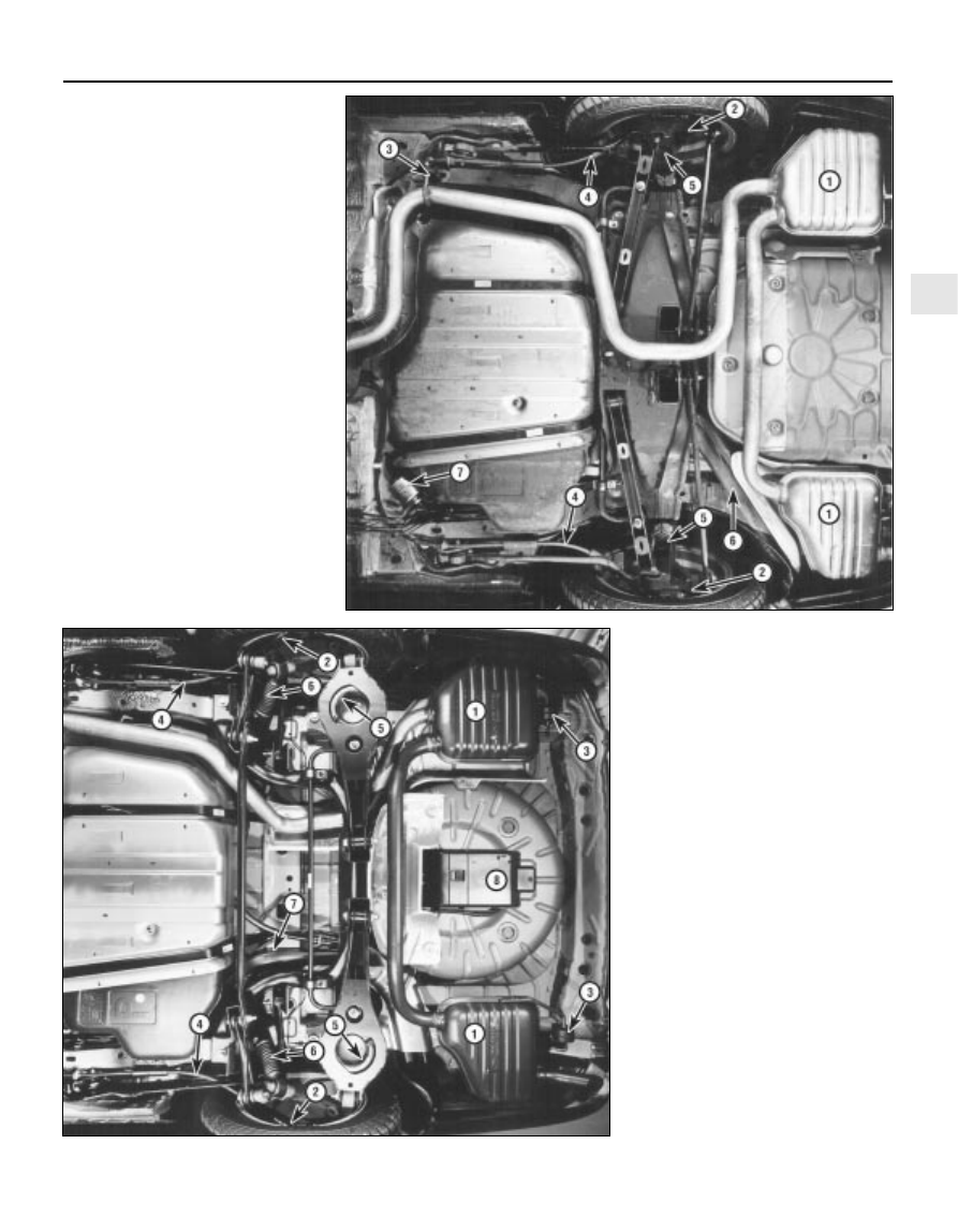
Rear underbody view - Saloon and

Hatchback models

1  Silencers (Section 21)
2  Rear brakes (Section 23)
3  Exhaust system rubber mounting 

(Section 21)

4  Handbrake cables (Section 23)
5  Suspension struts and springs 

(Section 19)

6  Fuel tank filler neck (Section 22)
7  Fuel filter (Section 33)

Rear underbody view - Estate models

1  Silencers (Section 21)
2  Rear brakes (Section 23)
3  Exhaust system rubber mounting

(Section 21)

4  Handbrake cables (Section 23)
5  Suspension springs (Section 19)
6  Suspension shock absorbers (Section 19)
7  Fuel tank filler neck (Section 22)
8  Evaporative emissions control system 

charcoal canister (Chapter 6)

This Chapter is designed to help the home

mechanic maintain the Ford Mondeo models
for peak performance, economy, safety and
long life.

On the following pages are Sections

dealing specifically with each item on the
maintenance schedule. Visual checks,
adjustments, component replacement and
other helpful items are included. Refer to the
accompanying illustrations of the engine
compartment and the underside of the vehicle
for the location of various components.

Servicing your Mondeo in accordance with

the mileage/time maintenance schedule and
the following Sections will provide it with a
planned maintenance programme, which
should result in a long and reliable service life.
This is a comprehensive plan, so maintaining
some items but not others at the specified
service intervals will not produce the same
results.

As you service your Mondeo, you will

discover that many of the procedures can -
and should - be grouped together, because of
the nature of the particular procedure you’re
performing, or because of the close proximity
to one another of two otherwise-unrelated
components.

For example, if the vehicle is raised for any

reason, you should inspect the exhaust,
suspension, steering and fuel systems while
you’re under the vehicle. When you’re
checking the tyres, it makes good sense to
check the brakes and wheel bearings,
especially if the roadwheels have already
been removed.

Finally, let’s suppose you have to borrow or

hire a torque wrench. Even if you only need to
tighten the spark plugs, you might as well
check the torque of as many critical fasteners
as time allows.

The first step of this maintenance

programme is to prepare yourself before the
actual work begins. Read through all the
Sections which are relevant to the procedures
you’re planning to carry out, then make a list
of, and gather together, all the parts and tools
you will need to do the job. If it looks as if you
might run into problems during a particular
segment of some procedure, seek advice
from your local parts man or dealer service
department.

Ford state that, where antifreeze to

specification ESD-M97B-49-A (the type with
which the vehicle’s cooling system would
have been filled on production at the factory)
is used, it will last the lifetime of the vehicle.

This is subject to it being used in the
recommended concentration, unmixed with
any other type of antifreeze or additive, and
topped-up when necessary using only that
antifreeze mixed 50/50 with clean water. If any
other type of antifreeze is added, the lifetime
guarantee no longer applies; to restore the
lifetime protection, the system must be
drained and thoroughly reverse-flushed
before fresh coolant mixture is poured in.

If the vehicle’s history (and therefore the

quality of the antifreeze in it) is unknown,
owners who wish to follow Ford’s
recommendations are advised to drain and
thoroughly reverse-flush the system, as
outlined in Section 28, before refilling with
fresh coolant mixture. If the appropriate
quality of antifreeze is used, the coolant can
then be left for the life of the vehicle.

If any antifreeze other than Ford’s is to be

used, the coolant must be renewed at regular
intervals to provide an equivalent degree of
protection; the conventional recommendation
is to renew the coolant every two years.

The above assumes the use of a mixture (in

exactly the specified concentration) of clean,
soft water and of antifreeze to Ford’s
specification or equivalent. It is also assumed
that the cooling system is maintained in a
scrupulously-clean condition, by ensuring that
only clean coolant is added on topping-up,
and by thorough reverse-flushing whenever
the coolant is drained (Section 28).

2 Coolant renewal

1 Introduction

1•6

Weekly checks

Weekly checks

General

Fluids are an essential part of the
lubrication, cooling, braking and other
systems. Because these fluids gradually
become depleted and/or contaminated during
normal operation of the vehicle, they must be
periodically replenished. See “Lubricants and
fluids and capacities” 
at the beginning of this
Chapter before adding fluid to any of the
following components. Note: The vehicle
must be on level ground before fluid levels can
be checked.

Engine oil

The engine oil level is checked with a
dipstick located at the front of the engine; it
can be identified by its yellow/black plastic
grip (see illustration). The dipstick extends
through a metal tube, from which it protrudes
down into the sump at the bottom of the
engine.
The oil level should be checked before the
vehicle is driven, or about 5 minutes after the
engine has been switched off.

Pull the dipstick from the tube, and wipe all
the oil from the end with a clean rag or paper
towel; note the dipstick’s maximum and
minimum levels, indicated by notches (see

illustration). Insert the clean dipstick all the way
back into its metal tube, and pull it out again.
Observe the oil on the end of the dipstick; its
level should be between these two notches.
Do not allow the level to drop below the
minimum level notch, or oil starvation may
cause engine damage. Conversely, overfilling
the engine (adding oil above the maximum
level notch) may cause oil-fouled spark plugs,
oil leaks or oil seal failures.
The yellow/black plastic oil filler cap is
screwed into the left-hand front end of the

3 Fluid level checks

3.2  The engine oil dipstick (arrowed) is

located at the front of the engine - note

yellow/black plastic grip

3.4  The oil level should be at or near the

maximum level notch (A) - if not, add

enough oil to correct the level. It takes

approximately 0.5 to 1.0 litre of oil to raise

the level from the minimum level notch (B)

to the maximum

If the level is checked
immediately after driving the
vehicle, some of the oil will
remain in the engine upper

components, producing an inaccurate
dipstick reading.

cylinder head cover; unscrew it to add oil (see
illustration)
. When topping-up, use only the
correct grade and type of oil, as given in the
Specifications Section of this Chapter; use a
funnel if necessary to prevent spills. It takes
approximately 0.5 to 1.0 litre of oil to raise the
level from the dipstick’s minimum level notch
to its maximum level notch. After adding the
oil, refit the filler cap hand-tight. Start the
engine, and allow it to idle while the oil is
redistributed around the engine - while you
are waiting, look carefully for any oil leaks,
particularly around the oil filter or drain plug.
Stop the engine; check the oil level again,
after the oil has had enough time to drain from
the upper block and cylinder head galleries.
Checking the oil level is an important
preventive maintenance step. A continually-
dropping oil level indicates oil leakage through
damaged seals and from loose connections,
or oil consumption past worn piston rings or
valve guides. If the oil looks milky in colour, or
has water droplets in it, the cylinder head
gasket may be blown - the engine’s
compression pressure should be checked
immediately (see Chapter 2A). The condition
of the oil should also be checked. Each time
you check the oil level, slide your thumb and
index finger up the dipstick before wiping off
the oil. If you see small dirt or metal particles
clinging to the dipstick, the oil should be
changed (Section 15).

Coolant

Warning: Do not allow antifreeze
to come in contact with your skin
or painted surfaces of the

vehicle. Flush contaminated areas
immediately with plenty of water. Don’t
store new coolant, or leave old coolant
lying around, where it’s accessible to
children or pets - they’re attracted by its
sweet smell. Ingestion of even a small
amount of coolant can be fatal! Wipe up
garage-floor and drip-pan spills
immediately. Keep antifreeze containers
covered, and repair cooling system leaks
as soon as they’re noticed.

All vehicles covered by this manual are
equipped with a sealed, pressurised cooling
system. A translucent plastic expansion tank,
located on the right-hand side of the engine
compartment, is connected by a hose to the
thermostat housing. As the coolant heats up
during engine operation, surplus coolant
passes through the connecting hose into the
expansion tank; a connection to the radiator
bottom hose union allows coolant to circulate
through the tank and back to the water pump,
thus purging any air from the system. As the
engine cools, the coolant is automatically
drawn back into the cooling system’s main
components, to maintain the correct level.
While the coolant level must be checked
regularly, remember therefore that it will vary
with the temperature of the engine. When the
engine is cold, the coolant level should be
between the “MAX” and “MIN” level lines on
the tank, but once the engine has warmed up,
the level may rise to above the “MAX” level
line.
10 For an accurate check of the coolant
level, the engine must be cold. The level must
be between the “MAX” and “MIN” level lines
on the tank (see illustration). If it is below the
“MIN” level line, the coolant must be topped-
up as follows.
11 First prepare a sufficient quantity of
coolant mixture, using clean, soft water and
antifreeze of the recommended type, in the
specified mixture ratio. If you are using
antifreeze to Ford’s specification or equivalent
(see the note at the beginning of Section 2 of
this Chapter), mix equal quantities of water
and antifreeze to produce the 50/50 mixture
ratio specified when topping-up; if using any
other type of antifreeze, follow its
manufacturer’s instructions to achieve the
correct ratio. If only a small amount of coolant
is required to bring the system up to the
proper level, plain water can be used, but
repeatedly doing this will dilute the
antifreeze/water solution in the system,
reducing the protection it should provide
against freezing and corrosion. To maintain

the specified antifreeze/water ratio, it is
essential to top-up the coolant level with the
correct mixture, as described here. Use only
ethylene/glycol type antifreeze, and do not
use supplementary inhibitors or additives. 

Warning: Never remove the
expansion tank filler cap when
the engine is running, or has just

been switched off, as the cooling system
will be hot, and the consequent escaping
steam and scalding coolant could cause
serious injury.

12 If topping-up is necessary, wait until the
system has cooled completely (or at least 10
minutes after switching off the engine, if lack
of time means it is absolutely necessary to
top-up while the engine may still be warm).
Wrap a thick cloth around the expansion tank
filler cap, and unscrew it one full turn. If any
hissing is heard as steam escapes, wait until
the hissing ceases, indicating that pressure is
released, then slowly unscrew the filler cap
until it can be removed. If more hissing
sounds are heard, wait until they have
stopped before unscrewing the filler cap
completely. At all times, keep your face,
hands and other exposed skin well away from
the filler opening.
13 When the filler cap has been removed,
add coolant to bring the level up to the “MAX”
level line (see illustration). Refit the cap,
tightening it securely.
14 With this type of cooling system, the
addition of coolant should only be necessary at
very infrequent intervals. If topping-up is
regularly required, or if the coolant level drops
within a short time after replenishment, there
may be a leak in the system. Inspect the
radiator, hoses, expansion tank filler cap,
radiator drain plug and water pump. If no leak is
evident, have the filler cap and the entire
system pressure-tested by your dealer or
suitably-equipped garage; this will usually show
up a small leak not otherwise visible. If
significant leakage is found at any time, use an
antifreeze hydrometer to check the con-
centration of antifreeze remaining in the coolant.

1•7

1

3.13  Remove the cap to add coolant only

when the engine is cold - top-up to the

“MAX” level line using the specified

coolant mixture

3.6  The yellow/black oil filler cap is

screwed into the cylinder head cover.

Always make sure the area around the

opening is clean before unscrewing the

cap, to prevent dirt from contaminating the

engine

3.10  The cooling system expansion tank is

located on the right-hand side of the

engine compartment. The coolant level

must be between the tank “MAX” and

“MIN” level lines (arrowed) when the

engine is cold

Weekly checks

15 Coolant hydrometers are available at
most automotive accessory shops. If the
specific gravity of a sample taken from the
expansion tank (when the engine is switched
off and fully cooled down) is less than that
specified, the coolant mixture strength has
fallen below the minimum. If this is found,
either the coolant strength must be restored
by adding neat antifreeze to Ford’s
specification (if that is what is in the system)
or by draining and flushing the system, then
refilling it with fresh coolant mixture of the
correct ratio (if any other type of antifreeze is
being used).
16 When checking the coolant level, always
note its condition; it should be relatively clear.
If it is brown or rust-coloured, the system
should be drained, flushed and refilled. If
antifreeze has been used which does not
meet Ford’s specification, its corrosion
inhibitors will lose their effectiveness with
time; such coolant must be renewed regularly,
even if it appears to be in good condition,
usually at the intervals suggested at the
beginning of Section 2 of this Chapter.

Windscreen/tailgate and
headlight washer fluid

17 Fluid for the windscreen/tailgate washer
system (and where applicable the headlight
washer system) is stored in a plastic reservoir,
which is located at the right front corner of the
engine compartment. In milder climates, plain
water can be used to top-up the reservoir, but
the reservoir should be kept no more than
two-thirds full, to allow for expansion should
the water freeze. In colder climates, the use of
a specially-formulated windscreen washer
fluid, available at your dealer or any car
accessory shop, will help lower the freezing
point of the fluid (see illustration)Do not use
regular (engine) antifreeze - it will damage the
vehicle’s paintwork.

Battery electrolyte

18 On models not equipped with a sealed
battery (see Section 9), check the electrolyte
level of all six battery cells. The level must be
approximately 10 mm above the plates; this
may be shown by maximum and minimum
level lines marked on the battery’s casing (see

illustration). If the level is low, use a coin to
release the filler/vent cap, and add distilled
water. Install and securely retighten the cap. 

Caution: Overfilling the cells may
cause electrolyte to spill over
during periods of heavy charging,
causing corrosion or damage.

Refer also to the warning at the beginning
of Section 9.

Brake fluid

19 The brake fluid reservoir is located on the
top of the brake master cylinder, which is
attached to the front of the vacuum servo unit.
The “MAX” and “MIN” marks are indicated on
the side of the translucent reservoir, and the
fluid level should be maintained between
these marks at all times (see illustration).
20 The brake fluid inside the reservoir is
readily visible. With the vehicle on level
ground, the level should normally be on or just
below the “MAX” mark.
21 Progressive wear of the brake pads and
brake shoe linings causes the level of the
brake fluid to gradually fall; however, when
the brake pads are renewed, the original level
of the fluid is restored. It is not therefore
necessary to top-up the level to compensate
for this minimal drop, but the level must never
be allowed to fall below the minimum mark.
22 If topping-up is necessary, first wipe the
area around the filler cap with a clean rag
before removing the cap. When adding fluid,
pour it carefully into the reservoir, to avoid
spilling it on surrounding painted surfaces
(see illustration). Be sure to use only the
specified hydraulic fluid (see “Lubricants,
fluids and capacities” 
at the start of this
Chapter) since mixing different types of fluid
can cause damage to the system. 

Warning: Brake hydraulic fluid
can harm your eyes and damage
painted surfaces, so use extreme
caution when handling and

pouring it. Wash off spills immediately with
plenty of water. Do not use fluid that has
been standing open for some time, as it
absorbs moisture from the air. Excess

moisture can cause corrosion and a
dangerous loss of braking effectiveness.
23 When adding fluid, it is a good idea to
inspect the reservoir for contamination. The
system should be drained and refilled if
deposits, dirt particles or contamination are
seen in the fluid.
24 After filling the reservoir to the correct
level, make sure that the cap is refitted
securely, to avoid leaks and the entry of
foreign matter.
25 If the reservoir requires repeated
replenishing to maintain the correct level, this
is an indication of an hydraulic leak
somewhere in the system, which should be
investigated immediately.

Power steering fluid

26 See Section 5 of this Chapter.

Periodic inspection of the tyres may spare
you from the inconvenience of being stranded
with a flat tyre. It can also provide you with
vital information regarding possible problems
in the steering and suspension systems
before major damage occurs.
The original tyres on this vehicle are
equipped with tread wear indicator (TWI)
bands, which will appear when the tread
depth reaches approximately 1.6 mm. Most
tyres have a mark around the tyre at regular
intervals to indicate the location of the tread

4 Tyre and tyre pressure checks

1•8

3.17  Topping-up the windscreen washer

reservoir

3.18  On non-sealed batteries, keep the

electrolyte level of all the cells in the

battery between the maximum and

minimum levels (arrowed) - ie, 10 mm

above the plates. Use only distilled water,

and never overfill

3.19  Brake fluid reservoir, showing “MAX”

and “MIN” marks

3.22  Topping-up the brake fluid reservoir

Weekly checks


Content   ..  3  4  5  6   ..