Ford Orion. Manual - part 8
flap inside the air cleaner inlet. When the
ambient air temperature is below a
predetermined level, the flap admits air
heated from the exhaust manifold shroud; as
the ambient temperature rises, the flap opens
to admit more cool air from the engine
compartment until eventually it is fully open. A
similar system is used on CVH engines,
except that a vacuum actuator modifies any
opening or closing action of the temperature
sensor on the flap valve, according to the level
of the inlet manifold vacuum under running
conditions.
HCS engines
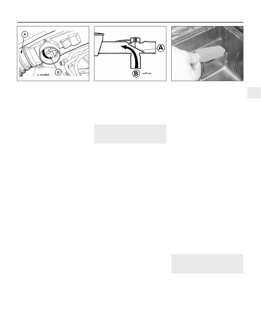
8 This check must be made when the engine
is cold. Detach and remove the air cleaner
inlet trunking. Examine the position of the
check valve within the duct. When the
underbonnet air temperature is below 28ºC,
the valve must be open to allow hot air to
enter the filter (see illustration).
9 Refit the inlet trunking. Start the engine and
run it until it reaches its normal operating
temperature, then stop the engine, remove
the inlet trunking and check that the valve has
closed off the air passage from the exhaust
and opened the main (cool) air inlet.
10 If the flap does not operate correctly,
check that it is not seized. Apart from this
there is no adjustment possible, and the unit
should be renewed if faulty. Refit the air inlet
trunking on completion.
CVH engines
11 This check must be made when the
engine is cold. Disconnect the main air inlet
duct, and visibly check that the flap to the
hot-air inlet is closed (i.e. open to the passage
of cold air).
12 Start the engine, and check that with the
engine idling, the hot-air inlet is open to allow
warm air from the exhaust manifold area to
enter the air cleaner. If the flap operates as
described, it is functioning correctly (see
illustration).
13 If the flap fails to operate as described,
check the condition of the vacuum pipe and
its connections, and check that the flap valve
has not seized. If these are in order, either the
temperature sensor or vacuum actuator is
faulty, and a new air cleaner assembly must
be obtained. Refit the main air duct on
completion.
30 Positive Crankcase
Ventilation (PCV) system
check and filter cleaning
1
1 The function of the crankcase ventilation
system is to reduce the emission of unburned
hydrocarbons from the crankcase, and to
minimise the formation of oil sludge. By
ensuring that a depression is created in the
crankcase under most operating conditions,
particularly at idle, and by positively inducing
fresh air into the system, the oil vapours and
“blow-by” gases collected in the crankcase
are drawn from the crankcase, through the air
cleaner or oil separator, into the inlet tract, to
be burned by the engine during normal
combustion.
2 On HCS engines, the system consists of a
vented oil filler cap (with an integral mesh
filter) and a hose connecting it to the oil
separator/engine breather valve connector on
the underside of the air cleaner housing. A
further hose leads from the adapter/filter to
the inlet manifold.
3 On CVH engines, a closed-circuit type
crankcase ventilation system is used, the
function of which is basically the same as that
described for the HCS engine type, but the
breather hose connects directly to the rocker
cover. The oil filler cap incorporates a
separate filter in certain applications.
4 On Zetec engines, the crankcase ventilation
system main components are the oil
separator mounted on the front (radiator) side
of the cylinder block/crankcase, and the
Positive Crankcase Ventilation (PCV) valve set
in a rubber grommet in the separator’s left-
hand upper end. The associated pipework
consists of a crankcase breather pipe and two
flexible hoses connecting the PCV valve to a
union on the left-hand end of the inlet
manifold, and a crankcase breather hose
connecting the cylinder head cover to the air
cleaner assembly. A small foam filter in the air
cleaner prevents dirt from being drawn
directly into the engine.
5 Check that all components of the system
are securely fastened, correctly routed (with
no kinks or sharp bends to restrict flow) and in
sound condition; renew any worn or damaged
components.
6 If oil leakage is noted, disconnect the
various hoses and pipes, and check that all
are clear and unblocked. Remove the air
cleaner assembly cover, and check that the
hose from the cylinder head cover to the air
cleaner housing is clear and undamaged.
7 Where fitted, the PCV valve is designed to
allow gases to flow out of the crankcase only,
so that a depression is created in the
crankcase under most operating conditions,
particularly at idle. Therefore, if either the oil
separator or the PCV valve are thought to be
blocked, they must be renewed (see Chapter
6). In such a case, however, there is nothing to
be lost by attempting to flush out the
blockage using a suitable solvent. The PCV
valve should rattle when shaken.
8 While the air filter element is removed (see
Section 29), wipe out the housing, and on
Zetec engines, withdraw the small foam filter
from its location in the rear right-hand corner
of the housing (see illustration). If the foam is
badly clogged with dirt or oil, it must be
cleaned by soaking it in a suitable solvent,
and allowed to dry before being refitted.
31 Oil filler cap check
1
1 On HCS engines, remove and inspect the
cap to ensure that it is in good condition, and
not blocked up with sludge.
2 Disconnect the hoses at the cap, and clean
the cap if necessary by brushing the inner
mesh filter with petrol, and blowing through
with light pressure from an air line. Renew the
cap if it is badly congested.
Every 30 000 miles
1•29
30.8 The PCV system foam filter is located
in the rear right-hand corner of the air
cleaner housing on Zetec engines
29.12 Air cleaner inlet and flap valve on
the CVH engine
A Flap open (cool air inlet closed)
B Warm air inlet
29.8 Air cleaner inlet and flap valve on the
HCS engine
A Main air cleaner inlet (cool air)
B Warm air duct (flap open)
1