Citroen C4 (2023 year). Manual in english - page 4
2. Instrument cluster
127
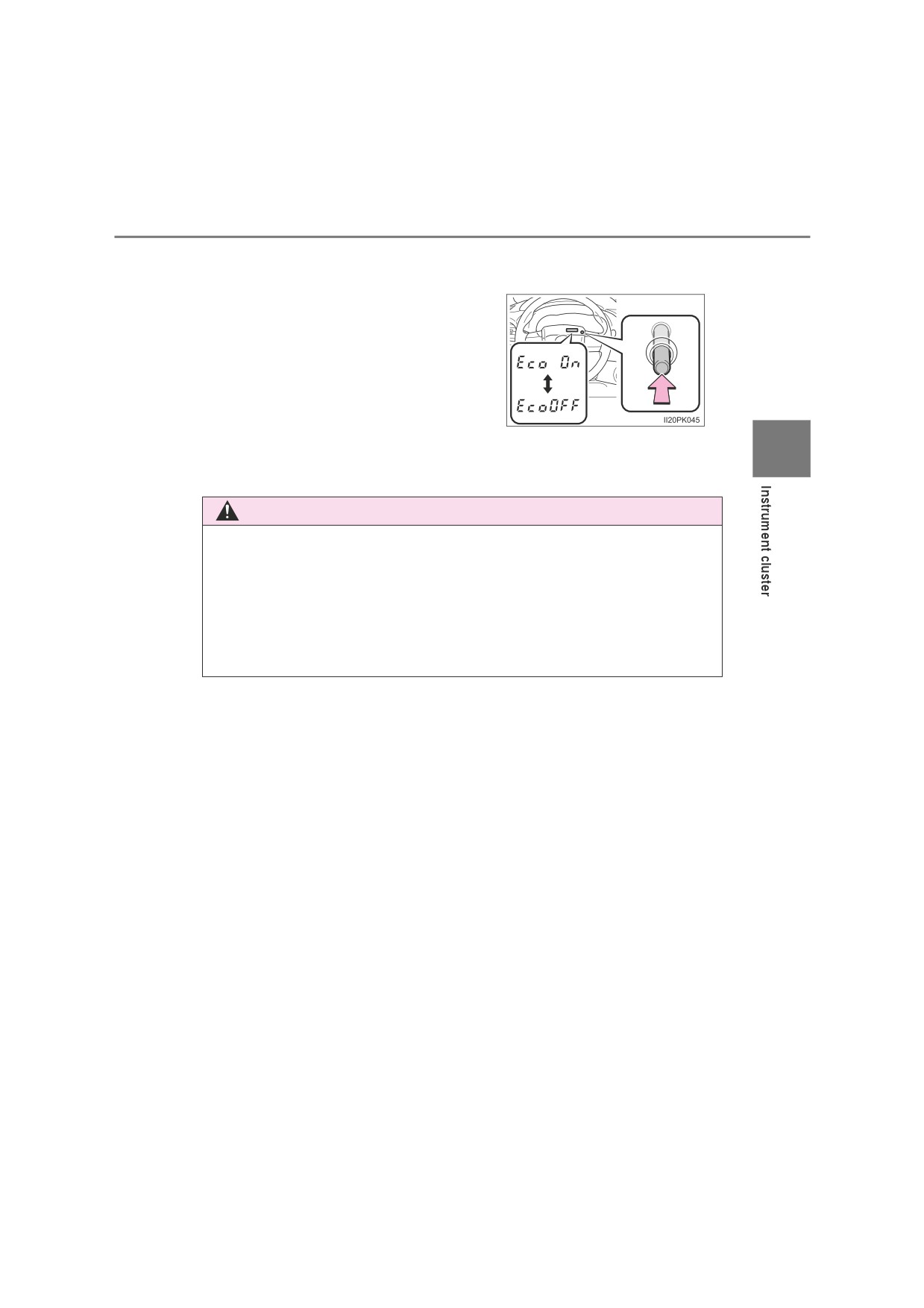
Eco Driving Indicator Light can be activated or deactivated.
Vehicles without multi-information display:
While the odometer is being displayed,
press and hold the odometer/trip meter
display change button to display the Eco
Driving Indicator Light customization
screen.
Press the odometer/trip meter display
change button to set Eco Driving Indicator
Light to on or off.
Press and hold the odometer/trip meter display change button
for more than
2
2 seconds to complete the setting.
Vehicles with multi-information display:P. 645
WARNING
■ If a safety system warning light does not come on
Should a safety system light such as ABS and the SRS warning light not
come on when you start the engine, this could mean that these systems are
not available to help protect you in an accident, which could result in death
or serious injury. Have the vehicle inspected by any authorized Toyota
retailer or Toyota authorized repairer, or any reliable repairer immediately if
this occurs.
128
2. Instrument cluster
Gauges and meters
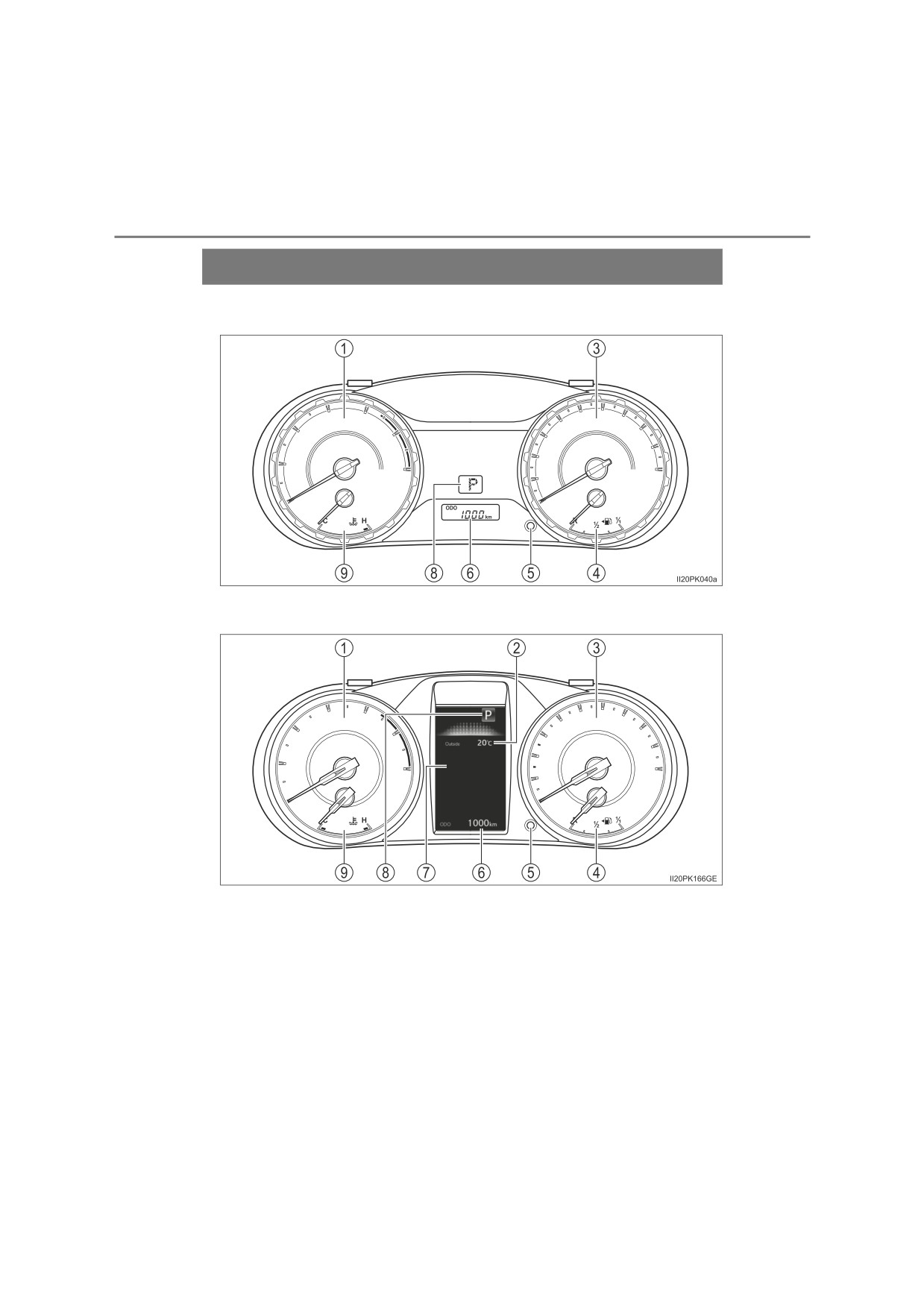
Vehicles without multi-information display
Vehicles with multi-information display
The units used on the speedometer and fuel gauge may differ depending
on the target region, and the positions of the outside temperature and shift
position indicators differ depending on vehicles.
2. Instrument cluster
129
1
Tachometer
Displays the engine speed in revolutions per minute.
2
Outside temperature
Displays the outside temperature. The temperature range that can be dis-
played is from -40C (-40F) to 50C (122F). The low outside temperature
indicator comes on when the ambient temperature is approximately 3C
(37F) or lower, and goes off when approximately 5C (41F) or higher.
(P. 125)
3
Speedometer
Displays the vehicle speed.
2
4
Fuel gauge
Displays the quantity of fuel remaining in the tank.
Odometer/trip meter display change button
5
P. 130
Odometer and trip meter
6
Odometer:
Displays the total distance the vehicle has been driven.
Trip meter:
Displays the distance the vehicle has been driven since the meter was last
reset. Trip meters A and B can be used to record and display different dis-
tances independently.
Multi-information display
7
Presents the driver with a variety of driving-related data. (P. 133)
Shift position and shift range (automatic transmission)
8
Displays the selected shift position or selected shift range. (P. 229)
Engine coolant temperature gauge
9
Displays the engine coolant temperature.
130
2. Instrument cluster
Changing the display
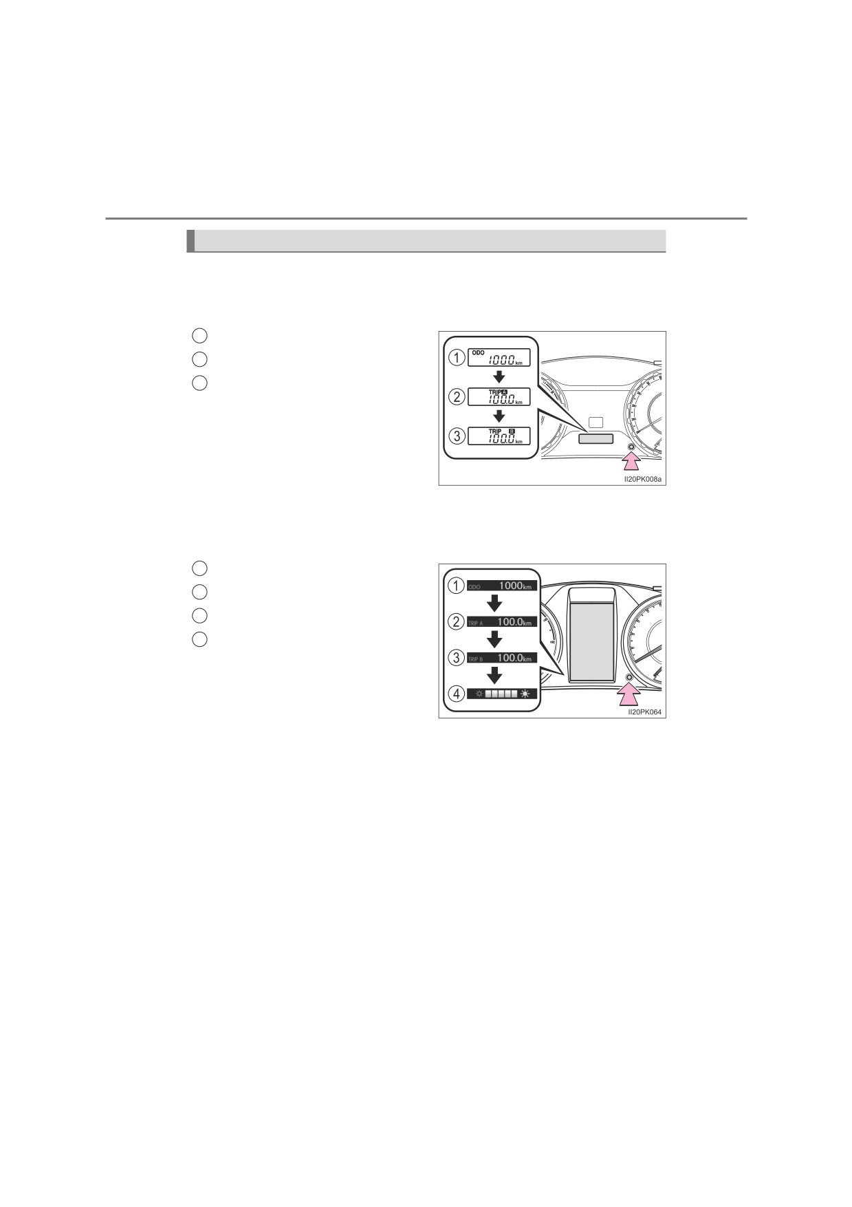
Vehicles without multi-information display
Pressing this button switches between odometer and trip meter dis-
plays.
1
Odometer
2
Trip meter A*
3
Trip meter B*
*: Pressing and holding the button
will reset the trip meter.
Vehicles with multi-information display
Pressing this button switches among odometer, trip meter and instru-
ment panel light control displays.
1
Odometer
2
Trip meter A*1
3
Trip meter B*1
4
Instrument panel light control
display*2
*1: Pressing and holding the button
will reset the trip meter.
*2: Pressing and holding the button
will adjust brightness of the instru-
ment panel lights.
2. Instrument cluster
131
■ The meters illuminate when
The engine switch is in the “ON” position (vehicles without smart entry & start
system) or IGNITION ON mode (vehicles with smart entry & start system).
■ The brightness of the instrument panel lights (vehicles with multi-infor-
mation display)
The instrument panel brightness levels when the tail lights are on and off can
be adjusted individually.
When the headlight switch is turned to on, the brightness will be reduced
slightly unless the instrument panel brightness level is set to the brightest set-
ting.
2
■ When disconnecting and reconnecting battery terminals
The trip meter data will be reset.
■ Outside temperature display
In the following situations, the correct outside temperature may not be dis-
played, or the display may take longer than normal to change:
● When the vehicle is stopped, or moving at low speeds (less than 25 km/h
[15 mph])
● When the outside temperature has changed suddenly (at the entrance/exit
of a garage, tunnel, etc.)
■ When “--” is displayed
The system may be malfunctioning. Take your vehicle to any authorized
Toyota retailer or Toyota authorized repairer, or any reliable repairer.
132
2. Instrument cluster
WARNING
■ The information display at low temperatures (vehicles with multi-infor-
mation display)
Allow the interior of the vehicle to warm up before using the liquid crystal
information display. At extremely low temperatures, the display monitor may
respond slowly, and display changes may be delayed.
For vehicles with automatic transmission: For example, there is a lag
between the driver’s shifting and the new gear number appearing on the
display. This lag could cause the driver to downshift again, causing rapid
and excessive engine braking and possibly an accident resulting in death or
injury.
NOTICE
■ To prevent damage to the engine and its components
●Do not let the indicator needle of the tachometer enter the red zone, which
indicates the maximum engine speed.
●The engine may be overheating if the engine coolant temperature gauge is
in the red zone (H). In this case, immediately stop the vehicle in a safe
place, and check the engine after it has cooled completely. (P. 608)
2. Instrument cluster
133
Multi-information display
Display contents
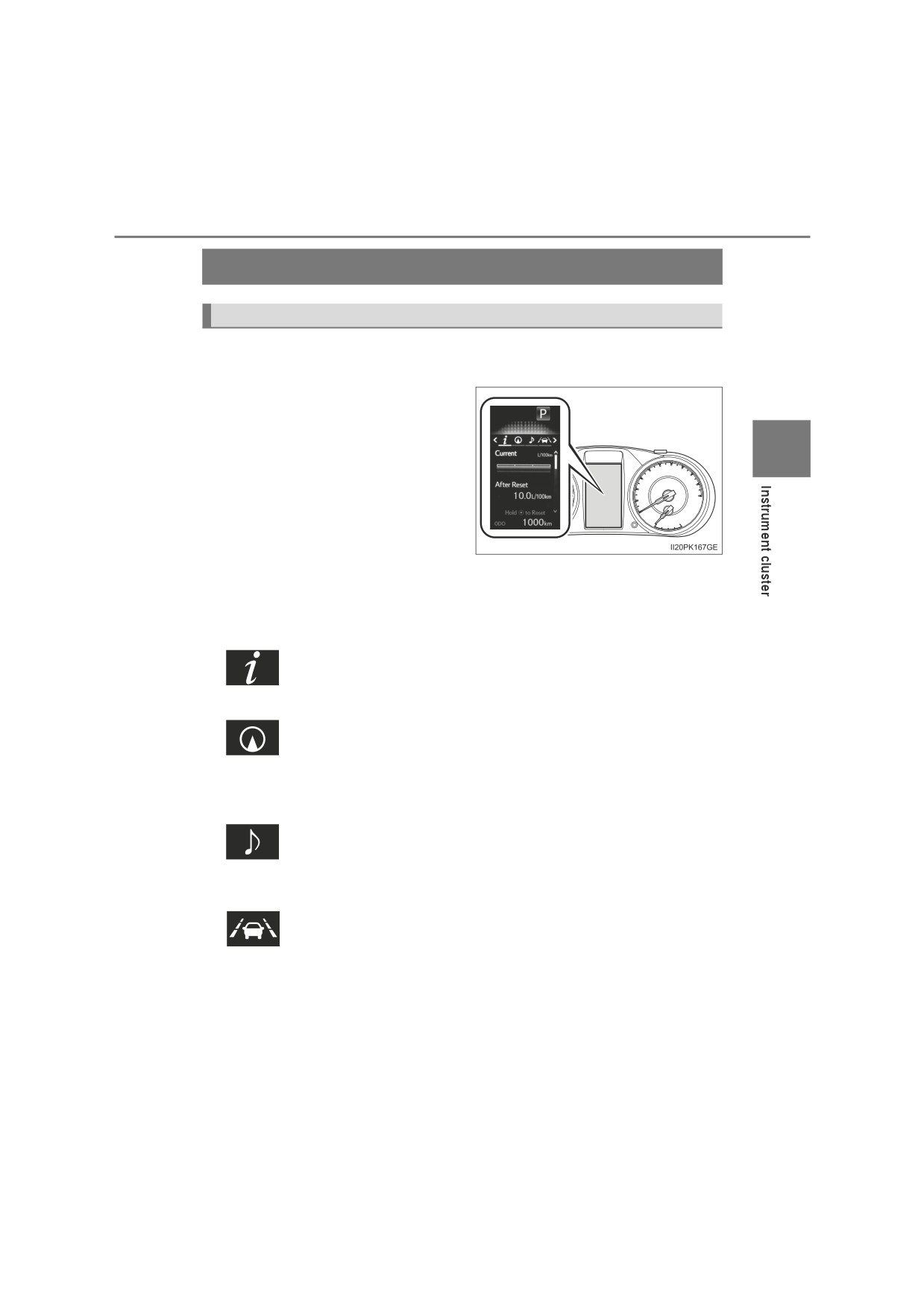
The multi-information display presents the driver with a variety of vehi-
cle data.
The following information will be
displayed when a menu icon is
selected.
2
Menu icons are displayed for a
few seconds when the meter con-
trol switches (P. 134) are oper-
ated.
On the area, normally the outside
temperature is displayed.
(P. 128)
Some of the information may be displayed automatically depending
on the situation.
Drive information
Select to display various drive data. (P. 135)
Navigation system-linked display (if equipped)
Select to display the following navigation system-linked information.
• Route guidance
• Compass display
Audio system-linked display (if equipped)
Select to enable selection of an audio source or track on the meter
using the meter control switches.
Driving support system information (if equipped)
Select to display the operational status of the following systems:
• LDA (Lane Departure Alert With Yaw Assist Function) (P. 282)
• RSA (Road Sign Assist) (P. 293)
• Dynamic radar cruise control (P. 299)
: If equipped
134
2. Instrument cluster
Warning message display
Select to display warning messages and measures to be taken if a
malfunction is detected. (P. 573)
Settings display
Select to change the meter display settings. (P. 645)
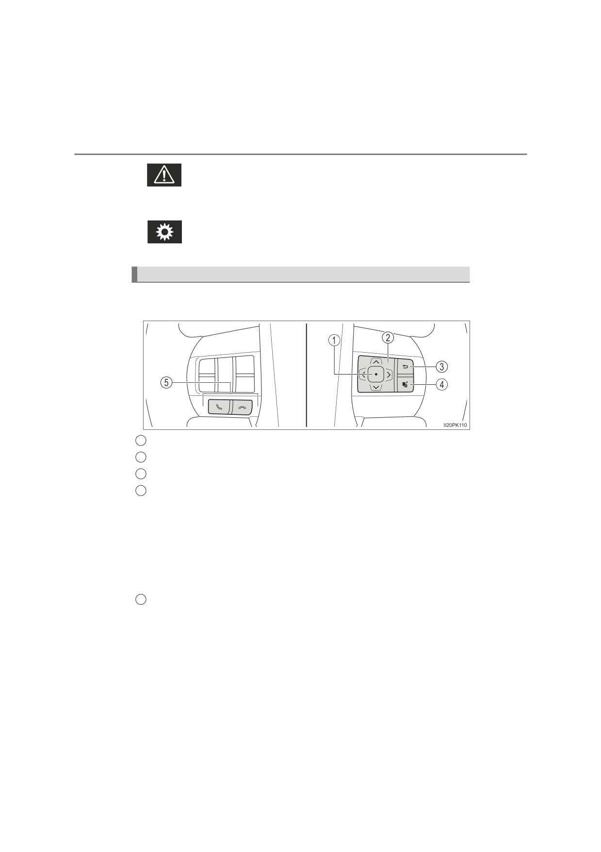
Operating the meter control switches
The multi-information display is operated using the meter control
switches.
1
Enter/Set
2
Select an item/Change pages
3
Return to the previous screen
4
Press: Displays the screen registered as the top screen
When no screen has been registered, the drive information screen will be
displayed.
Press and hold: Registers the currently displayed screen as the top
screen
When the confirmation screen is displayed, select yes to register the
screen. If the selected screen cannot be registered, a registration failure
message will be shown.
Incoming call display (if equipped)
5
Linked with the hands-free system, incoming call is displayed. For details
regarding the hands-free system, refer to “Navigation and multimedia sys-
tem Owner’s manual” or “Multimedia Owner’s Manual”.
2. Instrument cluster
135
Drive information
Items displayed can be switched by pressing “<” or “>” of the meter
control switches to select
and pressing “” or “”.
■ Drive information 1 and 2
● Current fuel economy (bar type/value type)*1, 2
Displays the current rate of fuel consumption.
● Average fuel economy (after reset*3/after start/after refuel)*1, 2
Displays the average fuel consumption since the function was
2
reset, the engine was started and the vehicle was refueled
respectively.
● Average speed (after reset*3/after start)*1
Displays the average vehicle speed since function was reset and
the engine was started respectively.
● Elapsed time (after reset*3/after start)*1
Displays the elapsed time since the function was reset and the
engine was started respectively.
● Distance (range/after start)*1
Displays the estimated maximum distance that can be driven
with the quantity of fuel remaining and the distance driven after
the engine was started respectively.
• This distance is computed based on your average fuel con-
sumption. As a result, the actual distance that can be driven
may differ from that displayed.
• When only a small amount of fuel is added to the tank, the dis-
play may not be updated.
When refueling, turn the engine switch off. If the vehicle is
refueled without turning the engine switch off, the display may
not be updated.
1: Can be registered to drive information 1 and 2. (P. 137)
*2: Use the displayed fuel consumption as a reference.
*3: Resetting procedures:
• Select a function to be reset using the meter control switches and
then press and hold
to reset.
• If there is more than one function that can be reset, check boxes will
be displayed next to those functions.
136
2. Instrument cluster
■ Eco Driving Indicator Zone Display/Eco Score
• Displays Zone of Eco driving with current Eco driving ratio based
on acceleration. (P. 126)
• Displays the eco-driving total count to help improve the cus-
tomer’s eco driving techniques. (P. 139)
■ Eco Saving
Displays the fuel consumption comparison, the average fuel con-
sumption after reset, and the cost of the consumed fuel. (P. 140)
■ Steering angle
Displays the direction of the front tires.
The tire direction is displayed in 3 stages for both left and right, in accor-
dance with the angle of the tire.
While Toyota parking assist-sensor (P. 319) is operating (if equipped)
or any door is not fully closed, the related information is displayed with
the direction of the front tires.
If a battery terminal is disconnected and reconnected, the display may
be disabled temporarily. After driving the vehicle for a while, the display
will be enabled.
■ Speedometer display
Displays the vehicle speed.
■ AdBlue™ gauge (if equipped)
Displays the quantity of AdBlue™ remaining in the tank. (P. 141)
2. Instrument cluster
137
Settings display
The settings of the following items can be changed, refer to P. 644
■ LDA (Lane Departure Alert With Yaw Assist Function)
(if
equipped) (P. 282)
Select to set up the following items.
● Yaw Assist
Select to enable/disable yaw assist function.
● Warning Sensitivity
2
Select to set the warning sensitivity.
● Sway Warning Function
Select to enable/disable the vehicle sway warning.
● Sway Warning Sensitivity
Select to set the vehicle sway warning sensitivity.
■ PCS (Pre-Collision System) (if equipped) (P. 271)
Select to set up the following items.
● PCS On/Off
Select to enable/disable the pre-collision system.
● Sensitivity (adjust alert timing)
Select to change the pre-collision warning timing.
■ RSA (Road Sign Assist) (if equipped) (P. 293)
Select to set up the following items.
● Road Sign Assist On/Off
Select to enable/disable the RSA system.
● Notification Method (excess speed/No overtaking/others*)
Select to change each notification method used to warn
the
driver when the system recognizes excess speed, no overtaking
and no-entry sign.
*: No-entry notification only. (vehicles with navigation system)
● Notification Level
Select to change each notification level used to warn the driver
when the system recognizes a speed limit sign.
138
2. Instrument cluster
■ DRCC(RSA) (if equipped) (P. 310)
Select to enable/disable the Dynamic Radar Cruise Control with
Road Sign Assist.
■ Vehicle Setting
Idling stop (if equipped)
Select to change the idling stop time (engine stop time via the
Stop & Start system) when the air conditioning system is on.
■ Meter Customization
● Language
Select to change the language on the display.
● Units
Select to change the unit for measure of the fuel consumption.
● Eco Driving Indicator Light
Select to activate/deactivate the Eco Driving Indicator Light.
(P. 126)
● switch settings
You can register 1 screen as the top screen. To register, press
and hold
while the desired screen is displayed.
● Drive information 1 and 2
Select to select up to 2 items that will be displayed on a drive
information screen, up to 2 drive information screens can be set.
● Pop-up display (if equipped)
Select to set the pop-up displays, which may appear in some sit-
uations, on/off.
● Accent color (if equipped)
Select to change the accent colors on the screen, such as the
cursor color.
2. Instrument cluster
139
● Eco Saving
Select to set or change the fuel consumption comparison and
fuel price.
● Initialization
Registered or changed meter settings will be deleted or returned
to their default setting.
■Pop-up display
The pop-up display is displayed on the multi-information display according to
2
the operating conditions of the following functions:
● Route guidance display of the navigation system-linked system (if equipped)
●Incoming call display of the hands-free phone system (if equipped)
● Stop & Start system operation time (if equipped)
● Stop & Start system operation status (if equipped)
The pop-up display function can be set on/off. (P. 645)
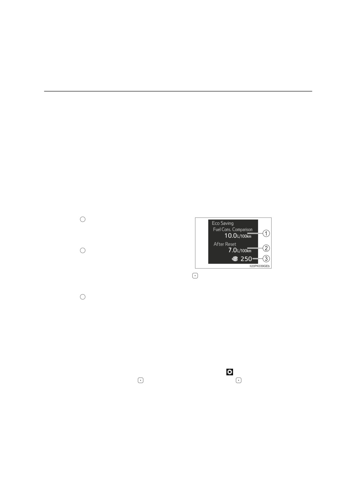
■Eco Score
Driving conditions are displayed in 5 stages and divided into 3 categories:
start, cruise and stop. Every time the vehicle is stopped, the score is dis-
played. (Every time the vehicle is accelerated the score that was last dis-
played is reset. Accumulative scores are not calculated.)
1
Eco Score
Totals the counts of the eco start, eco
cruise and eco stop, and displays the
result.
2
Eco start
Displays the eco level calculated from
degree of acceleration when starting
the vehicle
3
Eco cruise
Displays the eco level calculated from acceleration operation amount when
driving the vehicle
4
Eco stop
Displays the eco level calculated from time between releasing the accelera-
tor pedal and vehicle stop
140
2. Instrument cluster
If the accelerator pedal is not depressed, such as when the vehicle is driven
using cruise control
(if equipped) or dynamic radar cruise control
(if
equipped), the driven distance is not included in the Eco Score.
The Eco Score evaluation differs depending on the driving conditions and
environmental factors. The Eco Score may not be linked to fuel consumption.
The Eco Score will not operate in the following conditions:
● The vehicle speed is approximately 130 km/h (80 mph) or higher.
● The shift lever is in a position other than D. (vehicles with automatic trans-
mission)
● A paddle shift switch is operated. (vehicles with paddle shift switches)
● Front-wheel drive control switch is in L4. (if equipped)
●Downhill assist control system is operating. (if equipped)
● The vehicle is in the power mode. (if equipped)
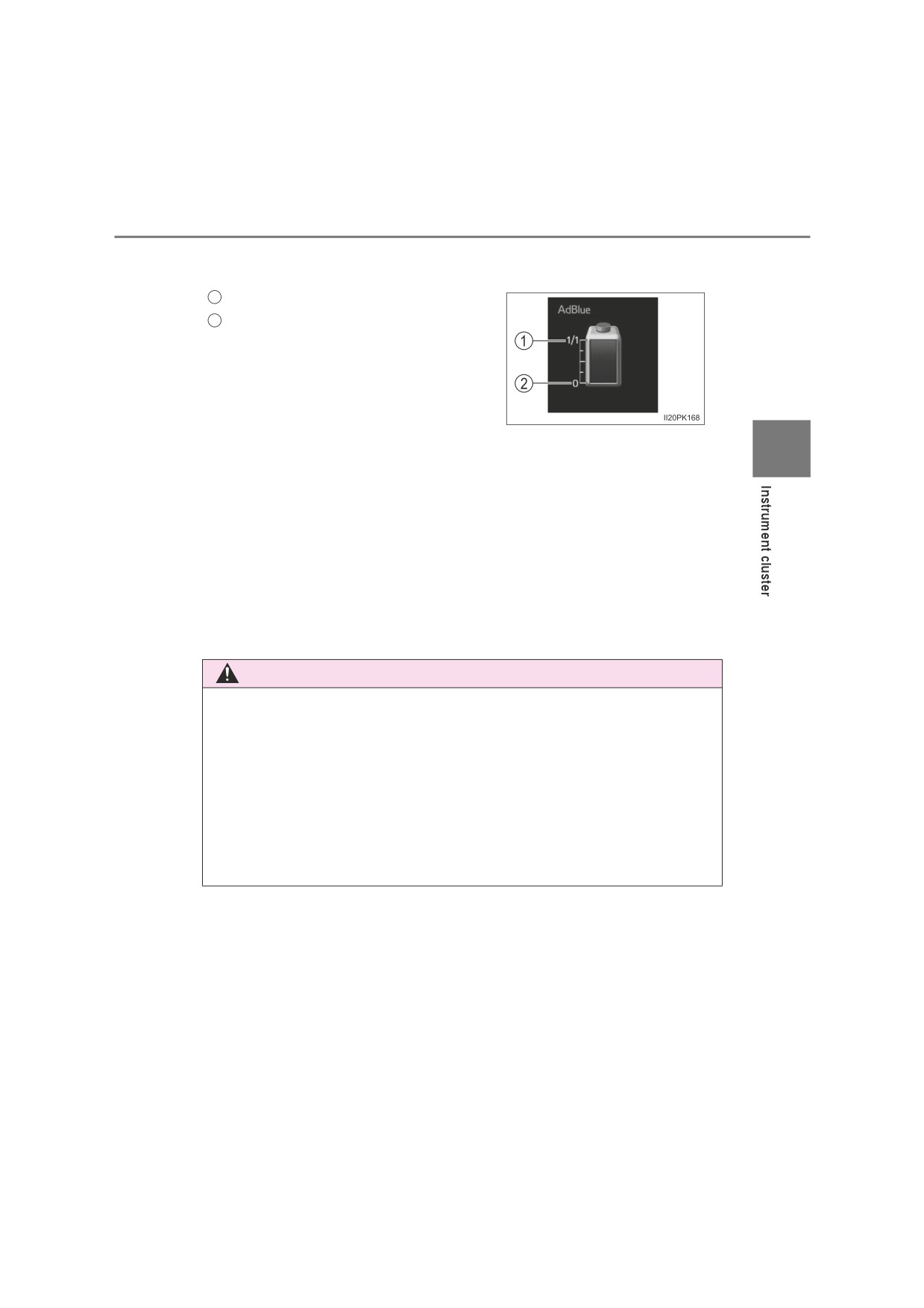
■Eco Saving
Displays the fuel consumption comparison, the average fuel consumption
after reset, and the cost of the consumed fuel.
Fuel consumption comparison
1
Displays the set fuel consumption that
is compared with the actual fuel con-
sumption.
Average fuel consumption after reset
2
Displays the average fuel consumption
since the function was reset.
• The function can be reset by pressing
more than 1 second when the
average fuel consumption after reset is displayed
• Use the average fuel consumption as a reference
3
Savings/fuel cost
Displays the possible savings if the fuel consumption comparison is set,
and displays the actual fuel cost if the fuel consumption comparison is not
set.
Use the displayed fuel cost and savings as a reference. Depending on refuel-
ing methods, driving conditions and environmental factors, the displayed fuel
cost may differ from the actual fuel cost, and in some cases, the fuel cost and
savings may not be linked to the Eco Score evaluation.
■Eco Saving setting
The fuel price and fuel consumption comparison settings can be set in the
settings display. Use the meter control switches to select
while the vehicle
is stopped and press
, and select “Eco Saving” and press
2. Instrument cluster
141
■ AdBlue™ gauge (if equipped)
Displays the quantity of AdBlue™ remaining in the tank.
1
Full
2
Empty
■ Setting display automatic cancelation
2
In the following situations, setting display in which the settings can be
changed through the meter control switches will automatically be turned off.
●If a warning message appears while the setting display is displayed
● When the vehicle begins to move while the setting display is displayed
■ When disconnecting and reconnecting battery terminals
The drive information data and settings will be reset.
■ Liquid crystal display
Small spots or light spots may appear on the display. This phenomenon is
characteristic of liquid crystal displays, and there is no problem continuing to
use the display.
WARNING
■ Caution for use while driving
● When operating the multi-information display while driving, pay extra
attention to the safety of the area around the vehicle.
●Do not look continuously at the multi-information display while driving as
you may fail to see pedestrians, objects on the road, etc. ahead of the
vehicle.
■ Eco Score
Use the Eco Score as a reference. Always drive safely in accordance with
road and traffic conditions.
142
2. Instrument cluster
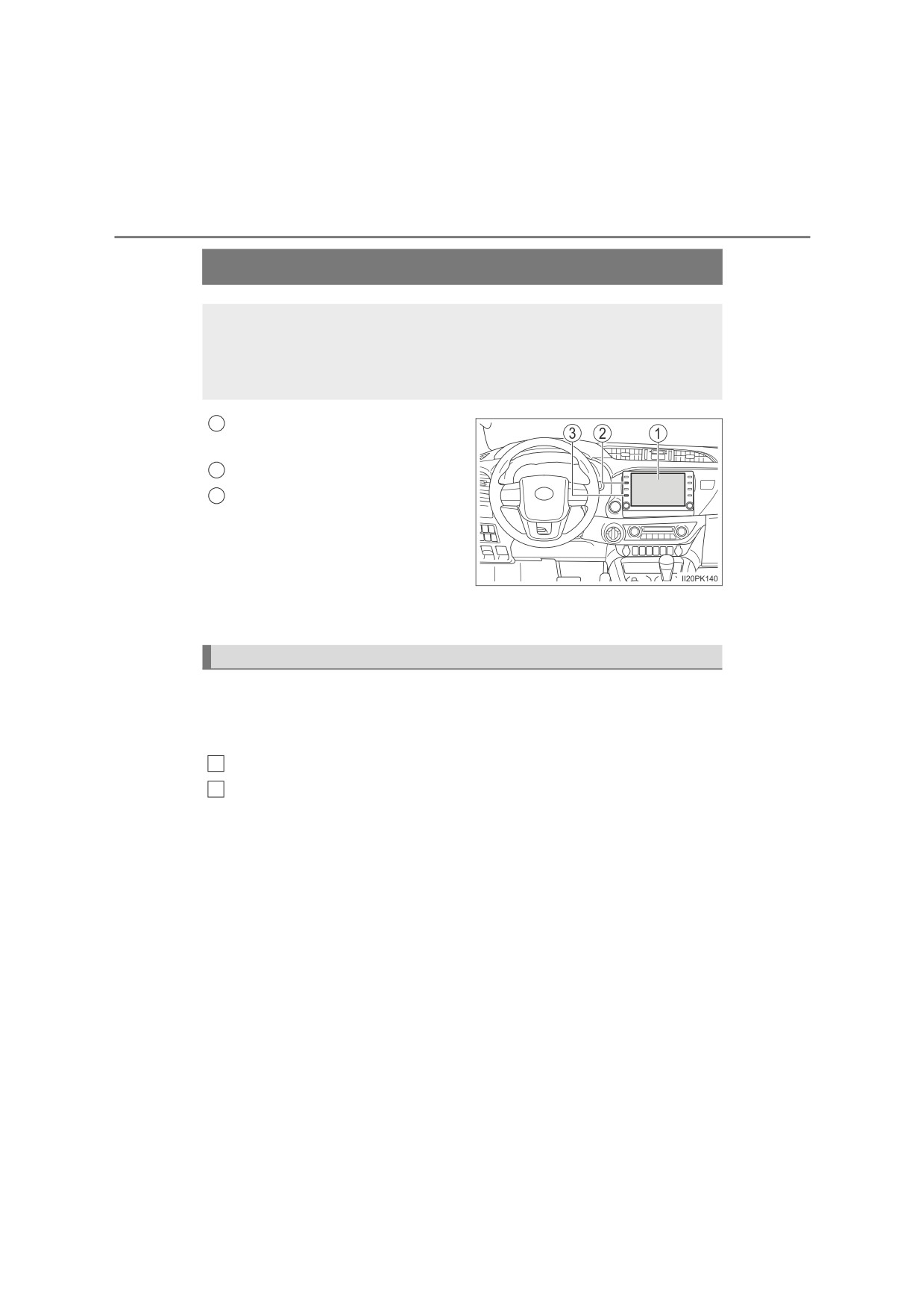
Fuel consumption information
The fuel consumption information can be displayed on the navi-
gation system or multimedia system type A* screen.
*: See “How to identify multimedia system type” to check the type of your
multimedia system. (P. 144)
1
Navigation system or multime-
dia system screen
2
“MENU” button
3
“INFO” button (if equipped)
This illustration is for a left-hand drive vehicle. These button positions
are reversed for right-hand drive vehicles.
Displaying trip information or history screen
When using “INFO” button
Press the “INFO” button.
When using “MENU” button
1
Press the “MENU” button.
2
Select “Info” on the “Menu” screen.
: If equipped
2. Instrument cluster
143
Fuel consumption
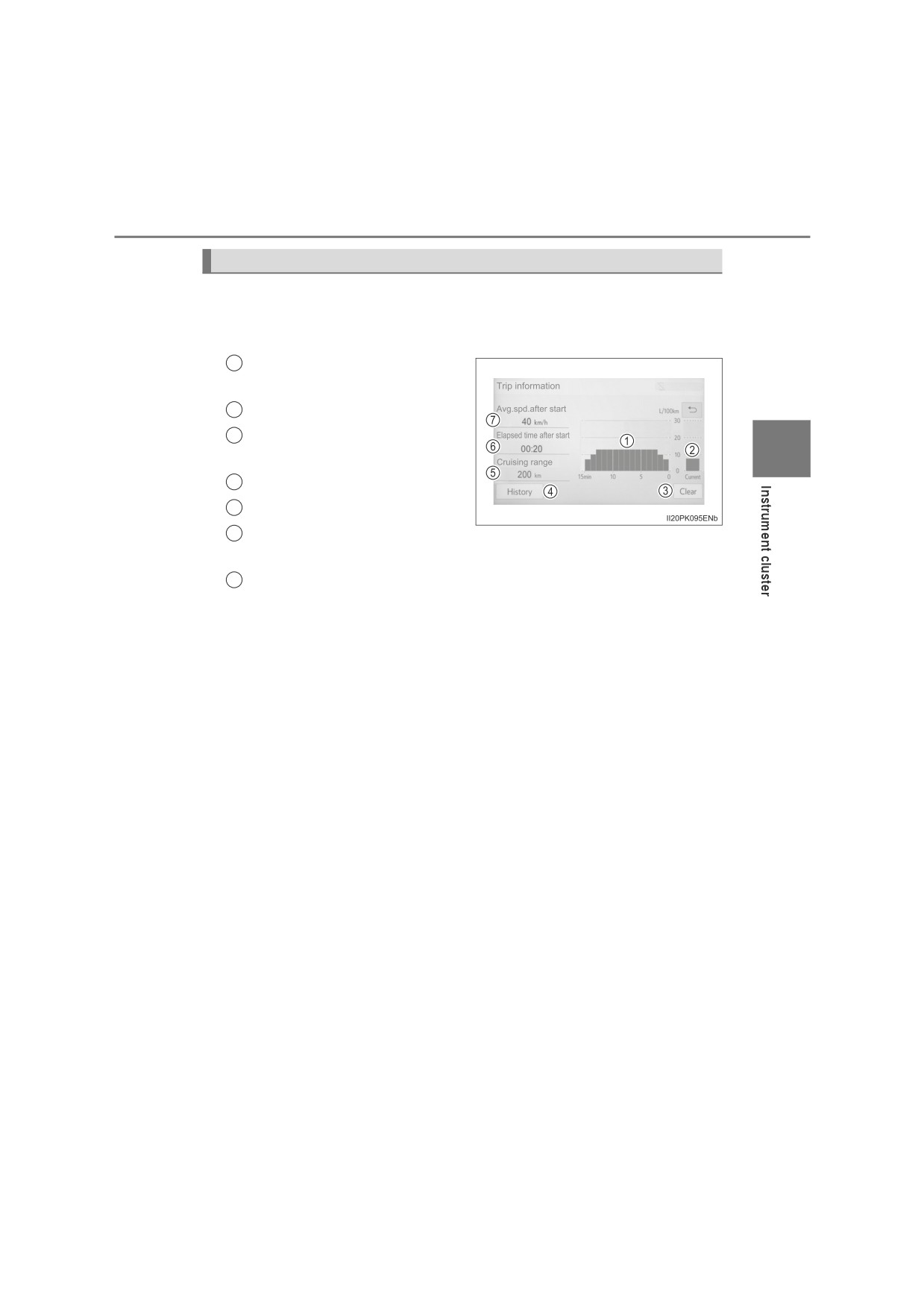
■ Trip information
If the trip information screen does not appear, select “Trip Informa-
tion”.
1
Fuel consumption in the past
15 minutes
2
Current fuel consumption
3
Reset the trip information
2
data
4
“History” screen appears
5
Cruising range
6
Elapsed time since the
engine was started
Average vehicle speed since the engine was started
7
Average fuel consumption for the past 15 minutes is divided by
color into past averages and averages attained since the engine
switch was last turned to the “ON” position (vehicles without smart
entry & start system) or IGNITION ON mode (vehicles with smart
entry & start system). Use the displayed average fuel consumption
as a reference.
These images are examples only, and may vary slightly from actual
conditions.
144
2. Instrument cluster
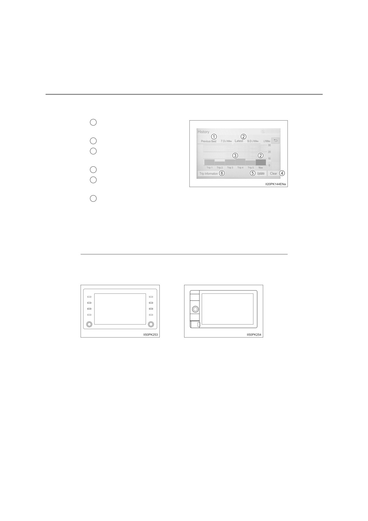
■ History
If the history screen does not appear, select “History”.
1
Best recorded fuel consump-
tion
2
Latest fuel consumption
3
Previous fuel consumption
record
4
Reset the history data
5
Update the latest fuel con-
sumption data
“Trip Information” screen appears
6
The average fuel consumption history is divided by color into past
averages and the average fuel consumption since the last updated.
Use the displayed average fuel consumption as a reference.
These images are examples only, and may vary slightly from actual
conditions.
■ How to identify multimedia system type
Check the type of the multimedia system in the following illustrations.
Type A
Type B
■ Updating the history data
Update the latest fuel consumption by selecting “Update” to measure the cur-
rent fuel consumption again.
■ Resetting the data
The fuel consumption data can be deleted by selecting “Clear”.
■ Cruising range
Displays the estimated maximum distance that can be driven with the quan-
tity of fuel remaining.
This distance is computed based on your average fuel consumption. As a
result, the actual distance that can be driven may differ from that displayed.
145
Operation of
3
each component
3-1.
Key information
Keys
146
3-2.
Opening, closing and
locking the doors
Side doors
151
Access panels (smart-cab
models only)
157
Tailgate
158
Smart entry & start
system
161
3-3.
Adjusting the seats
Front seats
168
Rear seats
170
Head restraints
173
3-4.
Adjusting the steering
wheel and mirrors
Steering wheel
176
Inside rear view mirror
178
Outside rear view
mirrors
180
3-5.
Opening and closing
the windows
Power windows
183
Quarter windows
(smart-cab models)
187
146
3-1. Key information
Keys
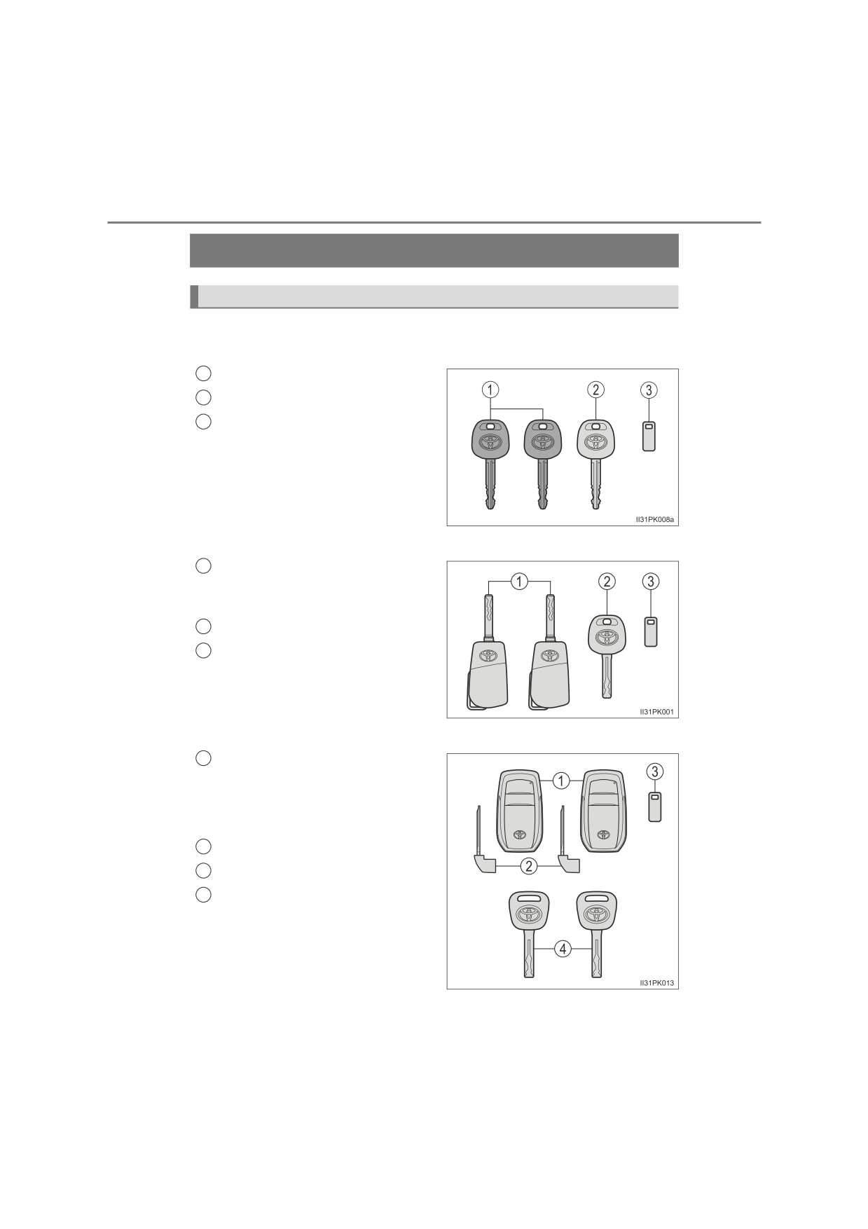
The keys
The following keys are provided with the vehicle.
Type A
1
Master keys
2
Valet key
3
Key number plate
Type B
1
Master keys
Operating the wireless remote con-
trol function (P. 147)
2
Valet key
3
Key number plate
Type C (vehicles with smart entry & start system)
1
Electronic keys
• Operating the smart entry & start
system (P. 161)
• Operating the wireless remote
control function (P. 147)
2
Mechanical keys
3
Key number plate
4
Mechanical keys
(supplemen-
tary keys)
Locking and unlocking the tailgate
(P. 158)
3-1. Key information
147
Wireless remote control (if equipped)
Vehicles without smart entry & start system
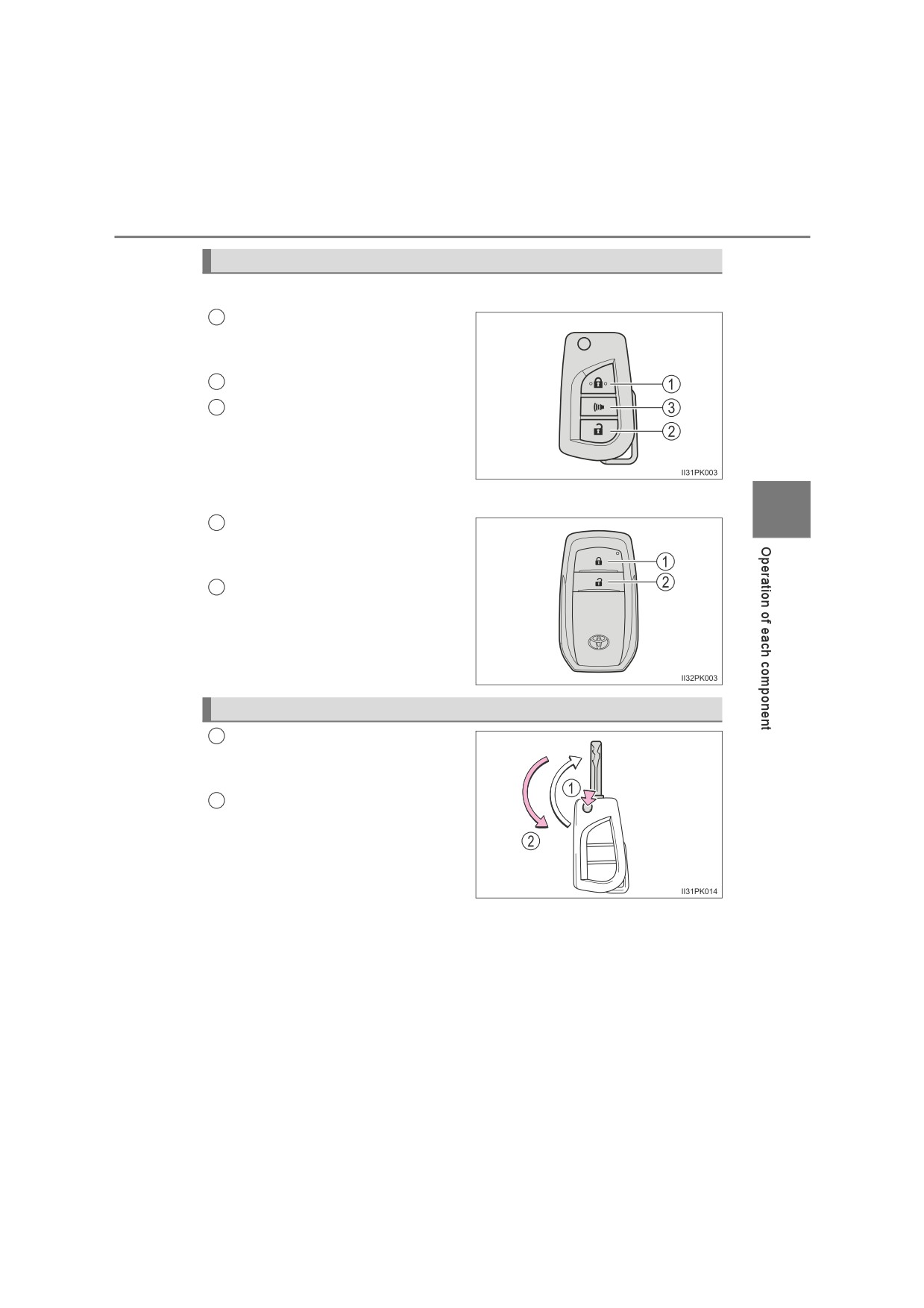
1
Locks all the doors (P. 151)
Check that the door is securely
locked.
2
Unlocks all the doors (P. 151)
3
Sounds the alarm* (P. 148)
*: If equipped
Vehicles with smart entry & start system
3
Locks all the doors (P. 151)
1
Check that the door is securely
locked.
Unlocks all the doors (P. 151)
2
Using the master key (type B)
1
Releasing
To release the key, press the but-
ton.
2
Folding
To stow the key back in its case,
push the key back to the stowed
position while pressing the button.
148
3-1. Key information
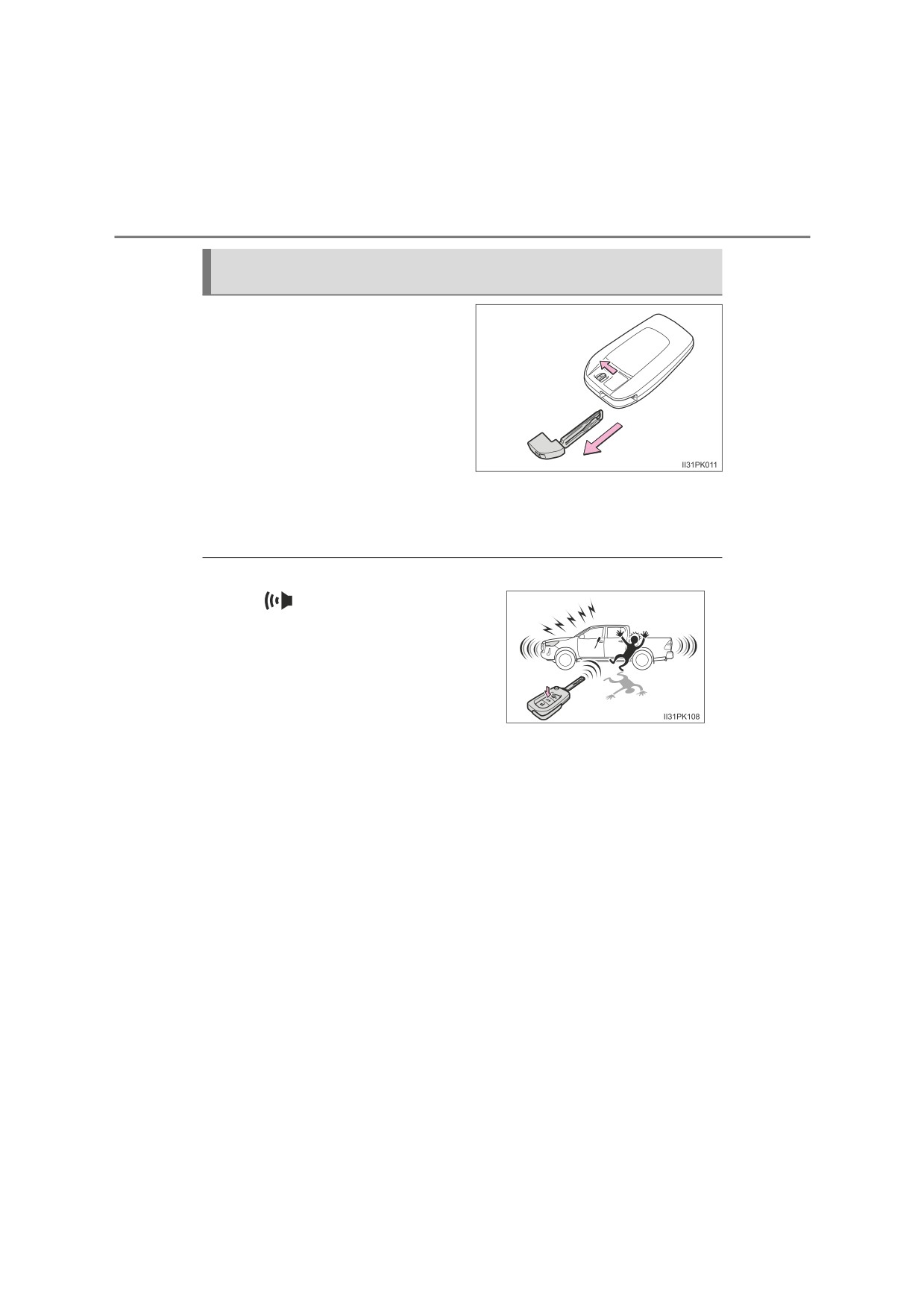
Using the mechanical key (vehicles with smart entry & start sys-
tem)
To take out the mechanical key,
slide the release lever and take
the key out.
The mechanical key can only be
inserted in one direction, as the
key only has grooves on one side.
If the key cannot be inserted in a
lock cylinder, turn it over and re-
attempt to insert it.
After using the mechanical key, store it in the electronic key. Carry the
mechanical key together with the electronic key. If the electronic key bat-
tery is depleted or the entry function does not operate properly, you will
need the mechanical key. (P. 598)
■Panic mode (if equipped)
When
is pressed for longer than
about one second, an alarm will sound
intermittently and the vehicle lights will
flash to deter any person from trying to
break into or damage your vehicle.
To stop the alarm, press any button on the
wireless remote control.
■ When required to leave the vehicle’s key with a parking attendant
Lock the glove box as circumstances demand. (P. 455)
Vehicles without smart entry & start system
Carry the master key for your own use and provide the attendant with the
valet key.
Vehicles with smart entry & start system
Remove the mechanical key for your own use and provide the attendant with
the electronic key only. If there is the supplementary key, carry the supple-
mentary key for your own use as well as the mechanical key.
3-1. Key information
149
■ If you lose your keys
New genuine keys can be made by any authorized Toyota retailer or Toyota
authorized repairer, or any reliable repairer using a master key (vehicles with-
out smart entry & start system) or the other key of the same type (vehicles
with smart entry & start system), and the key number stamped on your key
number plate. Keep the plate in a safe place such as your wallet, not in the
vehicle.
■ When riding in an aircraft (type B and C)
When bringing a key with wireless remote control function onto an aircraft,
make sure you do not press any buttons on the key while inside the aircraft
cabin. If you are carrying the key in your bag etc., ensure that the buttons are
not likely to be pressed accidentally. Pressing a button may cause the key to
emit radio waves that could interfere with the operation of the aircraft.
■ Key battery depletion
3
Vehicles without smart entry & start system
If the wireless remote control function does not operate, the battery may be
depleted. Replace the battery when necessary. (P. 514)
Vehicles with smart entry & start system
P. 166
■ If a message regarding the state of the electronic key or engine switch
mode, etc. is shown
To prevent trapping the electronic key inside the vehicle, leaving the vehicle
without turning off the engine switch or other passengers from unintentionally
taking the key out of the vehicle, etc., a message that prompts the user to
confirm the state of the electronic key or engine switch mode may be shown
on the multi-information display. In those cases, follow the instructions on the
display immediately.
■ If “Key battery low” is shown on the multi-information display
The electronic key has a low battery. Replace the electronic key battery.
■ Replacing the electronic key battery
P. 514
■ Confirmation of the registered key number
The number of keys already registered to the vehicle can be confirmed. Ask
any authorized Toyota retailer or Toyota authorized repairer, or any reliable
repairer for details.
150
3-1. Key information
NOTICE
■ To prevent key damage
●Do not drop the keys, subject them to strong shocks or bend them.
●Do not expose the keys to high temperatures for long periods of time.
●Do not get the keys wet or wash them in an ultrasonic washer etc.
●Do not attach metallic or magnetic materials to the keys or place the keys
close to such materials.
●Do not disassemble the keys.
●Do not attach a sticker or anything else to the surface of the electronic key.
●Do not place the keys near objects that produce magnetic fields, such as
TVs, audio systems and induction cookers, or medical electrical equip-
ment, such as low-frequency therapy equipment.
■ Carrying the electronic key on your person (vehicles with smart entry
& start system)
Carry the electronic key 10 cm (3.9 in.) or more away from electric appli-
ances that are turned on. Radio waves emitted from electric appliances
within 10 cm (3.9 in.) of the electronic key may interfere with the key, caus-
ing the key to not function properly.
■ In case of a smart entry & start system malfunction or other key-related
problems (vehicles with smart entry & start system)
Take your vehicle with all the electronic keys provided with your vehicle to
any authorized Toyota retailer or Toyota authorized repairer, or any reliable
repairer.
■ When an electronic key is lost (vehicles with smart entry & start sys-
tem)
If the electronic key remains lost, the risk of vehicle theft increases signifi-
cantly. Visit any authorized Toyota retailer or Toyota authorized repairer, or
any reliable repairer immediately with all remaining electronic keys that
were provided with your vehicle.
3-2. Opening, closing and locking the doors
151
Side doors
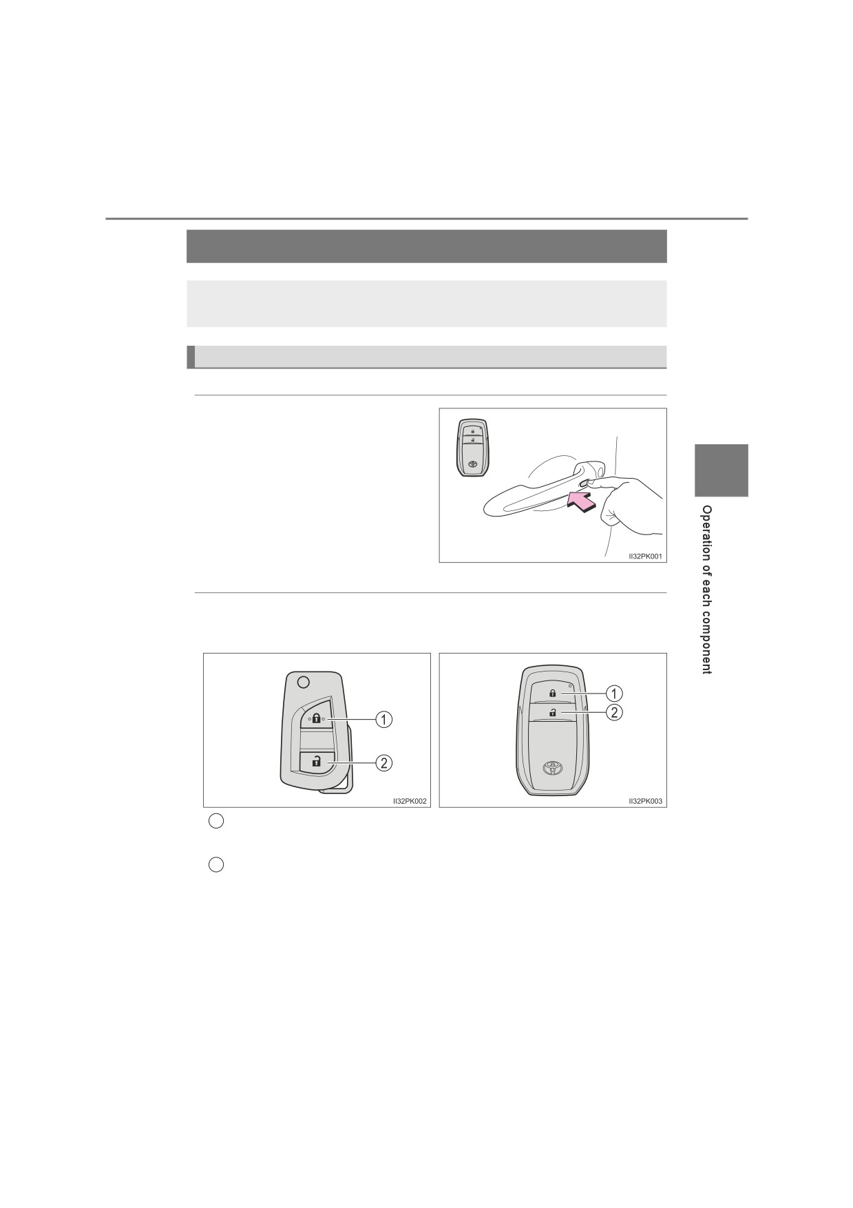
The vehicle can be locked and unlocked using the entry func-
tion, wireless remote control, key or door lock switch.
Locking and unlocking the doors from outside
◆ Smart entry & start system (if equipped)
While carrying the electronic
key, press the button to lock
and unlock.
3
After locking, check that the
door is securely locked.
◆ Wireless remote control (if equipped)
Vehicles without smart entry &
Vehicles with smart entry &
start system
start system
1
Locks all the doors
Check that the door is securely locked.
2
Unlocks all the doors
152
3-2. Opening, closing and locking the doors
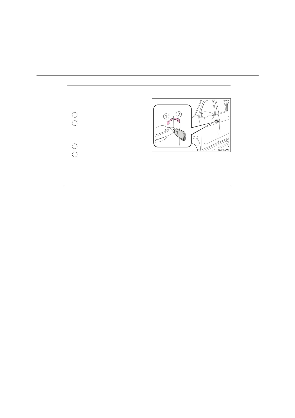
◆ Key
Vehicles without smart entry & start system
Vehicles without power door
lock system:
1
Locks the door
2
Unlocks the door
Vehicles with power door lock
system:
1
Locks all the doors
2
Unlocks all the doors
Vehicles with smart entry & start system
The doors can also be locked and unlocked with the mechanical
key. (P. 598)
■ Operation signals
A buzzer (if equipped) sounds and the emergency flashers flash to indicate
that the doors have been locked/unlocked using the smart entry & start sys-
tem or the wireless remote control. (Locked: once; Unlocked: twice)
■ Security feature
If a door is not opened within approximately 30 seconds after the vehicle is
unlocked using the smart entry & start system or the wireless remote control,
the security feature automatically locks the vehicle again.
■ Door lock buzzer (vehicles with wireless remote control and smart entry
& start system)
If an attempt to lock the doors is made when a door is not fully closed, a
buzzer sounds continuously for 5 seconds. Fully close the door to stop the
buzzer, and lock the vehicle once more.
■ If the entry function (vehicles with smart entry & start system) or the
wireless remote control (if equipped) does not operate properly
● Vehicles without smart entry & start system: Use the key to lock and unlock
the doors. (P. 152)
● Vehicles with smart entry & start system: Use the mechanical key to lock
and unlock the doors. (P. 598)
● Replace the battery with a new one if it is depleted. (P. 514)
3-2. Opening, closing and locking the doors
153
■ Setting the alarm (if equipped)
Locking the doors will set the alarm system. (P. 115)
■ If a symbol indicating one or more doors are open is shown on the multi-
information display
One or more of the doors is not fully closed. The system also indicates which
doors are not fully closed. If the vehicle reaches a speed of 5 km/h (3 mph),
master warning light flashes and a buzzer sounds to indicate that the door(s)
are not yet fully closed.
Make sure that all the doors are closed.
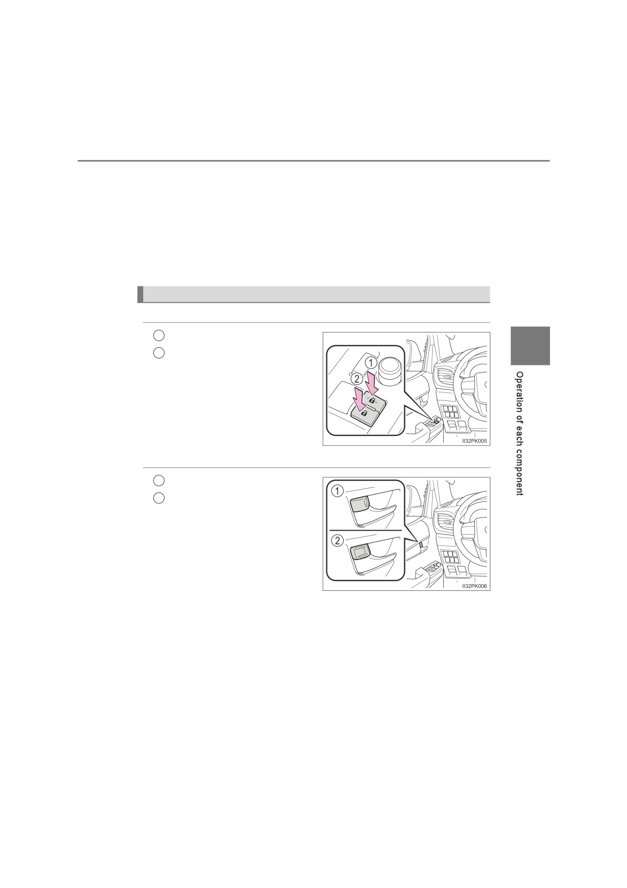
Locking and unlocking the doors from inside
◆ Door lock switch (if equipped)
1
Locks all the doors
3
2
Unlocks all the doors
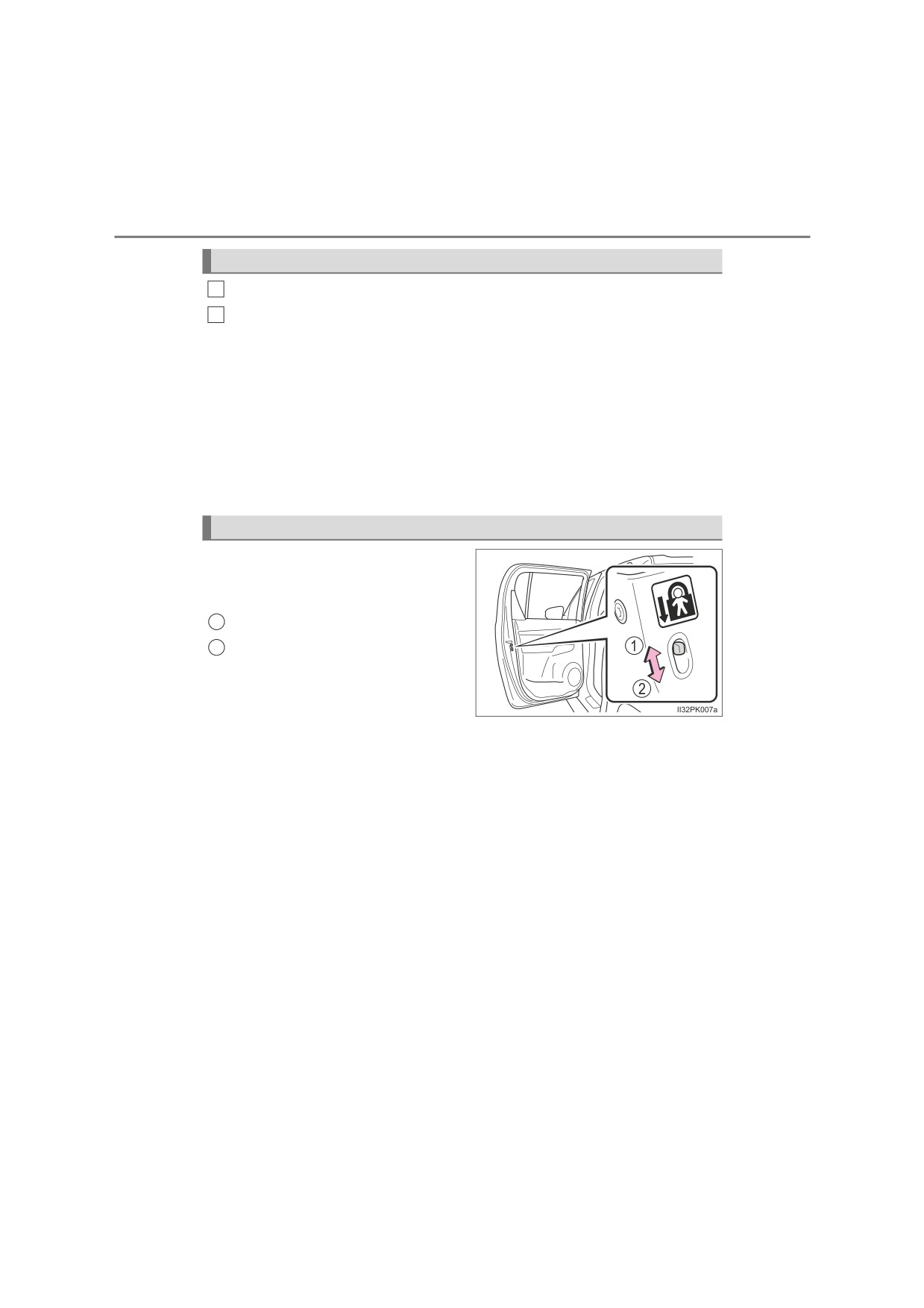
◆ Inside lock button
1
Locks the door
2
Unlocks the door
The driver’s door can be opened
by pulling the inside handle
even if the lock button is in the
lock position.
154
3-2. Opening, closing and locking the doors
Locking the front doors from the outside without a key
1
Move the inside lock button to the lock position.
2
Close the door while pulling the door handle.
Vehicles without smart entry & start system (vehicles with power door
lock system): The driver’s door cannot be locked if either of the door is
open and the key is in the engine switch.
Vehicles with smart entry & start system: The door cannot be locked if
the engine switch is in ACCESSORY or IGNITION ON mode, or the
electronic key is left inside the vehicle.
However, the key may not be detected correctly and the door may be
locked.
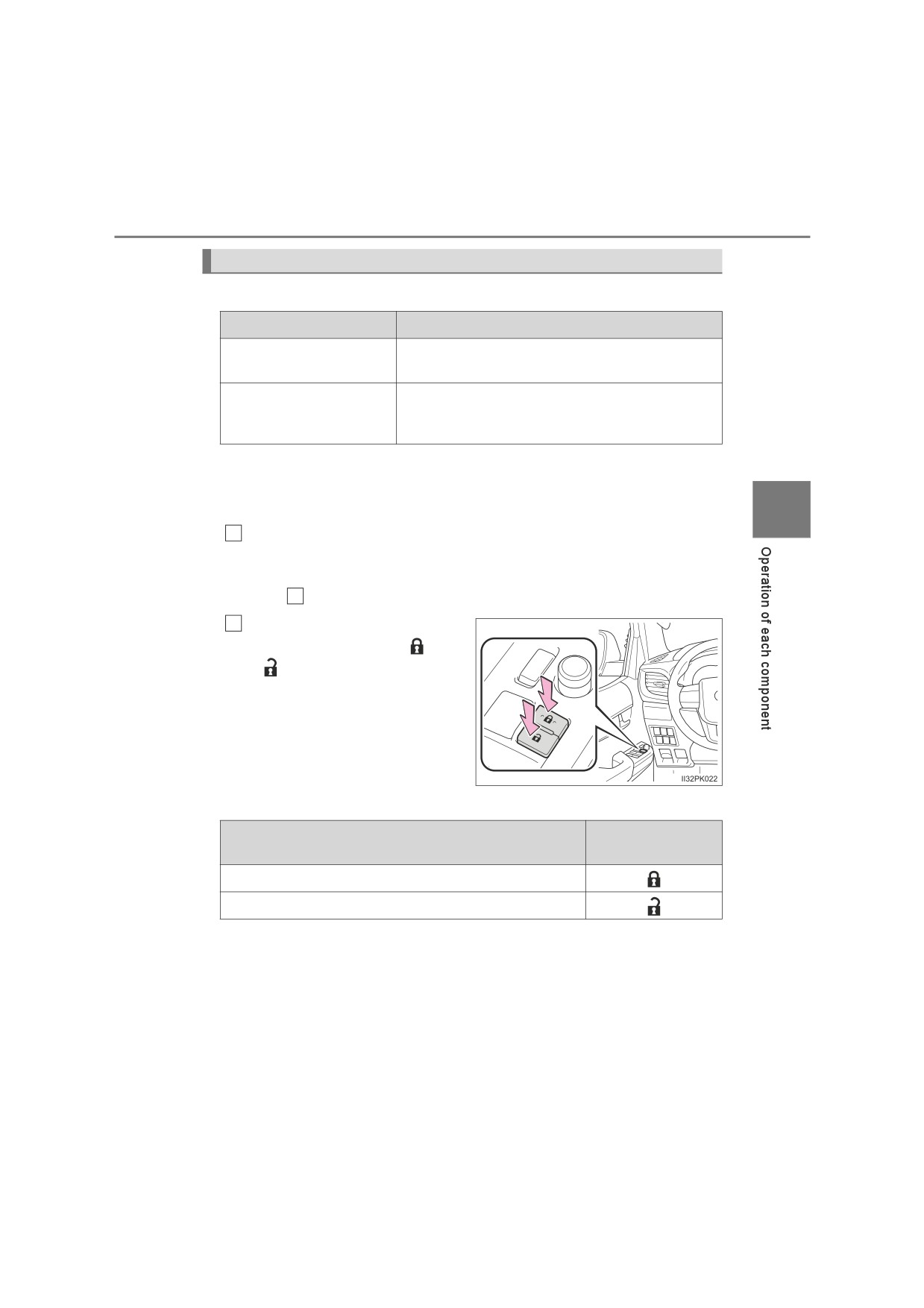
Rear door child-protector lock (double-cab models only)
The door cannot be opened from
inside the vehicle when the lock is
set.
1
Unlock
2
Lock
These locks can be set to prevent
children from opening the rear
doors. Push down on each rear
door switch to lock both rear doors.
3-2. Opening, closing and locking the doors
155
Automatic door locking and unlocking systems (if equipped)
The following functions can be set or canceled:
Function
Operation
Speed linked door lock-
All the doors are locked when the vehicle speed
ing function
is approximately 20 km/h (12 mph) or higher.
All the doors are unlocked when the driver’s
Driver’s door linked door
door is opened within approximately 45 seconds
unlocking function
after turning the engine switch off.
■ Setting and canceling the functions
To switch between setting and canceling, follow the procedure
3
below.
Close all the doors and turn the engine switch to the “ON” posi-
1
tion (vehicles without smart entry & start system) or IGNITION
ON mode (vehicles with smart entry & start system). (Perform
step
2
within 20 seconds.)
2
Press and hold the driver’s
door lock switch
(
or
) for approximately
5
seconds and then release.
The switch positions corre-
sponding to the desired function
to be set are shown in the fol-
lowing table.
Use the same procedure to can-
cel the function.
Driver’s door lock
Function
switch position
Speed linked door locking function
Driver’s door linked door unlocking function
When the setting or canceling operation is complete, all the doors are
locked and then unlocked after the driver’s door lock switch is
released.
156
3-2. Opening, closing and locking the doors
■ Impact detection door lock release system (if equipped)
In the event that the vehicle is subject to a strong impact, all the doors are
unlocked. Depending on the force of the impact or the type of accident, how-
ever, the system may not operate.
■ Conditions affecting operation
Vehicles without smart entry & start system
The wireless remote control function may not operate normally in the follow-
ing situations:
● Near a TV tower, radio station, electric power plant, airport or other facility
that generates strong radio waves
● When carrying a portable radio, cellular phone or other wireless communi-
cation device
● When multiple wireless keys are in the vicinity
● When the wireless key is in contact with, or is covered by a metallic object
● When a wireless key (that emits radio waves) is being used nearby
● When the wireless key has been left near an electrical appliance such as a
personal computer
Vehicles with smart entry & start system
P. 164
WARNING
■ To prevent an accident
Observe the following precautions while driving the vehicle.
Failing to do so may result in a door opening and an occupant falling out,
resulting in death or serious injury.
● Ensure that all doors are properly closed and locked.
●Do not pull the inside handle of the doors while driving.
Be especially careful for the driver’s door, as the door may be opened
even if the inside lock button is in locked position.
● Set the rear door child-protector locks when children are seated in the rear
seats.
3-2. Opening, closing and locking the doors
157
Access panels (smart-cab models only)
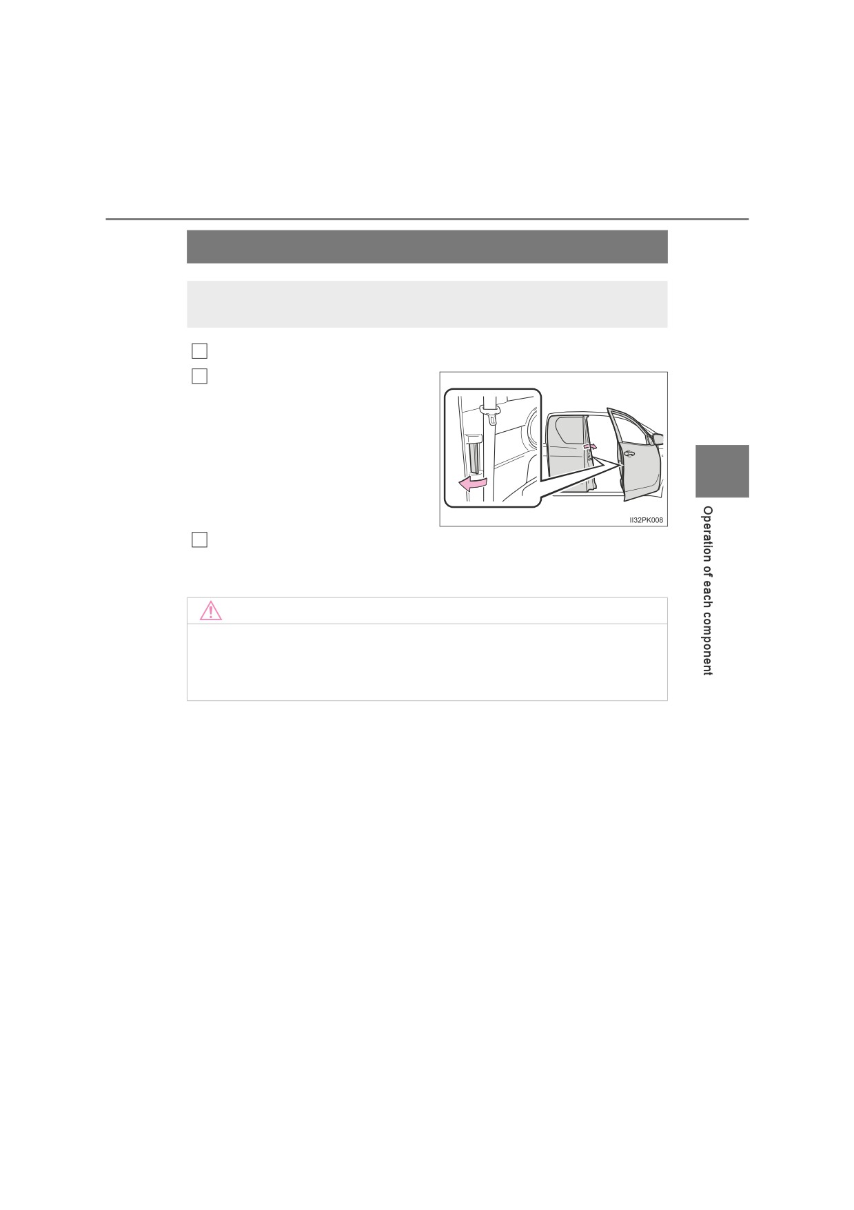
The access panels (rear door) can be opened using the inside
handle.
1
Open the front door widely.
2
Pull (from the outside) or push
(from the inside) the inside han-
dle of the access panels.
3
Open the access panels.
3
You can open and close the access panels only when the front door is
widely opened.
NOTICE
■ When opening or closing the front door and access panels
The front door and access panels could be damaged if they hit each other
when being opened or closed.
158
3-2. Opening, closing and locking the doors
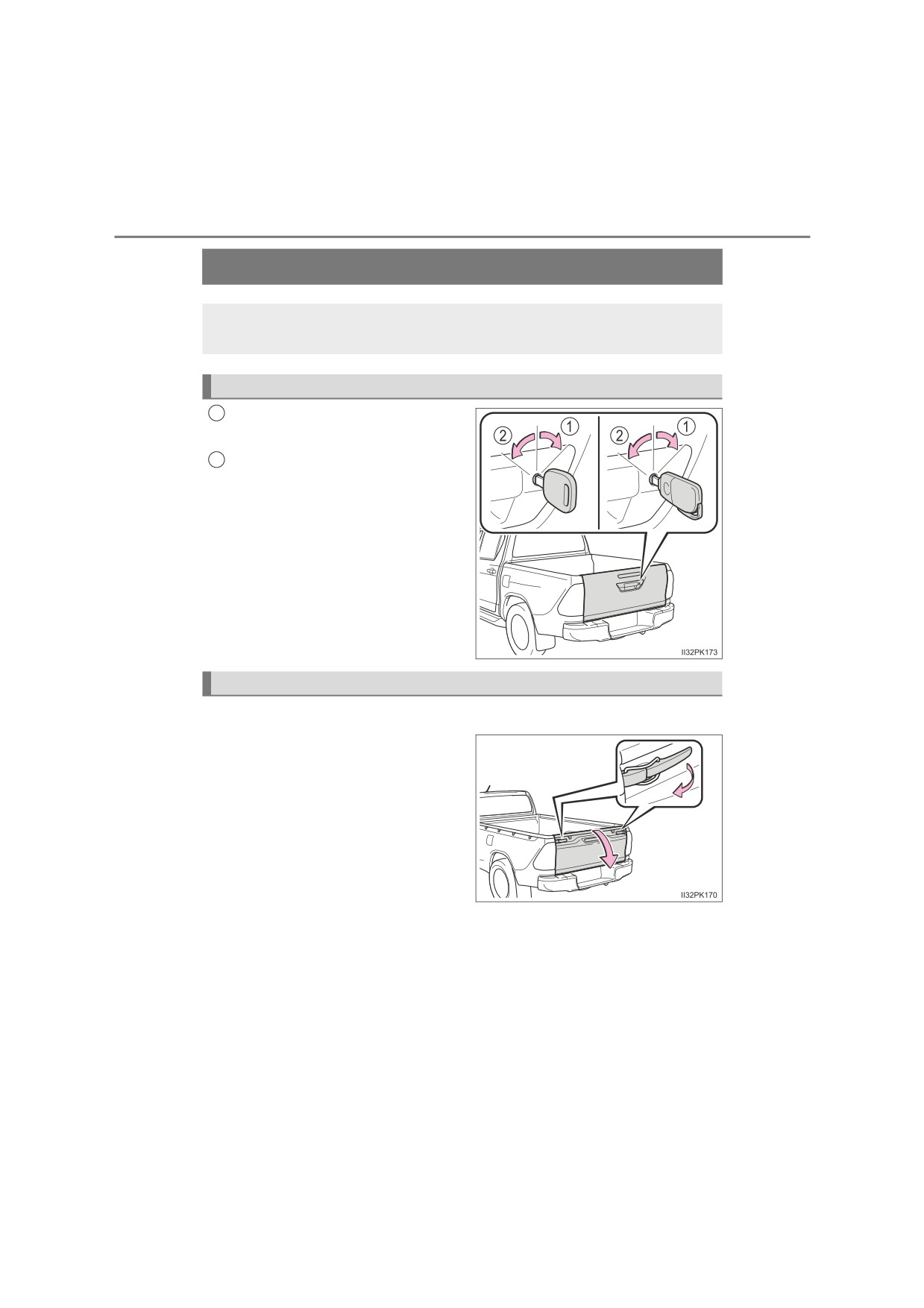
Tailgate
The tailgate can be locked/unlocked and opened by the follow-
ing procedures.
Locking and unlocking the tailgate (vehicles with key hole)
Lock with the master key or the
1
mechanical key
Unlock with the master key or
2
the mechanical key
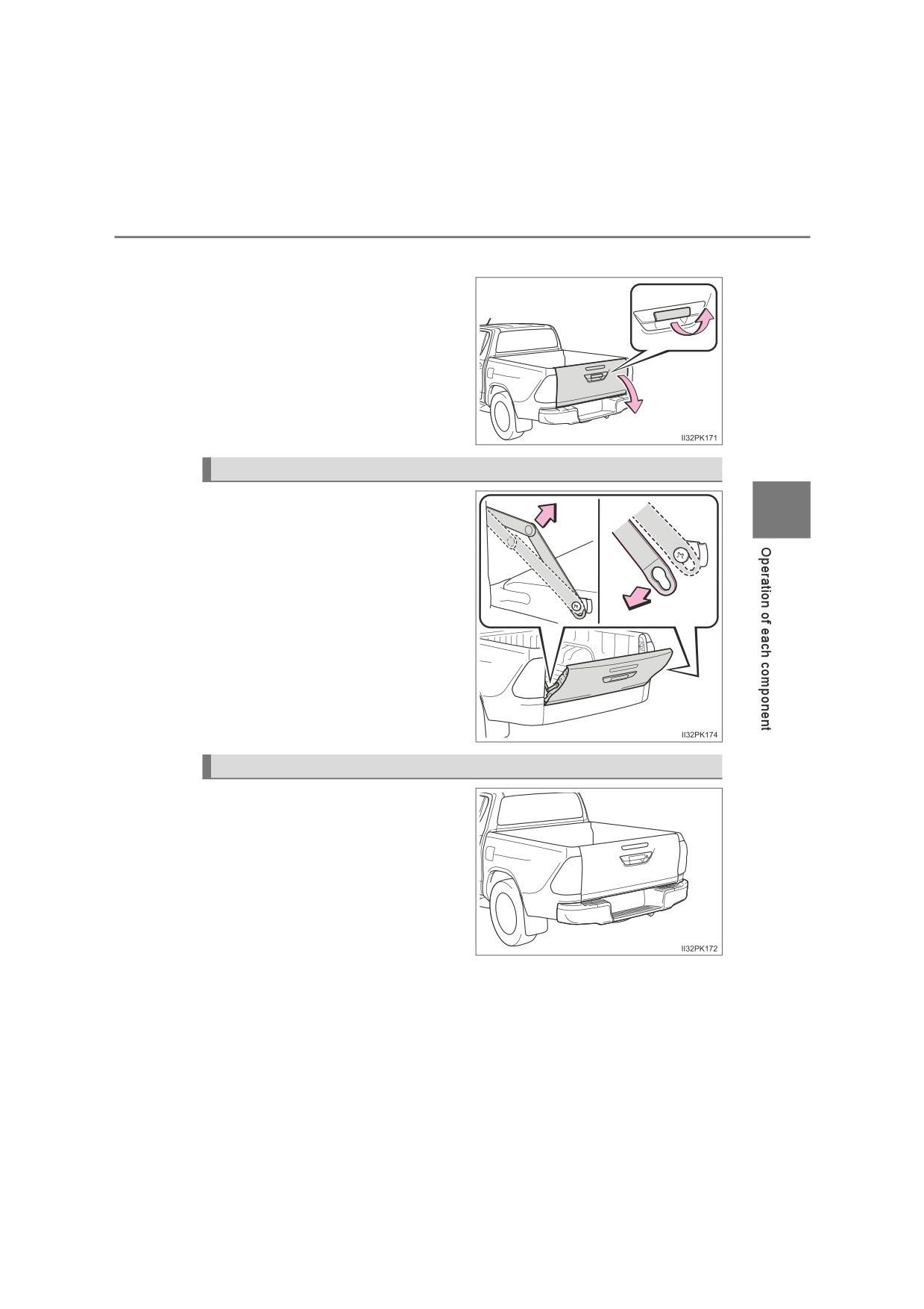
Opening the tailgate
Type A
Unlock the latches and open the
tailgate slowly.
The support stays will hold the tail-
gate horizontal.
After closing the tailgate, try pulling
it toward you to make sure it is
securely locked.
: If equipped
3-2. Opening, closing and locking the doors
159
Type B
Pull the handle and open the tail-
gate slowly.
The support stays will hold the tail-
gate horizontal.
After closing the tailgate, try pulling
it toward you to make sure it is
securely locked.
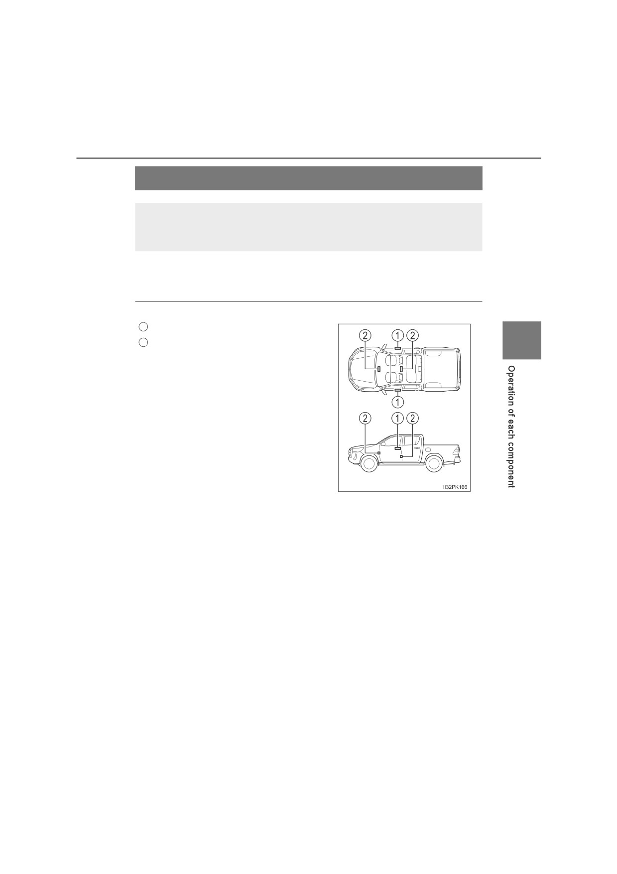
Lowering the tailgate (vehicles without rear bumper)
Release the brackets on the sup-
3
port stays from the lugs on both
sides as shown in the illustration.
Rear step bumper (if equipped)
The rear step bumper is for rear
end protection and easier step-up
loading.
160
3-2. Opening, closing and locking the doors
WARNING
Observe the following precautions.
Failure to do so may result in death or serious injury.
■ Caution while driving
●Do not drive with the tailgate open.
●Do not get on the rear step bumper.
■ When opening or closing the tailgate
●Check the safety of the surrounding area, and be careful not to catch fin-
gers etc. in the tailgate.
●Do not allow a child to open or close the tailgate. Doing so may cause the
child’s hand, head, arm or neck to be caught in the tailgate, resulting in
death or serious injury.
●On an incline, it may be more difficult to open or close the tailgate than on
a level surface.
Also, the tailgate may suddenly open or close. Be careful not to catch fin-
gers etc. in the tailgate.
●When pulling the handle or releasing the support stays, hold and operate
them properly. Failure to do so may cause the hands etc. to be caught,
resulting in serious injury or an unexpected accident.
●Be careful when opening or closing the tailgate in windy weather, as it may
forcefully move.
●After closing the tailgate, make sure it is securely locked.
NOTICE
■ To prevent damage to the rear step bumper
Do not allow more than one person to get on the rear step bumper at a time.
■ Handling of the tailgate (vehicles with rear bumper)
If the support stays are removed, the tailgate comes into contact with the
rear bumper and may be damaged.
3-2. Opening, closing and locking the doors
161
Smart entry & start system
The following operations can be performed simply by carrying
the electronic key on your person, for example in your pocket.
The driver should always carry the electronic key.
● Locks and unlocks the doors (P. 151)
● Starts and stops the engine (P. 221)
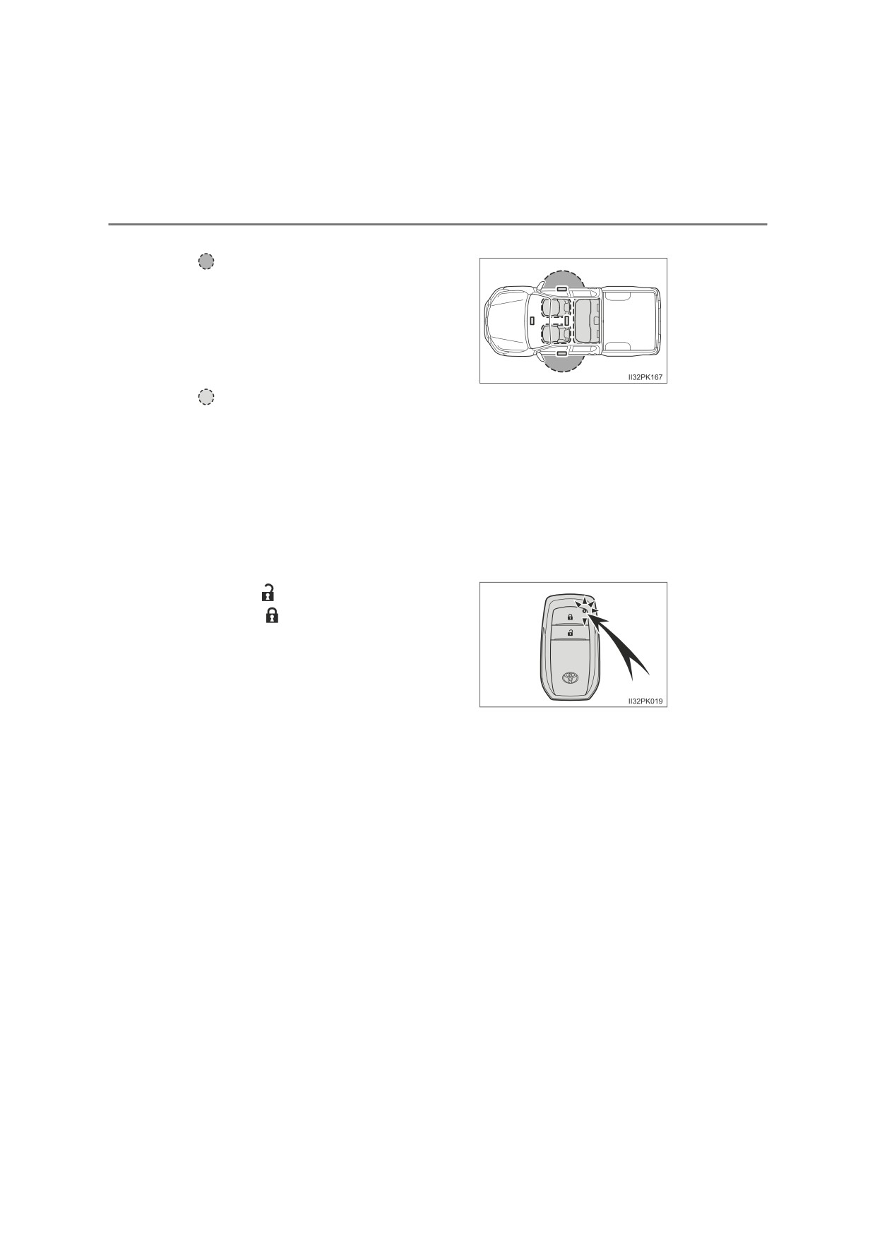
■ Antenna location
1
Antennas outside the cabin
3
2
Antennas inside the cabin
: If equipped
162
3-2. Opening, closing and locking the doors
■ Effective range (areas within which the electronic key is detected)
When locking or unlocking the doors
The system can be operated when the
electronic key is within about 0.7 m (2.3
ft.) of either of the lock/unlock button on
the outside door handle.
(Only the
doors detecting the key can be oper-
ated.)
When starting the engine or changing engine switch modes
The system can be operated when the electronic key is inside the vehicle.
(The electronic key is not detected when it is on the floor or on the instru-
ment panel.)
■ Battery-saving function
The battery-saving function will be activated in order to prevent the battery
from being discharged while the vehicle is not in operation for a long time.
■ Electronic Key Battery-Saving Function
When battery-saving mode is set, battery depletion is minimized by stopping
the electronic key from receiving radio waves.
Press
twice while pressing and
holding
. Confirm that the electronic
key indicator flashes 4 times.
While the battery-saving mode is set, the
smart entry & start system cannot be
used. To cancel the function, press any of
the electronic key buttons.
3-2. Opening, closing and locking the doors
163
■ Alarms and warning indicators
A combination of exterior and interior alarms as well as warning messages
shown on the multi-information display are used to prevent theft of the vehicle
and accidents resulting from erroneous operation. Take appropriate mea-
sures in response to any warning message on the multi-information display.
The following table describes circumstances and correction procedures when
only alarms are sounded.
Alarm
Situation
Correction procedure
Exterior
alarm
An attempt was made to lock
Close all of the doors
sounds once for 5
the vehicle while a door was
and lock the doors
seconds
open.
again.
The engine switch was
turned to ACCESSORY
3
Interior
alarm
mode while the driver’s door
Turn the engine switch
pings
continu-
was open
(or the driver’s
off
and close the
ously
door was opened while the
driver’s door.
engine switch was in
ACCESSORY mode).
164
3-2. Opening, closing and locking the doors
■ Conditions affecting operation
The smart entry & start system uses weak radio waves. In the following situa-
tions, the communication between the electronic key and the vehicle may be
affected, preventing the smart entry & start system, wireless remote control
and engine immobilizer system from operating properly.
(Ways of coping: P. 598)
● When the electronic key battery is depleted
● Near a TV tower, electric power plant, gas station, radio station, large dis-
play, airport or other facility that generates strong radio waves or electrical
noise
● When carrying a portable radio, cellular phone, cordless phone or other
wireless communication device
● When the electronic key is in contact with, or is covered by the following
metallic objects
• Cards to which aluminum foil is attached
• Cigarette boxes that have aluminum foil inside
• Metallic wallets or bags
• Coins
• Hand warmers made of metal
• Media such as CDs and DVDs
● When multiple electronic keys are in the vicinity
● When other wireless keys (that emit radio waves) are being used nearby
● When carrying the electronic key together with the following devices that
emit radio waves
• Another vehicle’s electronic key or a wireless key that emits radio waves
• Personal computers or personal digital assistants (PDAs)
• Digital audio players
• Portable game systems
●If window tint with a metallic content or metallic objects are attached to the
rear window
● When the electronic key is placed near a battery charger or electronic devices
3-2. Opening, closing and locking the doors
165
■ Note for the entry function
●Even if the electronic key is within the effective range (detection areas)
when locking or unlocking the doors, the system may not operate properly if
the electronic key is too close to the window or outside door handle, near
the ground, or in a high place.
● Do not leave the electronic key on top of the instrument panel or near the
door pockets when exiting the vehicle. Depending on the radio wave recep-
tion conditions, it may be detected by the antenna outside the cabin and the
doors will become lockable from the outside, possibly trapping the electronic
key inside the vehicle.
● As long as the electronic key is within the effective range, the doors may be
locked or unlocked by anyone. However, only the doors detecting the elec-
tronic key can be used to unlock the vehicle.
●Even if the electronic key is not inside the vehicle, it may be possible to start
3
the engine if the electronic key is near the window.
●If the wireless remote control is used to lock the doors when the electronic
key is near the vehicle, there is a possibility that the door may not be
unlocked by the entry function. (Use the wireless remote control to unlock
the doors.)
●Pulling the outside door handle while pressing the lock/unlock button on the
outside door handle may prevent the doors from being unlocked. In this
case, return the door handle to the original position, press the lock/unlock
button again, and check that the doors unlock before pulling the door handle
again.
●Unlocking the vehicle may take more time if another electronic key is within
the effective range.
■ When the vehicle is not driven for extended periods
● To prevent theft of the vehicle, do not leave the electronic key within 2 m
(6 ft.) of the vehicle.
● The smart entry & start system can be deactivated in advance. Ask any
authorized Toyota retailer or Toyota authorized repairer, or any reliable
repairer for details.
■ To operate the system properly
Make sure to carry the electronic key when operating the system. Do not get
the electronic key too close to the vehicle when operating the system from the
outside of the vehicle.
Depending on the position and holding condition of the electronic key, the key
may not be detected correctly and the system may not operate properly. (The
alarm may go off accidentally, or the door lock prevention function may not
operate.)
166
3-2. Opening, closing and locking the doors
■ If the smart entry & start system does not operate properly
●Locking and unlocking the doors: Use the mechanical key. (P. 598)
● Starting the engine: P. 599
■ Electronic key battery depletion
● The standard battery life is 1 to 2 years.
● If the battery becomes low, an alarm will sound in the cabin when the engine
stops.
● As the electronic key always receives radio waves, the battery will become
depleted even if the electronic key is not used. The following symptoms indi-
cate that the electronic key battery may be depleted. Replace the battery
when necessary. (P. 514)
• The smart entry & start system or the wireless remote control does not
operate.
• The detection area becomes smaller.
• The LED indicator on the key surface does not turn on.
● To avoid serious deterioration, do not leave the electronic key within 1 m (3
ft.) of the following electrical appliances that produce a magnetic field:
• TVs
• Personal computers
• Cellular phones, cordless phones and battery chargers
• Recharging cellular phones or cordless phones
• Table lamps
• Induction cookers
■ If “Key left inside vehicle” is shown on the multi-information display
An attempt was made to lock the doors using the smart entry & start system
while the electronic key was still inside the vehicle, or an attempt was made
to lock either front door by opening a door and putting the inside lock button
into the lock position, then closing the door by pulling on the outside door
handle with the electronic key still inside the vehicle.
Retrieve the electronic key from the vehicle and lock the doors again.
■ Customization that can be configured at any authorized Toyota retailer
or Toyota authorized repairer, or any reliable repairer
Settings (e.g. smart entry & start system) can be changed.
(Customizable features: P. 644)
■ If the smart entry & start system has been deactivated in a customized
setting
● Locking and unlocking the doors:
Use the wireless remote control or mechanical key. (P. 151, 598)
● Starting the engine and changing engine switch modes: P. 599
● Stopping the engine: P. 223