Chevrolet New Sail (2010). Manual - part 24
 

  Index      Chevrolet     Chevrolet New Sail - service and repair manual 2010 year


Search            copyright infringement  


Content   ..  22  23  24  25   ..


Chevrolet New Sail (2010). Manual - part 24


94 


4. Displacement Pump   
5. Power Accumulator   
6. Intake Valve   
7. Right Rear Brake Caliper   
8. Outlet Valve   
9. Outlet Valve   
10. Left Front Brake Caliper   
11. Intake Valve   


15. Outlet Valve   
16. Outlet Valve   
17. Left Rear Brake Caliper   
18. Non-Return Valve   
19. Intake Valve   
20. Power Accumulator   
21. Displacement Pump   
22. Damper   
23. Orifice   

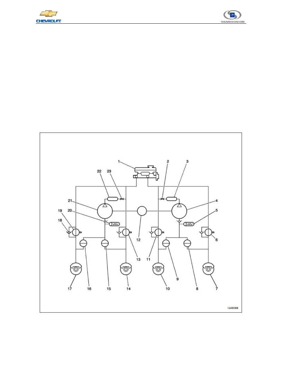
5.3.2  Anti-Lock Braking Mode - Connection   

If, in pressure maintaining or pressure drop mode, the electronic brake control module detects that the wheel 

slip rate has been reduced, then the electronic brake control module will increase the brake fluid pressure of the 
corresponding wheel through applying the Master Cylinder pressure. At this point, the intake valve is open and the 
outlet valve is closed so that the pressure of the normal brake Master Cylinder can be applied to the wheels.     


1. Master Cylinder   
2. Orifice   
3. Damper   

13. Intake Valve   
14. Right Front Brake Caliper   
15. Outlet Valve   


95 

Chevrolet 2010 New Sail New Technical Training 

- Learner's Manual


4. Displacement Pump   
5. Power Accumulator   
6. Intake Valve   
7. Right Rear Brake Caliper   
8. Outlet Valve   
9. Outlet Valve   
10. Left Front Brake Caliper   
11. Intake Valve   
12. Motor   
 

16. Outlet Valve   
17. Left Rear Brake Caliper   
18. Non-Return Valve   
19. Intake Valve   
20. Power Accumulator   
21. Displacement Pump   
22. Damper   
23. Orifice   

5.3.3  Anti-Lock Braking Mode - Maintenance   

When the electronic brake control module detects wheel slip, it will close the intake valve and maintain the 

outlet valve in the brake pressure regulator valve as closed to isolate the system. In this way, the stability of the oil 
pressure in the brakes can be maintained so that there is no oil pressure rise and drop.     


1. Master Cylinder   
2. Orifice   
3. Damper   

13. Intake Valve   
14. Right Front Brake Caliper   
15. Outlet Valve   


96 


4. Displacement Pump   
5. Power Accumulator   
6. Intake Valve   
7. Right Rear Brake Caliper   
8. Outlet Valve   
9. Outlet Valve   
10. Left Front Brake Caliper   
11. Intake Valve   
12. Motor   
 

16. Outlet Valve   
17. Left Rear Brake Caliper   
18. Non-Return Valve   
19. Intake Valve   
20. Power Accumulator   
21. Displacement Pump   
22. Damper   
23. Orifice   

5.3.4  Anti-Lock Braking Mode - Separation   

If the electronic brake control module still detects wheel slip in the pressure maintaining mode, then the 

electronic brake control module will decline the brake fluid pressure of the corresponding wheel. The intake valve 
remains closed and the outlet valve is open. Redundant oil and pressure are temporarily stored in the power 
accumulator inside the brake pressure regulator valve until the oil pump is able to return oil to the fluid storage 
tank of the Master Cylinder.     


1. Master Cylinder   
2. Orifice   
3. Damper   

12. Motor   
13. Intake Valve   
14. Right Front Brake Caliper   


97 

Chevrolet 2010 New Sail New Technical Training 

- Learner's Manual


4. Displacement Pump   
5. Power Accumulator   
6. Intake Valve   
7. Right Rear Brake Caliper   
8. Outlet Valve   
9. Outlet Valve   
10. Left Front Brake Caliper   
11. Intake Valve   


15. Outlet Valve   
16. Outlet Valve   
17. Left Rear Brake Caliper   
18. Non-Return Valve   
19. Intake Valve   
20. Power Accumulator   
21. Displacement Pump   
22. Damper   
23. Orifice   

5.4  Decoupled Dynamic Rear Proportioning 

DDRP   

The DDRP

(decoupled dynamic rear proportioning)system is a proportioning system, which is used for 

maintaining vehicle stability during braking. Under normal braking conditions, the braking force of the rear 
wheels is on the small side because the vehicle’s center of gravity moves forward. DDRP maintains the brake 
pressure required by the rear wheels through the rear intake and outlet valves of the anti-lock braking system

(ABS)to provide effective braking effect and vehicle stability. In the DDRP system, the power of the rear 

maintaining solenoid valve is supplied by the ignition circuit.   

 
If one of the following malfunctions occurs, the red brake warning light will be illuminated.     

z  The two wheel speed sensors on the same axle are out of service.   

z  The rear intake solenoid valve is out of service.   

z  The accumulator 2 and the motor input are short-circuited against the ground.     

z  The accumulator 1 and the electronic brake control module are open-circuited or short-circuited against 

the ground.   

z  The motor ground circuit is open-circuited or short-circuited against the accumulator.     

z  The ground circuit of the electronic brake control module is open-circuited or short-circuited against the 

accumulator.   

z  The ignition circuit is open-circuited or short-circuited against the ground.     


Content   ..  22  23  24  25   ..