Chevrolet New Sail (2010). Manual - part 23


  Index      Chevrolet     Chevrolet New Sail - service and repair manual 2010 year


Search            copyright infringement  


Content   ..  21  22  23  24   ..


Chevrolet New Sail (2010). Manual - part 23


90 


4.7.22  Instrument & Alarm Indicator Light   
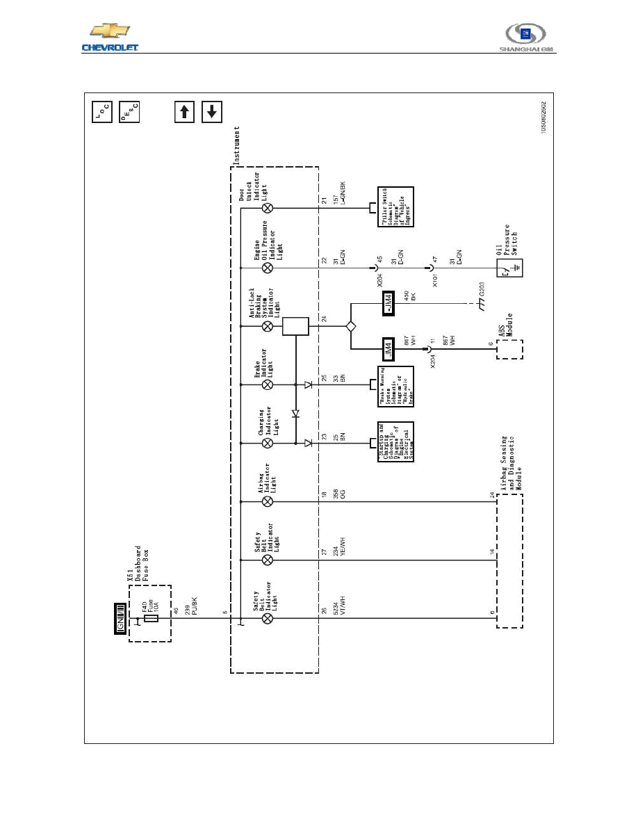


91 

Chevrolet 2010 New Sail New Technical Training 

- Learner's Manual


4.7.23  Instrument Indicator Lights and Illumination   


92 


5  Braking System   

5.1  MGH-25 ABS Oil Circuit Diagram   


1. Fluid Storage Tank   
2. Master Cylinder   
3. Damper   
4. Intake Valve   
5. Outlet Valve   


6. Left Front   
7. Right Rear   
8. Pressure Pump   
9. Energy Storage   
10. Left Rear   
11. Right Front   

5.2  System Introduction   

The MGH-25 anti-lock braking system

(ABS)consists of a normal hydraulic braking system and anti-lock 

components. The normal braking system consists of a vacuum booster, a Master Cylinder, front and rear disc 
brakes, rear drum brakes, hydraulically interconnected brake oil pipe and hose, a brake fluid level sensor, and a 
brake warning light. The anti-lock braking system consists of a hydraulic unit, an electronic brake control module 


93 

Chevrolet 2010 New Sail New Technical Training 

- Learner's Manual


(EBCM), a system fuse, four wheel speed sensors(one for each wheel), interconnecting leads, anti-lock braking 
system indicator lights, a decoupled dynamic rear proportioning 

(DDRP) indicator light (connected with the 

parking brake lamps

), and rear drum brakes. The hydraulic unit and the electronic brake control module 

connected with it are located between the left fluid storage tank and the bulkhead. The configuration of the basic 
hydraulic unit consists of a hydraulic non-return valve, two solenoid valves of each wheel, a hydraulic pump, two 
power accumulators and two dampers. The hydraulic unit controls the front brake calipers and the oil pressure of 
the rear brake wheel cylinders through regulating the oil pressure to prevent wheel lockup.     

5.3  Operation mode   

5.3.1  Normal Braking Mode   

The normal braking mode of the MGH-25 anti-lock braking system 

(ABS)  adopted by this vehicle is a 

diagonally shunted braking system. In this system, an oil circuit of the Master Cylinder supplies pressure to the 
right front and left rear brakes. Another oil circuit supplies pressure to the left front and right rear brakes. All 
valves of the hydraulic regulator are in normal state, i.e. positions with no pressure supplied as shown in the 
hydraulic circuit diagram.     


1. Master Cylinder   
2. Orifice   
3. Damper   

12. Motor   
13. Intake Valve   
14. Right Front Brake Caliper   


Content   ..  21  22  23  24   ..