Chevrolet New Sail (2010). Manual - part 17
 

  Index      Chevrolet     Chevrolet New Sail - service and repair manual 2010 year


Search            copyright infringement  


Content   ..  15  16  17  18   ..


Chevrolet New Sail (2010). Manual - part 17


66 


the door lock system.     


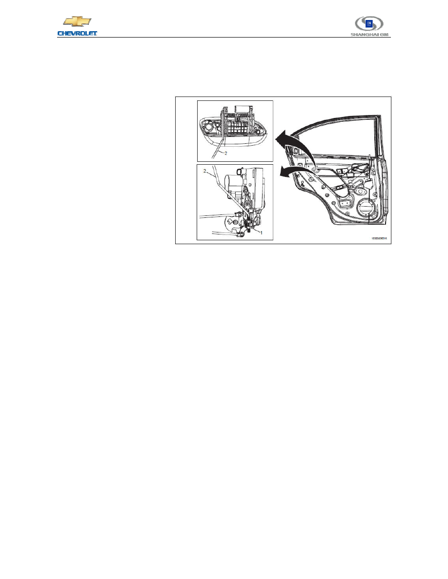
4.3  Adjustment of Outer Rear Door Handle Lever   

1.  Place the outer rear door handle 

lever

(2)in the middle of the 

buckle clamp

(1), and clear up 

any obstruction on the outer 
door handle.     

2.  Move the outer rear door handle 

lever thread in the buckle clamp 
to adjust the handle stroke.     

3.  Close the buckle clamp and 

firmly fix the threaded portion 
of the outer rear door handle 
lever into the buckle clamp.     

4.  Inspect the operation of the 

door lock system.   

4.4  Description and Operation of Data Link Communication   

The configuration of the data link connector

(DLC)is negotiated and set by vehicle manufacturers. The 

connector is necessary when employing a diagnostic instrument to communicate with a vehicle and to program a 
vehicle communication system.     

 
This connector must have the following characteristics:   

z  Able to connect with all trouble diagnostic instruments as a 16-pin connector   

z  Should always supply accumulator power for the trouble diagnostic instrument through its 16th pin.     

z  Should always provide ground point for the trouble diagnostic instrument through its 4th pin.     

z  Should always provide a clean signal ground point through its 5th pin.     


Its rest pins are used to communicate with the serial data of the vehicle system. The module of the vehicle is 

controlled by a microprocessor and carries out intercommunication and communicates with a diagnostic 
instrument through a serial data circuit.     

 
This vehicle employs 2 different types of communication protocols:     

z  Universal Asynchronous Receiver Transmitter 

(UART)   

z  Keyword 2000 Data Circuit   

The diagnostic instrument visits the following module data circuits:     

z  Electronic Brake Control Module 

(EBCM)  (UART)   

z  Engine Control Module 

(ECM)  (Keyword 2000)   


67 

Chevrolet 2010 New Sail New Technical Training 

- Learner's Manual


z  Transmission Control Module 

(TCM)  (UART)   

z  Airbag Sensing and Diagnostic Module 

(SDM)  (UART)   

z  Anti-Theft Locking System Control Module 

(UART)   

z  Anti-Theft Module 

(UART)   

4.4.1  Universal Asynchronous Receiver Transmitter 

UART Data Circuit  

The communication system based on the universal asynchronous receiver transmitter has a main serial data 

circuit and a long-distance transceiver. The main serial data circuit in turn visits all the long-distance control 
modules to control the information flow of the serial data circuit. The main serial data circuit then waits for 
appropriate responses.     

 
The universal asynchronous receiver transmitter 

(UART) serial data circuit allows the following 

components to communicate with the diagnostic instrument:     

z  Electronic Brake Control Module 

(EBCM)   

z  Transmission Control Module 

(TCM)   

z  Airbag Sensing and Diagnostic Module 

(SDM)   

z  Anti-Theft Locking System Control Module   

z  Anti-Theft Module   


The universal asynchronous receiver transmitter 

(UART) serial data circuit allows the diagnostic 

instrument to communicate with these modules in diagnosing and testing.     

4.4.2  Keyword 2000 data circuit   

The keyword protocol employs a single two-way data line between the module and the diagnostic instrument 

to communicate. The message structure is a request & response arrangement. The keyword serial data is only for 
the diagnosis of the diagnostic instrument. Neither module exchanges data through these systems.     

 
Keyword 2000 Serial Data Circuit:     

z  The Keyword 2000 serial data circuit allows the following component to communicate with the 

diagnostic instrument: engine control module.     

z  The Keyword 2000 serial data circuit allows the diagnostic instrument to communicate with the module 

in diagnosing and testing.     

4.5  Audio Security System   

When the audio system circuit is disconnected from the accumulator, then the audio security system is 

activated. A 4-digit security code must be entered in order to restore the functions of the audio system. The 
security code is impressed on a card generally located inside the glove box of the vehicle.     

 
The following security code entering procedure must be followed in order to decode the audio security 

system:   
1.  Place the ignition switch to the ACC

(accessory)position, and switch on the radio. At this time, the radio 

display screen shows "CODE" accompanied with buzz.     

2.  Press the radio preset buttons 1 to 6 or 1 to 8 

(if equipped)  to enter the 4-digit security code.     

3.  After being entered, these 4 digits flicker three times, and then the radio is restored to its normal 

functionality.   


68 


Error Code   

If an incorrect code is entered, the screen will temporarily show "ERR". After that, the screen will show 

"CODE", and the code entering procedure can be carried out again. If there is no correct code entered within 10 
minutes, the radio will disconnect from the accumulator. At this point, the radio must be connected to the 
accumulator prior to carrying out the code entering procedure in order to restore the audio system.     

4.6  Area Code of Audio System   

"AF" will be displayed when pressing the power button. Users must select the area code according to the map 

in the user's manual. If a wrong code is selected, the audio connector must be reinstalled 

(or the audio fuse might 

need to be dismounted

). For details about the area code, please refer to the audio system operation manual.     


69 

Chevrolet 2010 New Sail New Technical Training 

- Learner's Manual


4.7  Electrical Appliances Circuit Diagrams   

4.7.1  Power Windows Circuit Diagram 1   


Content   ..  15  16  17  18   ..