Chery Tiggo 5 (T21). Service manual - part 293
 

  Index      Chery     Chery Tiggo 5 (T21) - service and repair manual 2014 year


Search            copyright infringement  


Content   ..  291  292  293  294   ..


Chery Tiggo 5 (T21). Service manual - part 293


26–

27

26

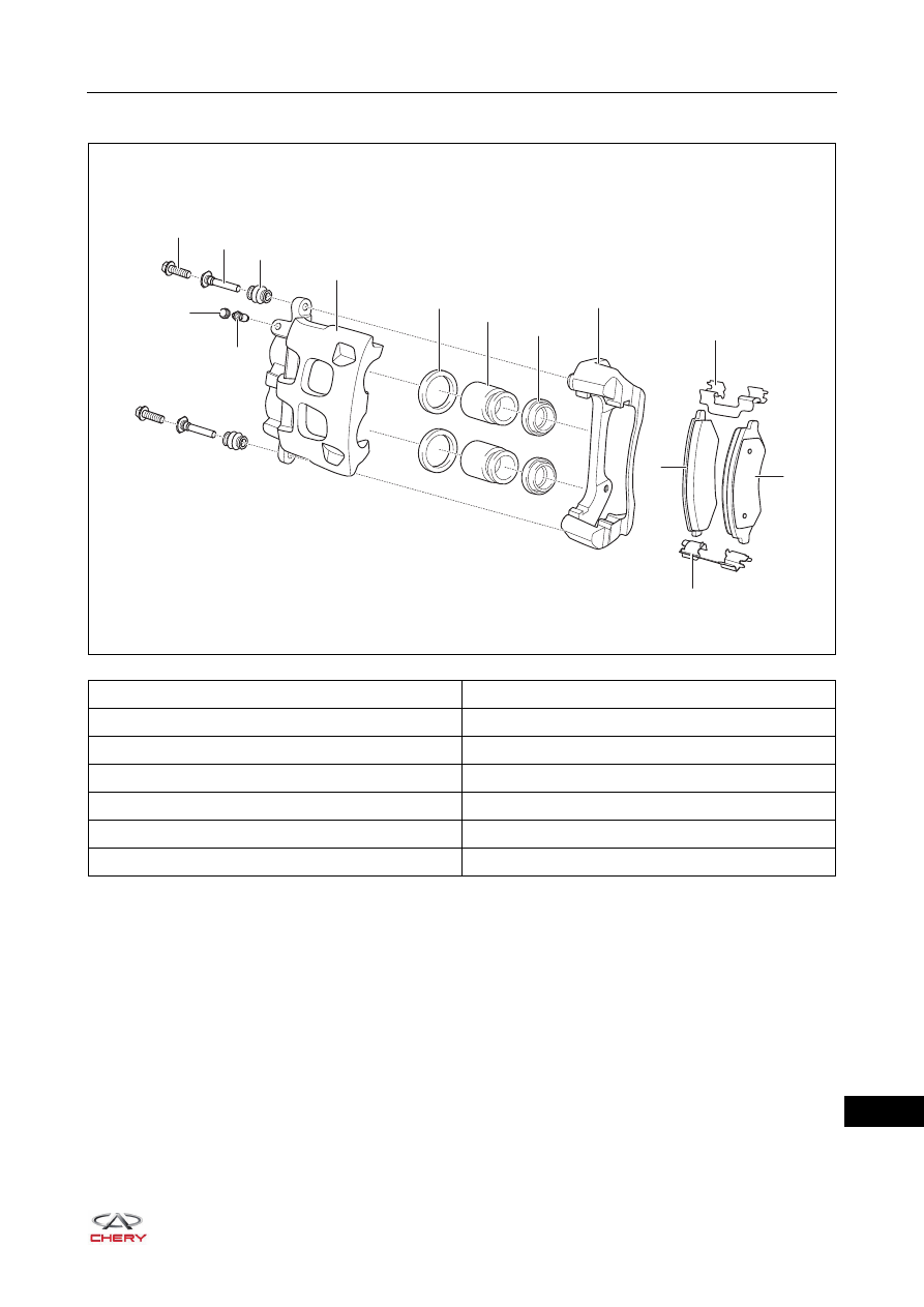
Front Disc Brake Assembly

1 - Brake Caliper Locating Bolt

2 - Brake Caliper Locating Bolt Guide Pin

3 - Brake Caliper Guide Pin Rubber Dust Boot

4 - Front Disc Brake Cylinder

5 - Front Disc Brake Piston Seal Ring

6 - Front Disc Brake Piston

7 - Front Disc Brake Piston Dust Boot

8 - Front Disc Brake Caliper Fixing Bracket

9 - Upper Support Gasket

10 - Inner Brake Lining

11 - Outer Brake Lining

12 - Lower Support Gasket

13 - Bleeder Plug

14 - Bleeder Plug Cap

RT21260310

1

2

3

11

12

13

10

14

4

5

6

7

8

9

26–

28

26

On-vehicle Inspection

1. Check brake disc runout.

a. Remove the front wheel (

See page 24-9

).

b. Secure the dial indicator (1) to the proper position. 

Position the dial indicator pointer approximately 10 
mm from the outer edge of brake disc.

c. Slowly rotate the brake disc (2) and check the runout. 

Mark the lowest and highest points and record these 
measurements. 

d. Check the runout on the opposite side of brake disc in the same way. Mark the lowest and highest 

points and record these measurements. 

e. Compare the recorded runout value and limit value.

Maximum runout for front brake disc: 0.06 mm

f. If runout exceeds the maximum value, replace the brake disc.

Removal

HINT:

 Use the same procedures for the right side and left side.

 Procedures listed below are for the left side.
1. Drain the brake fluid (

See page 26-13

).

2. Remove the front left wheel (

See page 24-9

).

3. Remove the front left brake caliper assembly.

a. Remove the coupling bolt and washer (arrow) 

between front left brake caliper assembly and front left 
brake hose assembly.

(Tightening torque: 27 ± 2 N·m)

RT21260320

2

1

CAUTION

 Wash off brake fluid immediately if it comes in contact with any paint surface.

ENVIRONMENTAL PROTECTION

 Drained brake fluid should be well kept in a container. Never discard it at will.

RT21260330

26–

29

26

b. Remove the coupling bolts (arrow) between front left 

brake caliper assembly and front left steering knuckle.

(Tightening torque: 100 ± 10 N·m)

c. Remove the front left brake caliper assembly.

4. Remove the front left brake disc.

a. Remove 2 positioning screws (arrow) from front left 

brake disc, and remove the front left brake disc.

(Tightening torque: 10 ± 1 N·m)

CAUTION

 DO NOT allow brake fluid to be sprayed on your clothes or skin when removing brake hose, as brake 

fluid is corrosive.

RT21260340

RT21260350

26–

30

26

Disassembly

HINT:

 Use the same procedures for the right side and left side.

 Procedures listed below are for the left side.

1. Remove the bleeder plug (w/ bleeder plug cap).

a. Remove the bleeder plug (w/ bleeder plug cap) 

(arrow) from brake caliper assembly.

2. Remove the brake cylinder assembly.

a. Remove 2 locating bolts (arrow) between brake 

caliper fixing bracket and brake cylinder assembly.

b. Detach the brake cylinder assembly and brake caliper fixing bracket.

3. Remove the front brake caliper locating bolt guide pin (w/ dust boot).

a. Remove 2 brake caliper locating bolt guide pins (w/ 

dust boot) (arrow) from brake caliper fixing bracket.

WARNING

 Never use high pressure when removing piston from the bore of brake caliper. Otherwise this may cause 

personal injuries.

 If it is needed to remove piston with compressed air. DO NOT face the piston to yourself or place your 

hands around the brake caliper and piston.

RT21260360

RT21260370

RT21260380


Content   ..  291  292  293  294   ..