Chery Tiggo 5 (T21). Service manual - part 291
 

  Index      Chery     Chery Tiggo 5 (T21) - service and repair manual 2014 year


Search            copyright infringement  


Content   ..  289  290  291  292   ..


Chery Tiggo 5 (T21). Service manual - part 291


26–

19

26

Vacuum Booster with Brake Master Cylinder Assembly

On-vehicle Inspection

1. Check vacuum booster assembly.

a. Air tightness check.

 Start engine and stop it after 1 or 2 minutes. Slowly depress brake pedal several times. 
 Make sure that booster is airtight. Check that distance every time the pedal depressed is gradually 

decreased compare to the previous operation.
If pedal operation is not as specified, check the check valve. If check valve is normal, replace the 
vacuum booster assembly.

 Start engine. Depress and hold pedal, then stop engine.
 Make sure that booster is airtight. Depress and hold pedal for 30 seconds, and check that pedal 

reserve distance does not change.
If pedal operation is not as specified, check the check valve. If check valve is normal, replace the 
vacuum booster assembly.

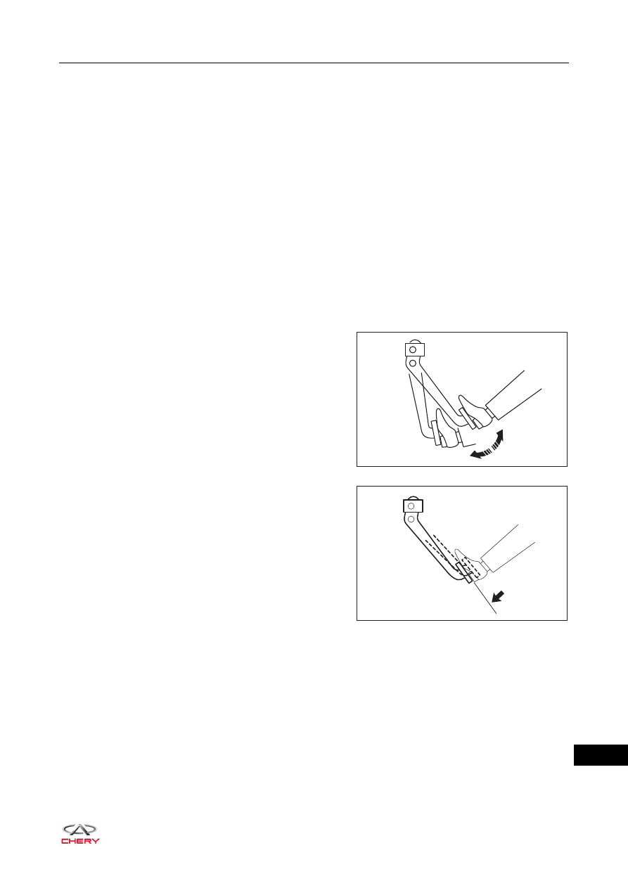
b. Operation check.

 Stop engine.
 Depress pedal several times and check that pedal 

reserve distance does not change.

 Depress and hold pedal, and then start engine. 

Check that pedal can only be depressed lightly.
If pedal operation is not as specified, check the 
check valve. If check valve is normal, replace the 
vacuum booster assembly.

RT21260160

RT21260170

26–

20

26

Removal

1. Drain the brake fluid (

See page 26-13

).

2. Remove the air filter assembly (

See page 10-17

).

3. Remove the vacuum booster with brake master cylinder assembly.

a. Loosen the brake fluid tube fixing clamp (arrow) and 

disengage the brake fluid tube from brake fluid 
reservoir assembly.

b. Loosen the clutch hose fixing clamp (arrow) and 

disengage the clutch hose from brake fluid reservoir 
assembly (for only MT model).

c. Loosen 2 coupling plugs (arrow) between brake 

master cylinder assembly and brake pipes.

(Tightening torque: 16 ± 2 N·m)

CAUTION

 Wash off brake fluid immediately if it comes in contact with any paint surface.

ENVIRONMENTAL PROTECTION

 Drained brake fluid should be well kept in a container. Never discard it at will.

RT21260100

RT21260110

RT21260120

26–

21

26

d. Disengage the vacuum hose assembly with check 

valve (arrow) from vacuum booster assembly.

e. Using needle-nose pliers, remove the locking pin 

(arrow) and pushrod pin (1) from vacuum booster 
pushrod, and detach the brake pedal assembly.

f. Remove 4 coupling nuts (arrow) between vacuum 

booster assembly and brake pedal assembly.

(Tightening torque: 25 ± 3 N·m)

g. Remove the vacuum booster with brake master 

cylinder assembly from engine compartment.

RT21260180

1

RT21260190

RT21260200

RT21260210

26–

22

26

Inspection

1. Check the check valve.

a. Remove the check valve from vacuum hose assembly.
b. Check that there is airflow (A) from vacuum booster to 

engine, and no airflow (B) from engine to vacuum 
booster.
If result is not as specified, replace vacuum hose 
assembly.

Installation

Installation is in the reverse order of removal.

B

A

RT21260220

CAUTION

 Make sure to tighten fixing plugs and nuts to the specified torque during installation. 
 Perform bleeding procedures for brake system and add brake fluid to proper level after completing 

installation.


Content   ..  289  290  291  292   ..