Chery Tiggo 5 (T21). Service manual - part 266
 

  Index      Chery     Chery Tiggo 5 (T21) - service and repair manual 2014 year


Search            copyright infringement  


Content   ..  264  265  266  267   ..


Chery Tiggo 5 (T21). Service manual - part 266


24–

7

24

ON-VEHICLE SERVICE

Tire Replacement

1. Remove the wheel (

See page 24-9

).

2. Use a tire remover to remove the tires according to the instructions.

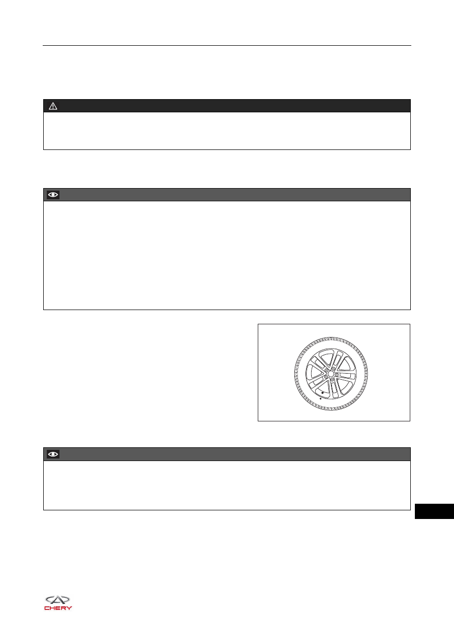
3. The white dot on tire edge must be aligned with the air 

cock on rim when installing the tires, as shown in the 
illustration.

4. Adjust tire pressure to the specified value.

WARNING

 Speed level of new replaced tire must meet the specified values for safe operation; otherwise the tire 

may blow out.

CAUTION

 Before installing air cock, check if air cock hole of wheel is smooth without any burrs, and apply glycerin 

to air cock rubber surface or soak air cock in glycerin fluid, and then using a tool to pull or press locating 
ring of air cock with force to pass it through the coke hole and install it into place (it is possible to use 
soapy water instead of glycerin).

 Apply glycerin or soapy water around tire before assembling the tires.
 When there is "dark point" mark on rim, align static balance "light point" testing mark or dynamic balance 

"light point" testing mark on tire with the "dark point" of rim.

 When there is no "dark point" mark on rim, align static balance testing mark or dynamic balance "light 

point" testing mark on tire with the air cock.

RT21240050

CAUTION

 Be sure to inflate tires as specified air pressure. The maximum air pressure cannot exceed 10% of rated 

air pressure during inflating the tire.

 Replace using specified standard tire with the same size and type.

24–

8

24

5. Check the contact surfaces among air cock, tire and rim for leakage.
6. Using a dynamic balancer, adjust the wheel balance (

See page 24-10

).

7. Install the wheel (

See page 24-9

).

(Tightening torque: 110 ± 10 N·m)

CAUTION

 Avoid scratching tires and rims when removing tires.
 Contact surface between tire and rim should be cleaned when installing tires.

24–

9

24

Wheel

Removal

1. Remove the wheel.

a. Stop the vehicle at a level ground and apply parking brake.
b. Using a tire wrench, loosen the wheel mounting bolts.
c. Firmly support and raise vehicle to a proper height.
d. Using a tire wrench, remove 5 wheel mounting bolts.

e. Remove the wheel.

Installation

1. Install the wheel.

a. Anticorrosion treatment is conducted on the contact surface between wheel and brake disc.
b. Install the wheel and pre-tighten the wheel mounting bolts by hand.
c. Using a torque wrench, tighten the wheel mounting 

bolts evenly to the specified torque in the order shown 
in the illustration.

(Tightening torque: 110 ± 10 N·m)

RT21240060

RT21240070

4

5

3

1

2

CAUTION

 DO NOT attempt to repair wheels by striking, heating or welding.
 Replace wheel mounting bolts with the special wheel mounting bolts, rather than those with different 

specifications or inferior quality.

 Be careful not to damage coating on wheel.
 To avoid damage to tire or over/under tightening the wheel mounting bolts, never use an impact wrench.
 DO NOT apply grease to wheel mounting bolts.
 To ensure wheel mounting bolts are tightened in place, wheel mounting nuts should be tightened after 

driving 100 km at the first time.

24–

10

24

Wheel Balance

Adjustment

1. Remove the wheel (

See page 24-9

).

2. Adjust tire pressure to the specified value.
3. Install the wheel to balancer with balance block removed. Install the balance shaft with mounting surface of 

wheel facing inward, choose a suitable taper body, and firmly lock the wheels using a locking device (align 
the taper body with center hole, otherwise data may be incorrect).

4. Turn on power source of balancer, and input parameters such as the measured distance from rim to 

balancer, rim width and rim diameter.

5. Put down the wheel protector, and proceed to balance test procedure automatically (start button should be 

pushed for some balancers). When the measurement is completed, unbalanced weight for both sides of 
tire will be displayed on the balancer automatically, and the wheel automatically brakes until it stops. Do 
not open the protector before stopping. Failure to do this may lead to accident.

6. According to the measurement result, corresponding 

balance blocks should be installed on the outside (1) and 
inside (2) of rim edge as shown in the illustration.

7. Perform the test again after assembly is completed, until the balancer displays 0.
8. After dynamic balance is completed, remove the wheel.

CAUTION

 Dynamic balancer must be calibrated before adjusting wheel balance.
 Remove impurities inside the tread pattern and original balance blocks to ensure wheel balance.

RT21240080

1

2

CAUTION

 When installing balance blocks, the final assembly unbalanced degree should be less than 200 g·cm, 

which means clamp type balance block of inside rim is 8 g and paste type balance blocks of outside rim 
is 10 g.

 DO NOT tap balance blocks forcibly when installing them in order to prevent balance blocks from 

deforming.

 DO NOT reuse deformed balance blocks, replace as necessary.


Content   ..  264  265  266  267   ..