Chery Tiggo 5 (T21). Service manual - part 65
 

  Index      Chery     Chery Tiggo 5 (T21) - service and repair manual 2014 year


Search            copyright infringement  


Content   ..  63  64  65  66   ..


Chery Tiggo 5 (T21). Service manual - part 65


06–

102

06

a. Measure the compression of misfiring cylinder (

See page 07-20

).

a. Replace the spark plug with a normally functioning one.
b. Perform spark test.

 Connect ignition coil connector.
 Connect spark plug and ignition coil, and ground spark plug housing.
 Start and run the engine for no more than 2 seconds, and check if spark is generated.

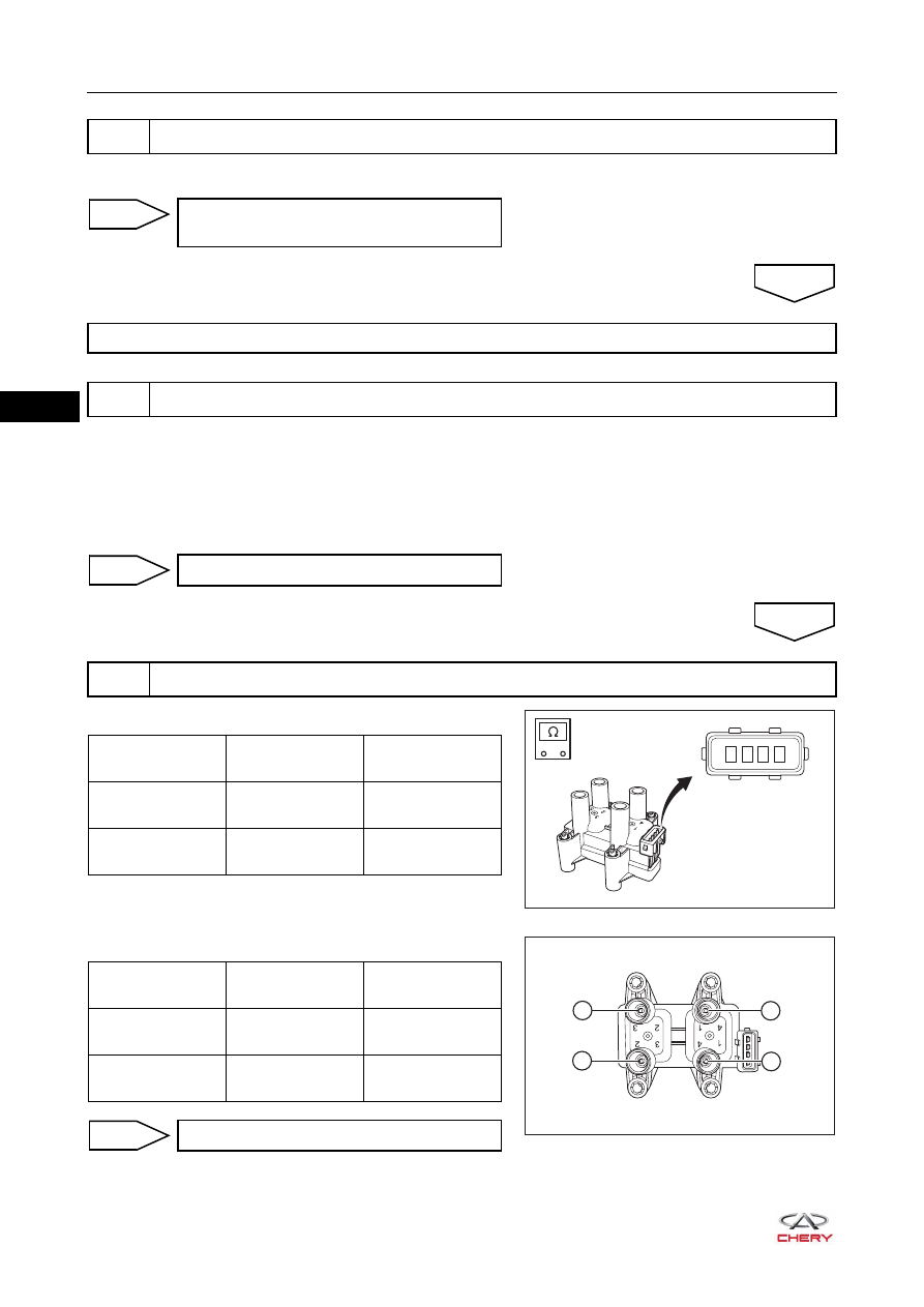
a. Check resistance of primary winding of ignition coil.

b. Check resistance of secondary winding of ignition coil.

5

Check compression of misfiring cylinder

Check engine to confirm cause of low 
compression

NG

Check injectors, valve clearance, intake system and fuel pressure, etc. of misfiring cylinder

6

Check spark of misfiring cylinder with a normally functioning spark plug

OK

Replace spark plug

OK

7

Check ignition coil

NG

RT21140070

1 2 3 4

-

+

Multimeter 

Connection

Condition

Specification (Ω)

Terminal 1 - 

Terminal 3

Normal 

temperature

0.50 - 0.64

Terminal 2 - 

Terminal 3

Normal 

temperature

0.50 - 0.64

2

3

4

1

RT21140080

Multimeter 

Connection

Condition

Specification 

(kΩ)

Post 1 - Post 4

Normal 

temperature

9.5 - 12.1

Post 2 - Post 3

Normal 

temperature

9.5 - 12.1

Replace ignition coil

NG

06–

103

06

a. Turn ignition switch to ON.
b. Check voltage between ignition coil connector terminals 

and body ground.

a. Turn ignition switch to LOCK.
b. Check fuse EF07 and main relay.
c. Check wire harness between ignition coil connector 

terminals and engine compartment fuse and relay box 
connector terminals. 
Check for Open

Check for Short

8

Check ignition coil power supply voltage

OK

1 2 3 4

E-018

-

+

V

RT21065039

Multimeter 

Connection

Condition

Specified 

Condition

E-018 (3) - Body 

ground

Ignition switch ON

11 to 14 V

Go to step 10

OK

9

Check ignition coil power supply circuit

NG

1 2 3 4

E-018

E-023

C1

C2

C3 C4

C5

C6

C7

C8 C9 C10

-

+

RT21065040

Multimeter 

Connection

Condition

Specified 

Condition

E-018 (3) - E-023 

(C4)

Always

Continuity

Multimeter 

Connection

Condition

Specified 

Condition

E-018 (3) or 

E-023 (C4) - Body 

ground

Always

No continuity

E-018 (3) or 

E-023 (C4) - 

Battery positive

Always

No continuity

06–

104

06

a. Turn ignition switch to LOCK.
b. Disconnect ECM connector E-035.
c. Check wire harness between ignition coil connector 

terminals and ECM connector terminals.
Check for Open

Check for Short

a. Use X-431 3G diagnostic tester to read the ECM DTC.
b. Refer to "DTC Confirmation Procedure".
c. Check if DTC P0300-00, P0301-00, P0302-00, P0303-00 or P0304-00 still exists.

Replace wire harness or connector 
(ignition coil - engine compartment fuse 
and relay box)

NG

10

Check ignition coil control circuit

OK

E-035

37 38 39 40 41 42 43 44 45 46

47

48

25 26 27 28 29 30 31 32 33 34

35

36

13 14 15 16 17 18 19 20 21 22

23

24

1

2

3

4

5

6

7

8

9 10

11

12

1 2 3 4

E-018

-

+

RT21065041

Multimeter 

Connection

Condition

Specified 

Condition

E-018 (1) - E-035 

(36)

Always

Continuity

E-018 (2) - E-035 

(35)

Multimeter 

Connection

Condition

Specified 

Condition

E-018 (1) or 

E-035 (36) - Body 

ground

Always

No continuity

E-018 (1) or 
E-035 (36) - 

Battery positive

Always

No continuity

E-018 (2) or 

E-035 (35) - Body 

ground

Always

No continuity

E-018 (2) or 
E-035 (35) - 

Battery positive

Always

No continuity

Repair or replace wire harness or 
connector (ignition coil - ECM)

NG

11

Check for DTCs

OK

06–

105

06

Replace ECM

NG

System is operating normally.
Reassemble vehicle and perform a road test to confirm that malfunction reported by customer has 
been repaired.

OK


Content   ..  63  64  65  66   ..