Alfa Romeo Stelvio MCA (2023 year). Manual in english - page 2
 

  Index      Manuals     Alfa Romeo Stelvio MCA (2023 year). Manual in english


Search            copyright infringement  


Content      ..      1      2      3      ..


Alfa Romeo Stelvio MCA (2023 year). Manual in english - page 2


43

humidity with unpleasant smells in the

passenger compartment.
When the state Start&Stop Evo is on

(engine off and car at a standstill), the

automatic recirculation management

may be turned off to prevent the

windows misting up, always taking air in

from outside, to reduce the probability

of the windows misting up (as the

compressor is off).

ELECTRIC WINDOWS

24)

They work with the ignition device in

the ON position and for about 3 minutes

after the ignition device has been turned

to the STOP position. When one of the

front doors is opened this operation is

disabled.

Driver side front door controls

The buttons are located on the door

panel trim. All windows can be controlled
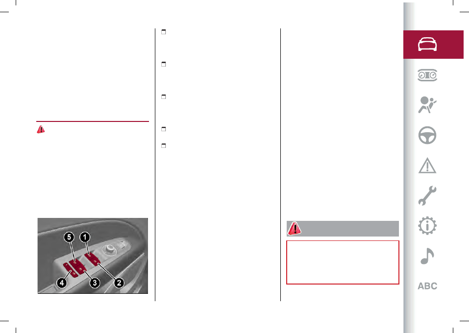
from the driver side door panel fig. 49.

49

04166V0001EM

(1): left front window opening/closing.

"Automatic continuous" operation during

window opening/closing and anti-pinch

system activated;

(2): right front window opening/closing.

"Automatic continuous" operation during

window opening/closing and anti-pinch

system activated;

(3): right rear window opening/closing;

"Automatic continuous" operation during

window opening/closing and anti-pinch

system activated;

(4): enabling/disabling of rear door

electric window controls;

(5): left rear window opening/closing;

"Automatic continuous" operation during

window opening/closing and anti-pinch

system activated.

Window opening

Push the buttons to open the desired

window.
Each button has two position steps.
Press gently (first position step) for

manual "burst" window travel, while

pressing the same button harder (second

position step) activates "continuous

automatic" operation.
If the button is pressed again, the

window will stop in the desired position.

Window closing

Lift the buttons to close the desired

window.

The window closing stage occurs

following the same logic described for

the opening stage both of the front door

windows and the rear door windows.

Window anti-pinch safety device

This safety system can recognise the

presence of any obstacle during the

window closing movement. If this

occurs, the system stops the window's

movement and reverts it, depending on

its position.
The anti-pinch safety function is

activated both during the manual and the

automatic operation of the window.

Electric window system initialisation

If power supply is interrupted, the

electric window automatic operation

must be reinitialised.
To perform the initialisation procedure,

which must be done on each door with

the doors closed, manually fully close the

window to be initialised.

WARNING

24)

Improper use of the electric windows

can be dangerous. Before and during their

operation, ensure that any passengers are

not at risk from the moving glass either

by personal objects getting caught in the

mechanism or by being hit by it directly.
CarManuals2.com

 GETTING TO KNOW YOUR CAR

44

ELECTRIC SUNROOF

(where provided)

25)

The electric sunroof comprises two

glass panels (the front one is mobile and

the rear one fixed) and is fitted with an

electrically operated front sun blind and

a manually operated rear sun blind.
Operation of the sunroof is only possible

with the ignition device at AVV.
The sun roof has three preset positions:

fully closed; comfort (intermediate

opening) fully open.
WARNING You cannot have the blind

closed when the roof is open.

OPENING

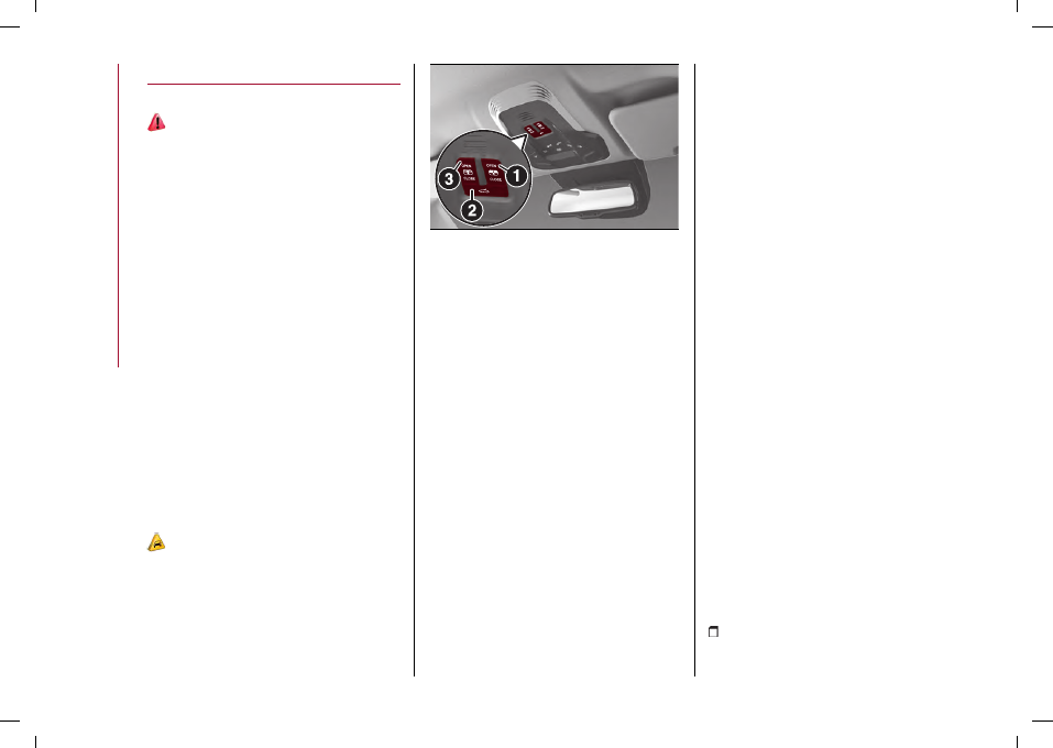
Press the button (1) fig. 50 at the word

OPEN

: the roof will open to the comfort

position. A second press will open it fully.
A long press of the same button will

open the roof until it is released, or if

held down, until it reaches the comfort

position. Use the button in the same way

to open the roof fully from that position.

10)

The automatic motion can be interrupted

in any position by pressing button

(1)again.
If the electric blind is closed, the roof

opening control opens it too.

50

04186S0075EM

CLOSING

From the fully open position, press the

button (1) at the word

CLOSE

: the roof

will close completely.
A long press of the same button moves

the roof until it is released.
The automatic motion can be interrupted

in any position by pressing button

(1)again.

SWIVEL OPENING

To bring the roof into "swivel" position,
press and release button (2) fig. 50.
This type of swivel opening can be

activated irrespective of the position of

the sun roof. When starting with the roof

in closed position, pressing the button

automatically causes its swivel-opening.

If the roof is already open, pressing the

button will open it to the swivel position.
Press button (2) again during automatic

opening or closing to stop movement of

the sunroof.

FRONT SUN BLIND ELECTRIC

MOVEMENT

The front sun blind is electrically

operated.
Press the button (3) fig. 50 at the word

OPEN

to open the sun blind.

Press the button (3) at the word

CLOSE

to close the sun blind.
The automatic motion can be interrupted

in any position by pressing button

(3)again.
If the roof is open, the sun blind closing

control will also close the roof.

ANTI-PINCH DEVICE

The sunroof has an anti-pinch safety

system capable of detecting the

presence of an obstacle during the

closing movement: if this happens, the

system intervenes and the movement of

the roof is immediately reversed into

opening.

INITIALISATION PROCEDURE

Automatic operation of the sunroof

must be initialised again in case of faulty

sunroof operation.
WARNING The anti-pinch safety function

is deactivated during the initialisation

procedure.
Proceed as follows:

Set the ignition device to AVV and

start the engine;

CarManuals2.com

45

press the button (1) at the word

CLOSE

to bring the roof to the fully closed

position;

open the driver side door
turn the ignition device to the STOP

position;

within 5 seconds, set the ignition

device to AVV and start the engine;

within 10 seconds press the button

(1) at the word

CLOSE

and hold it down;

after 10 seconds you will hear the electric

motors of the roof and blind stop in

sequence;

release the button and within 5

seconds press the button (1) at the word

CLOSE

and hold it down (until the end

of the cycle): the roof will automatically

perform a complete open and close cycle

including both the window and the blind

(to indicate that the initialisation has

been successful). If this does not occur,

the procedure must be restarted from

the beginning;

check that the re-initialisation

operation was successful by checking

the “one touch” function of the window

and blind.

WARNING

25)

When leaving the car, make sure to take

the key with you to avoid the risk of injury to

those still inside the car due to accidental

operation of the sunroof. Improper use

of the roof can be dangerous. Before and

during operation, always check that no-one

is exposed to the risk of being injured by the

moving sunroof or by objects getting caught

or hit by it.

IMPORTANT

10)

Do not open the sun roof if a roof rack

or crossbars are fitted. Do not open the sun

roof if there is snow or ice on it: you may

damage it.

BONNET

OPENING

26) 27)

Proceed as follows:

from inside the passenger

compartment, pull the release lever
fig. 51;

go to the outside of the vehicle and

position yourself in front of the grille;

slightly lift the bonnet and operate the

release device from the side from the

right leftwards as shown by the arrow,
fig. 52;

raise the bonnet completely: the

operation is facilitated by the presence

of two gas shock absorbers which hold it

the all open position.

51

04196V0001EM

52

9490104

CLOSING

26) 28)

To close, lower the bonnet to

approximately 40 centimetres from the

motor compartment then let it drop.

Make sure that the bonnet is completely

closed and not only fastened by the

locking device by trying to open it. If it is

not perfectly closed, do not try to press

the bonnet down but open it and repeat

the procedure.

CarManuals2.com

 GETTING TO KNOW YOUR CAR

46

WARNING Always check that the bonnet

is closed correctly to prevent it from

opening while the vehicle is travelling.

Since the bonnet is equipped with a

double locking system, one for each side,

you must check that it is closed on both

its side ends.

WARNING

26)

Perform these operations only when the

car is stationary.

27)

Use both hands to lift the bonnet. Before

lifting, check that the windscreen wiper

arms are not raised from the windscreen or

in operation, that the car is stationary and

that the electric parking brake is engaged.

28)

For safety reasons, the bonnet must

always be properly closed while driving.

Therefore, make sure that the bonnet

is properly closed and that the lock is

engaged. If you discover that the bonnet

is not perfectly closed while driving, stop

immediately and close the bonnet in the

correct manner.

TAILGATE

The tailgate is operated electrically,

so pay the utmost attention before

activating its movement.
Safe opening and closing of the

tailgate is guaranteed by a protection

system that can automatically stop

its movement when it encounters an

obstacle while opening or closing.
When the car is moving, tailgate

unlocking and movement are disabled.
To avoid difficulties in tight spaces, you

can set the height at which to block the

tailgate open.

Customising the tailgate opening

height

To customise the tailgate opening

position, proceed as described below:

open the tailgate;
manually move it to the position that

you want to store;

press one of the closing buttons (2)

or (3), fig. 53 for at least 5 seconds

(successful activation is indicated by the

direction indicators flashing three times).
The tailgate is now programmed to open

to the set position.
This function can be selected by acting
on the Connect system fig. 54.

53

04056V0055EM

54

12126V2600EM

Setting the tailgate opening height to a

preset position

(where provided)
To set the tailgate opening height to one

of the four preset positions, proceed as

follows:

activate the Main menu on the

Connect system and select the following

functions in sequence: "Settings", "Doors

and Locks" and "Electric Tailgate";

CarManuals2.com

47

select one of the four pre-set positions

and then press the graphic button to

activate the selected position.

OPENING

WARNING A beeper always sounds while

the tailgate is in motion.

Opening from the outside

When unlocked, you can open the tailgate

from outside the car by pressing the

electric opening button located between

the number plate lights for about one

second until you hear the unlocking click,
or by pressing the button

on the

remote control twice quickly.

55

04056V0005EM

The direction indicators will blink twice

and the internal lights will switch on when

the tailgate is opened. They switch off

automatically when the tailgate is closed.
The lights switch off automatically after

a few minutes if the tailgate is left open.

Opening from the inside

When it is locked, the tailgate can be

opened from inside the car by lifting
the button (1) fig. 56 on the driver’s door

panel trim.
WARNING You can stop the tailgate

moving by pressing the same button

again.

56

04206V0002EM

EMERGENCY OPENING FROM INSIDE

THE BOOT

There is a flap fig. 57 on the boot internal

trim, next to the tailgate lock, accessible

by folding down the rear seat backrest,

which allows access to the manual lock

opening cord.
Pull the cord to release the lock: the

tailgate can now be lifted manually.

57

04206V0014EM

CLOSING

Closing from outside

It is possible to close the tailgate by

pressing:

the button (2) fig. 53 on the tailgate

interior lining;

the button (3) fig. 53 on the tailgate

interior trim, (all the doors, including the

tailgate, will be locked);

the

button on the remote

control twice quickly;

the button fig. 55 on the tailgate,

between the number plate lights.
WARNING It is possible to stop the

tailgate moving with any of the close

buttons.

Closing from inside

Press the button (1) fig. 56 on the plate on

the driver’s door panel and hold it down

until the operation is complete.

CarManuals2.com

 GETTING TO KNOW YOUR CAR

48

WARNING It is possible to stop the

tailgate moving by releasing the button.

AUTOMATICALLY OPENING AND

CLOSING THE ELECTRICALLY

OPERATED TAILGATE IN

“HANDS-FREE” MODE

(where provided)
To operate the system in “hands-free”

mode, proceed as follows:

if the doors are locked or unlocked, the

system must recognise the electronic

key fob near the tailgate;

go to the rear of the car, in the centre

and about 50 cm from the tailgate;

move your foot under the bumper,

simulating a kick. When you have done

this movement, withdraw your leg. To

activate the movement, both sensors

must detect your leg fig. 58.

58

9490200

If it is closed, the electrically

operated/hands-free tailgate:

unlocks and opens completely;
with another movement of the foot, it

stops;

a further movement of the foot

reverses the direction and closes the

tailgate completely, if you do not stop it

again.
If it is open, with a movement of the foot,

the electrically operated/hands-free

tailgate:

closes completely;
another movement of the foot before

it closes completely will stop it;

if the tailgate was stopped, another

movement of the foot reverses the

direction and opens it completely.
You can activate/deactivate the

automatic tailgate opening and closing

function in hands-free mode on the

Connect system by activating the Main

menu and selecting the following items in

sequence: "Settings", "Doors and Locks"

and "Automatic tailgate opening".
WARNING Before lifting the foot off the

ground, make sure that you are in stable

position. Do not touch any part of the car.

There is a risk of injury from touching, for

example, the very hot exhaust system.
WARNING To conserve the battery

charge, avoid performing this operation

repeatedly with the engine off.
WARNING To prevent accidentally

opening the tailgate when washing the

car at a car wash station or using a

high-pressure cleaner, use the Connect

system to disable the “Automatic

tailgate opening” function.

TAILGATE INITIALISATION

WARNING If the battery is disconnected

or the protection fuse blows, the tailgate

opening/closing mechanism must be

reinitialised as follows:

close all the doors and the tailgate;
press the

button on the remote

control;

press the

button on the remote

control.

INTERIOR FITTINGS

GLOVE COMPARTMENT

29)

To open the compartment, use handle
fig. 59.
WARNING Do not insert objects of such

a size that the compartment cannot be

completely closed. Moreover make sure

that the compartment is completely

closed while driving.

CarManuals2.com

49

59

04246V0099EM

SUN VISORS

To direct the visor laterally, detach the

visor from the interior rear-view mirror

side hook and turn it towards the side

window fig. 60.

60

04246V0002EM

FRONT ARMREST

This is located between the front seats.
There is a storage compartment inside
the armrest: operate the fig. 61 device to

access and raise the armrest.

61

04246V0004EM

CUP / CAN HOLDER

Two cup/can holders are available in the
central tunnel fig. 62.

62

04246V0005EM

POWER SOCKETS

(where provided)
It is located on the central tunnel fig. 63

and inside the storage compartment on
the central tunnel fig. 64. It only operates

with the ignition device at ON.
It is possible to connect small battery-

powered appliances that have a

maximum power of 150W (e.g. cameras,

video cameras, tablets, razors, etc.) to

the socket.
WARNING Do not connect devices with

powers higher than 150W to the socket.

Do not damage the socket by using

unsuitable adaptors.

63

9490700

64

04026S0994EM

MOBILE PHONE COMPARTMENT

It is located on the passenger’s door

panel, in front of the door handle.

CarManuals2.com

 GETTING TO KNOW YOUR CAR

50

65

04246V0017EM

REAR CENTRAL ARMREST

The rear armrest is mobile and can be

stored in the backrest.

To lower it, pull on the tab located at

the top.

To re-close it, lift it until it is inserted in

its housing.
There are two cup/can holders and a
mobile phone compartment fig. 66 inside

the armrest.

66

04246V0018EM

WARNING The armrest was not designed

to support the weight of an adult

passenger or a child. Only use it to hold

drinks or small objects.

FIRE EXTINGUISHER

(where provided)
On some versions, there is a

fire extinguisher in the luggage

compartment.
For other versions/markets, the fire

extinguisher is located under the glove
compartment on passenger side fig. 67.

67

04246V0041EM

WARNING

29)

Do not travel with the storage

compartment open: it may injure the front

seat occupants in the event of an accident.

WIRELESS CHARGING SYSTEM -

WCPM (Wireless Charge Pad

Module)

(where provided)
The car can be equipped with the Qi®

wireless charger system (maximum

power available 15 W), located in the
housing in the front seat armrest fig. 68.
The Qi® wireless charger system is

designed to wirelessly charge your

mobile phone. Consult the manual of your

phone to check its compatibility.
Qi® is a standard interface that uses

electromagnetic induction to transmit

electrical energy to a mobile device.

The mobile phone must be designed in
accordance with the Qi® standard to be

recharged through the WCPM system.
WARNING Keys must not be placed on

the charging mat or within 15 cm from it.

This could cause excessive heat buildup

and damage to the remote control.
WARNING Placing the keys near the

Wireless charger may prevent the engine

from starting. In this case, a dedicated

message will be shown on the display of

the Connect system to alert the driver of

the need to remove the object from the

wireless charger.
WARNING Do not place the ignition key

or any other type of metal or magnetized

CarManuals2.com

51

object (e.g. credit cards, coins, etc.) inside

the mobile phone housing.
WARNING Make sure that you place

the mobile correctly (display facing

downwards) in the special charging

location: charging may not be enabled if

it is in the wrong position.
WARNING To avoid interference with the

key search, the wireless charger system

stops charging when any door is opened.
WARNING Make sure that there are no

metal objects between the phone and the

wireless charger system during charging.

Any such objects could overheat.

68

11116V0999EM

OPERATION

The wireless charging system is

activated in automatic mode when the

driver places his mobile phone in the

housing (WCPM) (see the previous

instructions), if the latter is compatible
with the Qi® standard.
If the mobile phone is removed from the

housing during the wireless charging

phase, this will automatically be

interrupted.
The wireless charger system enables

charging when all doors are closed

properly and the engine has been

started.
Interacting with the wireless charging

system, positioning the mobile phone in

the appropriate housing, the following

messages are shown on the Connect

system display (with specific icons and

widgets), to inform the driver about the

wireless charging system status:

"

Your phone is being charged

": is

displayed when the mobile phone is

positioned correctly in the wireless

charging compartment and the system is

activated correctly;

"

Phone fully charged

": is displayed

when the phone has completed charging

its battery;

"

Object not allowed

": is displayed

when a phone that is not enabled for

wireless charging or an object that is not

permitted (e.g. the ignition key) is placed.

"

Unavailable system

": appears when

there is a malfunction in the wireless

charger system.
The driver can deactivate the display

of messages relating to the operating

status of the wireless charging system,

using the relevant Connect system menu

(see the description on the dedicated

supplement).
NOTE The use of multiple wireless

functions on the smartphone at the same

time (Apple CarPlay/Android Auto and

wireless charging), as indicated by the

smartphone manufacturers, could cause

it to overheat, resulting in a limitation of

the active functions or its turning off. In

this case, it is recommended to connect

the system using the USB socket.

ENVIRONMENTAL PROTECTION

SYSTEMS

PETROL VERSIONS

The systems used for reducing petrol

engine emissions are: catalytic

converter, oxygen sensors, fuel

evaporation control system and GPF

particulate filter (petrol versions with

GPF only).

DIESEL VERSIONS

The systems used for reducing diesel

engine emissions are: exhaust gas

recirculation system (EGR), oxidising

catalytic converter,(DOC), selective

nitrogen oxide catalytic converter with
AdBlue® (SCR) and particulate filter

(DPF).

30)

CarManuals2.com

 GETTING TO KNOW YOUR CAR

52

GASOLINE PARTICULATE FILTER GPF

(Gasoline Particulate Filter) (petrol

versions with GPF only)

The Gasoline Particulate Filter is a

mechanical filter built into the exhaust

system, which physically traps carbon

particles present in the exhaust gases of

petrol engines.
Since this filter physically traps

particulate, it must be periodically

regenerated (cleaned) at regular

intervals by burning carbon particles.
The following may occur during

regeneration: more noise and/or

worsening of car handling.
These are not faults; they do not impair

normal car performance or damage the

environment. If the dedicated message

is displayed, see contents of "Warning

lights and messages" chapter in the

"Knowing the instrument panel” section.

DIESEL PARTICULATE FILTER (DPF)

(Diesel Particulate Filter)

The Diesel Particulate Filter is a

mechanical filter, integral to the exhaust

system, that physically traps carbon

particles present in the exhaust gases of

Diesel engines.
Since this filter physically traps

particulate, it should be periodically

regenerated (cleaned) at regular

intervals by burning carbon particles.

During the regeneration there may be

a limited increase in the engine idle

speed, fan activation, a limited increase

in fumes and high temperatures at the

exhaust.
These are not faults; they do not impair

normal car performance or damage the

environment. If the dedicated message

is displayed, see contents of "Warning

lights and messages" chapter in the

"Knowing the instrument panel” section.

WARNING

30)

The catalytic converter and particulate

filter (DPF) reach very high temperatures

during operation. Therefore do not park the

vehicle on flammable materials (e.g. grass,

dry leaves, pine needles, etc.): fire hazard.

CarManuals2.com

KNOWING THE INSTRUMENT PANEL

INSTRUMENT PANEL FEATURES . . . . . . . . . . . . . . . . . . . . . . . . . . . . . . . . . . . . . . 54
DISPLAY . . . . . . . . . . . . . . . . . . . . . . . . . . . . . . . . . . . . . . . . . . . . . . . . . . . . . . . . . . . . . . . . . . .60
TRIP COMPUTER . . . . . . . . . . . . . . . . . . . . . . . . . . . . . . . . . . . . . . . . . . . . . . . . . . . . . . . . .66
WARNING LIGHTS AND MESSAGES . . . . . . . . . . . . . . . . . . . . . . . . . . . . . . . . . . .68
EOBD SYSTEM (European On Board Diagnosis) . . . . . . . . . . . . . . . . . . . . . . .91

This section of the handbook provides all information that is

useful for getting to know, interpreting, and using the

instrument panel correctly.

CarManuals2.com

 KNOWING THE INSTRUMENT PANEL

54

INSTRUMENT PANEL FEATURES

“HERITAGE” DISPLAY

69

9490475

1. Speedometer / 2. Driving assistance system indications / 3. Customisable notification area, dipped/main beam headlight icons, side

lights, rear fog light / 4. Instantaneous speed (numerical), driving assistance system notification icons / 5. Customisable notification

area, engine torque limitation or external temperature display 6. Customisable and notification area with pop-ups / 7. Tachometer

/ 8. Digital engine oil temperature indicator / 9. Notification icon display area / 10. Gear shift indicator (GSI - Gear Shift Indicator) /

Automatic transmission information / 11. Menu title, screen navigation indications (e.g.: reset counters, customisation of information

display, etc.) / 12. Main screen with driving assistance system notifications or car speed display / 13. Operating mode display: Dynamic,

Normal, Advanced Efficiency / 14. Digital fuel level gauge, SBA (Seat Belt Alert) system indications, TPMS (Tyre Pressure Monitoring

System) notification symbol

CarManuals2.com

55

“EVOLVED” DISPLAY

70

9490477

1. Speedometer / 2. Driving assistance system indications / 3. Customisable notification area, main beam/dipped beam headlights,

side lights, rear fog lights icons, second instantaneous speed display / 4. Instantaneous speed (numerical), driving assistance system

notification icons / 5. Customisable notification area, engine torque limitation or external temperature display 6. Customisable and

notification area with pop-ups / 7. Tachometer / 8. Digital engine oil temperature indicator / 9. Notification icon display area / 10. Gear

shift indicator (GSI - Gear Shift Indicator) / Automatic transmission information / 11. Menu title, screen navigation indications (e.g.:

reset counters, customisation of information display, etc.) / 12. Main screen with driving assistance system notifications or car speed

display / 13. Operating mode display: Dynamic, Normal, Advanced Efficiency / 14. Digital fuel level gauge, SBA (Seat Belt Alert) system

indications, TPMS (Tyre Pressure Monitoring System) notification symbol

CarManuals2.com

 KNOWING THE INSTRUMENT PANEL

56

“RELAX” DISPLAY

71

9490433

1. Speedometer / 2. Driving assistance system indications / 3. Customisable notification area, dipped/main beam headlight icons, side

lights, rear fog light / 4. Instantaneous speed (numerical), driving assistance system notification icons / 5. Customisable notification

area, engine torque limitation or external temperature display 6. Customisable and notification area with pop-ups / 7. Tachometer

/ 8. Digital engine oil temperature indicator / 9. Notification icon display area / 10. Gear shift indicator (GSI - Gear Shift Indicator) /

Automatic transmission information / 11. Menu title, screen navigation indications (e.g.: reset counters, customisation of information

display, etc.) / 12. Main screen with driving assistance system notifications or car speed display / 13. Operating mode display: Dynamic,

Normal, Advanced Efficiency / 14. Digital fuel level gauge, SBA (Seat Belt Alert) system indications, TPMS (Tyre Pressure Monitoring

System) notification symbol

CarManuals2.com

57

"Race” DISPLAY (where provided)

72

9490217

1. Display of longitudinal/lateral acceleration trend and peaks of lateral acceleration / 2. Customisable notification area, dipped/main

beam headlight icons, side lights, rear fog light / 3. Gear shift indicator (GSI) / Automatic transmission information 4. Customisable

notification area, engine torque limitation or external temperature display 5. Notification icon display area / 6. Digital fuel level gauge,

SBA (Seat Belt Alert) system indications, TPMS (Tyre Pressure Monitoring System) notification symbol

CarManuals2.com

 KNOWING THE INSTRUMENT PANEL

58

DESCRIPTION OF THE INSTRUMENT

PANEL

NOTE The "Heritage", "Evolved" and

"Relax" views can be set by pressing the
"MENU VIEW" button fig. 73 on the right-

hand shift paddle. The 'Evolved' display is

the default setting.
NOTE The “Race” display is set by

selecting the “Race” mode on the Alfa

DNA™ Pro system. With the “Race”

display set, the speedometer and “Driver

Assistance” screens are deactivated

(only the Widget selection screen is

active). It is also not possible to change

the graphic display by pressing the

“MENU VIEW” button on the right-hand

steering wheel lever.
NOTE The graphics of the “Heritage” and

“Evolved” displays may vary depending

on the set-up.

73

9490235

SPEEDOMETER

The instantaneous speed of the car

(in km/h or mph) is displayed in this

position, which can also be displayed at

the top of the display.
Press the ring fig. 74 to switch between

km/h and mph scales.
NOTE In the "Natural" driving mode,

only the instantaneous speed, minimum

speed (0 km/h) and maximum speed at

full scale are displayed on the scale. The

colour of the speedometer may vary

according to the driving mode set by the

Alfa DNA™ Pro system.

74

9550195

For versions/markets, where applicable,

the secondary speed can also be shown

on the instrument cluster display.
With “Evolved” display active, three

different graphic animations are

provided:

with “Dynamic” mode active on the

graphic scale of the speedometer and

rev counter all numbers are displayed
fig. 75;

with “Natural” or “Advanced Efficiency”

mode active, the speed and engine speed

value will only be displayed when they
are reached or exceeded fig. 76;

the value “0”, maximum speed and

engine speed are always displayed.

75

9550400

76

9550401

CarManuals2.com

59

(Traffic Jam Assist) information

display

When Active Cruise Control (ACC), HAS

(Highway Assist) or TJA (Traffic Jam

Assist) are active, a dedicated icon is

displayed at the top of the tachometer,

which can be white (with device/systems

enabled and paused) or green (with
device/systems active) fig. 77.

77

9550240

TACHOMETER

This indicates the rpm of the engine

expressed in revolutions per minute. X

1000" or "X 100".
NOTE In the "Natural" driving mode,

only the instantaneous speed, minimum

speed (0 rpm) and maximum speed at

full scale are displayed on the scale. The
colouring of the indicator (1) fig. 78 may

vary depending on the driving mode set

via the Alfa DNA™ system.

78

9550502

DIGITAL FUEL LEVEL GAUGE

The digital indicator fig. 79 displays the

level of fuel still available in the tank and

the estimated indicative range.
The triangle to the side of the symbol

indicates the side of the car with the fuel

filler.
The symbol

turns yellow when the

level has reached the fuel reserve, while

the mark at the bottom of the scale turns

red fig. 80.
The indications next to the graphic scale

indicate the amount of fuel:

F

(Full) = full tank

E

(Empty) = empty tank

79

9550229

80

9550230

WARNING If the reserve switches on,

refuel at the earliest opportunity.
WARNING Do not travel with the fuel

tank almost empty: possible gaps in

fuel supply could damage the catalytic

converter.

ENGINE OIL TEMPERATURE GAUGE

The digital indicator fig. 81 displays the

temperature of the engine lubrication oil.
When the temperature is too high, the
icon

and the indicator turn red.

Active Cruise Control (ACC) / HAS system

(Highway Assist) / TJA system

CarManuals2.com

 KNOWING THE INSTRUMENT PANEL

60

81

9550228

INSTRUMENT PANEL LIGHT

ADJUSTMENT (brightness sensor)

Inside the tachometer there is a

light sensor capable of detecting

environmental light conditions and

adjusting the operating mode (night/day)

and the brightness of the instrument

panel and the Alfa Connect system

display.

DISPLAY

A welcome screen appears on the
instrument panel display, fig. 82 upon

entering the passenger compartment.

82

9550504

CENTRAL SCREEN

The following information is displayed in
the central area of the display fig. 83:

Speedometer (numeric indication)
Navigation (where provided)
Performance
Driver Assist
Messages and stored message list

NOTE In “Race” mode, only

“Performance” information and the

“Messages and stored message list” will

be displayed.
NOTE Turn the ignition device from the

STOP position to the MAR position to

display the last active screen before the

engine is switched off.

83

9550170

NAVIGATION BETWEEN SCREENS

Press the button (2) fig. 84 and turn the

ring (1) up or down to scroll through the

screens.
If the selected screen permits, press the

ring to access the submenus (1).

84

9550169

SPEEDOMETER

The following information fig. 85 is

displayed on this screen:

(1): instantaneous speed in km/h or

CarManuals2.com

61

mph. Press the ring (1) fig. 84 to switch

between km/h and mph scales.

(2): selected driving mode.
(3): messages.
(4): engaged gear and GSI (Gear Shift

Indicator) shift suggestions.

85

9650062

NAVIGATION

(where provided)
This screen can be used to repeat the

indications provided by the Alfa Connect

system navigator on the right-hand dial

of the instrument panel display.
Zoom changes made on the Alfa Connect

system are not automatically repeated

on the instrument panel display screen.
Turn the ring up/down (1) fig. 84 to

increase/decrease the zoom on this

screen. Press the ring to go back to

the initial frame. The zoom level is

automatically reset to the factory

settings whenever the engine is started.

If the function is activated using the Alfa

Connect system settings, the navigator

indications of the Alfa Connect system

are also repeated within the right dial of
the display (1) fig. 86 by means of turn by

turn instructions.
The following information is shown:

(1): direction indicators
(2): distance to next change of

direction (in km or miles, depending on

instrument panel settings)

(3): suggested lanes
(4): address of the road to be followed

after the change of direction
Press and hold the ring (1) fig. 84 to

disable the indications in the right-hand

ring for the current navigation.

86

9550407

With navigation active outside the

“Navigation” screen, turn indications

are displayed in the lower area of the

instrument cluster display in a pop-up

message each time the navigator

suggests a change of direction.
NOTE It is only possible to display the

repetition of navigation directions from

the native navigator of the Alfa Connect

system. The repetition of directions

provided by apps on the device

connected to the Alfa Connect system

through Android Auto, Apple CarPlay

or Baidu CarLife (for versions/markets,

where provided) is not supported.

PHONE

WARNING The Alfa Connect system

supports the pairing of two phones at

the same time but during the call only the

phone currently in use will be displayed

on the screen.
To start a call, proceed as follows:

press the ring (1) fig. 84 to access the

phone list

select the desired connected phone by

turning the ring up or down, then press

the ring again. To exit the screen, select

“Exit”;

to initiate the call to the desired phone

number, select the contact by turning

the ring up or down, then press the ring

again. To cancel without making a call

and return to the phone list, select "Exit".
The screen displays the status of the call
(fig. 87, fig. 88):
(1) Incoming call

CarManuals2.com

 KNOWING THE INSTRUMENT PANEL

62

(2) Outgoing call
(3) Any second simultaneous call and its

status (on-hold, outgoing, incoming, in

progress, ended)
(4) Call in progress
(5) Call ended

87

9550301

88

9550300

The screen also displays the arrival of a
message using the symbol

.

According to the display settings, an

incoming call can be notified via a pop-up
screen in the tachometer dial fig. 89.

The pop-up screen shows the following

information:

the name of the contact (or the phone

number if the contact is not stored on the

phone)

the image of the contact, if any (if

associated with the contact stored on

the phone)

the name of the telephone on which

the call is being received (only if two

telephones are connected at the same

time)
Press the button

or the ring (1) fig. 84

on the steering wheel to accept the

incoming call.
The pop-up screen remains displayed

until the call is accepted or the caller

ends the call.

89

9550403

PERFORMANCE

According to the mode selected using

the Alfa DNA™ system selector, the

screen shows the acceleration or fuel

consumption of the car.
Refer to the “Alfa DNA™ System” chapter

in the “Starting and driving” section for

more information

"DYNAMIC" MODE

The vehicle stability parameters are

displayed.
The graphs illustrate the trend of the

longitudinal/lateral accelerations (G-

meter information), considering gravity

acceleration as a reference unit.
Lateral acceleration peaks are displayed
on the right fig. 90.

90

9550175

“NATURAL” MODE

The average consumption value and

instantaneous consumption value are
displayed fig. 91.

CarManuals2.com

63

91

9550174

DRIVER ASSIST

The screen at fig. 92 shows the status

and settings of the driving assistance

Active Cruise Control, Lane Keeping

Assist and Traffic Jam Assist systems.
For further information see the

respective chapters in the "Safety" and

"Starting and driving" sections.
Any instant notifications are displayed

via a pop-up screen.
The units of measurement (metric or

imperial) depend on the units defined

using the display settings.

92

9490333

MESSAGES AND STORED MESSAGE

LIST

Messages shown on the display using

pop-up screens are stored as long as

they remain valid.
They can be view later in the central area
of the “Messages” screen (1) fig. 93.

93

9550438

If multiple messages are present:

press the ring (1) fig. 84 to access the

message list

scroll through the previous/next

messages by turning the ring up/down (1)

upwards/downwards. The position of

the displayed message within the list
is indicated by the light spot (2) fig. 93.

Presence of previous/next messages is

indicated by grey dots

CUSTOM AREAS

The right dial (tachometer) (2) fig. 94

and left dial (speedometer) (1) of the

instrument panel can be customised to

display additional information using the

"Settings" function of the Alfa Connect

system.
One of the following can be selected for

each dial:

Time
Date
External temperature
Compass (where provided)
Empty

94

9550404

CarManuals2.com

 KNOWING THE INSTRUMENT PANEL

64

NOTE The date and time format and the

unit of measurement of the external

temperature depend on the settings

defined using the Alfa Connect system.
NOTE It is not possible to display the

same information in two different dials:

setting the same content in one dial will

remove the information from the other.
NOTE If the repetition of the navigation

is deactivated (see the paragraph

"Navigation"), even if the compass is

shown on the instrument panel display, it

is not active.
When the engine is switched off, the

last customisation set is stored and is

displayed the next time the engine is

started.

WIDGETS

The right-hand dial (tachometer) of the

instrument panel can be customised

with alternative information to that

described in the previous paragraph

"Custom areas" using graphic elements

known as "Widgets".
To scroll through the set widgets, press
the button (2) fig. 84 on the steering

wheel controls and then turn the ring (1).
The following widgets can be displayed:

Media, which displays the following,

according to the type of information

played by the Alfa Connect system:

album thumbnail, source, song

title, artist, any connected phone

information, or:

album thumbnail or radio station

logo, station name, frequency,

any information on the connected

phone

95

9650081

Trip A, Trip B (if present) fig. 96,

distance travelled, average consumption

on trip, trip time, average speed,
odometer, AdBlue® level (Diesel

versions only) inside tank

Compass (where provided) fig. 97

96

9550405

97

9650082

NOTE The Compass is displayed

automatically if Trip B is disabled using

the display settings. Trip B, if enabled,

automatically replaces the compass

display.

Tyre pressure measured by the TPMS

(Tyre Pressure Monitoring System)

CarManuals2.com

65

98

9550168

POP-UP SCREENS

Under certain driving conditions,

messages or pop-up screens may be

automatically displayed on the right-

hand dial to alert the driver to useful

driving information (grey background,

e.g. notification of open doors, open
bonnet and/or tailgate, fig. 99), low

priority warnings (yellow background) or

high priority warnings (red background,
e.g. a braking indication, fig. 100).
Where applicable, the pop-up screen

display may be accompanied by an

acoustic signal and one or more warning

lights (or symbols) on the instrument

panel display.

99

9550408

100

9650080

NOTE In the case of two or more

simultaneous events displaying a pop-up

screen, the screens are displayed in

sequence and in order of priority:

first those with a higher priority

(red background), then those with a

lower priority (yellow background)

and then those with information (grey

background).
The pop-up screen can be closed by
holding the ring (1) fig. 84 pressed.

If the engine is shut down with one or

more faults present, pop-up warning

screens will be displayed the next time

the engine is restarted if these faults

have not been solved in the meantime.

ENGINE OIL LEVEL DISPLAY

The car is provided with an engine oil
level display system, fig. 101.
The oil level graphic bar, on the left-

hand side of the dial, is displayed when

starting/stopping the engine.
NOTE If the maximum engine oil level

is exceeded, all marks and the symbol

will be displayed in red. A dedicated

message will appears on the instrument

panel display.
NOTE If the engine oil level is low, the
last notch and the symbol

will be

displayed in red. A dedicated message

will appears on the instrument panel

display.

101

9550231

CarManuals2.com

 KNOWING THE INSTRUMENT PANEL

66

ENGINE OIL CHANGE INDICATOR

SYSTEM

(where provided)
The car is equipped with an engine oil

change indicator system.
A dedicated message appears on the

instrument panel display for a few

seconds to indicate the next scheduled

oil change interval.
The engine oil of the indicator system

is duty cycle based, which means the

engine oil change interval may fluctuate,

dependent upon your personal driving

style.

GEAR SHIFT INDICATOR

(where provided)
The Gear Shift Indicator (GSI) system

advises the driver to change gear

through a special indication on the
display fig. 102.
Through the GSI system, the driver is

informed that shifting gear will allow a

reduction in fuel consumption.

102

9550437

Icon

on the display: suggestion to

shift up a gear.

Icon

on the display: suggestion to

shift to two higher gears (double shift).

Icon

on the display: suggestion to

shift to a lower gear.

Icon

on the display: suggestion to

shift to two lower gears (double shift).
The indication in the display remains until

a gear is shifted or the driving conditions

go back to a situation where gearshifting

is not required to improve consumption.
When there are no gear shift

suggestions, the engaged gear is

displayed (P, R, N, D, M)

TRIP COMPUTER

The “Trip Computer” is used to display

information on car operation when the

ignition device is at MAR.
To display the Trip Computer, set it up as

a widget on the right dial (tachometer) of
the instrument panel fig. 103.

1

2

3

4

6

5

103

9550201

The "Trip Computer" has two

separate memories, "Trip A" and

"Trip B", where the data for the car's

"complete journeys" (trips) is recorded

independently from each other.
Press and release the button (2) fig. 104

button on the steering wheel controls

until the "Trip A" or "Trip B" widget is

highlighted on the instrument panel.

CarManuals2.com

67

104

9550194

The Trip Computer can display the
following information fig. 103:

odometer (1);
average fuel consumption (2);
average speed (3);
total distance travelled according to

the trip meter since the last reset (4);

the expected range before an

AdBlue® top-up is required (5);

the elapsed time since the trip meter

was last reset (6).

Actual running time

This indicates the total time travelled

since the last reset. The time is increased

when the ignition device is in the AVV

position.

Reset Trip

Hold the ring (1) fig. 104 pressed to clear

the displayed resettable function value.

CarManuals2.com

 KNOWING THE INSTRUMENT PANEL

68

WARNING LIGHTS AND MESSAGES

WARNING The warning light switches on in the instrument panel together with a dedicated message and/or acoustic signal when

applicable.These indications are indicative and precautionary and as such must not be considered as exhaustive and/or alternative

to the information contained in the Owner Handbook, which you are advised to read carefully in all cases. Always refer to the

information in this section in the event of a failure indication.
WARNING The failure indicators appearing on the display are divided into two categories: very serious and less serious failures.

Serious faults are indicated by a repeated and prolonged warning "cycle". Less serious faults are indicated by a warning "cycle" with

a shorter duration. You can stop the warning cycle in both cases by pressing the button located on the windscreen wiper lever. The

instrument panel warning light will stay on until the cause of the failure is eliminated.

WARNING LIGHTS ON INSTRUMENT PANEL

Possible detailed messages and/or acoustic signalling can be matched to a few warning lights and symbols.

Red warning lights

Warning light

What it means

INSUFFICIENT BRAKE FLUID / ELECTRIC PARKING BRAKE ON
The warning light switches on when the ignition device is brought to MAR, but it should switch off after a few seconds.

Low brake fluid level

The warning light turns on when the level of the brake fluid in the reservoir falls below the minimum level, possibly due

to a leak in the circuit. Restore the brake fluid level, then check that the warning light has switched off. If the warning

light stays on, contact an Alfa Romeo Dealership.

Electric parking brake on

The warning light switches on when the electric parking brake is engaged. In the event of failure, the warning light

flashes for about 10 seconds and then turns off. Release the electric parking brake, then check that the warning light

has switched off. If the warning light stays on, contact an Alfa Romeo Dealership.
If the car is parked on a gradient of more than 30% and/or the brake temperature is greater than 662°F (350°C), when

the parking brake is engaged, the warning light will flash to indicate a potentially unsafe condition.

CarManuals2.com

69

Warning light

What it means

EBD FAILURE
The simultaneous switching on of the

(red) and

(amber) warning lights with the engine on indicates either a

failure of the EBD system or that the system is not available. In this case, the rear wheels may suddenly lock and the

vehicle may swerve when braking sharply.
Drive very carefully to the nearest Alfa Romeo Dealership to have the system inspected immediately.

POWER STEERING FAILURE (where provided)
The warning light (where provided) switches on when the ignition device is brought to MAR, but it should switch off

after a few seconds.
If the warning light remains on, you could not have power steering and the effort required to operate the steering

wheel could be increased; steering is, however, possible.
Contact an Alfa Romeo Dealership as soon as possible.

AIRBAG FAILURE
If the warning light switches on constantly, this indicates a failure in the airbag system.

31) 32)

ALTERNATOR FAILURE
The switching on of the warning light with engine on indicates to an alternator failure. Contact an Alfa Romeo

Dealership as soon as possible.

DOORS OPEN
The warning light switches on when one or more doors are not completely shut. A pop-up screen appears highlighting

in red the door(s) that have not been closed properly instead of the tachometer dial. An acoustic warning is activated

with the doors open and the car moving. Close the doors properly.

CarManuals2.com

 KNOWING THE INSTRUMENT PANEL

70

WARNING

31)

If the

warning light does not switch on when the ignition device switch is moved to MAR or if it stays on while driving (together with the

message on the display), there might be a fault in the restraint systems; in this case, the airbags or pretensioners may not deploy in the event of an

accident or, in a lower number of cases, they could deploy erroneously. Before proceeding, contact an Alfa Romeo Dealership to have the system

checked immediately.

32)

The failure of the

warning light is signalled by the switching on of the

symbol on the instrument panel. In this case, the warning light may

not indicate problems with the restraint systems. Before proceeding, contact an Alfa Romeo Dealership to have the system checked immediately.

Amber warning lights

Warning light

What it means

ABS (Anti-lock Braking System) FAILURE
The warning light switches on to indicate an ABS (Anti-lock Braking System) fault. In this case the braking system

maintains its efficiency unaltered but without the advantage of the ABS system. Drive carefully and contact an Alfa

Romeo Dealership as soon as possible.

ESC (Electronic Stability Control) SYSTEM

ESC system activation

Intervention by the system is indicated by the flashing of the warning light: it indicates that the car is in critical stability

and grip conditions.

ESC system failure

If the warning light does not switch off, or if it stays on with the engine on, a failure was found in the ESC system.

Contact an Alfa Romeo Dealership as soon as possible.

Hill Start Assist failure

The warning light switches on to indicate a Hill Start Assist system failure. Contact an Alfa Romeo Dealership as soon

as possible.

CarManuals2.com

71

Warning light

What it means

PARTIAL / TOTAL DEACTIVATION OF ACTIVE SAFETY SYSTEMS
When the ignition device is brought to ON, the warning light switches on, but should switch off as soon as the engine is

started.
The warning light switches on to indicate that some active safety systems have been partially or totally deactivated.

When the systems are reactivated, the warning light switches off.
For further details about the active safety systems see the "Active safety systems" chapter in the "Safety" section.

When the active safety systems are reactivated, the warning light switches off.

FCW (Forward Collision Warning) SYSTEM FAILURE
The warning light turns on to indicate a failure in the Forward Collision Warning system. Contact an Alfa Romeo

Dealership as soon as possible.

FCW (Forward Collision Warning) SYSTEM DEACTIVATION
The warning light turns on if the Forward Collision Warning system has been deactivated or if the system is

obstructed/dirty/unavailable.

CarManuals2.com

 KNOWING THE INSTRUMENT PANEL

72

Warning light

What it means

EOBD / INJECTION / CATALYST DAMAGE (petrol versions with GPF)
In normal conditions, when the ignition device is brought to ON, the warning light switches on, but it should switch off

as soon as the engine is started.
The operation of the warning light may be checked by the traffic police using specific devices. Comply with the laws

and regulations of the country where you are driving.

Injection system failure

If the warning light remains on, or it switches on whilst driving, the injection system is not working properly.
The warning light on constantly signals a malfunction in the supply/ignition system which could cause high exhaust

emissions, a possible loss of performance, poor driveability and high consumption.
The warning light switches off if the malfunction disappears, but is still stored by the system.
Under these conditions, you can continue travelling at moderate speed but without demanding excessive effort from

the engine or high speed. Prolonged use of the car with the warning light on constantly may cause damage. Contact an

Alfa Romeo Dealership as soon as possible.

Catalytic converter damage

If the warning light flashes, it means that the catalytic converter may be damaged. Release the accelerator pedal to

lower the speed of the engine until the warning light stops flashing.
Continue the journey at moderate speed, trying to avoid driving conditions that may cause further flashing and contact
an Alfa Romeo Dealership as soon as possible.

11)

AdBlue® (UREA) INJECTION SYSTEM FAILURE (Diesel versions)
In normal conditions, when the ignition device is brought to MAR, the warning light switches on, but it should switch off

as soon as the engine is started.
The warning light appears if a fluid not conforming with nominal features is introduced or if an average AdBlue®

(UREA) consumption of over 50% is detected.
In this case, contact an Alfa Romeo Dealership as soon as possible.
If the problem is not solved, a dedicated message will appear on the instrument panel display whenever the next

threshold is reached, until it is no longer possible to start the engine.
When there are approximately 124 miles (200 km) before you can no longer restart the engine, on some versions a

dedicated message will appear fixed on the instrument panel display accompanied by warning tone.

CarManuals2.com

73

Warning light

What it means

ELECTRIC PARKING BRAKE FAILURE (where provided)
In normal conditions, when the ignition device is brought to MAR, the warning light switches on, but it should switch off

as soon as the engine is started.
The warning light turns on to indicate a failure in the electric parking brake system.
This failure could partially or completely block the car because the electric parking brake could remain activated even

if automatically or manually disengaged using the relevant controls.
If the car can still be used (electric parking brake not engaged), drive carefully to the nearest Alfa Romeo dealership,

remembering that the electric parking brake will not work.

33)

WARNING

33)

If a failure is present with sharp braking, the rear wheels may lock and the vehicle may swerve.

IMPORTANT

11)

If, turning the ignition device to MAR, the

warning light does not turn on or if it turns on steadily or flashing while driving (on some versions

together with the message on the display), contact an Alfa Romeo Dealership as soon as possible.

Green warning lights

Warning light

What it means

What to do

LEFT DIRECTION INDICATOR
The warning light switches on when the direction

indicator stalk is moved upwards or, together with the

left direction indicator, when the hazard warning light

button is pressed.

CarManuals2.com

 KNOWING THE INSTRUMENT PANEL

74

Warning light

What it means

What to do

RIGHT DIRECTION INDICATOR
The warning light switches on when the direction

indicator stalk is moved upwards or, together with the

left direction indicator, when the hazard warning light

button is pressed.

Warning light

What it means

BRIGHTNESS SENSOR
This warning light on the odometer lights up in the event of the brightness sensor activation.

Warning

What it means

All warning lights off

INSTRUMENT PANEL DISPLAY FAILURE
All warning lights remain off in the event of an instrument panel display failure. In this case, contact an Alfa Romeo

Dealership.

Message to have the

warning light checked

CONTROL SYSTEM WARNING LIGHT FAILURE
Failure of the control system warning light is indicated by a dedicated message appearing on the instrument panel

display. In this case, contact an Alfa Romeo Dealership.

CarManuals2.com


Content      ..      1      2      3      ..