Lotus Evora. Instruction - part 3


  Index      Lotus     Lotus Evora - service repair instruction 2009 year


Search            


Content   ..  1  2  3  4  ..


Lotus Evora. Instruction - part 3


Lotus Service Notes   


     Section AJ

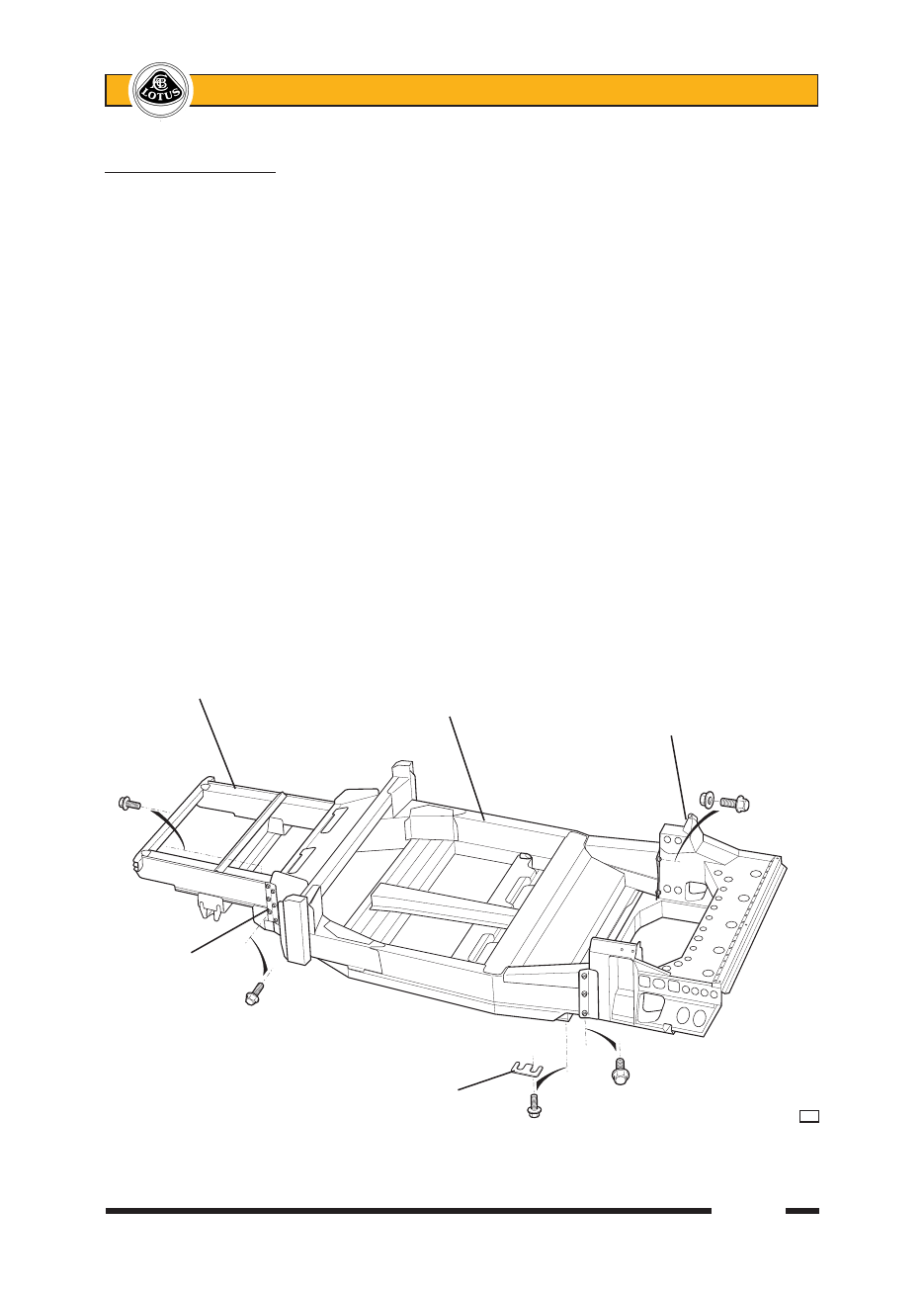
AJ.3 - REAR SUBFRAME

The rear ends of the chassis siderails are linked by a fabricated sheet steel subframe which provides 

mountings for the powertrain, rear suspension, rear body, exhaust muffler and seat belt mounting frame struts.  

The subframe is aligned to each of the siderails by an 8mm roll pin, and secured by seven M10 x 30, 8.8 grade 

bolts.  It is possible to remove the subframe from the chassis complete with powertrain and suspension attached, 

although access to some fixing bolts will be restricted, and alignment on refitment may be difficult.

To remove/refit rear subframe

1.  Remove rear body and disconnect all pipes, hoses, harnesses and cables. 

2.  Remove the seat belt mounting frame rear struts.  

3.  Support the rear subframe before progressively and evenly removing the seven fixing bolts from each side 

of the frame:


At each side;


- Two bolts from beneath into threaded inserts in the chassis rail lower surface;


- Three bolts into captive nuts in the chassis rail side face;

- Two bolts from within the engine bay using loose nuts ahead of the siderail closing plate.

4.  Withdraw the subframe taking note of the shim plates fitted at each side between the bottom of the siderail 

and the subframe. 

5.  On re-assembly, first trial fit the subframe to the chassis, using no shim plates.  Locate the subframe by 

engaging the roll pins into the dowel holes in the chassis rail rear closing plates and secure at each side 

by temporarily fitting the two bolts and nuts through the closing plates.  Measure the gap between the 

bottom of each chassis siderail and the subframe horizontal surface, and select the appropriate number 

of 1mm shim plates.

      Front subframe (alloy)

                              Main chassis tub (alloy)

                                                    Rear subframe (steel)

  Tie plate

                          Shim plate


a32


Lotus Service Notes   


     Section AJ

6.  Re-assemble the subframe to the chassis using Duralac MSDS anti-corrosion compound (A111C6017S) 

between the mating faces and inserting the appropriate shim stacks.  Fit all fixing bolts and tighten evenly 

and progressively to a final torque of 45 Nm.

AJ.4 - FRONT SUBFRAME

The front subframe uses the same construction techniques as the main chassis tub, with aluminium alloy 

extrusions bonded and riveted together to provide mounting points for the front suspension, front body clam-

shell and cooling radiators, and also houses the heating/a.c. system.  The subframe legs are secured at each 

side to the front face of the chassis tub by three bolts, and reinforced by a tie plate on the outer surface which 

uses six bolts.

To remove/refit front subframe

Before removing the front subframe, it is recommended to remove all front bodywork, the front suspension 

assembly and the HVAC equipment in order to allow easier handling of the subframe and to minimise potential 

component damage.

1.  Remove the front clamshell, 'A' panels and front bumper.

2.  Recover the a.c. refrigerant and drain the engine cooling radiator.  Remove the HVAC unit (see section 

PN) and disconnect all hoses, pipes, harnesses and cables.

3.  Disconnect the steering column from the rack pinion shaft.

4.  Provide support for the subframe before releasing the six bolts securing the tie plate to each subframe 

leg.  Then progressively and evenly release the three bolts securing the inboard side of each subframe 

leg to the chassis.  Withdraw the subframe.

5.  On re-assembly, mate the subframe to the chassis and locate with the three bolts and each side.  Fit the 

tie plates to the outboard faces and locate the six bolts at each side.  Progressively and evenly tighten all 

18 off M10x30 bolts to a final torque of 45 Nm.


Lotus Service Notes   


     Section AJ


Lotus Service Notes   


    Section BU

BODYCARE & REPAIR

SECTION BU

                                                     Sub-Section   Page

    General Description                                    BU.1      3

    Lotus Composite Body Features                            BU.2      3

    Bodycare                                           BU.3      4

    Accident Damage Assessment                              BU.4      5

    Body Panel Bonding Materials                              BU.5      6

    Replacement of Bonded-On Panels - General                    BU.6      9

    Roof Panel                                          BU.7      9

    Windscreen Frame                                     BU.8      10

    Body Side Panels                                      BU.9      11

    Rear Bulkhead                                        BU.10     12


Content   ..  1  2  3  4  ..