Snowmobile Ski-Doo CROSSOVER E-TEC AND EFI SERIES. OPERATOR’S GUIDE (2024) - page 2
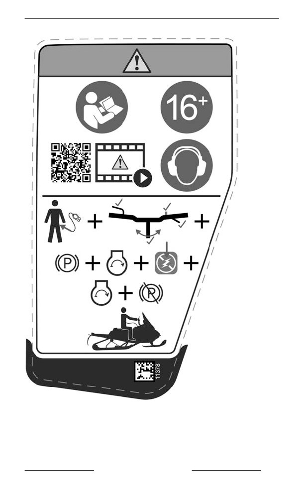
IMPORTANT ON-PRODUCT LABELS (ALL COUNTRIES EXCEPT CANADA/
UNITED STATES)
STARTING PROCEDURE – WARNING LABEL
SAFETY INFORMATION
111
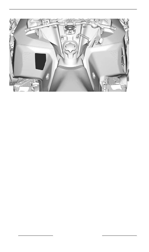
IMPORTANT ON-PRODUCT LABELS (ALL COUNTRIES EXCEPT CANADA/
UNITED STATES)
112
SAFETY INFORMATION
IMPORTANT ON-PRODUCT LABELS (ALL COUNTRIES EXCEPT CANADA/
UNITED STATES)
Passenger Safety - Warning Labell
WARNING
Remember: you are responsible of the safety of your
passenger.
All drivers and passengers must read the following:
– Always wear an approved helmet and clothing appropriate
for snowmobiling.
– Operate defensively, scan constantly for people, objects,
conditions and upcoming vehicles.
– Avoid surprise, be on the look out for the unexpected.
– Use extra caution whenever off-trail.
– Avoid thin ice/ open water.
– Never ride under the influence of alcohol or drugs, even as
passenger.
–
This vehicle is design for one (1) operator and as many passen-
gers as there are seats with straps or handgrips installed on the
vehicle conforming to SSCC standards.
When riding with a passenger:
– Braking ability and steering control are reduced.
– Decrease speed and allow extra space to maneuver.
– Adjust suspension according to weight.
SAFETY INFORMATION
113
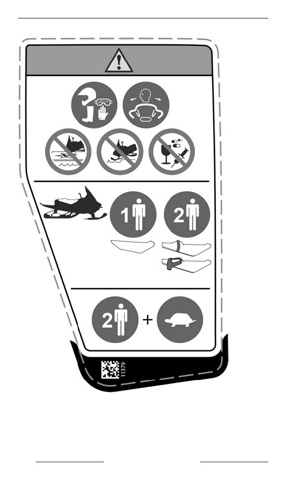
IMPORTANT ON-PRODUCT LABELS (ALL COUNTRIES EXCEPT CANADA/
UNITED STATES)
PASSENGER SAFETY – WARNING LABEL
114
SAFETY INFORMATION
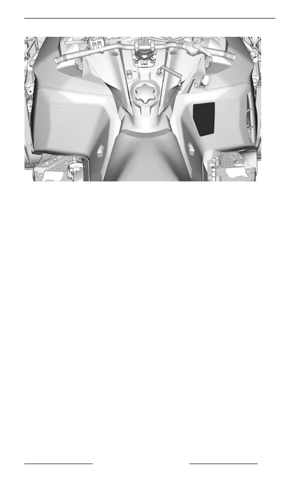
IMPORTANT ON-PRODUCT LABELS (ALL COUNTRIES EXCEPT CANADA/
UNITED STATES)
SAFETY INFORMATION
115
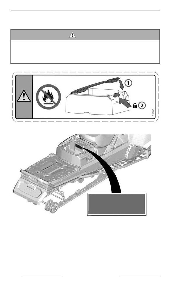
IMPORTANT ON-PRODUCT LABELS (ALL COUNTRIES EXCEPT CANADA/
UNITED STATES)
Rear Storage Compartment - Warning Label
WARNING
To reduce the risk of severe injury or death:
– Never carry flammable or dangerous liquids inside cargo
box. If ignited, this can lead to an explosion.
– Make sure the cover is closed and latched before riding.
REAR STORAGE COMPARTMENT - WARNING LABEL
TYPICAL
116
SAFETY INFORMATION
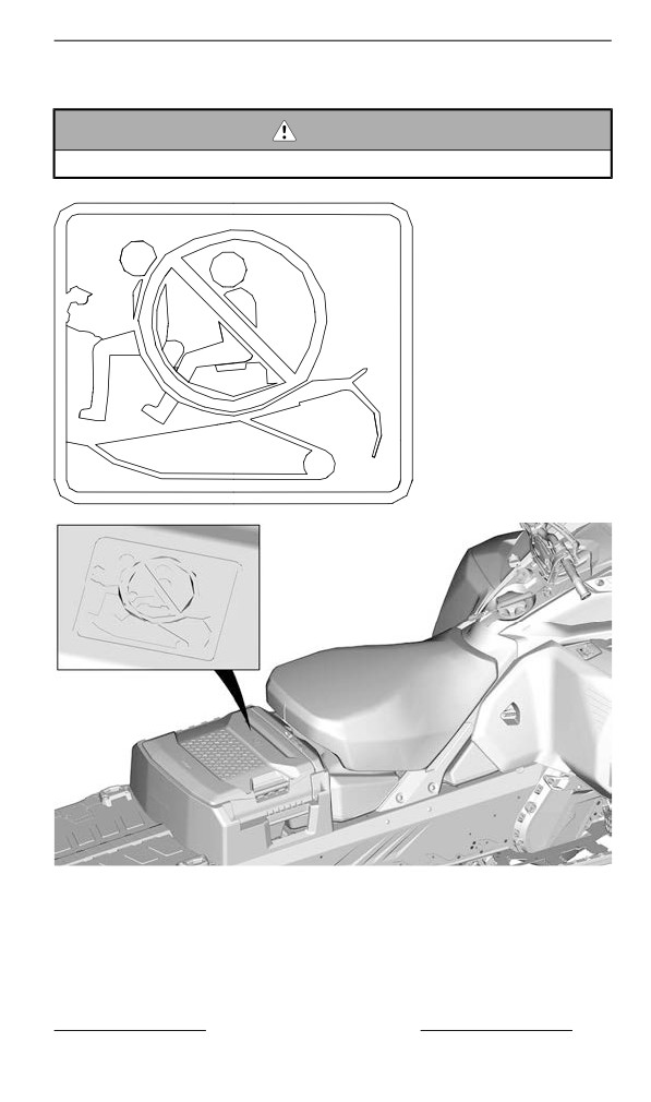
IMPORTANT ON-PRODUCT LABELS (ALL COUNTRIES EXCEPT CANADA/
UNITED STATES)
Molded Safety Piictogram
WARNING
Never carry passengers on the rear storage compartment.
SAFETY INFORMATION
117
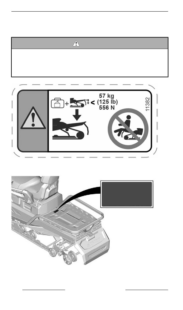
IMPORTANT ON-PRODUCT LABELS (ALL COUNTRIES EXCEPT CANADA/
UNITED STATES)
Maximum Cargo Load and Tongue Weiight Capacity
— Warniing Label
WARNING
– Exceeding maximum cargo may affect steering control,
braking ability and cause permanent damage.
– MAXIMUM cargo load (including tongue weight): 57 kg (556
N)
– MAXIMUM tongue weight: 16 kg (156 N)
MAXIMUM CARGO LOAD AND TONGUE WEIGHT CAPACITY
— WARNING LABEL
118
SAFETY INFORMATION
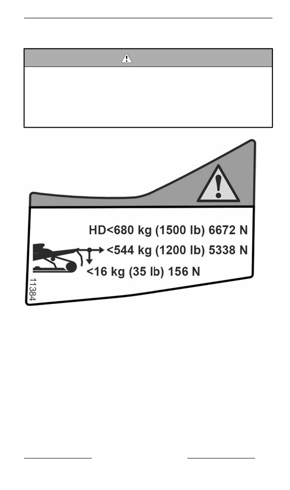
IMPORTANT ON-PRODUCT LABELS (ALL COUNTRIES EXCEPT CANADA/
UNITED STATES)
Maxiimum Towing Capacity - Warning Labell
WARNING
– Always use a securely fastened rigid tow bar to tow.
– Refer to the operator''s guide for more details.
– Exceeding maximum cargo may affect steering control,
braking ability and cause permanent damage.
– MAXIMUM tongue weight: 16 kg (156 N)
– MAXIMUM towing capacity (HD bumper): 680 kg (6672 N)
– MAXIMUM towing capacity (STD bumper): 544 kg (5338 N)
MAXIMUM TOWING CAPACITY - WARNING LABEL
SAFETY INFORMATION
119
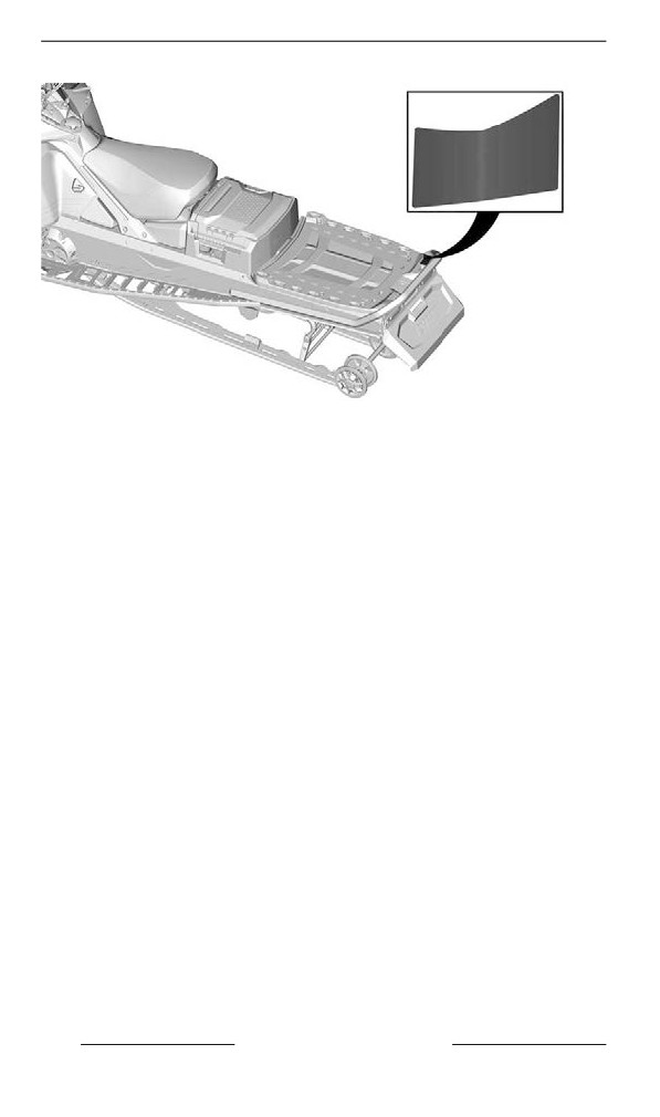
IMPORTANT ON-PRODUCT LABELS (ALL COUNTRIES EXCEPT CANADA/
UNITED STATES)
LABEL LOCATION — TYPICAL
120
SAFETY INFORMATION
IMPORTANT ON-PRODUCT LABELS (ALL COUNTRIES EXCEPT CANADA/
UNITED STATES)
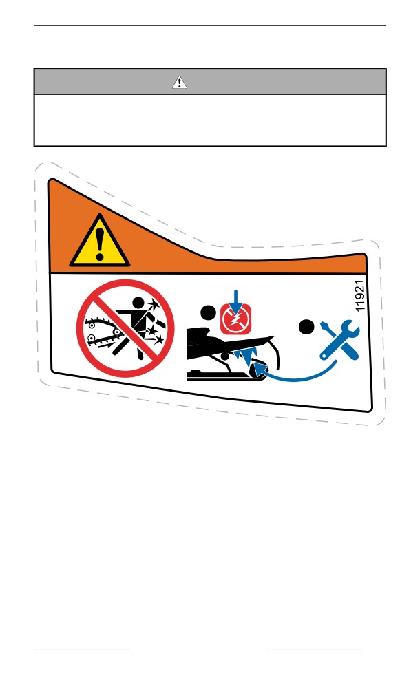
Rotatiing Track – Warniing Labell
WARNING
- NEVER stand behind or near a rotating track. Debris could be
projected causing severe injuries.
- To remove packed snow/ ice, stop the engine, lift and hold ve-
hicle on the side and use tools stored on the drive belt guard.
1
2
ROTATING TRACK – WARNING LABEL
SAFETY INFORMATION
121
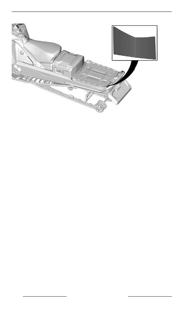
IMPORTANT ON-PRODUCT LABELS (ALL COUNTRIES EXCEPT CANADA/
UNITED STATES)
LABEL LOCATION — TYPICAL
122
SAFETY INFORMATION
IMPORTANT ON-PRODUCT LABELS (ALL COUNTRIES EXCEPT CANADA/
UNITED STATES)
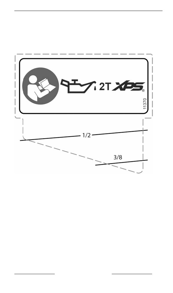
Techniical Informatiion Labels
Recommended Oil - Notice Label
Refer to the Technical Specifications for appropriate injection oil type
for your vehicle engine.
RECOMMENDED OIL - NOTICE LABEL
SAFETY INFORMATION
123
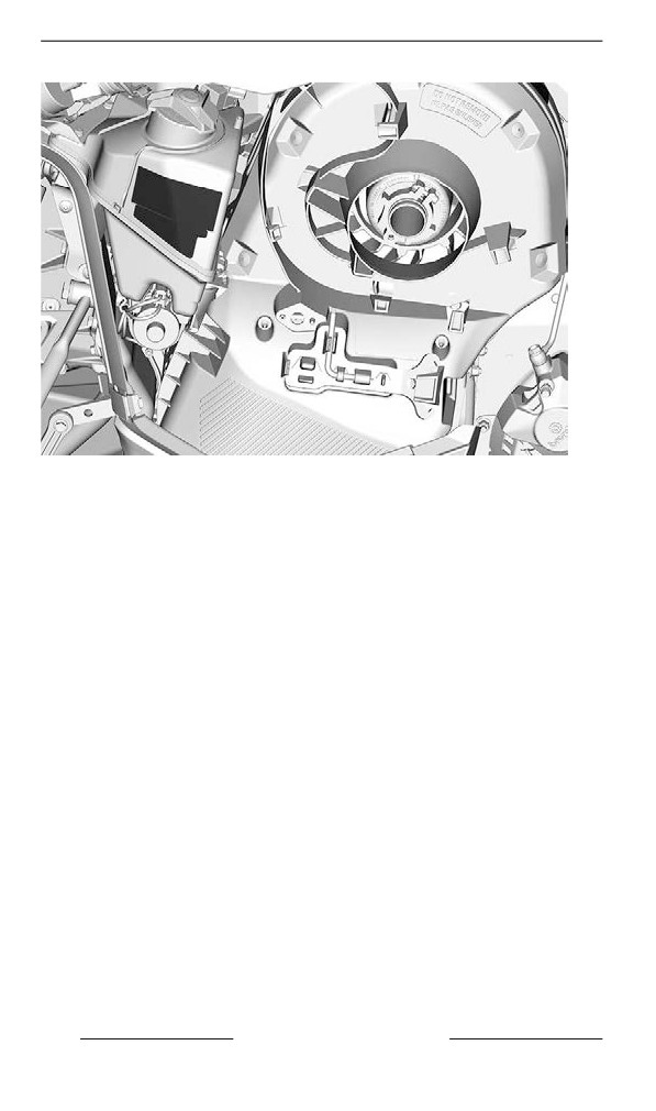
IMPORTANT ON-PRODUCT LABELS (ALL COUNTRIES EXCEPT CANADA/
UNITED STATES)
124
SAFETY INFORMATION
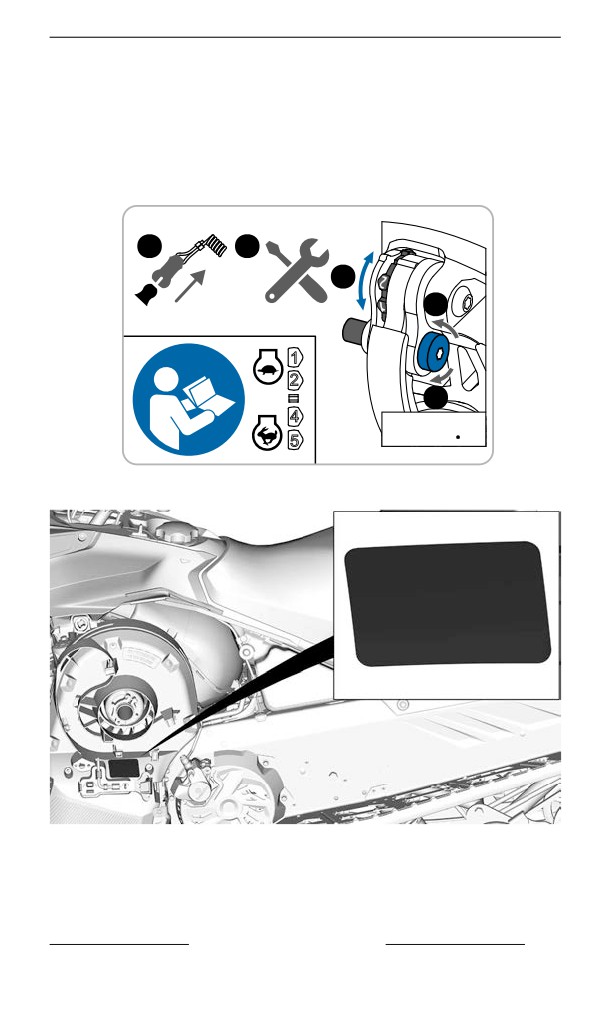
IMPORTANT ON-PRODUCT LABELS (ALL COUNTRIES EXCEPT CANADA/
UNITED STATES)
Clicker Adjustment Label
1. Remove tether cord.
2. Remove pulley expander from pulley guard.
3. Loosen bolt.
4. Adjust clicker.
5. Torque bolt.
1
2
4
3
1
2
5
4
( 7 @ 9 Nm )
( 62 @ 80 lb in )
5
CLICKER ADJUSTMENT LABEL
TYPICAL
SAFETY INFORMATION
125
IMPORTANT ON-PRODUCT LABELS (ALL COUNTRIES EXCEPT CANADA/
UNITED STATES)
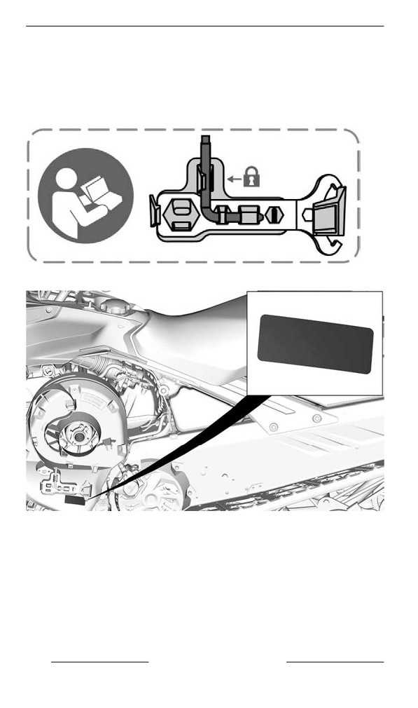
Adjustment Tools Label
- Install suspension adjustment tool first. (Illustrated red on label)
- Install pulley expander and Headlight adjustment tool second. (Il-
lustrated blue on label)
- Refer to Tools in Equipment.
ADJUSTMENT TOOLS
TYPICAL
126
SAFETY INFORMATION
IMPORTANT ON-PRODUCT LABELS (ALL COUNTRIES EXCEPT CANADA/
UNITED STATES)
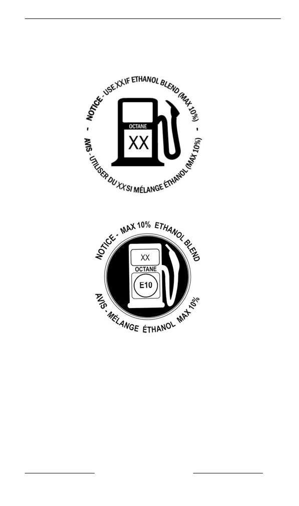
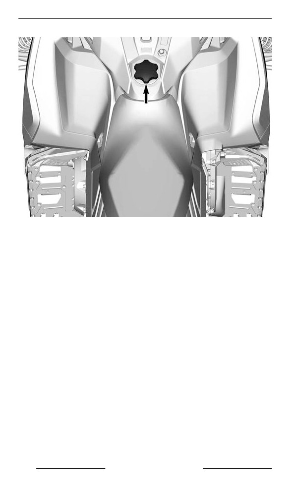
Recommended Fuel — Notice Label
Refer to the Technical Specifications for appropriate fuel type for your
vehicle engine.
AKI (RON+MON)/2 OCTANE RATING - NOTICE LABEL
RON OCTANE RATING - NOTICE LABEL
SAFETY INFORMATION
127
IMPORTANT ON-PRODUCT LABELS (ALL COUNTRIES EXCEPT CANADA/
UNITED STATES)
128
SAFETY INFORMATION
PRE-RIDE INSPECTION
Perform a pre-ride inspection before each ride to detect potential prob-
lems during operation. The pre-ride inspection can help you monitor
wear and deterioration before they become a problem. Correct any
problems that you discover to reduce the risk of an accident or a
malfunction.
Before Starting the Engiine
1. Remove snow and ice from body including lights, seat, footrests,
controls and instruments.
2. Remove packed snow and ice from the rear suspension using the
wrench tool stored on the drive belt guard.
3. Verify that air silencer prefilter is free of snow.
4. Verify that skis and steering operate freely. Check corresponding
action of skis versus handlebar.
5. Check fuel and injection oil for levels and leaks. Replenish if neces-
sary and in case of any leaks; you should seek service from an au-
thorized BRP snowmobile dealer, repair shop, or person of your
own choosing for maintenance, repair, or replacement.
6. All storage compartments must be properly latched and they must
not contain any heavy or breakable objects. Hood and side panels
must be also properly latched.
7. Activate the throttle control lever several times to check that it oper-
ates easily and smoothly. It must return to idle position when
released.
8. Activate the brake lever and make sure the brake fully applies be-
fore the brake control lever touches the handlebar grip. It must fully
return when released.
9. Apply parking brake and check if it operates properly. Leave park-
ing brake applied.
10. Inspect drive belt condition and height. Refer to drive belt in main-
tenance procedures.
After Engiine is Started
For proper engine starting procedure, refer to the appropriate Engine
Starting Procedure.
1. Check headlights high beam and low beam, taillight, stop light and
pilot lamps operation.
NOTE:
You may need to detach tether cord from your clothes to check lights.
In such a case, attach cord as soon as you get back at the controls of
the snowmobile.
2. Check the engine cut-off switch (by pulling tether cord cap) and
emergency engine stop switch operation.
3. Release parking brake.
4. Refer to Vehicle warm up and follow instructions.
SAFETY INFORMATION
129
PRE-RIDE INSPECTION
Pre-Ride Check List
ITEM
OPERATION
ü
BODY INCLUDING
SEAT, FOOTRESTS,
Check condition wear and remove
LIGHTS, AIR FILTER,
snow or ice .
CONTROLS AND
INSTRUMENTS
SKIS AND STEERING
Check for free movement and proper
ACTION
operation.
Check for proper operation and
SKI RUNNERS
abnormal wear.
FUEL
Check for proper level and no leaks.
INJECTION OIL (IF
Check for proper level and no leaks.
APPLICABLE)
COOLANT
Check for proper level and no leaks.
Check for cracks, fraying or abnormal
DRIVE BELT
wear and proper height.
THROTTLE LEVER
Check for proper operation.
BRAKE LEVER
Check for proper operation.
PARKING BRAKE,
Check for proper operation.
BRAKE
BRAKE FLUID
Check for proper level and no leaks.
STORAGE
Check for proper latching and no
COMPARTMENT
heavy or breakable objects.
Check condition and remove snow or
ice.
TRACK
For studded tracks, refer to Traction
Enhancing Products.
Check for proper operation and
SLIDER SHOES
abnormal wear.
130
SAFETY INFORMATION
PRE-RIDE INSPECTION
EMERGENCY ENGINE
STOP SWITCH AND
Check for proper action. Tether cord
ENGINE CUT-OFF
must be attached to operator clothing
SWITCH (TETHER
eyelet.
CORD CAP)
LIGHTS
Check for proper operation.
HORN BUTTON (IF
Check for proper operation.
EQUIPPED)
SAFETY INFORMATION
131
REPORTING SAFETY DEFECTS
In Canada, if you believe that your vehicle has a defect which could
cause a crash or could cause injury or death, you should immediately
inform Transport Canada in addition to notifying Bombardier Recrea-
tional Products Inc.
If Transport Canada receives similar complaints, it may open an inves-
tigation, and if it finds that a safety defect exists in a group of vehicles,
it may order a recall and remedy campaign. However, Transport Can-
ada cannot become involved in any individual problems between you,
your dealer or Bombardier Recreational Products Inc.
To contact Transport canada:
819-994-3328 (Gatineau-Ottawa area or internationally)
Toll free : 1 800-333-0510 (in Canada)
Transport Canada - ASFAD
330 Sparks Street
Ottawa, ON
K1A 0N5
132
SAFETY INFORMATION
VEHICLE
INFORMATION
133
PRIMARY CONTROLS
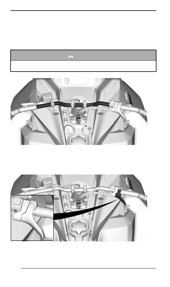
Handllebar
The handlebar controls the steering of the snowmobile. As the handle-
bar is rotated to right or left, the skis are turned right or left to steer the
snowmobile.
WARNING
Fast reverse while turning, could result in loss of stability and
control.
TYPICAL
Throttlle Lever
Throttle lever is located on the RH side of handlebar.
TYPICAL
134
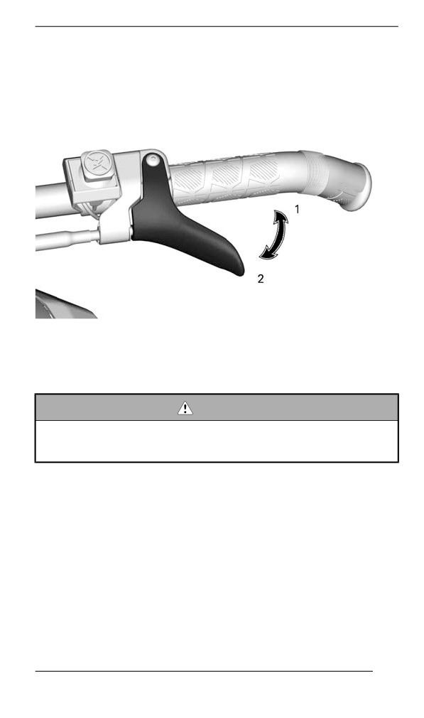
PRIMARY CONTROLS
Designed to be thumb activated. When squeezed, it increases the en-
gine speed. When released, engine speed returns automatically to
idle.
CABLE THROTTLE LEVER
1. To accelerate
2. To decelerate
WARNING
Test the throttle lever operation each time before starting the
engine. The lever must return to the rest position once re-
leased. Otherwise, do not start engine.
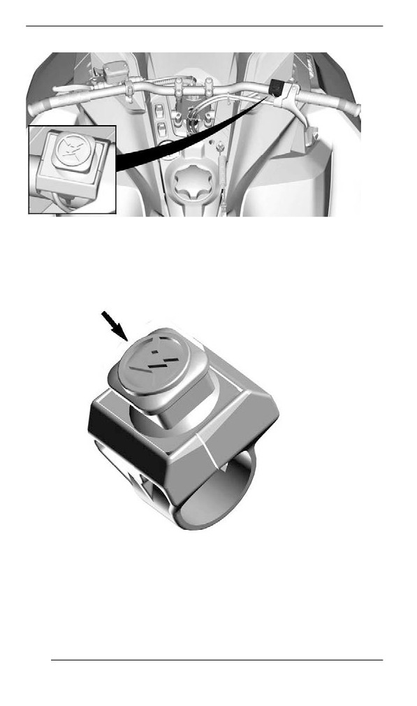
Emergency Engine Stop Switch
The emergency engine stop switch is located on the RH side of
handlebar.
135
PRIMARY CONTROLS
TYPICAL
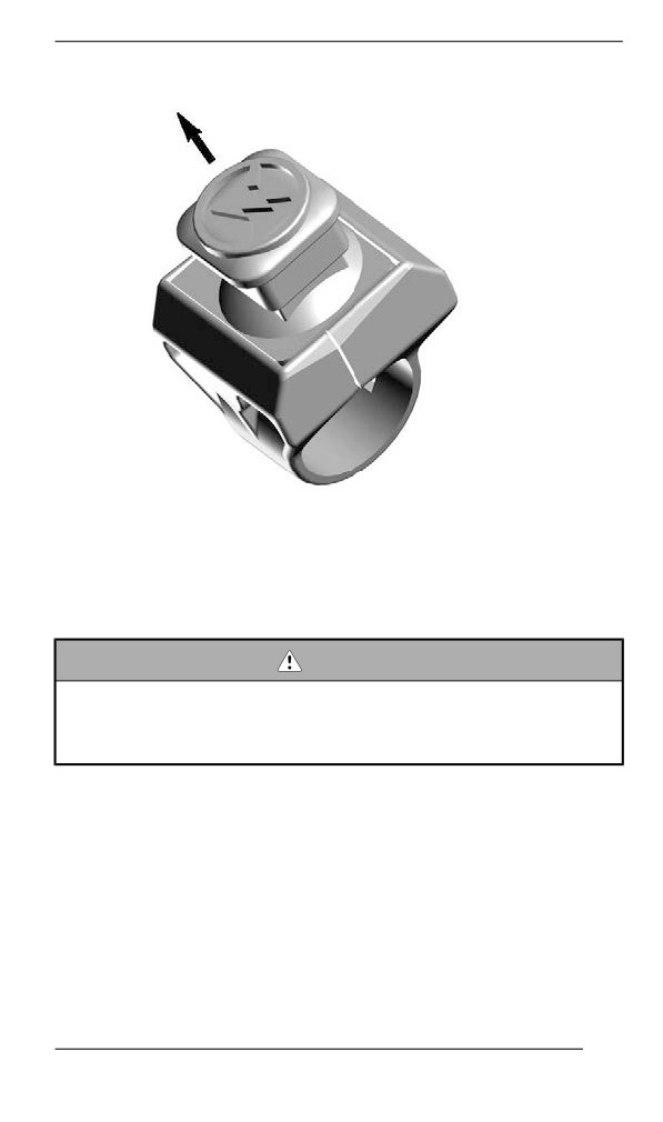
To stop the engine in an emergency, push the switch down in OFF po-
sition and simultaneously apply the brake.
OFF POSITION
To allow engine starting, pull the switch up in ON position.
136
PRIMARY CONTROLS
ON POSITION
All operators of the snowmobile should familiarize themselves with the
function of the emergency engine stop switch by using it several times
on first outing and whenever stopping the engine thereafter. This en-
gine stopping procedure will become a reflex and will prepare opera-
tors for emergency situations requiring its use.
WARNING
If the switch has been used in an emergency caused by a sus-
pected malfunction, the source of the malfunction should be de-
termined and corrected before restarting engine. Visit an
authorized BRP snowmobile dealer for servicing.
Brake Lever
Brake lever is located on the LH side of handlebar.
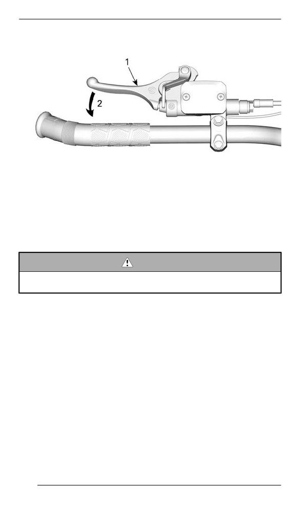
When squeezed, brake is applied. When released, it automatically re-
turns to the rest. Braking effect is proportional to the pressure applied
on the lever and to the type of terrain and its snow coverage.
137
PRIMARY CONTROLS
TYPICAL
1. Brake lever
2. To apply brake
Brake Lever Adjustment
WARNING
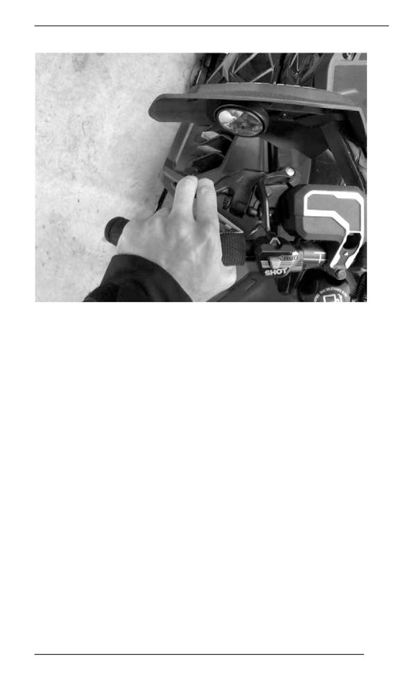
It is important to adjust the brake lever to the user size and nor-
mal riding position.
Proper brake lever position should allow:
- Good support for the index and middle finger on the lever.
- Use the outer end of the lever to optimize the force.
- Proper wrist alignment.
Taking the time to adjust and try out the brake lever before your first
snowmobile outing improves user comfort.
138
PRIMARY CONTROLS
Adjusting the Brake Lever
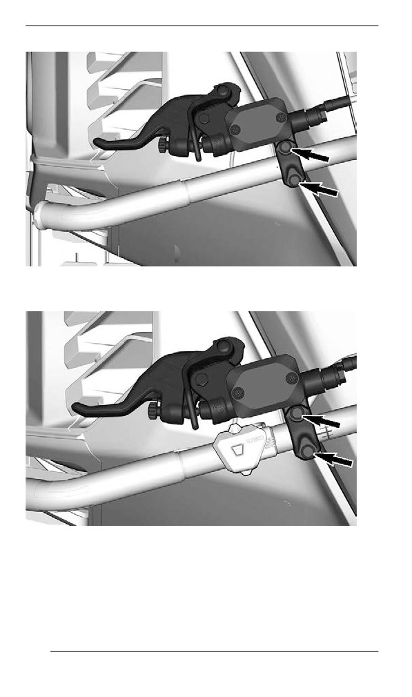
1. Loosen the two bolts enough to easily move the brake lever on the
handlebar.
NOTE:
If the two bolts are not loosen enough the brake lever can leave marks
on the handlebar.
Models with steel handlebar
139
PRIMARY CONTROLS
Models with aluminum handlebar and without multifunction
switch
Models with aluminum handlebar and with multifunction
switch
140
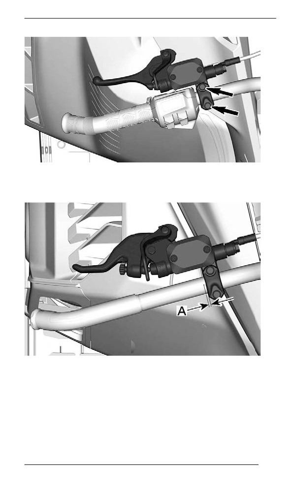
PRIMARY CONTROLS
2. Locate the reference mark on the handlebar and respect the dis-
tance and rotation limits.
Models with steel handlebar
A. 0 to 5 mm (0 to 0.197 in) between the handlebar point and side of
the brake lever
Models with aluminum handlebar and without multifunction
switch
141
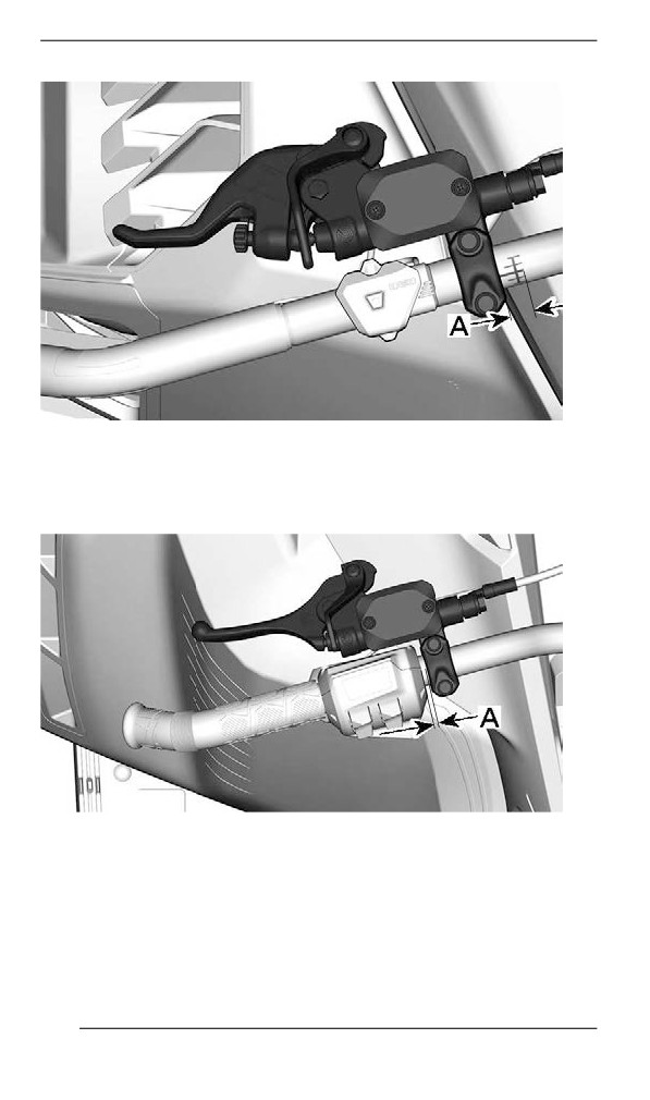
PRIMARY CONTROLS
A. 0 to 9 mm (0 to 0.354 in) between the start of the handlebar mark
and side of the brake lever
Models with aluminum handlebar and with multifunction
switch
A. 0 to 15 mm (0 to 0.590 in) between the side of the multifunction
switch and the side of the brake lever
3. With the operator on the driver seat, put the brake lever in the de-
sired position.
4. Tighten the two bolts to specification.
142
PRIMARY CONTROLS
TIGHTENING TORQUE
Brake lever adjustment
8.5 ± 1.5 Nm (75 ± 13 lbf-in)
bolts
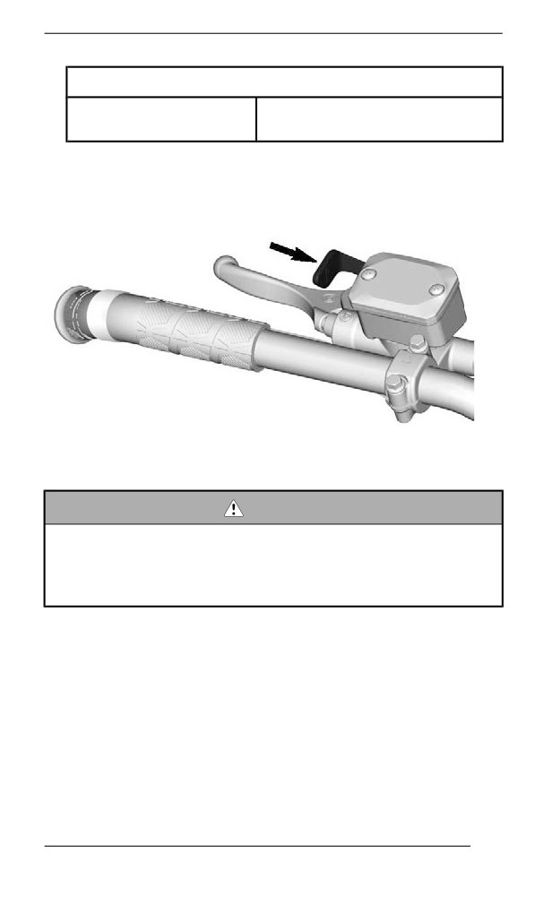
Parking Brake Lever
Parking brake lever is located on the LH side of handlebar.
TYPICAL
Parking brake should be used whenever snowmobile is parked.
WARNING
Make sure parking brake is fully disengaged before operating
the snowmobile. When you ride the vehicle, brake pads that are
caused to drag by a continuous pressure on the lever may
cause damage to the brake system and cause loss of braking
capacity and/or fire.
To Engage Parking Brake
Apply and hold brake, then lock brake lever using the parking brake
lever as shown.
143
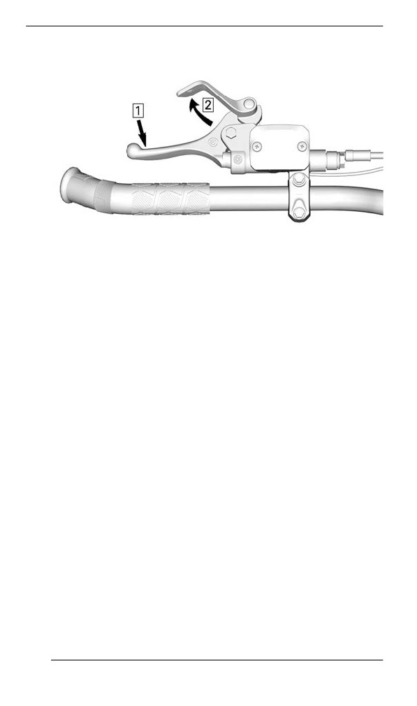
PRIMARY CONTROLS
TYPICAL — ENGAGE MECHANISM
1. Apply and hold brake
2. Lock brake lever using parking brake lever
To Release Parking Brake
Squeeze brake lever. Parking brake lever will automatically return to
its original position. Always release parking brake before riding.
144
PRIMARY CONTROLS
Engine Cut-off Swiitch
D.E.S.S.
145
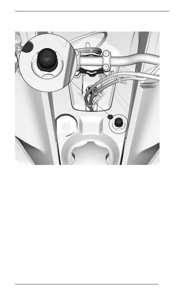
PRIMARY CONTROLS
MECHANICAL SWITCH
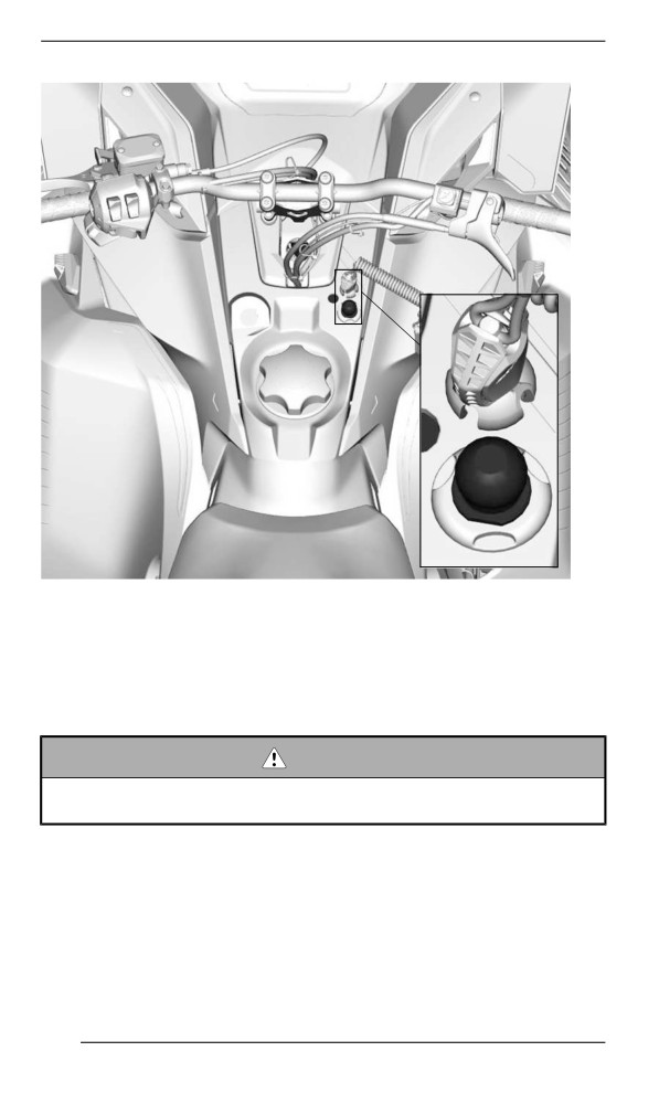
The engine cut-off switch (tether cord) is located on the console.
The tether cord cap must be securely snapped on the engine cut-off
switch to allow vehicle operation.
Pulling the tether cord cap from the switch shuts the engine off.
WARNING
Always attach the tether cord eyelet to clothing before starting
the engine.
D.E.S.S. (Digitally Encoded Security System)
The tether cord cap has an integrated D.E.S.S. key to provide you and
your snowmobile with the equivalent security of a conventional lock
key.
The D.E.S.S. key contains an electronic chip which features a unique
permanently memorized digital code.
146
PRIMARY CONTROLS
Your authorized BRP snowmobile dealer has programed the D.E.S.S.
of your snowmobile to recognize the D. E. S. S. key in the tether cord
cap to allow vehicle operation.
If another tether cord is used without programming the D.E.S.S., the
engine will start but will not reach drive pulley engagement speed to
move vehicle.
Make sure the tether cord cap is free of dirt or snow.
D.E.S.S. Flexibility
The D.E.S.S. of your snowmobile can be programmed by your author-
ized BRP snowmobile dealer to accept up to 8 different keys.
We recommend the purchase of additional tether cords from your au-
thorized BRP snowmobile dealer. If you have more than one D.E.S.S.
equipped BRP snowmobile, each can be programmed by your author-
ized BRP snowmobile dealer to accept the other vehicles D. E. S. S.
keys.
147
SECONDARY CONTROLS
Some features may not apply to your model or could be optional.
Vehicle safety labels are not shown on illustrations. For information on
vehicle safety labels, refer to Vehicle Safety Labels.
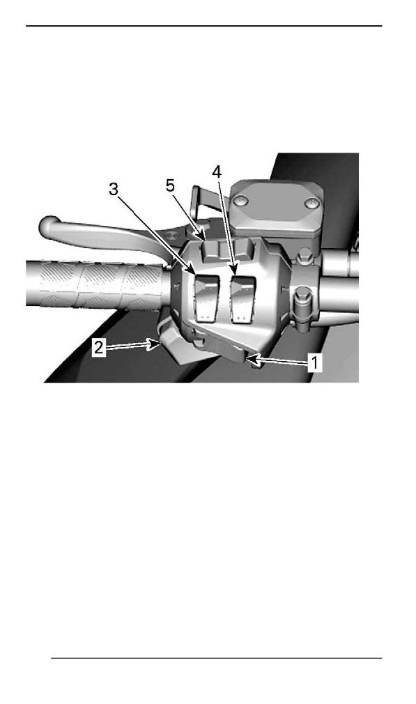
Handllebar Mulltiifunction Switch
Multifunction switch is located on the LH side of handlebar.
TYPICAL - MODELS WITHOUT THE LARGE PANORAMIC 7.8"
WIDE LCD DISPLAY
1. Start/Electronic Reverse button
2. Headlights dimmer switch
3. Heated grips switch
4. Heated throttle lever switch
5. Mode/set button (If equipped)
148
SECONDARY CONTROLS
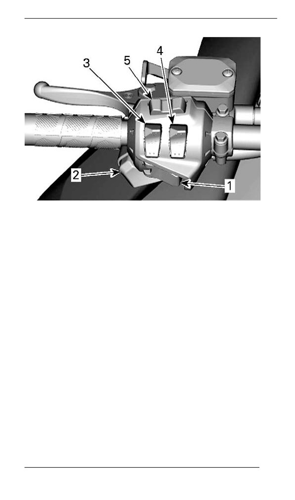
MODELS WITH THE LARGE PANORAMIC 7.8" WIDE LCD
DISPLAY
1. Start/Electronic Reverse button
2. Headlights dimmer switch
3. Heated grips switch
4. Heated throttle lever switch
5. Audio Control and Phone call control
Start / Electronic Reverse Button
Press to start engine. Refer to Engine Starting Procedure in Basic
Procedures.
Once engine is started, press to engage the electronic reverse. Refer
to Shifting in Reverse in Basic Procedures for procedure.
Headlights Dimmer Button
Press to select HI or LOW beam. Lights are automatically ON when
the engine is running.
Heated Grips Switch
NOTE:
Under 2000 RPM, heated grips will be limited at 50%.
149
SECONDARY CONTROLS
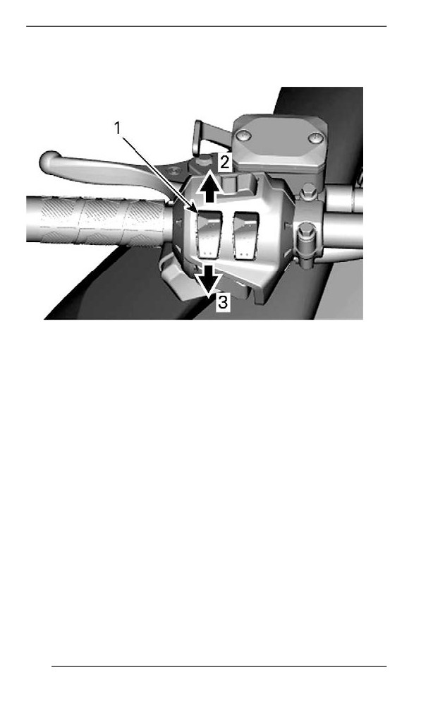
Depress switch as required to select heating intensity to keep your
hands at a comfortable temperature.
VARIABLE INTENSITY
1. Heated grip switch
2. Increase heat
3. Decrease heat
The heating intensity is displayed via the digital display.
150
SECONDARY CONTROLS
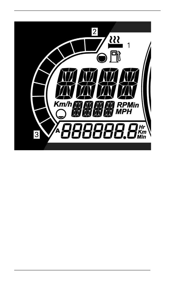
MODELS WITHOUT THE LARGE PANORAMIC 7.8" WIDE LCD
DISPLAY SHOWN
1. Heated grip icon
2. More heat
3. Less heat
There are ten intensity settings. When released, display will return to
fuel level.
Heated grips will be in OFF position when there are no bars displayed
on the gauge.
NOTE:
For models with the Large Panoramic 7.8" Wide LCD Display, refer to
Large Panoramic 7.8” Wide LCD Display section.
151
SECONDARY CONTROLS
Heated Throttle Lever Switch
NOTE:
Under 2000 RPM, heated throttle lever will be limited at 50%.
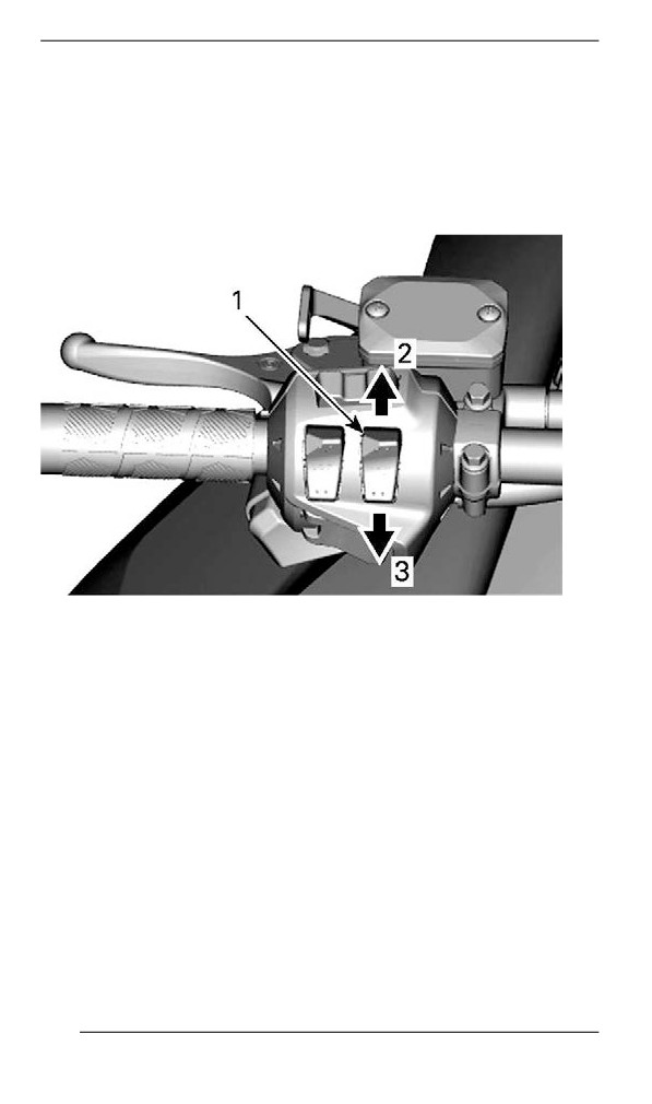
Depress switch as required to select heating intensity to keep your
thumb at a comfortable temperature.
VARIABLE INTENSITY
1. Heated throttle lever switch
2. Increase heat
3. Decrease heat
NOTE:
There are ten intensity settings. When released, display will return to
engine temperature.
152
SECONDARY CONTROLS
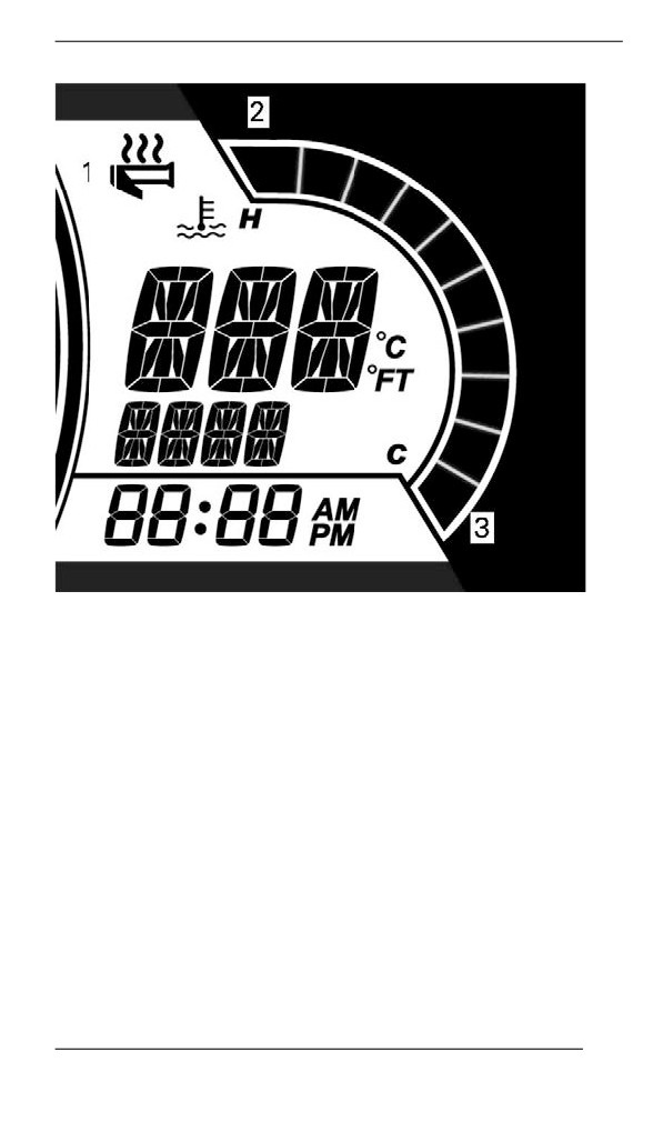
MODELS WITHOUT THE LARGE PANORAMIC 7.8" WIDE LCD
DISPLAY SHOWN
1. Heated grip icon
2. More heat
3. Less heat
Heated throttle lever will be in OFF position when there are no bars
displayed on the gauge.
NOTE:
For models with the Large Panoramic 7.8" Wide LCD Display, refer to
Large Panoramic 7.8” Wide LCD Display section.
Menu/Set Button
Models without the Large Panoramic 7.8" Wide LCD Display
This button is used to manage the information displayed on the multi-
function gauge.
153
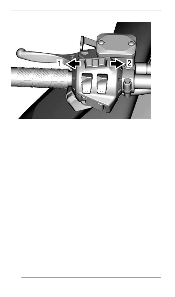
SECONDARY CONTROLS
MENU/SET BUTTON
1. Menu function
2. SET function
Refer to Gauge for complete information.
Audio Volume Control (if equipped)
Models with the Large Panoramic 7.8" Wide LCD Display
This button is used to manage the information displayed on the multi-
function gauge or answer/cancel a phone call.
154
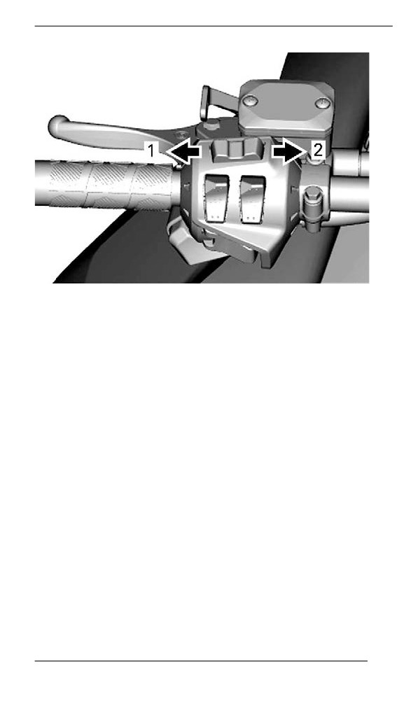
SECONDARY CONTROLS
1. Volume DOWN/Cancelling a call
2. Volume UP/Answering a call
Refer to Large Panoramic 7.8” Wide LCD Display section for complete
information.
155
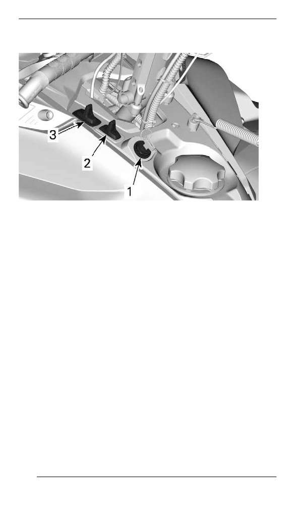
SECONDARY CONTROLS
Console Swiitches (iif equiipped)
TYPICAL
1. Start/Electronic reverse switch
2. Heated grips switch
3. Headlights dimmer switch
Start/ Electronic Reverse Switch
Models with 600 EFI Engines
156
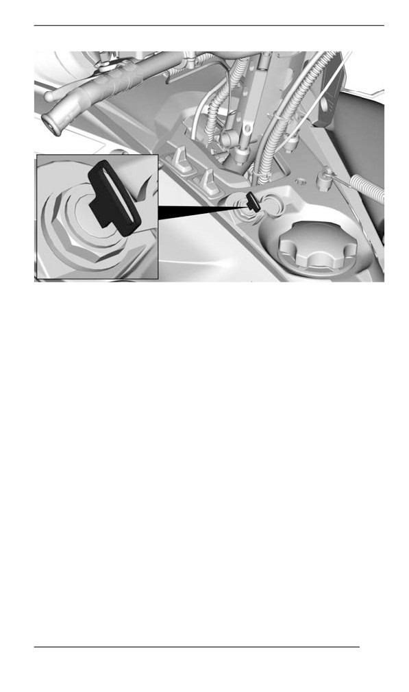
SECONDARY CONTROLS
TYPICAL
Turn the ignition key to start the engine. Refer to Engine Starting Pro-
cedure in basic procedures.
Once engine is started, turn the key to engage the electronic reverse.
Refer to Reverse (RER) in basic procedures.
Heated Grips and Heated Throttle Lever Switch
NOTE:
Under 2000 RPM, heated grips will be limited at 50%.
The switch on the console controls simultaneously the handlebar grips
and the throttle lever heat intensity.
The balance between the temperature of the throttle lever and the
grips can be adjusted.
Depress switch as required to select heating intensity to keep your
hands at a comfortable temperature.
157
SECONDARY CONTROLS
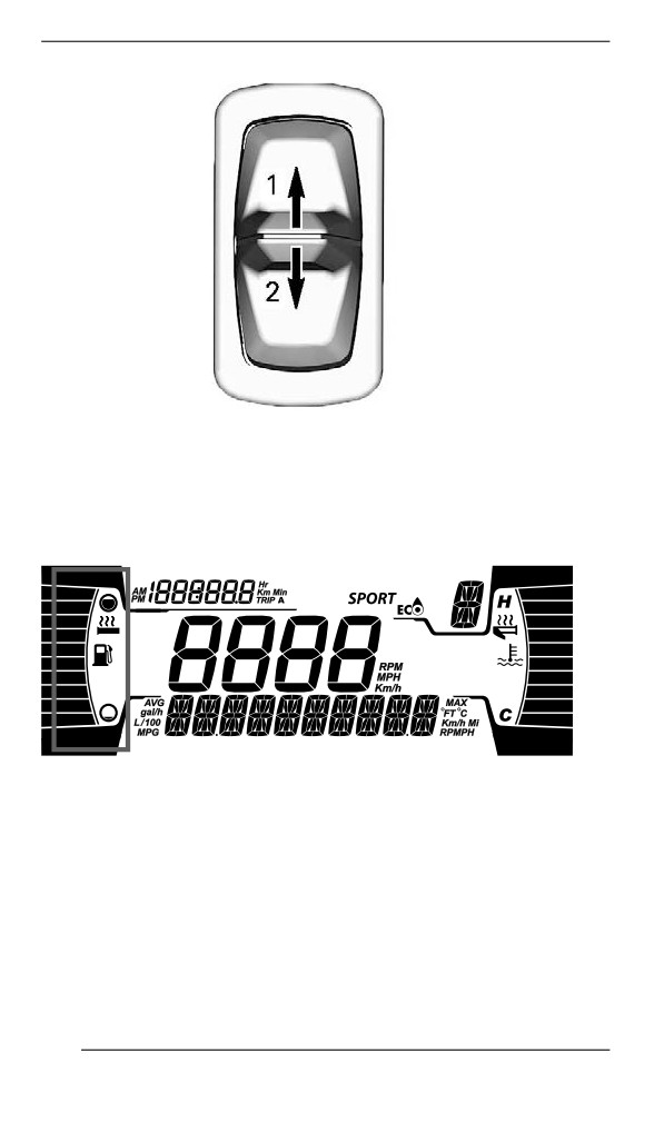
SWITCH ON CONSOLE
1. Increase heat
2. Decrease heat
The heating intensity is displayed via the digital display.
HEATED GRIPS DISPLAY
158
SECONDARY CONTROLS
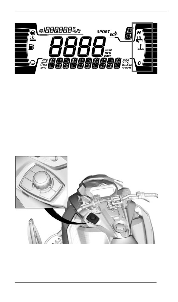
HEATED THROTTLE LEVER DISPLAY
Heated grips and throttle lever will be OFF when there are no bars dis-
played on the gauge.
When the switch is released, display will return to fuel level and engine
temperature.
Headlights Dimmer Button
Press to select HI or LOW beam. Lights are automatically ON when
the engine is running.
Rotary Controll (if equiipped)
The rotary control is located on the left side of the console.
TYPICAL
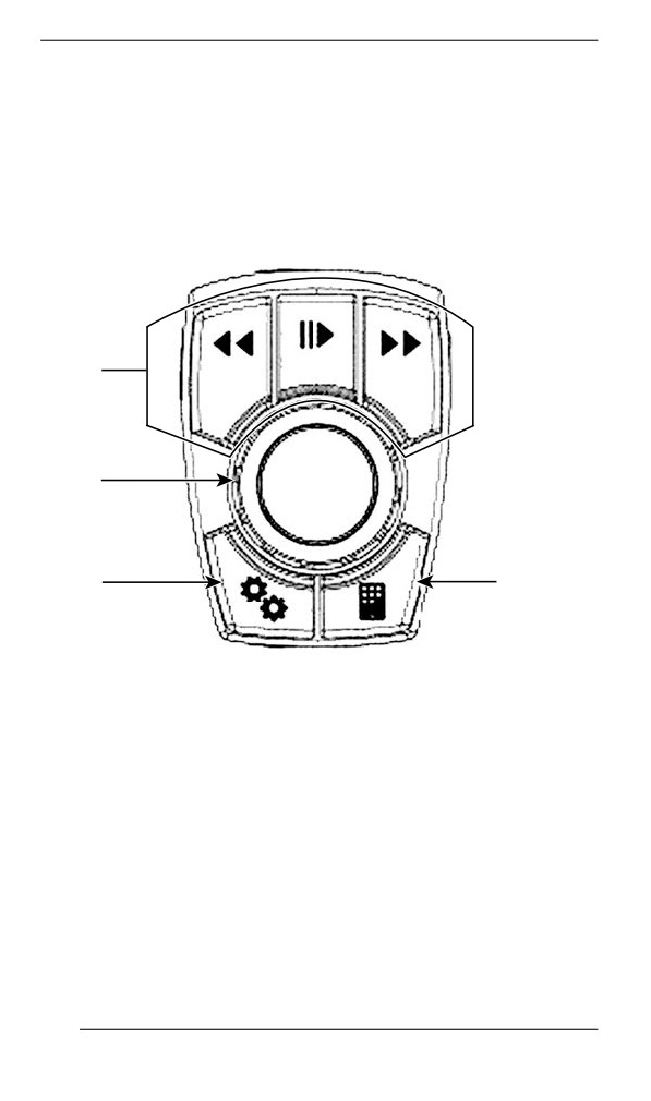
It is used to navigate into the LCD display and control the audio
system.
159
SECONDARY CONTROLS
- Seek/Play/Pause buttons allow to control volume and music lis-
tened in the helmet audio system.
- The center knob can be used to navigate inside menu or select
and set settings.
- Specific vehicle data button allow to see engine temperature, and
battery voltage. It will also shown air suspension adjustment (if
equipped)
- BRP Connect button: quick access to already downloaded APPS.
1
2
3
4
1. Audio control
2. Center knob
3. Vehicle data button
4. BRP Connect
When audio source is selected, the Preset/Seek buttons work as
follow:
- Short press: Previous or Next Preset
- Long press: Seek - up or down
When Bluetooth audio source is selected, the Preset/Seek buttons
work as follow:
- Left: Previous song
- Right: Next song
160
SECONDARY CONTROLS
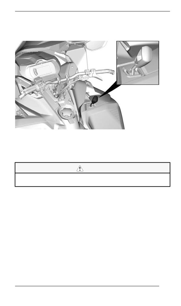
Gearshift Lever
Model equipped with Hi/Lo Gearbox
Use this lever to select gears. The gearbox has two forward gears and
a neutral.
Shifting from one position to another is possible at speeds lower than
30 km/h (19 MPH)
CAUTION
Shifting at a speed faster than 30 km/h (19 MPH) may cause
serious damage to the gearbox.
Neutral
The neutral position disengages the gearbox forward gears.
NOTE: The reverse gear still can be activated.
High Range (Forward)
This position selects the high speed range of the gearbox. It is the nor-
mal driving speed range. It allows the vehicle to reach its maximum
speed.
Low Range (Forward)
This position selects the low speed range of the gearbox. It allows the
vehicle to move slowly with maximum torque.
161
SECONDARY CONTROLS
NOTICE
Use the low speed range to pull a cargo carrier, carry heavy
cargo, go over obstacles or drive uphill and downhill.
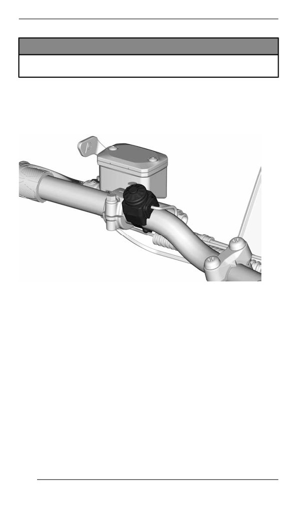
Horn Button (if equiipped)
For vehicles sold in Finland
Press on the horn button to activate the horn.
TYPICAL
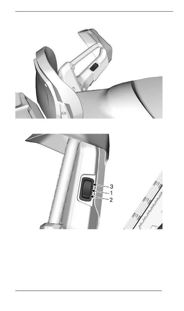
Passenger Heated Griip Switch (if equiipped)
The switch is located on the LH passenger handhold.
162
SECONDARY CONTROLS
Adjust heating intensity as shown.
1. Off
2. Warm
3. Hot
163
BODY AND SEAT
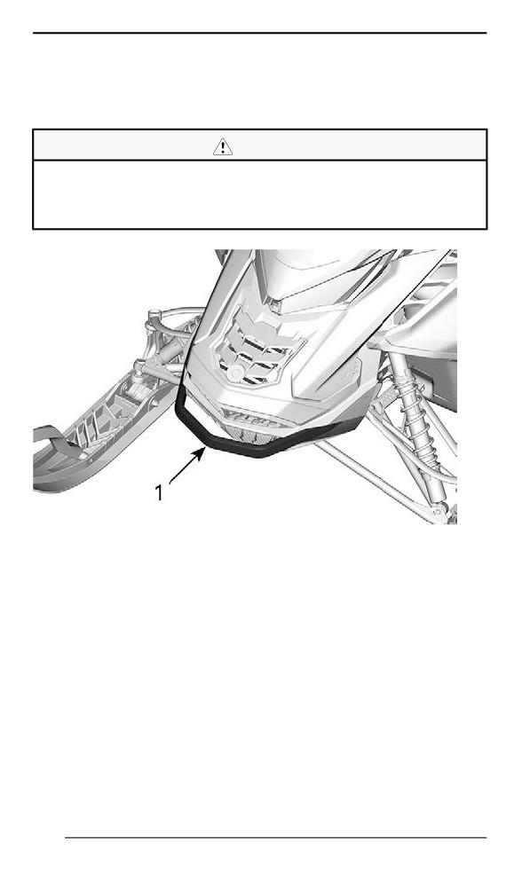
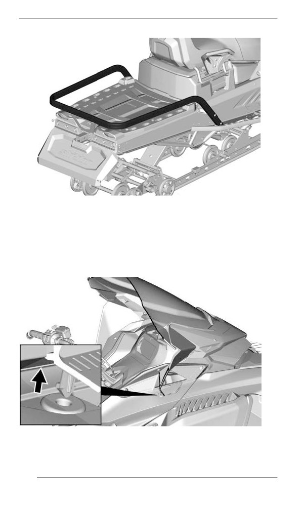
Front and Rear Bumpers
To be used whenever snowmobile requires manual lifting.
CAUTION
Beware of injuries by using proper lifting techniques, notably
using your legs force. Do not attempt to lift the rear of vehicle if
it is above your limits. Use appropriate lifting device or have as-
sistance to share lifting stress if possible.
1. Front bumper
164
BODY AND SEAT
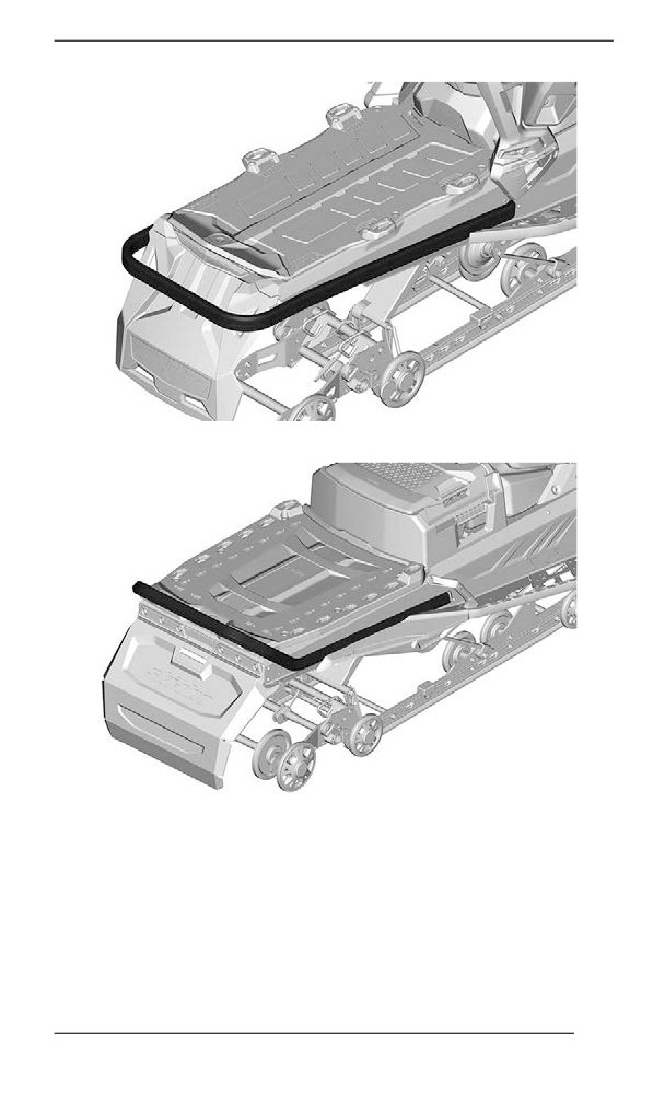
TYPICAL - STD BUMPER
STD BUMPER — 20 INCHES TUNNEL
165
BODY AND SEAT
CARGO - HEAVY DUTY BUMPER — 20 AND 24 INCHES
TUNNEL
Windshiield
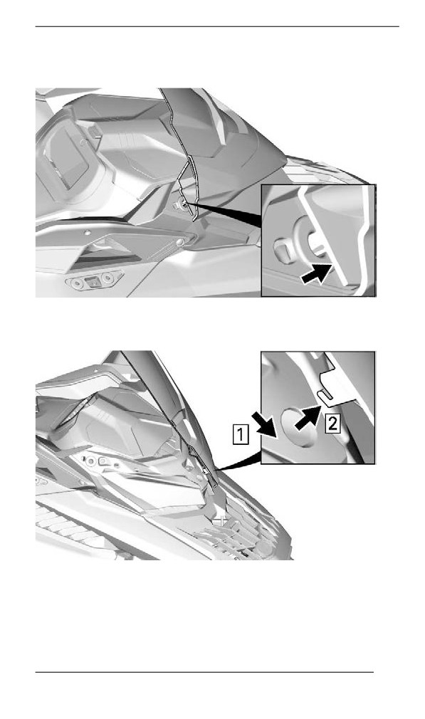
Removing the Windshield
1. Pull off the deflector pins off the grommets, if applicable.
TYPICAL — WITH SIDE DEFLECTORS
2. Place hands on each sides of the windshield.
166
BODY AND SEAT
3. Pull the windshield up until both side pins come out of their rubber
grommets.
TYPICAL
4. Disengage the center pin or tab, if applicable.
TYPICAL — CENTER TAB - WITH SIDE DEFLECTORS
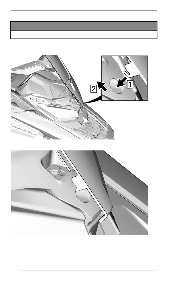
Installing the Windshield
1. Lubricate the grommets using soapsuds, if required.
167
BODY AND SEAT
NOTICE
Do not lubricate grommets with any type of grease.
2. Insert center pin or tab in headlamp module hole.
TYPICAL - CENTER TAB - WITH SIDE DEFLECTORS
TYPICAL
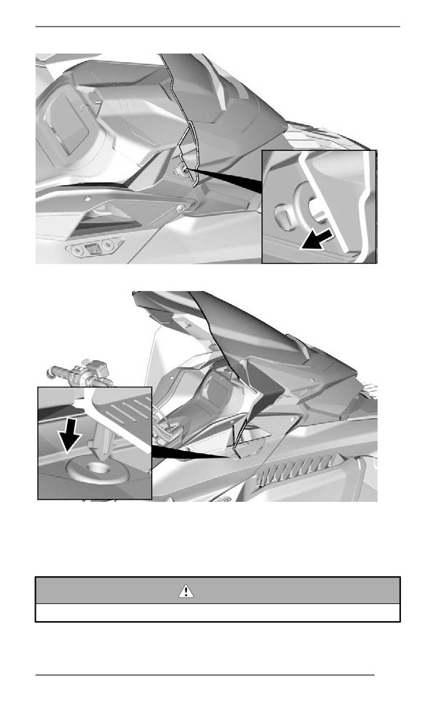
3. Secure windshield by inserting the windshield pins into the
grommets.
168
BODY AND SEAT
TYPICAL
TYPICAL — WITH SIDE DEFLECTORS
Adjustablle Mirrors (if equiipped)
Each mirror can be adjusted to suit operator's preference.
WARNING
Adjust with vehicle at rest in a safe place.
169
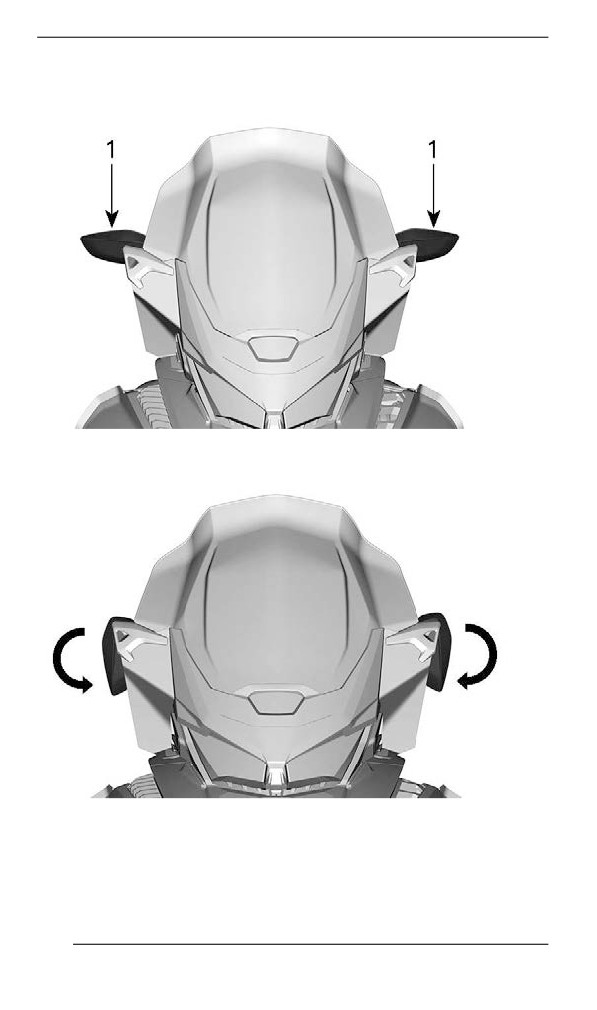
BODY AND SEAT
When installing a cover, the mirrors can be tilted downward to ease
installation.
TYPICAL
1. Mirrors
TYPICAL
170
BODY AND SEAT
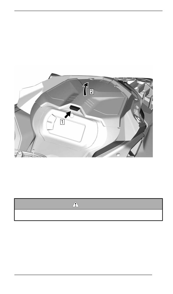
Front Storage Compartment
A storage compartment is located at the front of the vehicle, above the
gauge.
The Operator's Guide and the emergency starter rope are in the front
storage compartment.
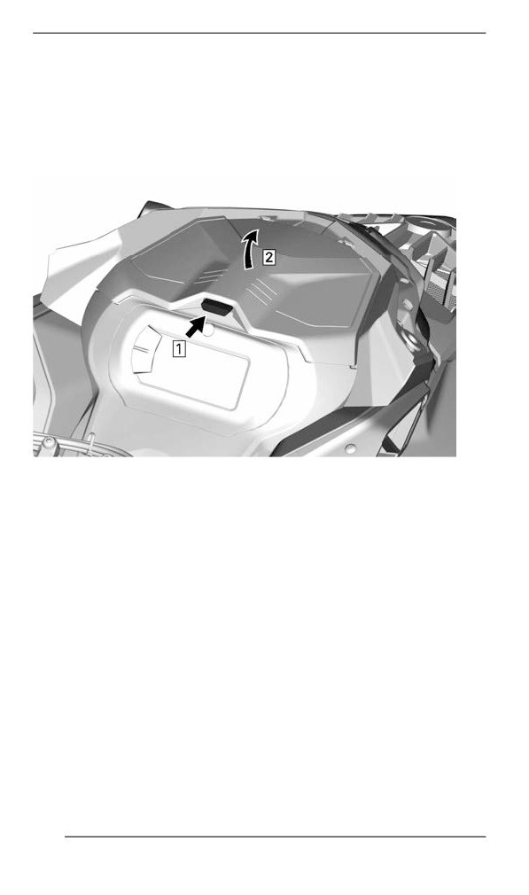
To open, push the button and lift the cover.
TYPICAL
NOTE:
When closing, make sure cover is secured properly. You will hear a
"click".
Siide Panels
WARNING
Never operate engine with side panels opened or removed from
vehicle.
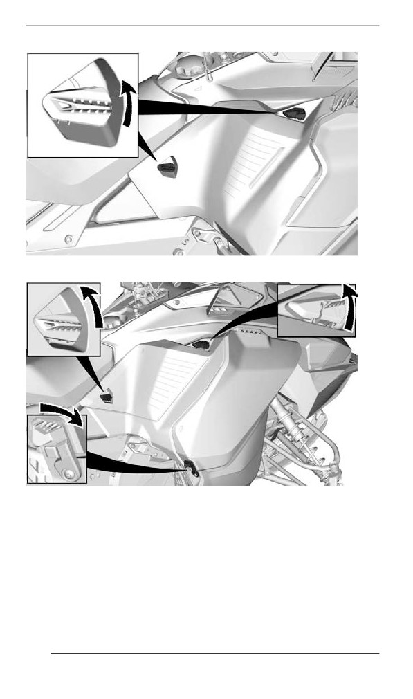
Removing the Side Panels
1. Unlock all latches, then open panel.
171
BODY AND SEAT
TYPICAL — 2 LATCHES
TYPICAL — 3 LATCHES
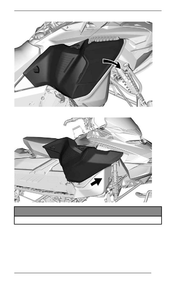
2. Pivot side panel around lower edge.
172
BODY AND SEAT
3. Slide the panel hinge off the bottom pan.
NOTICE
Make sure to place panel in a safe place to avoid scratching.
Installing the Side Panels
The installation is the reverse of the removal procedure.
173
BODY AND SEAT
Upper Body Module
Removing the Upper Body Module
1. Remove the windshield. Refer to Removing the Windshield in Body
and Seat subsection.
2. Open the storage compartment.
TYPICAL
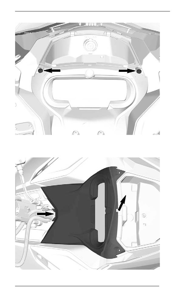
3. Remove the gauge support retaining screws.
174
BODY AND SEAT
TYPICAL
4. Lift the front of the gauge support, then slide it forward to remove it.
175
BODY AND SEAT
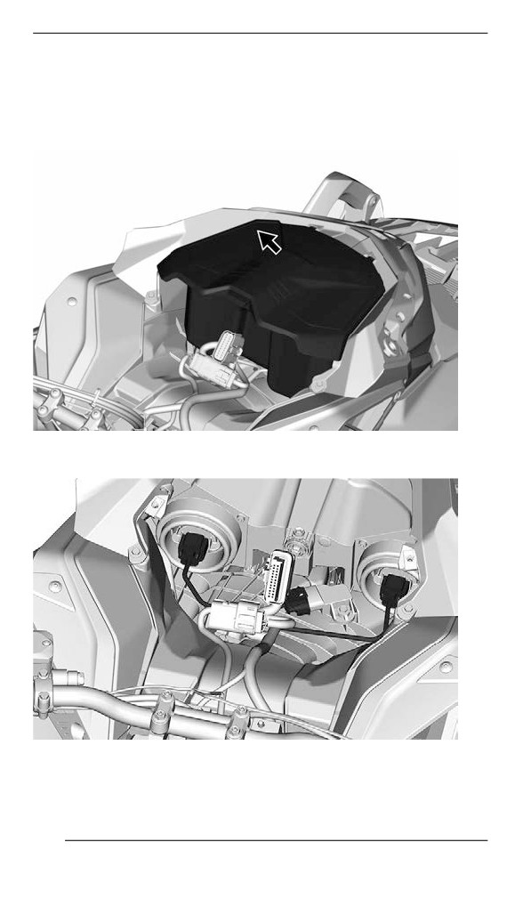
5. Disconnect the gauge connector and remove the support.
6. Lift the storage compartment and disconnect the 12V power outlet
connectors, if equipped, before removing the storage
compartment.
7. Disconnect the headlight and the MAPTS (2-stroke) connectors.
TYPICAL
8. Remove both side panels. Refer to Side Panels in this section.
176
BODY AND SEAT
9. Loosen the air intake duct clamp.
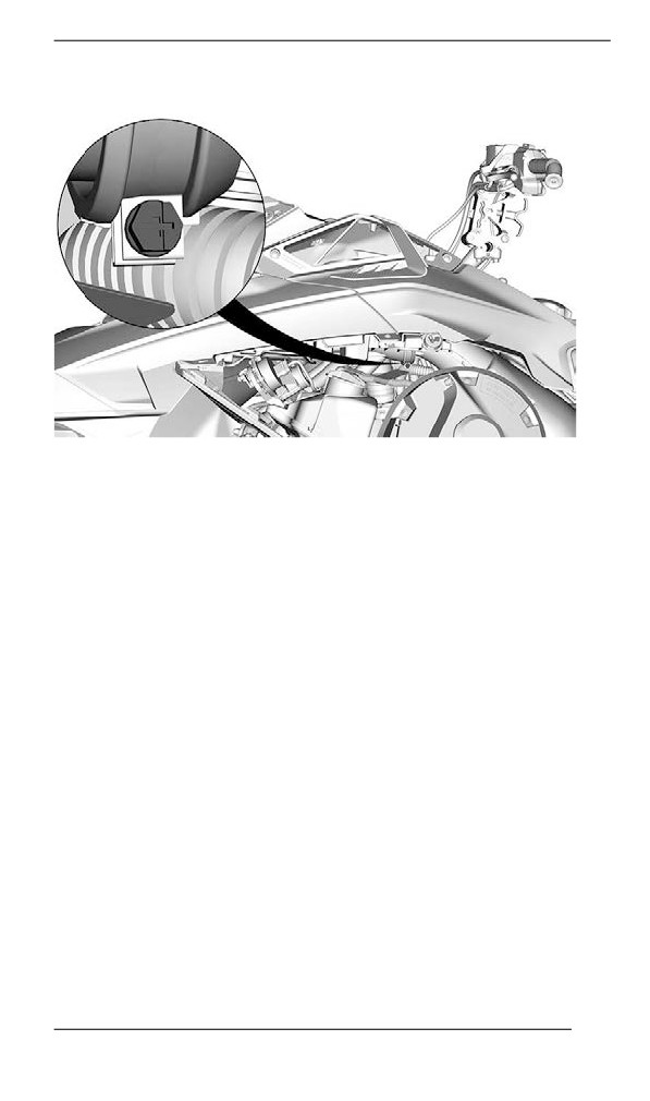
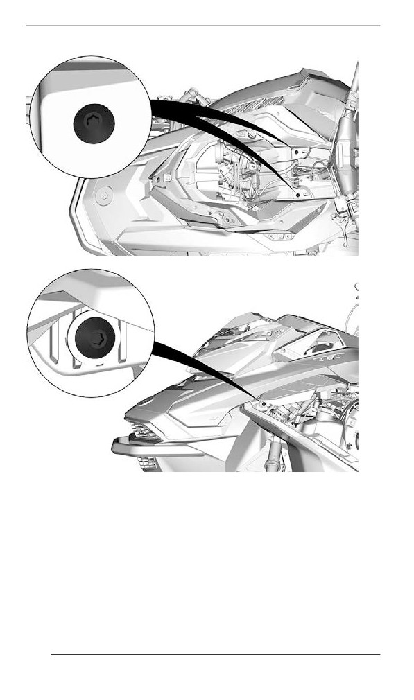
10. Remove the upper body module retaining screws on both sides.
177
BODY AND SEAT
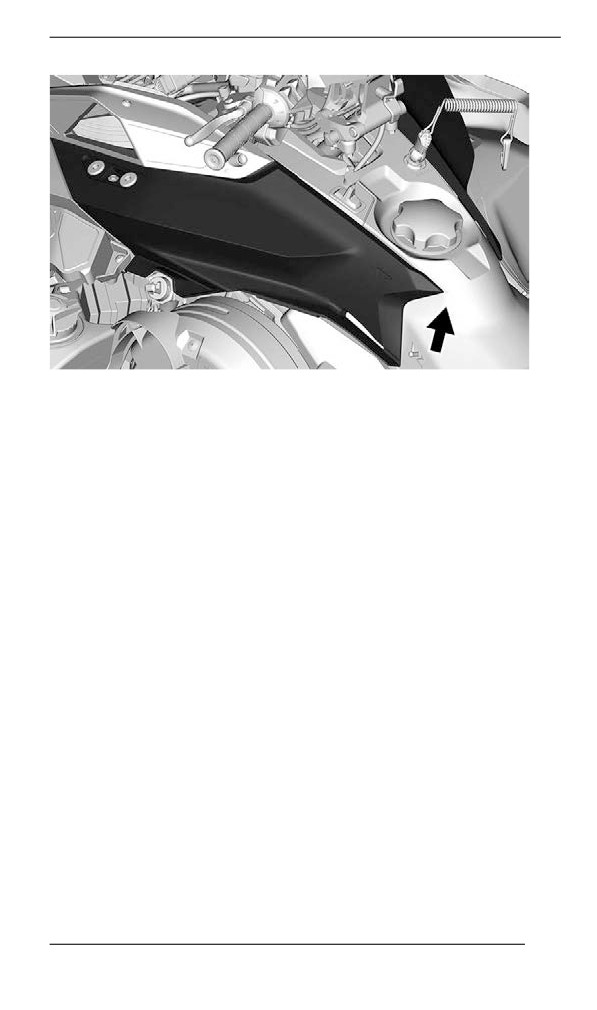
11. Lift the rear end of both lateral hood until their tabs come out of the
rear console.
178
BODY AND SEAT
12. Remove the upper body module.
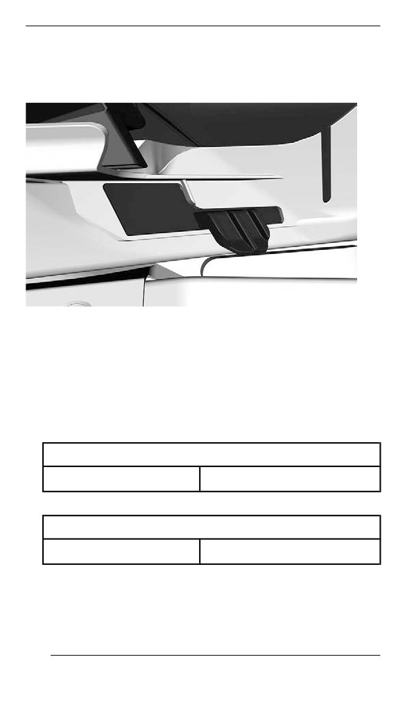
1. Grab the upper body module in the gauge support section.
2. Pull the module forward.
3. Remove the module from the vehicle.
179
BODY AND SEAT
Installing the Upper Body Module
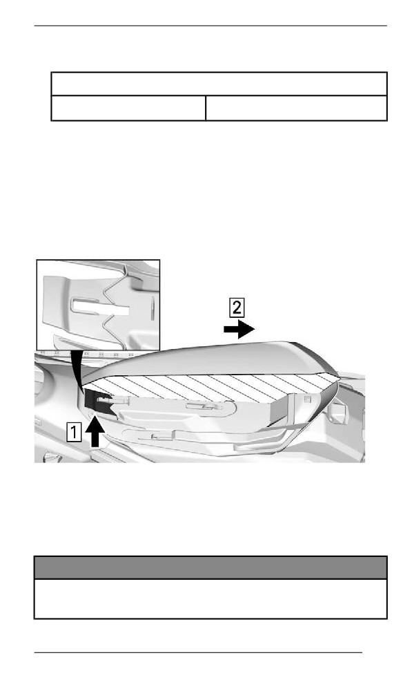
1. At front, insert the upper body module tabs into the bottom pan
openings.
FRONT HOOD TAB
2. Lower the rear end of the upper body module.
3. Insert the rear end hooks of the upper body module into the slots in
the console.
NOTE:
Make sure the air intake duct is positioned properly connected.
4. Tighten air intake duct clamp.
TIGHTENING TORQUE
Intake duct clamp
1.0 ± 0.2 Nm (9 ± 2 lbf-in)
5. On both sides, install the upper body module retaining screws.
TIGHTENING TORQUE
Upper body screws
1.8 ± 0.2 Nm (16 ± 2 lbf-in)
6. Connect the manifold air pressure and temperature sensor
(MAPTS) connector (2-stroke engine).
7. Connect the headlight connectors.
8. Install the storage compartment but leave the cover open.
180
BODY AND SEAT
9. Install gauge, secure with the screws.
TIGHTENING TORQUE
Gauge support screws
2.3 ± 0.2 Nm (20 ± 2 lbf-in)
Seat
400 mm (16 in.) Tunnel Width
Removing the Seat (tab llock)
From between the fuel tank and the seat front end, pull the locking tab
upwards.
Slide the seat backwards while holding the tab up.
TYPICAL — CROSSCUT VIEW OF SEAT FOAM
1. Pull upwards
2. Slide backwards
Installliing the Seat (tab llock)
NOTICE
Riding the vehicle with any objects between the seat and the
fuel tank could damage the fuel tank. NEVER place any objects
between seat and fuel tank.
181
BODY AND SEAT
Place seat over the hooks, then slide it forward until the tab locks over
the front hook.
WARNING
Make sure seat is securely latched before riding.
Removiing the Seat (balll stud llock)
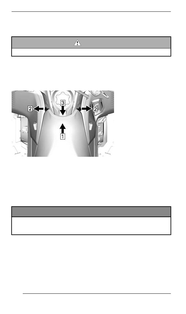
While pushing in the center of the seat towards front, pull on both
sides. Insert hand between seat and body to lift up and backward to
unlock.
1. Push
2. Pull
3. Lift up and backward to unlock seat
Slide seat rearwards to remove it.
Installling the Seat (balll stud lock)
NOTICE
Riding the vehicle with any objects between the seat and the
fuel tank could damage the fuel tank. NEVER place any objects
between seat and fuel tank.
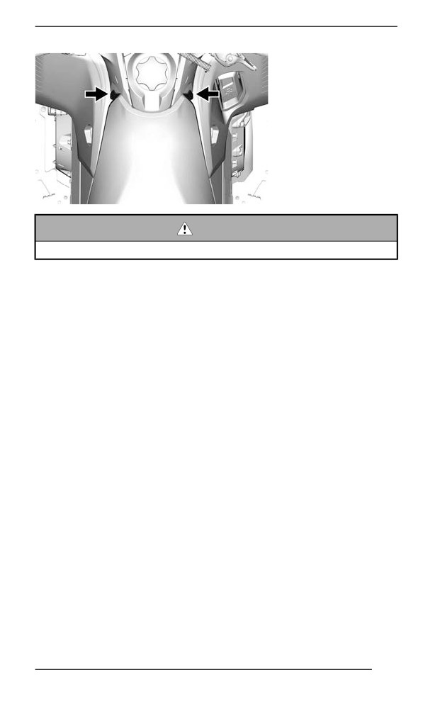
Place seat over the hooks, then slide it forward.
Securely engage both ball studs at front.
182
BODY AND SEAT
WARNING
Make sure seat is securely latched before riding.
183
BODY AND SEAT
Backrest (if equipped)
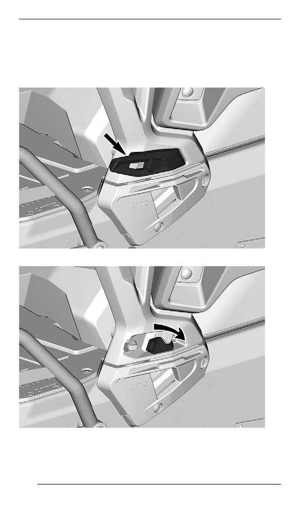
Removiing the Backrest
1. Disengage the LinQ lever cap on both sides.
2. Unlock the LinQ on both sides.
3. Pull the backrest upwards to remove..
184
BODY AND SEAT
Installliing the Backrest
The installation is the reverse of the removal procedure.
Passenger Handhollds (iif equipped)
The passenger handholds provide a strong holding point and comfort
for the passenger on long rides.
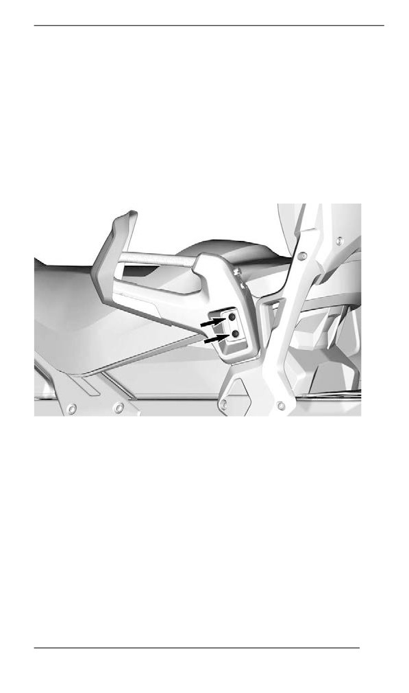
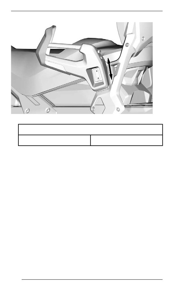
Adjusting the Passenger Handholds
To adjust the handhold height, proceed as follows:
1. Remove the screws.
2. Raise or lower the handhold to suit passenger's comfort.
185
BODY AND SEAT
3. Reinstall the screws. Tighten to specification.
Tightening Torque
Handhold screw
24.5 ± 3.5 Nm (18 ± 3 lbf-ft)
186
BODY AND SEAT
500 and 600 mm (20 and 24 in.) Tunnel Width
Operator’s Seat
Removing the Seat
Release the latch at the back of the seat.
Slide seat rearwards to remove it.
Installliing the Seat
NOTICE
Riding the vehicle with any objects between the seat and the
fuel tank could damage the fuel tank. NEVER place any objects
between seat and fuel tank.
Place seat over the hooks, then slide it forward.
Securely engage the latch.
WARNING
Make sure seat is securely latched before riding.
187
BODY AND SEAT
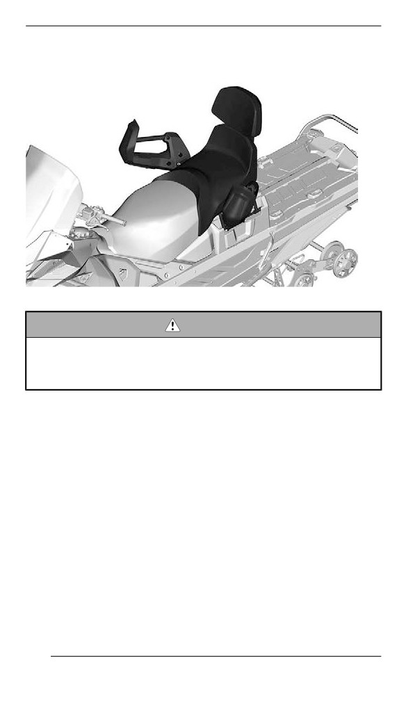
Passenger’s Seat
TYPICAL
WARNING
Any passenger must be able to firmly lay is feet on the footrests
and keep his hands on the handholds at all times when seated.
Respecting those physical criteria is important to ensures that
the passenger is stable and to reduce the risks of ejection.
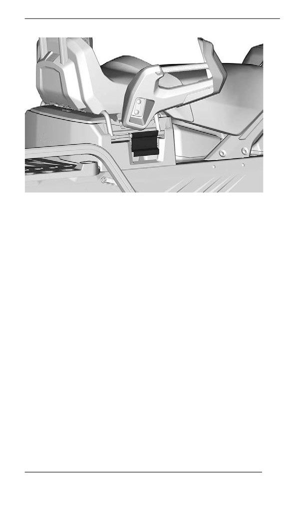
Removiing the Passenger Seat
1. Unlock seat latch on both sides.
188
BODY AND SEAT
TYPICAL
2. Lift the seat to disconnect the electrical connector.
3. Remove passenger seat.
Installliing the Passenger Seat
The installation is the reverse of removal procedure. However, pay at-
tention to the following.
Ensure to reach the second step when latching.
189
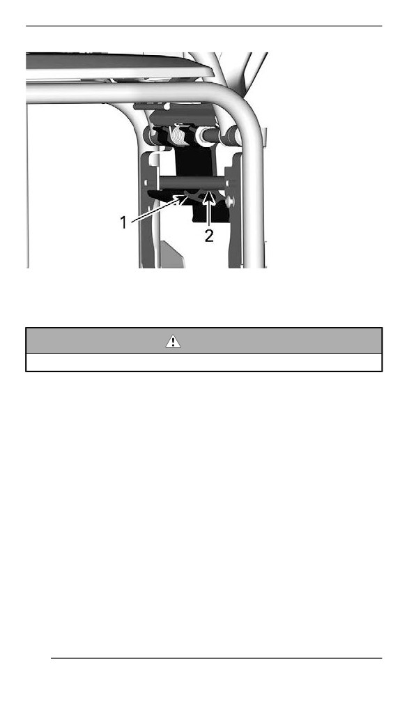
BODY AND SEAT
1. First step
2. Second step
WARNING
Ensure the latch is on the second step before riding.
190
EQUIPMENT
Some features may not apply to your model or could be optional.
Operator''s Guide
The Operator's Guide should be stored in the Front Storage
Compartment.
Mountain Strap
This handlebar strap shall be used only to provide additional pulling
force when snowmobile is stuck in a slanted position. On an excep-
tional basis it can be used at very slow speed only, when standing on
the right running board to bring the vehicle back on its desired path.
When riding, both hands should remain on the handlebar grips to pro-
vide braking capability, as well proper steering and directional control.
Do not use handlebar strap for towing, lifting or side hilling.
WARNING
Do not use while riding at speed. Steering control is highly re-
duced and brake control is not possible.
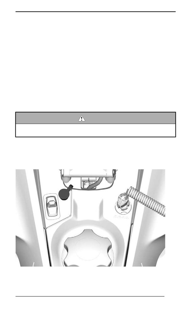
Ellectric Viisor Jack Connector
An electric visor can be connected to the jack connector. A stress re-
lief extension is supplied with the vehicle.
TYPICAL — DRIVER - ELECTRIC VISOR JACK CONNECTOR
LOCATION
191
EQUIPMENT
Drive Belt Guard
Removing the Drive Belt Guard
WARNING
NEVER operate engine:
– Without shields and belt guard securely installed.
– With hood and/or side panels opened or removed.
NEVER attempt to make adjustments to moving parts while en-
gine is running.
NOTE:
Belt guard is purposely made slightly oversize to maintain tension on
its pins and retainers preventing undue noise and vibration. It is impor-
tant that this tension be maintained when reinstalling.
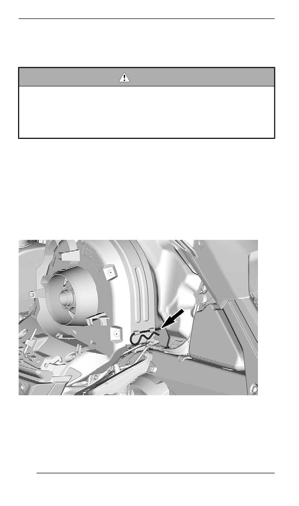
Remove tether cord cap from engine cut-off switch.
Open the LH side panel. See procedure in this section.
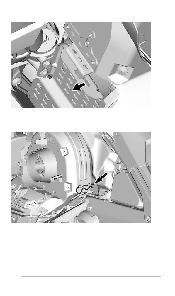
Remove retaining pin.
TYPICAL
Lift rear portion of guard then release from front tab.
192
EQUIPMENT
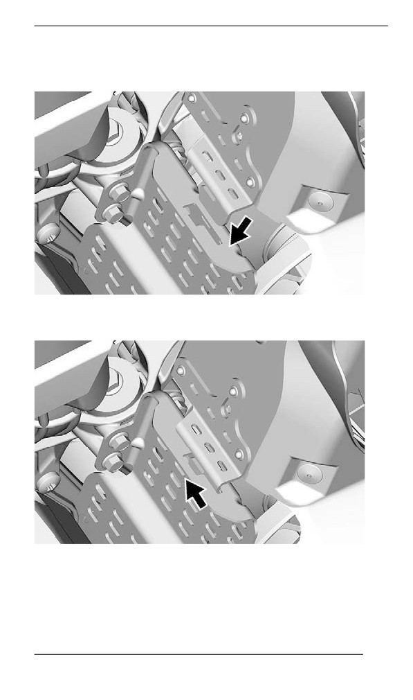
Installing the Drive Belt Guard
Insert belt guard tab in front support slot.
Push drive belt guard toward engine then toward front of vehicle.
193
EQUIPMENT
Position the rear portion of the belt guard over the retainer and secure
it using the retaining pin.
Spare Drive Belt Holder
A spare drive belt can be stored in a holder located on the drive belt
guard.
194
EQUIPMENT
NOTE:
The spare drive belt is not supplied with the snowmobile.
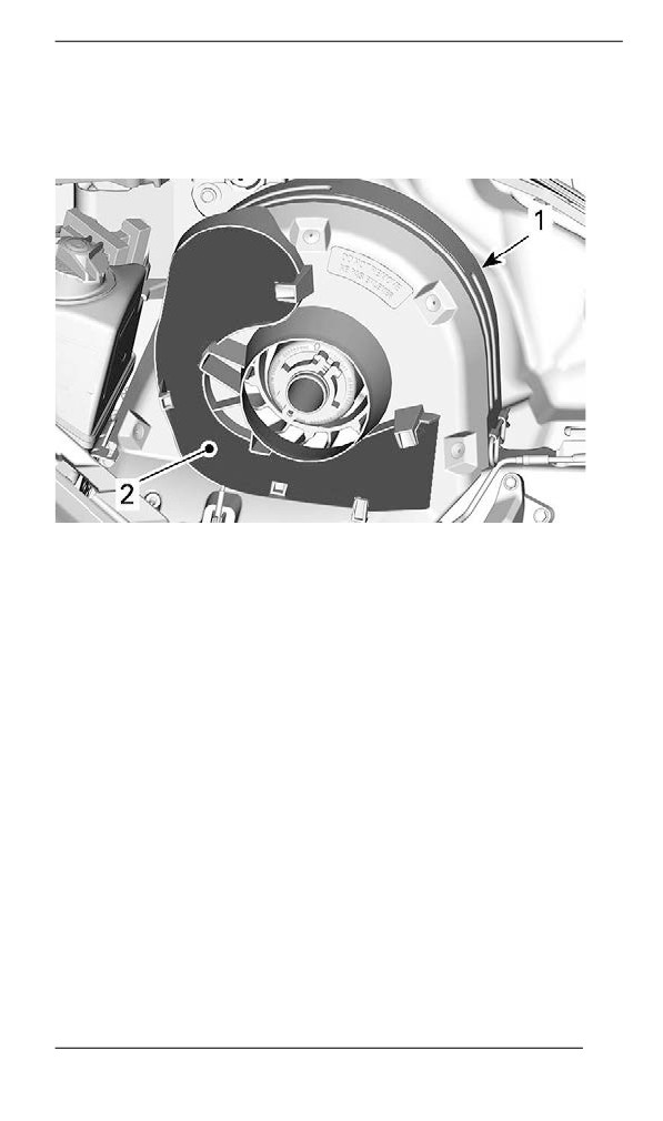
Position spare drive belt into drive belt guard slot.
TYPICAL
1. Drive belt guard
2. Slot
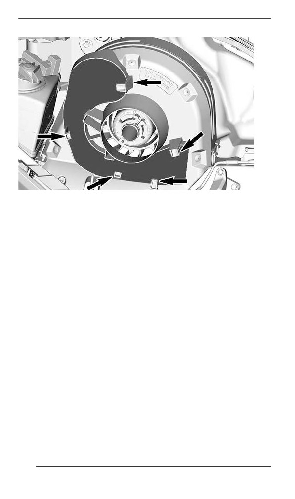
Secure in place by sliding it behind the tabs.
195
EQUIPMENT
TYPICAL
Tools
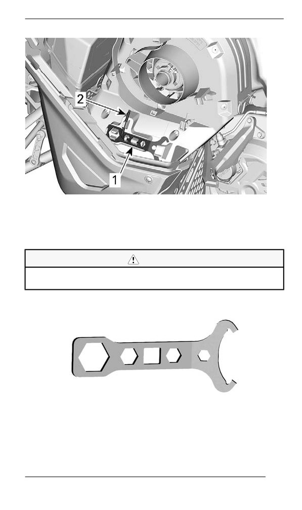
A part of the drive belt guard is designed to hold the tools allowing for
basic maintenance.
The tools are supplied with the vehicle. They should always be in-
stalled in their proper location and orientation.
196
EQUIPMENT
TYPICAL - DRIVE BELT GUARD TOOLS LOCATION
1. Suspension adjustment tool
2. Pulley expander and headlight adjustment tool
Install in the following sequence:
CAUTION
Make sure tools are secured properly. Tools may detach and
cause damage to rotating parts.
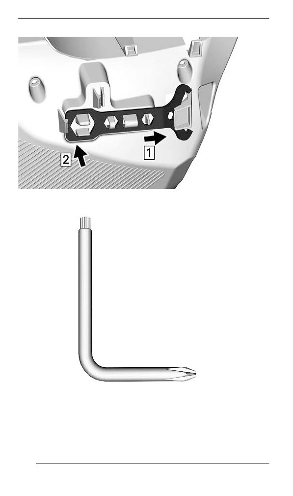
1. Slide the suspension adjustment tool open end under retaining tab.
SUSPENSION ADJUSTMENT TOOL
2. Press the closed end on the retaining tabs.
197
EQUIPMENT
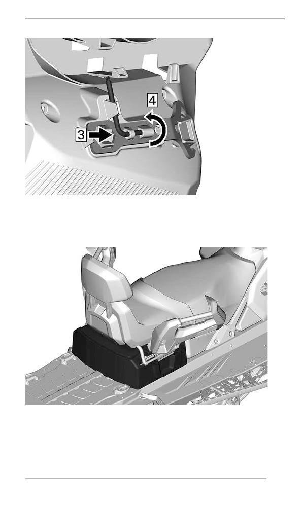
3. Slide the Pulley expander and headlight adjustment tool short end
into hole.
PULLEY EXPANDER AND HEADLIGHT ADJUSTMENT TOOL
4. Rotate and clip long end in place.
198
EQUIPMENT
Rear Storage Compartment
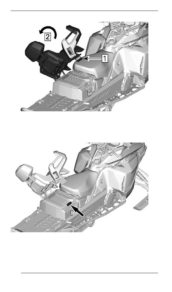
A storage compartment is located at the rear of the seat, above the
battery cover.
TYPICAL
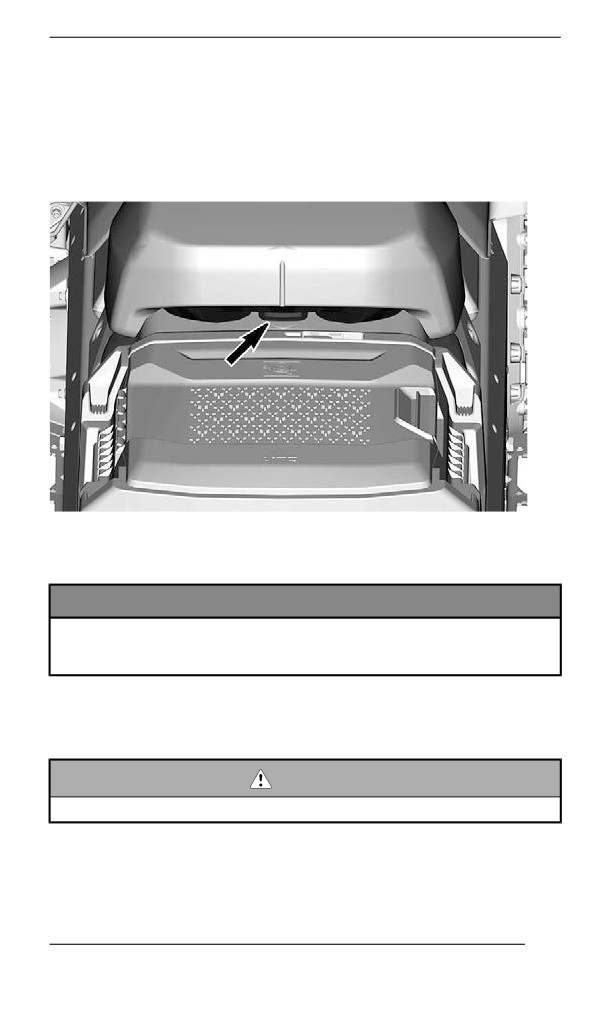
To open, tilt passenger seat.
199
EQUIPMENT
TYPICAL
1. Unlock seat latch
2. Tilt passenger seat
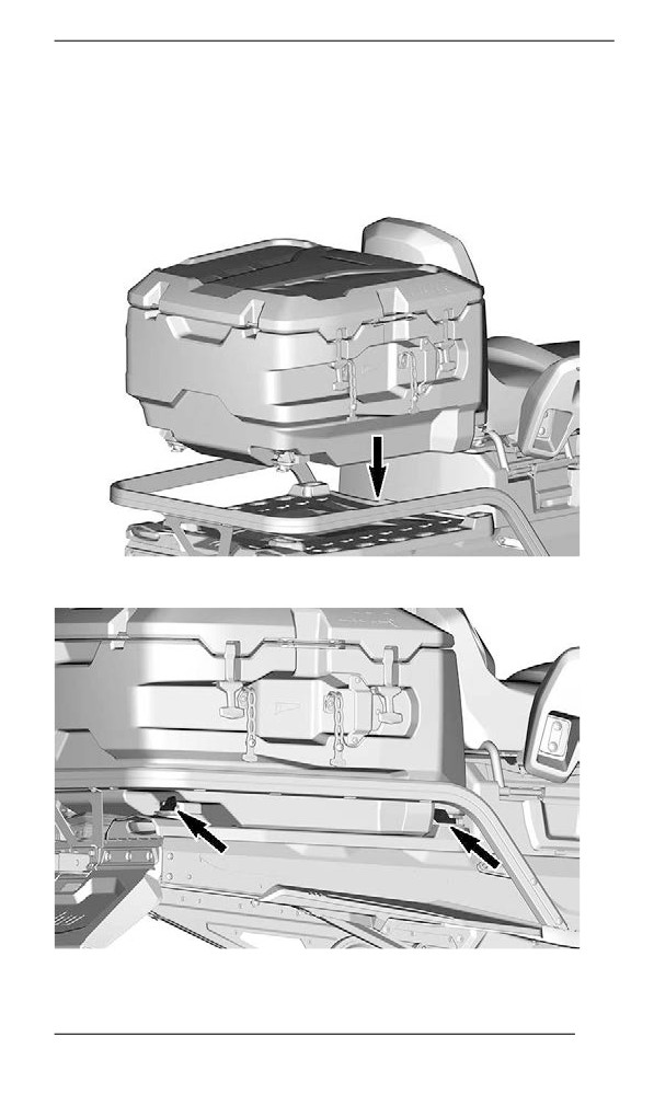
Lift handle.
TYPICAL
200
EQUIPMENT
Cargo Box (if equiipped)
The cargo box can contain up to 22 kg (44 lb) on the cover and a total
of 48 kg (105 lb) (including weight on cover).
The cargo box is secured by LinQ attachment. To Install, lower box in
cargo area.
Turn LinQ levers to lock.
RH SIDE SHOWN - REPEAT ON LH SIDE
201
EQUIPMENT
Hitch (if equiipped)
NOTE:
Refer to decal on vehicle for towing weight capacities.
Hitch type availability depends on applicable models and regions.
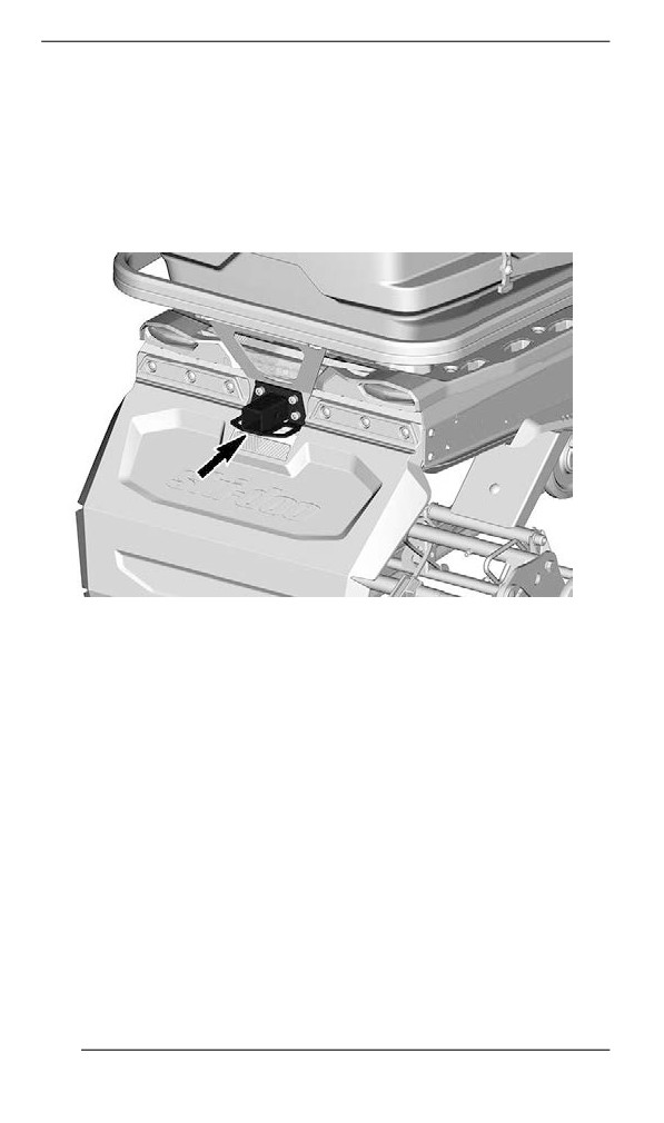
Hitch receiver
Use the hitch in conjunction with a tow bar to tow an accessory.
Tongue Hitch
202
EQUIPMENT
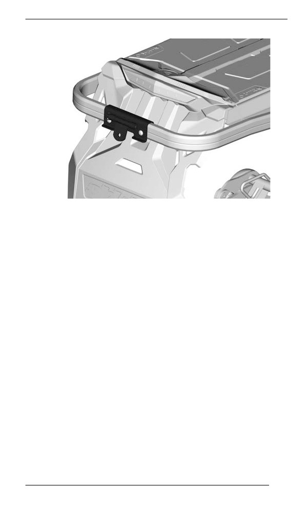
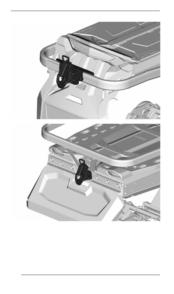
J-Hook Hitch
203
EQUIPMENT
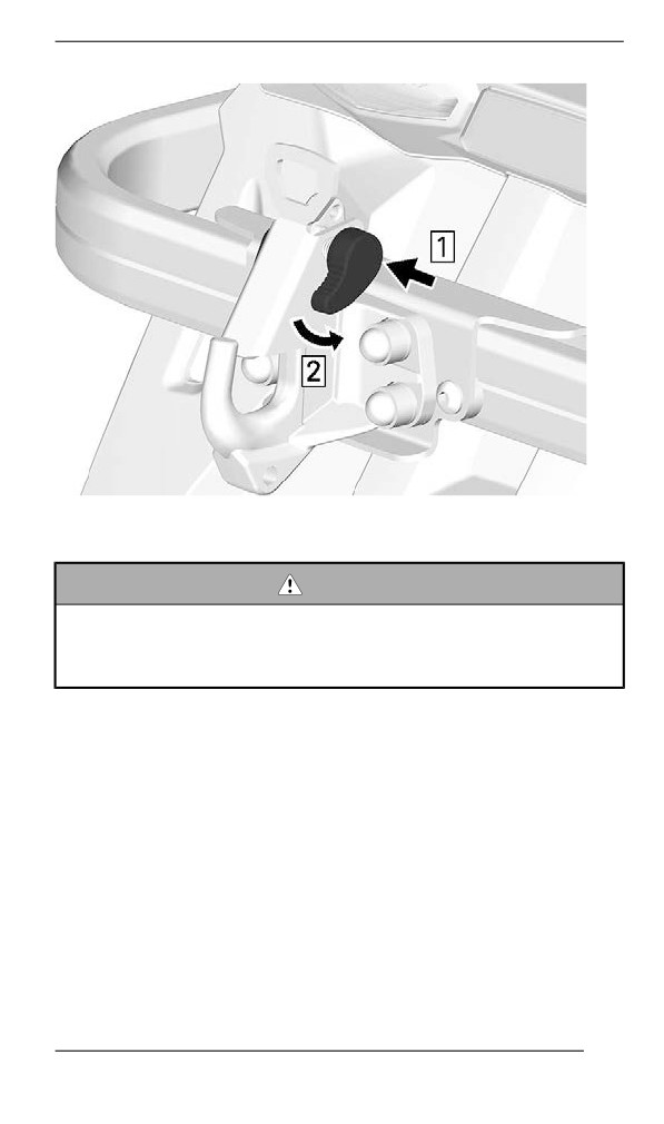
To open the hook, push and turn the handle to retract locking plate.
204
EQUIPMENT
When attaching any accessory, always refer to the manufacturer's
recommendations.
WARNING
Never tow an accessory with a rope. Always use a rigid tow bar.
Using a rope would result in a collision between the object and
the snowmobile and possibly in a tip over in case of a rapid de-
celeration or on a downward slope.
205
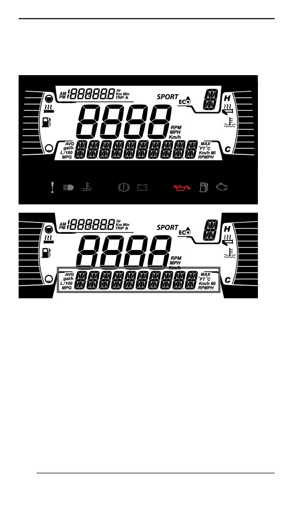
GAUGE – 4.5” DIGITAL DISPLAY
Mulltiifunction Diispllay
Lower Display
May display the following:
- RPM
- Speed
- Engine Temperature
- Fuel Statistics
- Settings
- Messages
- Outside temperature (if equipped)
To change the displayed information, use the gauge LOWER (M) but-
ton, or the Mode button on the handlebar multifunction switch, if
equipped.
The SPEED STAT display shows the maximum and the averaged
speed. Hold LOWER button for 3 seconds to reset.
When the SPEED display is chosen, the RPM is shown in the TRIP
display.
206
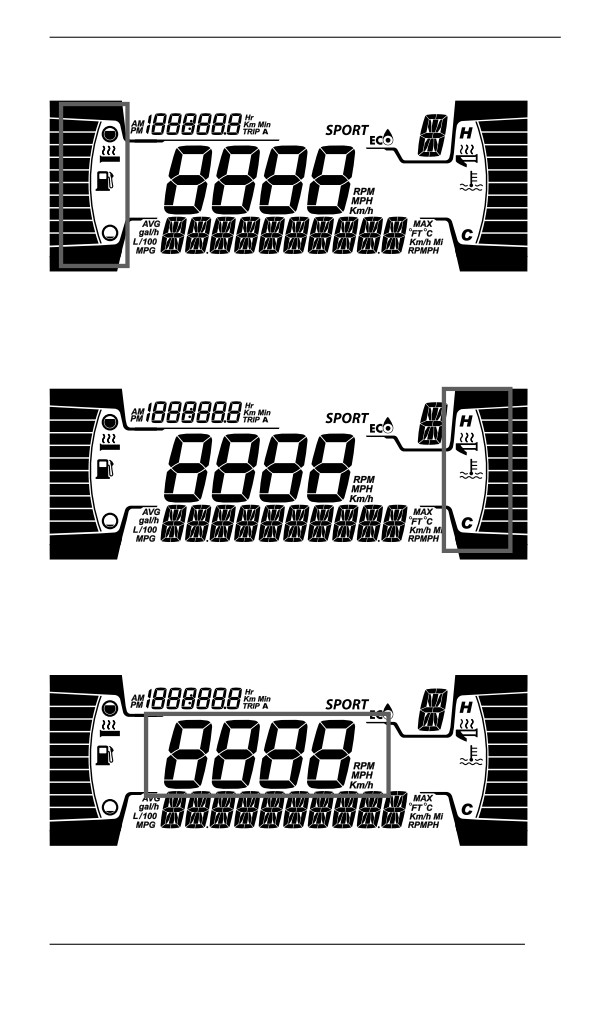
GAUGE - 4.5” DIGITAL DISPLAY
Left Lateral Display
The left lateral display includes:
- Fuel level indicator
- Heated Grip level
Right Lateral Display
The right lateral display includes:
- Engine Temperature
- Heated throttle indicator
Central Display
Display the RPM of the engine or the vehicle speed in Km/h or MPH.
207
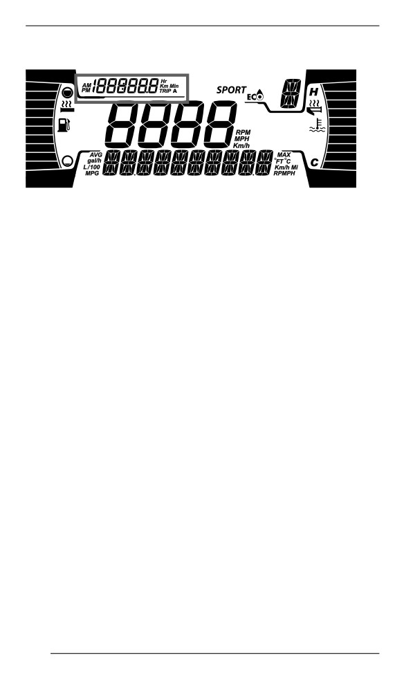
GAUGE - 4.5” DIGITAL DISPLAY
Trip Display
This display shows trip informations:
- Cumulative distance odometer
- Trip A hours
- Trip A distance (Km or mph)
- Vehicle hour meter
- Clock (If battery equipped)
To change the displayed information, use the gauge UPPER (T) but-
ton, or the Trip button on the handlebar multifunction switch, if
equipped.
Warning Lamps and Indicators
The following indicator lamps will alert you to a vehicle condition that
may become serious. Some lamps will illuminate when starting the ve-
hicle to make sure they work. If any lamps remain on after starting the
vehicle, refer to the respective system warning lamp for further
information.
NOTE:
Some warning indicators appear in the display of the multifunction
gauge and function the same as an indicator lamp but do not display
when starting the vehicle.
208
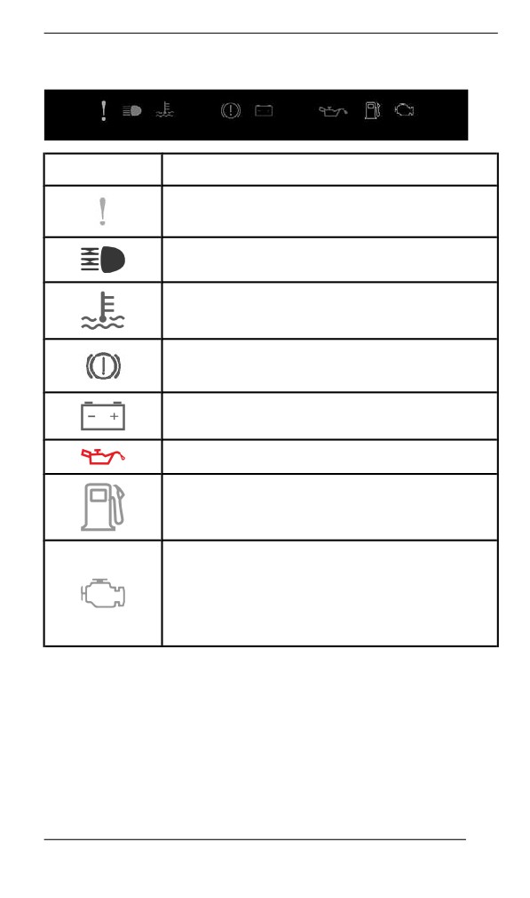
GAUGE - 4.5” DIGITAL DISPLAY
Telltale Lights - Lower Bar
Lights
Description
ORANGE - Vehicle malfunction
BLUE - The high beam are selected
RED - The engine temperature is too high.
RED - Parking brake is engaged or malfunction
of the brake system
RED - The battery voltage too low or problem
with the electrical system
RED - Low injection oil level
ORANGE - Low fuel level
ORANGE
Turn on: Malfunction of the vehicle emissions
control system
Blink: Engine problems, the limp home mode is
activated. Have the vehicle serviced
immediately.
209
GAUGE - 4.5” DIGITAL DISPLAY
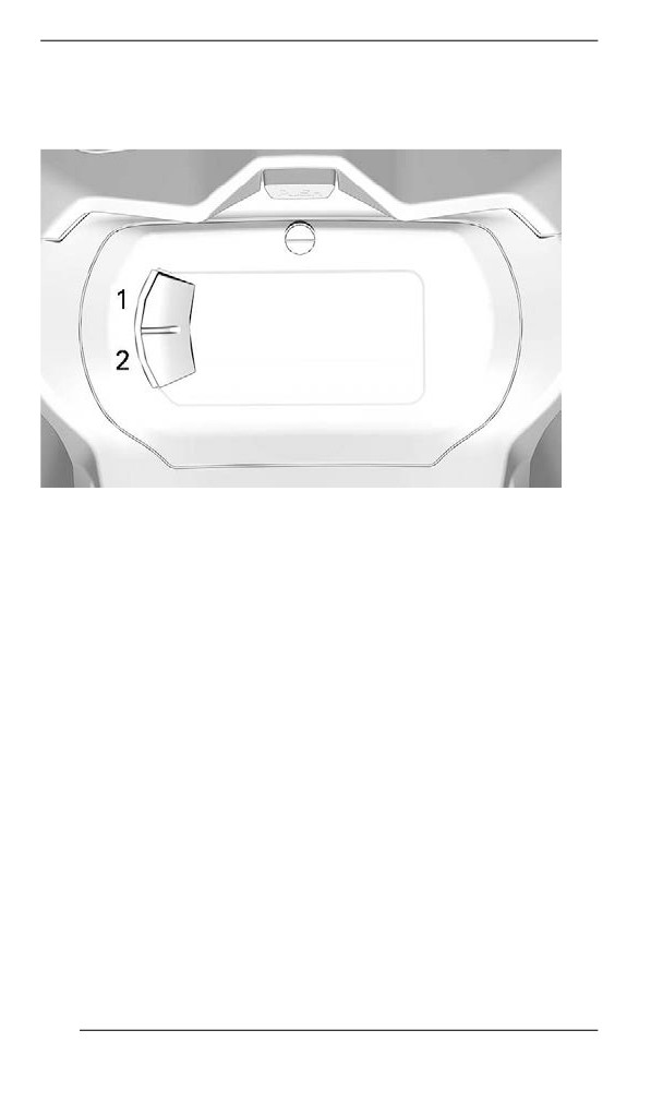
Settings
Setup
1. Upper button (Trip)
2. Lower button (Menu)
NOTE: A Trip and a Menu buttons can be found on the handlebar
multifunction switch, if equipped.
Using the LOWER (M) button, select SETTINGS and hold to enter
setting menu.
Reset Stats
Using LOWER button, select RESET STAT and hold to reset.
Unit Selection
This multifunction gauge is factory preset in metric units but it is possi-
ble to change it to imperial units.
Using LOWER button, select UNITS and hold button to change units.
Setting Clock
Using LOWER button, select CLOCK to change the clock.
1. Press LOWER button to select clock display.
2. Push and hold LOWER button for 1 second.
210
GAUGE - 4.5” DIGITAL DISPLAY
3. Press LOWER button to select 12:00 AM PM or 24:00 time base.
4. Push and hold LOWER button to acknowledge selection.
5. Press LOWER button to change hours (hours flash).
6. Push and hold LOWER button to acknowledge hour selection.
7. Press LOWER button to switch to minutes (minutes flash).
8. Push and hold LOWER button to acknowledge minutes selection.
Setting Language
The gauge display language can be changed. Refer to an authorized
BRP snowmobile dealer for language availability and to setup the
gauge to your preference.
211
GAUGE – 7.2” DIGITAL DISPLAY
Mulltiifunction Diispllay
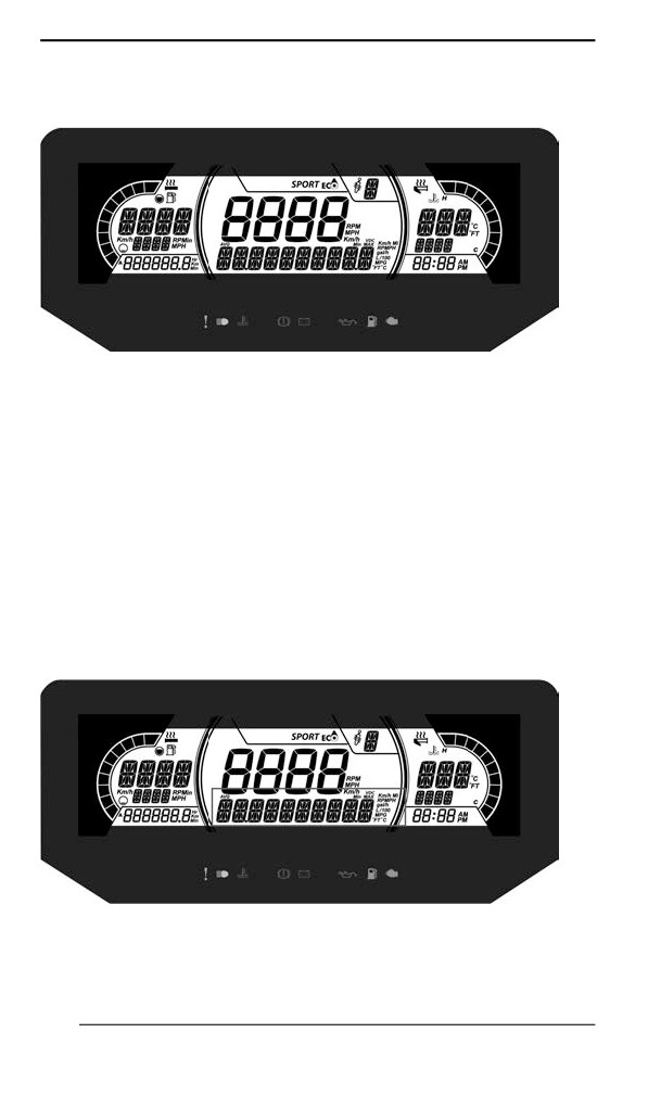
1. Select the upper or center display by using the MENU (M) button
on the multifunction switch. Refer to Secondary Controls for Menu/
Set button location.
2. While the desired display is flashing, navigate through the display,
by using the SET (S) button on the multifunction switch.
Once the desired information is displayed, press the MENU (M)
button or wait 5 seconds to confirm.
To reset
- Average speed
- Top speed
- Total fuel consumption
Press and hold the SET (S) button while display is flashing.
Lower Display
7.2" DIGITAL LOWER DISPLAY
May display the following:
- Settings
212
GAUGE - 7.2” DIGITAL DISPLAY
- Messages
The SPEED display shows the Maximum and the averaged speed.
Hold MENU button for 3 seconds to reset.
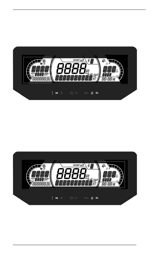
Left Lateral Display
The left lateral display includes:
- Fuel level indicator
- Heated Grip level
- Trip distance A and B (Km or mph)
- Cumulative hours
- Speed
- RPM
- Odometer
Right Lateral Display
The right lateral display includes:
- Engine Temperature
- Heated throttle indicator
- Clock
213
GAUGE - 7.2” DIGITAL DISPLAY
Central Display
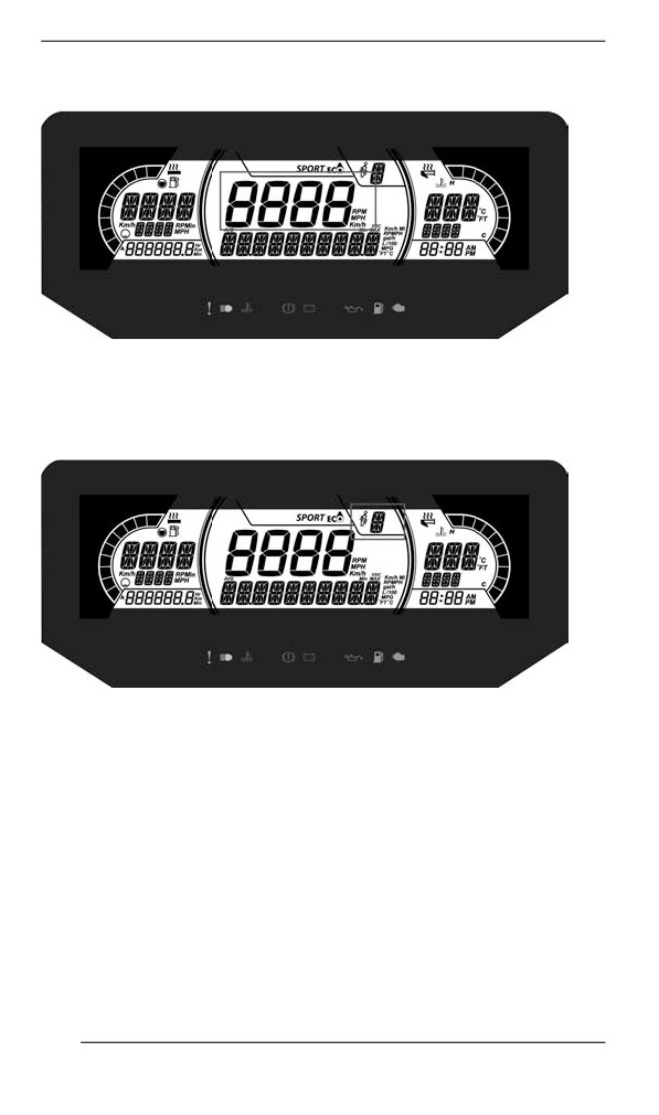
Display the vehicle speed in Km/h (or MPH) or the RPMs. Refer to
Settings.
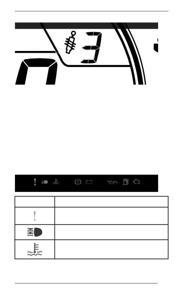
ACS Suspension Position Display (if equipped)
This display shows suspension setting.
The suspension is calibrated from 1 to 5, 1 being the softest setting.
214
GAUGE - 7.2” DIGITAL DISPLAY
Refer to TUNE YOUR RIDE section for proper adjustment procedure.
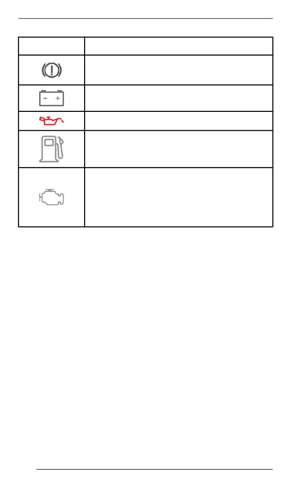
Warniing Lamps and Indiicators
The following indicator lamps will alert you to a vehicle condition that
may become serious. Some lamps will illuminate when starting the ve-
hicle to make sure they work. If any lamps remain on after starting the
vehicle, refer to the respective system warning lamp for further
information.
NOTE:
Some warning indicators appear in the display of the multifunction
gauge and function the same as an indicator lamp but do not display
when starting the vehicle.
Telltale Lights - Lower Bar
Lights
Description
ORANGE - Vehicle malfunction
BLUE - The high beam are selected
RED - The engine temperature is too high.
215
GAUGE - 7.2” DIGITAL DISPLAY
Lights
Description
RED - Parking brake is engaged or malfunction
of the brake system
RED - The battery voltage too low or problem
with the electrical system
RED - Low injection oil level
ORANGE - Low fuel level
ORANGE
Turn on: Malfunction of the vehicle emissions
control system
Blink: Engine problems, the limp home mode is
activated. Have the vehicle serviced
immediately.
Settings
Setup
Using MENU button, select SETTINGS and hold to enter setting
menu. Various options are available such as swapping the SPEED
and RPM in the Central Display.
Unit Selection
This multifunction gauge is factory preset in metric units but it is possi-
ble to change it to imperial units.
Using MENU button, select UNITS and hold button to change units.
Setting Clock
Using MENU button, select CLOCK and hold to change units.
1. Press MENU button to select clock display.
2. Push and hold MENU button for 1 second.
3. Press MENU button to select 12:00 AM PM or 24:00 time base.
4. Push and hold MENU button or OK button to acknowledge
selection.
5. Press MENU button to change hours (hours flash).
6. Push and hold MENU button or OK button to acknowledge hour
selection
216
GAUGE - 7.2” DIGITAL DISPLAY
7. Push MENU button to switch to minutes (minutes flash).
8. Press MENU button to change minutes.
Setting Language
The gauge display language can be changed. Refer to an authorized
BRP snowmobile dealer for language availability and to setup the
gauge to your preference.
217
GAUGE – LARGE PANORAMIC 7.8” WIDE
LCD DISPLAY
Basic Functiions
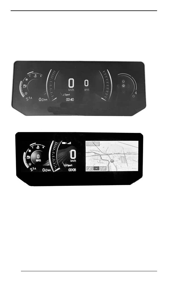
LCD Display
Default Display
Mulltiifunction Diispllay
Left Laterall Diispllay
The left lateral display includes:
- Fuel level indicator
- Engine temperature
- Speedometer
- Tripmeter
- Rpm
- Clock
- Driving modes
- Warning pop-up
218
GAUGE - LARGE PANORAMIC 7.8” WIDE LCD DISPLAY
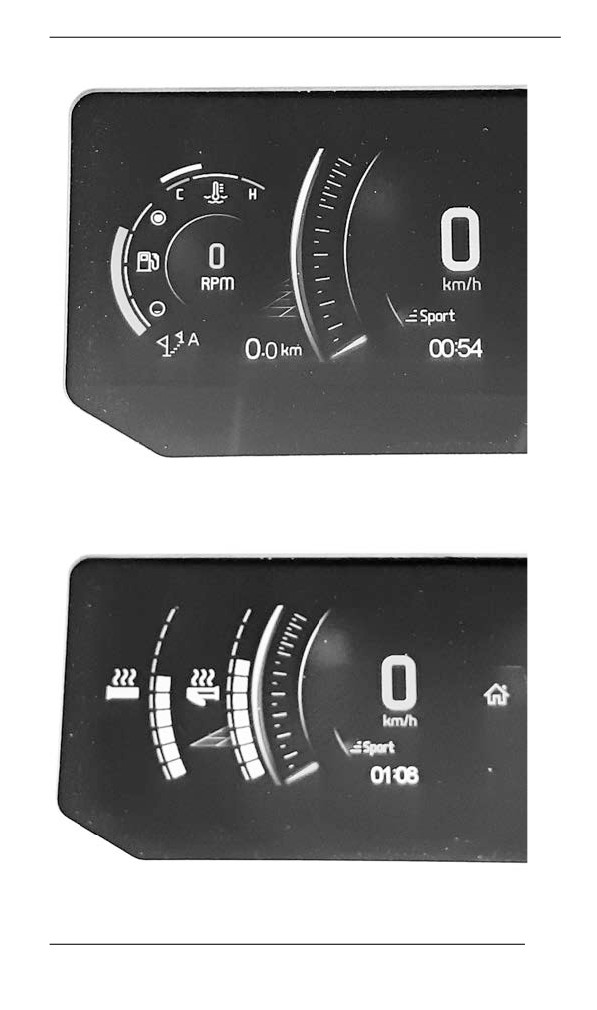
PRINCIPAL VIEW
- Heated grips
- Heated thumb
SECONDARY VIEW - HEATED ELEMENTS
219
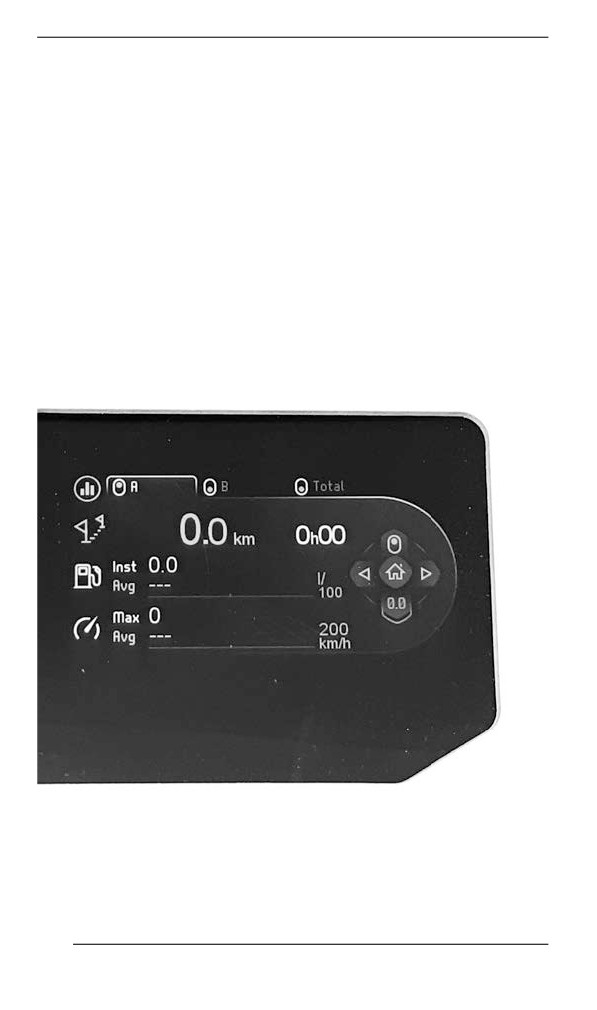
GAUGE - LARGE PANORAMIC 7.8” WIDE LCD DISPLAY
To select the value to be displayed in the tripmeter;
1. Access the Stats/Trip screen
2. Select and activate the desired set of statistic to be shown (Trip A,
Trip B or Total)
Right Lateral Display
The right lateral display includes:
- Tachometer
- Audio volume
- Audio output indicator
- Menu
- BRP Connect
- Phone
- Statistics
- Audio
- Settings
STATS/TRIPS VIEW
220