Snowmobile Polaris ProStar S4, Indy XC 129 / 137, Indy Adventure 137, Voyageur 146, Nordic Pro 146. Owner’s Manual (2024) - page 4
 

  Index      Manuals     Snowmobile Polaris ProStar S4, Indy XC 129 / 137, Indy Adventure 137, Voyageur 146, Nordic Pro 146. Owner’s Manual (2024)


Search            copyright infringement  


Content      ..     2      3      4      5     ..


Snowmobile Polaris ProStar S4, Indy XC 129 / 137, Indy Adventure 137, Voyageur 146, Nordic Pro 146. Owner’s Manual (2024) - page 4


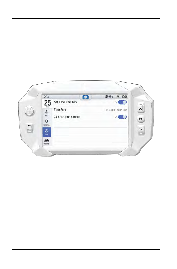
TIME SETTINGS

From the Time Settings tab you can do the following:

• Set time from internal GPS location
• Set time zone
• Set time (if GPS time is not enabled)
• Set date
• Enable GPS Time (automatically sets the time to the time zone you are

currently in)

• Set the time format (12-hour or 24-hour)

102

RIDE COMMAND

VEHICLE SETTINGS

From the Vehicle Settings you can do the following:

• Access vehicle diagnostics
• GPS Status
• Set fuel type
• Customize heated grip temperatures

103

RIDE COMMAND

MAINTENANCE

CARE AND MAINTENANCE

To clean the display shell, use a soft cloth with mild soap and water. Do not use
harsh or abrasive cleaners. For best results, use a micro-fiber towel to clean the
screen.

NOTICE

Certain products will damage the screen and other plastic surfaces. Do not use

alcohol to clean the display. Immediately clean off any gasoline that splashes

on the display.

VEHICLE STORAGE

When preparing the vehicle for storage make sure the ignition switch is in the
OFF position to prevent battery drain and diminished battery life.

SPEED LIMITATION

Various aspects of the display such as the front and rear cameras, phone
contacts, and call logs may be unavailable while driving at high speeds.

UPDATE SOFTWARE

NOTICE

Before updating the Display, always export your existing rides and waypoints

to a USB drive to avoid losing them.

To update the software, do the following:

ON YOUR PERSONAL COMPUTER

1. Go to

ridecommand.polaris.com/update

.

2. Log into your account, or create a new account.

3. Using the Vehicle Identification Number (VIN), add your new Polaris vehicle

to your Garage.

4. Locate and download the latest software to a USB flash drive (8+ GB).

ON YOUR VEHICLE

1. Connect the USB flash drive to the USB cable and power up your vehicle.

2. On the RIDE COMMAND display, select the Settings menu on your display

by pressing the POLARIS icon at the top of the screen.

3. Select General Settings, then Update Software.

104

RIDE COMMAND

4. Select the file you wish to load (use date listed in the file name to determine

most recent file).

5. Select Yes to restart display (restart required).

ERROR MESSAGES

If an error occurs while updating your software, perform one or all of the
following actions to resolve the issue:

1. Remove and reconnect the USB flash drive securely.

2. Make sure the display files are not inside a folder on the flash drive.

3. Make sure only display files are on the flash drive. Remove any other files if

necessary.

4. Try using a different USB flash drive.

UPDATE MAPS

To update the maps on your display, do the following:

1. Go to

ridecommand.polaris.com/update

and download the map update to a

USB flash drive.

2. Insert USB flash drive into the USB port on your vehicle.

3. Press the Update maps in the General Settings.

4. Select the file you want to install by pressing the corresponding down arrow

icon.

5. This will update the display’s map which will automatically restart the display

once the update is complete. Do not remove the USB flash drive until the
display has fully restarted.

USB HARDWARE

SOFTWARE UPDATES

For software update, POLARIS recommends using a SanDisk® or similar USB
flash drive with a minimum of 4GB in available memory, formatted using the
FAT32 or exFAT® file systems. For best results remove all files from the flash
drive before starting the update process.

MAP UPDATES

For Map updates, a 32GB USB drive is required (USB 3.0 drive is highly
recommended) USB drive must be formatted to exFAT® before copying the map
file onto it.

TRAIL UPDATES

For Trail updates, a 4GB drive formatted to FAT32 can be used.

105

RIDE COMMAND

USB PORT

TIP

The USB Port is located in the storage compartment behind the display.

The USB Port makes it easy to power devices, such as phones, audio sources,
or GPS units, in addition to allowing you to stream music through the LCD
display to your Bluetooth® headset.

On models equipped with a Polaris Ride Command display, the USB port is also
used to update the display software. For the latest software, go to

https://ridecommand.polaris.com/en-us/update

.

IMPORTANT

Due to harsh riding environments, Polaris recommends using a USB device

with retention features.

106

RIDE COMMAND

THE PERFECT FIT

SUSPENSION QUICK SET-UP GUIDE

The front and rear suspensions on your Matryx snowmobile are easy to adjust.
Just remember three simple steps:

1. Ride your snowmobile.

2. Adjust the

rear track shock spring

to tune

vehicle balance

(ski pressure and

weight transfer).

3. Adjust

shock clickers

(if equipped) to tune

ride quality

(stiffer or softer ride).

Step 1: Ride your snowmobile.

Ride the snowmobile in various terrain to fully experience the existing
suspension settings before making any adjustments.

Step 2: Adjust the torsion spring settings to tune vehicle balance.

After riding, you should be able to determine if the snowmobile needs more or
less transfer.

• For more transfer,

decrease

the torsion spring setting.

• For less transfer,

increase

the torsion spring setting.

If you prefer your snowmobile has lighter steering, decrease the torsion spring
setting or increase the front track shock spring preload.

Step 3: Adjust shock clickers (if equipped) for ride quality.

For models equipped with monotube shocks, always adjust the rear track shock
spring preload to enhance bottoming resistance.

For models with shock clickers, you can adjust the clickers to control bottoming
and adjust ride comfort.

• Turn a clicker counter-clockwise to decrease damping for a softer ride.
• Turn a clicker clockwise to increase damping for a stiffer ride and less

bottoming.

NOTICE

Always adjust the clicker at least one click below full stiff (full clockwise) or

shock damage will occur.

Test ride the snowmobile and continue making spring and clicker adjustments
until you achieve the perfect ride.

107

THE PERFECT FIT

SHOCK LOCATIONS

q

Rear track shock

w

Front track shock

e

Front (IFS) shocks

SHOCK COMPRESSION DAMPING

The primary adjustment for overall vehicle balance is torsion spring preload.
Perform this adjustment first. After adjusting torsion spring preload to your
satisfaction, compression damping adjustments can be made to control ride
quality and bottoming resistance.

Compression damping can be adjusted at the front suspension and at the front
and rear track shock. Make adjustments in 2-click increments, then test ride.
When adjusting the front suspension, always adjust both clickers equally.

To stop bottoming

of the front or rear suspension (stiffer ride), rotate the clicker

(s) clockwise two clicks (as viewed from the top of the clicker), then test ride.
Repeat the adjustment until bottoming stops and the desired ride quality is
achieved.

For a more plush ride

at the front or rear suspension, rotate the clicker(s)

counter-clockwise two clicks, then test ride. Repeat the adjustment until the
desired ride quality is achieved.

108

THE PERFECT FIT

TORSION SPRING ADJUSTMENTS

To adjust rear torsion spring preload, rotate the three-position cam

q

using the

engine spark plug tool. Adjustment is easiest when the cam is rotated from low
to medium, and then to high. Rotating directly from low to high will require
significantly more effort. Different rate torsion springs are available if a firmer
ride is desired. See your dealer for more information.

NOTE

Adding 1+1 seat, or additional cargo may affect handling and require a spring

rate change.

TORSION
SPRING
SETTING

RECOMMENDED USAGE

Low

Rider(s) and gear =140-180lb
If less than 140, use the optional spring chart for softer
springs.

Medium

Rider(s) and gear = 180-220lb

High

Rider(s) and gear = 220-260lb
If above 260, use the optional spring chart for heaver
springs.

109

THE PERFECT FIT

REAR TORSION SPRING KITS

All AXYS and MATRYX vehicles are equipped with standard stock rear track
suspension springs. To customize your ride, rear torsion spring kits can be
installed to accommodate your particular total rider weight range.

KIT DESCRIPTION

PART NUMBER

WEIGHT RANGE –
LBS (KG)

Factory-Installed Stock
Spring

7045190, 7045191

140-260 lb (64-118 kg)

Factory-Installed Stock
Spring (144/146)

7041629, 7041630

140-260 lb (64-118 kg)

Factory-Installed Stock
Spring (Adv X2)

7045924, 7045925

129/137 Light Duty

2884973

0-180 lb (0-82 kg)

144/146 Light Duty

2884976

0-180 lb (0-82 kg)

129/137 Heavy Duty

2884974

220-350 lb (100-159 kg)

144/146 Heavy Duty

2884977

220-350 lb (100-159 kg)

129/137 Extra Heavy
Duty

2884975

310-425 lb (141-193 kg)

110

THE PERFECT FIT

FRONT SUSPENSION (IFS) SHOCK SETTINGS

Always perform shock spring preload adjustments with the weight of the vehicle
removed from the shock and with the shock at full extension.

POLARIS IFP

MODEL

Matryx Nordic Pro

Matryx Voyageur

FACTORY INSTALLED
LENGTH

10.92 in (27.74 cm)

10.92 in (27.74 cm)

MINIMUM INSTALLED
LENGTH

9.67 in (24.56 cm)

9.67 in (24.56 cm)

FACTORY CLICKER
SETTING*

No clicker

No clicker

111

THE PERFECT FIT

POLARIS TS

MODEL

INDY Adventure

INDY XC

INDY Adventure

X2

FACTORY
INSTALLED
LENGTH

10.05 in (25.53

cm)

10.05 in (25.53

cm)

10.05 in (25.53

cm)

MINIMUM
INSTALLED
LENGTH

8.55 in (21.72

cm)

8.55 in (21.72

cm)

8.55 in (21.72

cm)

FACTORY
CLICKER
SETTING*

Medium

Medium

Medium

*

From Full Stiff

FRONT TRACK SHOCK SETTINGS

Factory settings, combined with user adjustments to the rear track shock spring
(RTSS), should be all that’s necessary to provide the best riding experience for
most riders. The primary adjustment for overall vehicle balance is RTSS
preload. Perform this adjustment first.

Always perform shock spring preload adjustments with the weight of the vehicle
removed from the shock, limiter strap(s) disconnected, and the shock at full
extension.

NOTICE

Never adjust spring preload to an installed length longer than the factory length

or shorter than the minimum length as shown in the following chart. Damage to

the suspension could result. When decreasing preload, make sure at least two

turns of preload are holding the retainer against the spring.

The front track shock is measured from the bottom of the spring to the top of the
body cap.

112

THE PERFECT FIT

POLARIS IFP

MODEL

FACTORY

INSTALLED

LENGTH

MINIMUM

INSTALLED

LENGTH

FACTORY

CLICKER

SETTING

Nordic Pro

8.38 in (21.29
cm)

6.63 in (16.84
cm)

No clicker

Voyageur

8.38 in (21.29
cm)

6.63 in (16.84
cm)

No clicker

Indy Adventure

7.47 in (18.97
cm)

7.22 in (18.34
cm)

No clicker

Indy XC

7.47 in (18.97
cm)

7.22 in (18.34
cm)

No clicker

Indy Adventure
X2

8.34 in (21.18
cm)

6.59 in (16.74
cm)

No clicker

113

THE PERFECT FIT

REAR TRACK SHOCK SETTINGS

Always perform shock spring preload adjustments with the weight of the vehicle
removed from the shock and with the shock at full extension.

To reset shock clickers, rotate the clicker to full stiff, and then back off the same
number of clicks for each shock.

POLARIS IFP

Nordic Pro and Voyageur models are equipped with Polaris IFP monotube rear
track shocks. These shocks are non-adjustable. Adjust the front track shock
spring and torsion springs for additional weight transfer.

MODEL

Matryx Nordic Pro

Matryx Voyageur

FACTORY INSTALLED
LENGTH

No Spring

No Spring

FACTORY CLICKER
SETTING

No clicker

No clicker

114

THE PERFECT FIT

POLARIS TS

MODEL

Indy Adventure

Indy XC

Indy Adventure

X2

FACTORY
INSTALLED
LENGTH

No Spring

No Spring

No Spring

FACTORY
CLICKER
SETTING*

Medium

Medium

Medium

*

From Full Stiff

115

THE PERFECT FIT

REAR REAR SCISSOR STOP (RRSS) (IF
EQUIPPED)

REAR REAR SCISSOR STOP (RRSS) - ATTRIBUTES

Moving the RRSS to a higher position will have the following effects on the
suspension:

• Reduced weight transfer
• Improved chatter bump ride
• Improved cornering performance
• Increased load carrying capacity (2–up)

WEIGHT TRANSFER DURING ACCELERATION

The preferred method for controlling weight transfer during acceleration is by
adjusting the rear rear scissor stop (RRSS). The factory setting is the best for
most trail riding conditions.

To decrease weight transfer under acceleration (for improved cornering), rotate
the RRSS to a higher position.

To increase weight transfer or ski lift during acceleration, rotate the RRSS to a
lower position.

NOTICE

When adjusting for weight transfer, both the left and right rear rear scissor stop

adjuster blocks must be adjusted to the same position.

116

THE PERFECT FIT

q

High

w

Medium

e

Low

r

Low

TIP

Your dealer can help you with initial setup and additional setup instructions to
help you achieve your optimum ride. A scissor stop tool is also available from

your dealer.

117

THE PERFECT FIT

HANDLEBAR COMPONENT FASTENER
TORQUES

IMPORTANT

Moving a handlebar component without first loosening its screws/set screws

may cut grooves into the handlebar, making it difficult to secure the

component. Do not move a handlebar component without first loosening its

mounting screws/set screws. Take care to avoid damaging hand warmer/brake

switch wires when moving components.

COMPONENT

TORQUE

DO NOT OVER-TIGHTEN

q

Upper / Lower Riser Clamps

14.8 ft-lbs (20 N·m)

w

Throttle Block Clamp Screw

20 in-lbs (2.3 N·m)

e

Engine Stop Switch Clamp Screw

20 in-lbs (2.3 N·m)

r

Brake Lever / Master Cylinder

70 in-lbs (7.9 N·m)

t

Left Hand Control Block

20 in-lbs (2.3 N·m)

Not Shown

Hand Guard Mounts (if applicable)

Hand-Tighten

118

THE PERFECT FIT

BRAKE MASTER CYLINDER ALIGNMENT

CAUTION

Take care to avoid damaging hand warmer/brake switch wires when moving

components.

1. Loosen the mounting screw

q

.

2. Move the master cylinder to

the desired position.

3. Tighten the screw to

specification. Do not
over-torque.

TORQUE

Master Cylinder Mounting Screw

60-80 in-lbs (6.7-9 N·m)

THROTTLE BLOCK ALIGNMENT

1. Slightly loosen the throttle block

clamp screw

q

.

2. Move the throttle block to the

desired position.

NOTICE

Take care to avoid damaging hand

warmer wires when moving

components.

3. Tighten the screw to specification. Do not over-torque.

TORQUE

Throttle Block Clamp Screw

27 in-lbs (3 N·m)

4. With the engine off, test throttle lever movement after tightening the screw.

119

THE PERFECT FIT

ENGINE STOP SWITCH ALIGNMENT

1. Slightly loosen the set screw

q

on the bottom of the

housing.

2. Move the switch to the

desired position.

3. Tighten the screw to

specification. Do not
over-torque.

CAUTION

The stop switch must be positioned in an easily accessible location.

TORQUE

Stop Switch Set Screw

20 in-lbs (2.3 N·m)

RISER ANGLE

Riser angle can be adjusted to suit
rider preference.

1. Loosen the four bolts

q

on the

bottom of the adjuster block. If
necessary, pry the blocks apart
with a screwdriver.

2. Adjust the riser forward or

rearward to the desired position.

3. Torque the bolts to specification.

TORQUE

Adjuster Block Bolts

14.8 ft-lbs (20 N·m)

120

THE PERFECT FIT

HANDLEBAR ANGLE

Handlebar angle can be
adjusted to suit rider preference.

1. Loosen the four bolts

q

on

the top riser block.

2. Adjust the handlebar upward

or downward to the desired
angle. Be sure the
handlebar, brake lever and
throttle lever operate
smoothly and do not hit the
gas tank, windshield or any
other part of the machine
when turned fully to the left or
right.

If necessary, loosen the set screws for the left and right controls, rotate the
controls

slightly

, then tighten the set screws to the proper torque.

3. Torque the bolts to specification.

TORQUE

Handlebar Block Bolts

14.8 ft-lbs (20 N·m)

NOTICE

Do not stretch wires while adjusting the controls. Stretching the wires could

damage the handwarmers.

TRACTION PRODUCTS

TRACK STUDDING

Track studding will enhance braking control on hard-packed snow or ice, but
extreme caution is still required on such surfaces. Steering ability may be
reduced on hard-packed snow or ice.

When studded tracks are used, increased wear to the brake pads will result from
increased braking and requires increased brake inspection intervals.

Installing studs can also cause the track to stretch more than a non-studded
track. For this reason, POLARIS recommends inspecting track tension more
often and setting the tension at the preferred measurement.

121

THE PERFECT FIT

Always adhere to the manufacturer’s stud maintenance procedures and stud nut
torque specifications.

Before equipping your snowmobile with traction products, be aware of
regulations pertaining to the use of traction products in your area of operation.

STUDS

NOTICE

Failure to heed the following recommendations will result in tunnel or track

damage and a voided warranty.

Track damage resulting from improperly installed or maintained studs is not
covered under warranty. Use only POLARIS-approved traction products on your
snowmobile. See your dealer for more information about installing studs and/or
carbides.

NOTICE

Use of studs longer than the recommended length on snowmobiles equipped

with center coolers will result in center cooler damage or damage to the tunnel.

The Matryx chassis requires a stud protection kit to be installed before installing
studs or chassis damage will occur. This stud protection kit will protect against
chassis damage with the following track/stud combinations.

CHASSIS/TRACK

STUD PROTECTION KIT

Matryx 129 / Storm 150

PN: 2884961

Matryx 137 / Cobra / Ice Ripper

PN: 2884962

Matryx 146 / Cobra 1.3

PN: 2884963

• 1.325 in Polaris/Woody’s® studs installed in a Ripsaw II 1.25 in or Cobra

1.352 in track .

• 1.575 in Polaris/Woody’s® studs installed in a Storm 150 track, center band

only.

122

THE PERFECT FIT

q

Penetration Range 1/4 - 3/8 in (6-9 mm)

w

Stud Size

e

Track Lug Height

r

Track Belt Thickness

CARBIDE SKAGS

A skag is a replaceable bar attached to the underside of the ski to assist in
turning the snowmobile and to prevent ski wear caused by contact with roads
and other bare terrain. See page 189.

123

THE PERFECT FIT

124

PRE-RIDE INSPECTIONS

PRE-RIDE CHECKLIST

Inspect all items on the checklist for proper operation or condition before each
use of the snowmobile. Procedures are outlined in the referenced sections.

ITEM

SEE SECTION

Drive Belt

page 171

Steering System

page 186

Coolant Level

page 163

Transmission Oil Level

page 176

Oil Level Check

page 151

Brake System

page 128, page 129, and page 164

Auxiliary Shut-Off Switch (Engine
Stop Switch)

page 138

Ignition Switch

page 33

Headlight/Taillight/Brakelight

page 131

Suspension Mounting Bolts

page 126

Skags (Wear Bars)

page 189

Ski Saddle and Spindle Bolts

page 126

Hood and Side Panel Fasteners

page 130

Throttle Lever

page 127

Rear Wheel Idler Bolt

page 183

Tether Switch/Strap (if equipped)

page 130

Track Alignment/Condition

page 130 and page 185

Rail Slide Condition

page 190

125

PRE-RIDE INSPECTIONS

PRE-RIDE SUSPENSION INSPECTION

Loose nuts and bolts can reduce your snowmobile's reliability and cause
needless repairs and down time. Before beginning any snowmobile trip, a visual
inspection will uncover potential problems. Check the following items on a
weekly basis or before any long trip.

ITEM

SEE SECTION

Check suspension mounting bolts for
tightness.

-

Check rear idler wheel bolt for
tightness.

page 183

Check rear idler adjusting bolt
locknuts for tightness.

-

Check front torque arm limiter strap
condition.

-

Check rail slide condition.

page 190

Check track tension.

page 183

Check ski runner/skag condition.

page 189

Check ski spindle bolts for tightness.

-

Check tie rod end nuts for tightness.

-

126

PRE-RIDE INSPECTIONS

BEFORE STARTING THE ENGINE

Before starting the engine, always refer to all safety warnings pertaining to
snowmobile operation. Never start the engine without checking all vehicle
components to be sure of proper operation.

WARNING

Operating the vehicle with worn, damaged, contaminated, or malfunctioning

components could result in serious injury or death. Never start the engine

without checking all vehicle components to be sure of proper operation.

READ AND UNDERSTAND YOUR OWNER'S
MANUAL

Read the Owner's Manual completely and refer to it often. The manual is your
guide to safe and enjoyable snowmobiling experience.

STEERING SYSTEM

WARNING

Ice and snow build-up may interfere with the steering of your snowmobile,

resulting in serious injury or death. Keep the underhood area free of snow and

ice.

Before driving, manually turn the skis to the left and right to be sure ice and
snow are not interfering with full left and right steering. If difficulty is
encountered, remove ice and snow build-up that may be obstructing the steering
linkage.

THROTTLE LEVER

The throttle lever

q

and brake

are the primary controls of your
snowmobile. Always make sure
both are functioning properly.

127

PRE-RIDE INSPECTIONS

Squeeze the throttle lever to make sure it compresses evenly and smoothly.
When released, the lever should immediately return to the idle position without
binding or hesitation. If the throttle does not function smoothly, or if you discover
excessive lever freeplay, DO NOT start the engine. Have the throttle serviced
immediately.

BRAKES

Always check the following items for proper operation before starting the engine.

BRAKE LEVER TRAVEL

Squeeze the brake lever. It
should move no closer to the
handgrip than 0.5 in (1.3 cm)

q

.

A smaller distance indicates low
brake fluid level or air in the
hydraulic system. Refer to the
brake bleeding information on
page 166. Your dealer can
assist.

LEVER FEEL

If the brake lever feels “spongy” when squeezed, check the brake fluid level and
condition. Add fluid as needed. See the Brake Fluid section for details.

WARNING

Continued use of “spongy” brakes may cause a complete loss of brakes, which

could result in serious injury or death. Always have the brakes serviced at the

first sign of sponginess.

128

PRE-RIDE INSPECTIONS

PARKING BRAKE LEVER LOCK

Use the parking brake lever lock only when you want the snowmobile to remain
stationary; for example, when parked on an incline for a period of five minutes or
less.

1. Brake Lever

2. Parking Brake Lever Lock

3. Master Cylinder

Reservoir/Cover

LOCK ENGAGEMENT

To engage the lock, squeeze the brake lever tightly and push forward on the
lock. Hold the lock forward while releasing the brake lever.

NOTICE

If the brake lever is squeezed tightly enough, the lock will move freely into

place. Do not force the lock or it may break.

The parking brake light on the gauge will light up if the parking brake lever lock is
set while the engine is running. It will also be lit when the service brake is in use.
If the parking brake light does not come on when the parking brake or service
brake is in use, have it serviced by your dealer.

LOCK RELEASE

To release the lock, squeeze the brake lever tightly. The lock will return to the
unlocked position.

WARNING

If the parking brake lever lock is partially or entirely engaged while riding, the

brakes may overheat, resulting in brake damage. In extreme cases it could

cause a fire, which could result in serious injury or death. Always ensure that

the lever lock is completely disengaged before operating the snowmobile.

129

PRE-RIDE INSPECTIONS

TRACK

Track damage or failure caused by operation on ice or poor lubrication
conditions voids the track warranty.

WARNING

Operating the snowmobile with a damaged track increases the possibility of

track failure, which could cause loss of control resulting in serious injury or

death. Always inspect the track for damage before using the vehicle.

WARNING

Use of traction products such as studs increases the possibility of track

damage and/or failure. Driving at high speeds for extended periods of time in

marginal lubrication could severely damage track rods, break track edges, and

cause other track damage. Examples of marginal lubrication would include

frozen bodies of water without snow cover, icy trails, and no-snow conditions.

HOOD AND SIDE PANEL FASTENERS

CAUTION

The hood and side panels of the snowmobile protect the operator from moving

parts. Never operate a snowmobile with the hood or side panels open or

removed. Always ensure that the hood and side panels are securely in place

before starting the engine.

START THE ENGINE AND CHECK

Before starting the engine, always refer to all safety warnings pertaining to
snowmobile operation. Never engage the starter when the engine is running.
Never start the engine without checking all vehicle components to be sure of
proper operation. See page 127.

ENGINE STOP SWITCH

Check the auxiliary shut-off switch for proper operation. Push the switch down to
stop the engine. Pull it up to allow restarting.

IGNITION SWITCH

Make sure the engine stops when the ignition switch is turned to OFF.

TETHER SWITCH (IF EQUIPPED)

If your snowmobile has a tether switch, remove the tether from the switch to
make sure the engine stops immediately.

130

PRE-RIDE INSPECTIONS

LIGHTING

Check the headlight (high and low beam), taillight, and brake light. Replace
burned out lamps before operating.

MIRRORS (IF EQUIPPED)

Adjust the mirrors so they can be used to their full advantage.

OPERATING AREA

Before driving away, check your surroundings. Be aware of obstacles and make
sure bystanders are a safe distance from the snowmobile.

131

PRE-RIDE INSPECTIONS

OPERATION

STARTING THE ENGINE

1. Apply brake.

NOTICE

Engine will not start if brake lever is not actuated.

2. Turn the key to the ON position.

3. Pull the engine stop switch up to the RUN position.

4. Turn the key to START to crank the engine. Release the key to the ON

position when the engine starts.

5. If engine does not immediately start, hold the key in the START position for a

maximum of 10 seconds, or until the engine starts. Repeat if necessary.
When possible, use block heater for assistance with starting in colder
temperatures.

CAUTION

To avoid injury and/or engine damage, do not operate the electric starter while

the engine is running.

NOTICE

Operating the vehicle immediately after cold starting could cause engine

damage. Allow the engine to warm up for several minutes before operating the

vehicle. If cold drive-away is attempted, the engine RPM may stumble slightly

to protect the engine.

RESTARTING THE ENGINE

If the rider stops the engine by pushing the engine stop switch down, restart the
engine using the normal starting procedure. If the engine fails to start using the
normal procedure:

1. Push the engine stop switch down to the OFF position.

2. Turn the key to the OFF position.

3. Reset the engine stop switch.

4. Turn key to the ON position. Wait for the fuel pump to stop running.

5. Crank the engine up to 10 seconds.

6. If engine fails to start, repeat steps 1-5.

133

OPERATION

EXTREME COLD RESTARTING

For better cold restarting performance, do the following after engine shutdown
when the engine will be at rest for more than 2 hours and ambient temperatures
fall below 0 °F (-18 °C). This procedure ensures the maximum amount of oil has
been pumped from the crankcase to the external oil bottle and reduces cranking
friction.

1. Shut off the engine and wait 10 seconds.

2. Restart the engine.

3. Allow engine to idle for 10 seconds. Do not increase RPM.

4. Shut off the engine.

5. When starting a cold engine, continue to hold the ignition key in the START

position for 3 seconds following first combustion events. Keeping the starter
engaged helps the engine continue firing if there is poor combustion due to
the extreme cold.

134

OPERATION


Content      ..     2      3      4      5     ..