Snowmobile Lynx 59 RANGER 600 EFI. OPERATOR’S GUIDE (2024) - page 3
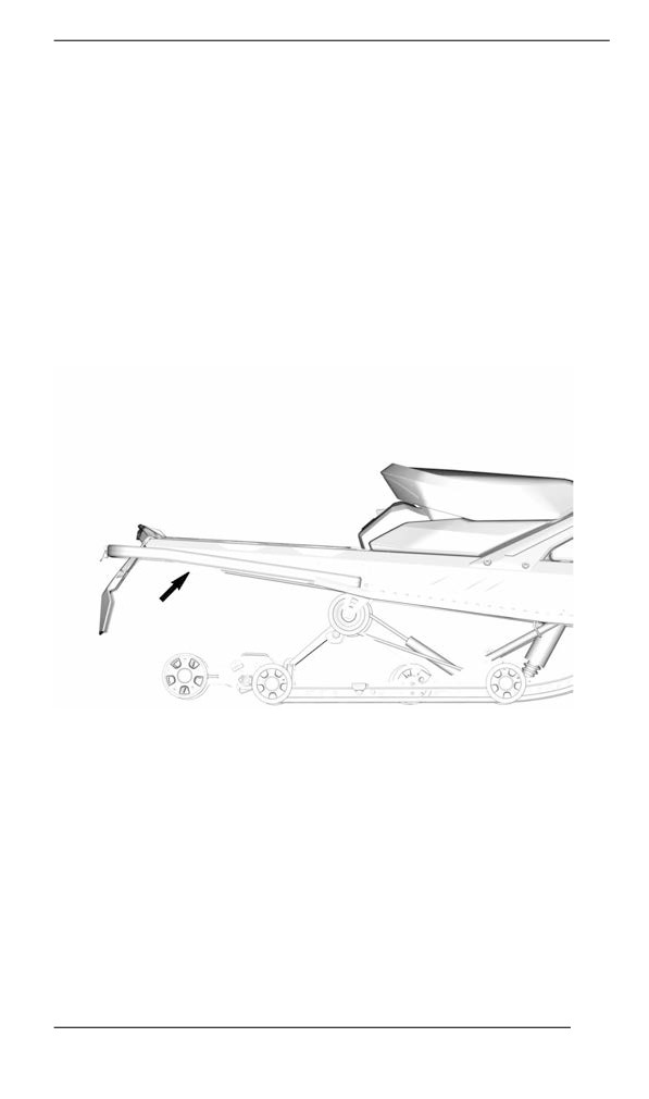
TUNE YOUR RIDE
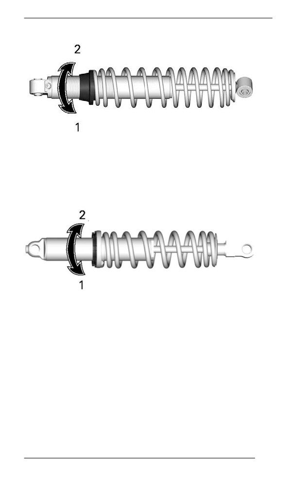
1. Increase preload
2. Decrease preload
Ring Adjuster – Type 2
Grab and turn the ring and the spring to increase or decrease the
spring preload.
1. Increase preload
2. Decrease preload
145
TUNE YOUR RIDE
Rear Suspensiion Adjustments
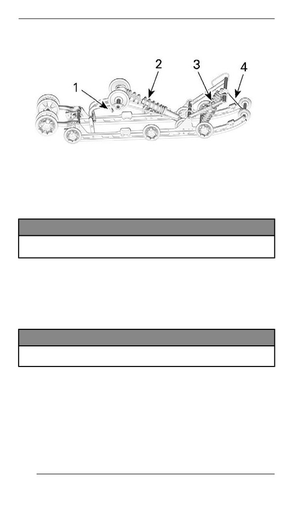
EASYRIDE - ADJUSTABLE COMPONENTS
1. Easy Adjust Handle (if equipped)
2. Rear spring
3. Center spring
4. Stopper strap
NOTICE
Whenever adjusting rear suspension, check track tension and
adjust if necessary.
Stopper Strap – EasyRide Suspension
Stopper strap length has an effect on the amount of weight the center
spring has to carry especially during acceleration, therefore on the
front end uplift.
Stopper strap length also has an effect on center spring travel.
NOTICE
Whenever stopper strap length is changed, track tension must
be checked.
NOTE:
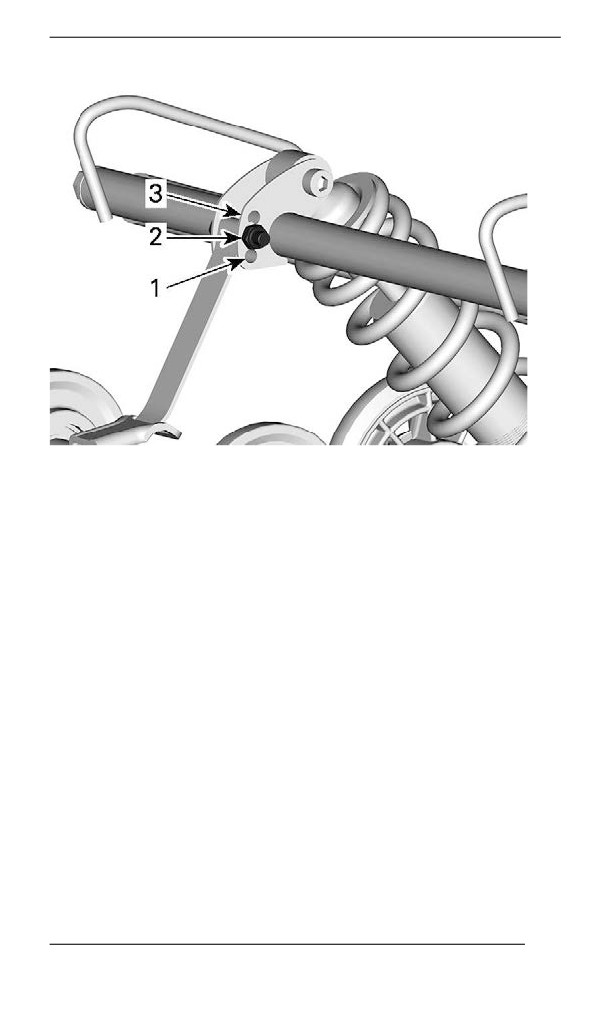
Stopper strap can be set to position 1, 2 or 3. Smaller numbers corre-
spond to a longer strap setting.
146
TUNE YOUR RIDE
STOPPER STRAP POSITIONS
1. Position 1 (longest)
2. Position 2
3. Position 3 (shortest)
When operating the snowmobile in deep snow or hill climbing, it may
be necessary to vary stopper strap length and/or riding position, to
change the angle at which the track rides on the snow. Operator's fa-
miliarity with the various adjustments as well as snow conditions will
dictate the most efficient combination.
Generally, a longer stopper strap setting gives better performance on
a flat landscape and a shorter setting will improve handling in steep hill
climbing and deep snow conditions.
147
TUNE YOUR RIDE
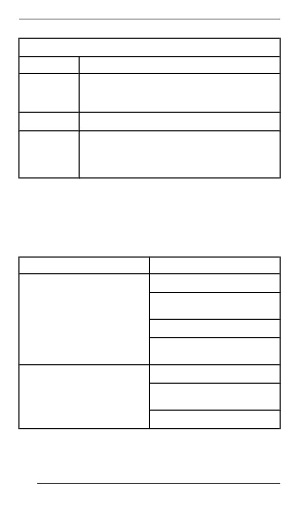
Stopper Strap Setting
Position
Use
Boon docking:
1
- Better bump absorption
- Lighter and easier handling on flat landscape.
2
Standard setting: Best overall setting (general use)
Hill climb:
- Better track attack angle for hill climbing
3
- Less transfer
- Lower ride height
Center Spring
Center spring preload has an effect on steering effort, handling and
bump absorption.
Also, since center spring preload adjustment puts more or less pres-
sure on the front of the track, it has an effect on the performance in
deep snow.
Action
Result
Lighter steering
More bump absorption
capability
Increasing preload
Better deep snow starts
Better deep snow performance
and handling
Heavier steering
Less bump absorption
Decreasing preload
capability
Better trail handling
Cam Type Adjuster
148
TUNE YOUR RIDE
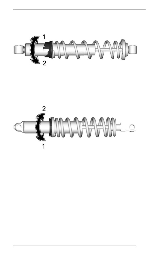
Using the suspension adjustment tool provided in the tool kit, turn the
cam to increase or decrease the spring preload.
1. Increase preload
2. Decrease preload
Ring Type Adjuster
Grab and turn the ring and the spring to increase or decrease the
spring preload.
1. Increase preload
2. Decrease preload
Rear Spring
Rear spring preload has an effect on comfort, ride height and load
compensation.
Also, adjusting rear spring preload shifts more or less weight to the
snowmobile front end. As a result, more or less weight is applied to
the skis. This has an effect on performance in deep snow, steering ef-
fort and handling.
Slight suspension bottoming occurring under the worst riding condi-
tions indicates a good choice of spring preload.
149
TUNE YOUR RIDE
Action
Result
Firmer rear suspension
Higher rear end
Increasing preload
More bump absorption capability
Heavier steering
Softer rear suspension
Lower rear end
Less bump absorption capability
Decreasing preload
Lighter steering
Better deep snow performance and
handling
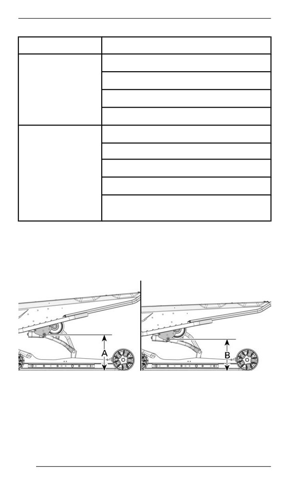
Refer to the following to determine if preload is correct.
- A = Suspension fully extended
- B = Suspension has collapsed with operator, passenger(s) and
load added
- C = Distance between dimension “A” and “B”, see table below
TYPICAL - DISTANCE BETWEEN GROUND AND UPPER REAR
ARM PIVOT
150
TUNE YOUR RIDE
C
What to do
90 to 100 mm (3.6 to 4 in)
No adjustment required
More than
Adjusted too soft. Increase
100 mm (4 in)
preload
Less than
Adjusted too firm. Decrease
90 mm (3.6 in)
preload
NOTE:
If the specification is unattainable with the original springs, visit an au-
thorized BRP snowmobile dealer for other available springs.
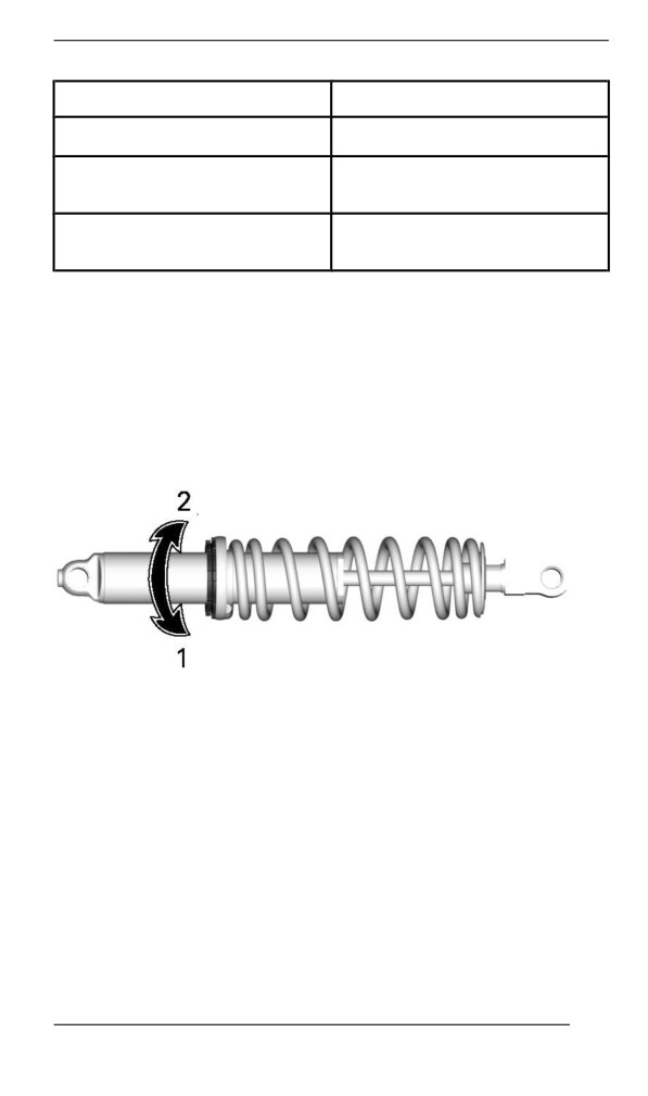
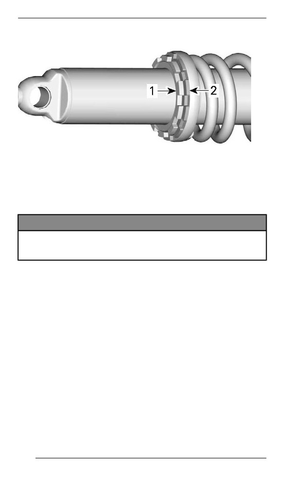
Using the suspension adjustment tool provided in the tool kit, unscrew
the lock ring and turn the adjustment ring to increase or decrease the
spring preload.
Tighten the lock ring when the adjustment is done.
1. Increase preload
2. Decrease preload
151
TUNE YOUR RIDE
1. Locking ring
2. Adjustment ring
Load Capacity Adjustment (If Equipped)
Some EasyRide suspension have an additional adjustment for the
rear suspension load capacity.
NOTICE
The adjustment must always be tightened all the way to either
end of the adjustment. Do not leave the adjustment in between
of these positions, damage can occur.
To adjust proceed as follows:
Hard Setting
152
TUNE YOUR RIDE
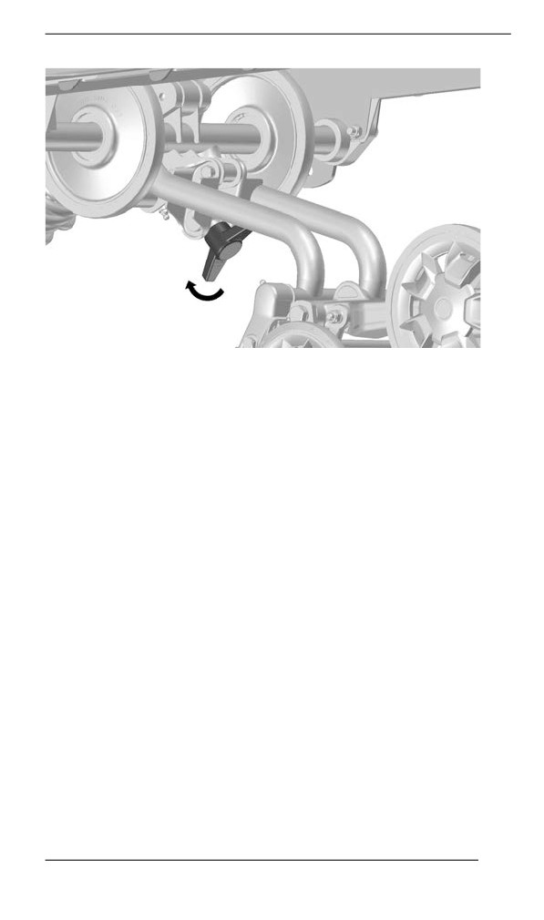
TURN HANDLE ALL THE WAY CLOCKWISE
- HARDER
SUSPENSION
Turn handle clockwise completely for harder suspension.
NOTE:
Ensure the limiter is touching the rear arm bracket.
153
TUNE YOUR RIDE
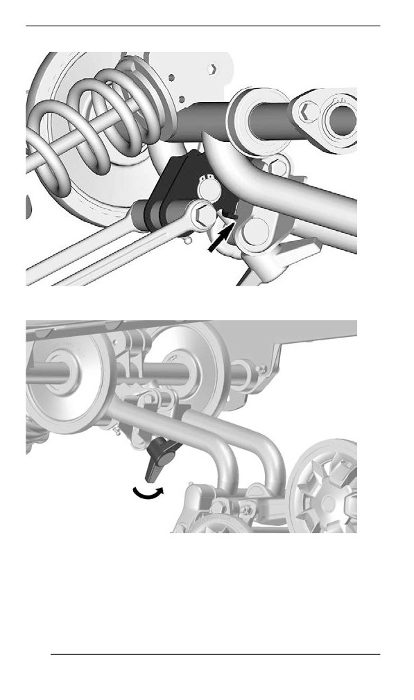
Soft Setting
TURN HANDLE ALL THE WAY COUNTERCLOCKWISE
-
SOFTER SUSPENSION
Turn handle counterclockwise completely for softer suspension. (Fac-
tory setting)
154
TUNE YOUR RIDE
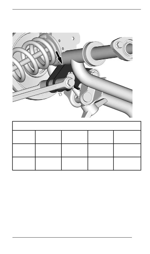
NOTE:
Ensure the limiter is touching the rear arm tube.
Adjustment chart
Comfort
Comfort
Carrying
Hauling
(1-up)
(2-up)
cargo
heavy loads
Soft
X
X
Setting
Hard
X
X
Setting
155
TUNE YOUR RIDE
Adjjustment Tips Accordiing to Vehicle Behavior
Problem
Corrective Measures
Check ski alignment.
-
Reduce front suspension spring
Front suspension darting
preload.
-
Increase center spring preload.
–
Reduce rear spring preload.
Steering feels too heavy
-
Reduce front suspension spring
at steady speeds
preload.
-
Increase center spring preload.
Steering feels too heavy
-
Reduce rear spring preload.
during acceleration
-
Lengthen limiter strap.
Too much ski lift during
-
Shorten limiter strap.
cornering or acceleration
–
Increase rear spring preload.
Rear of snowmobile
-
Reduce rear spring preload.
seems too stiff
Rear of snowmobile
-
Increase rear spring preload.
seems too soft
-
Increase rear spring preload.
Rear suspension is
–
Increase center spring preload.
frequently bottoming
–
Lengthen limiter strap.
-
Reduce center spring preload.
Snowmobile seems to
–
Increase rear spring preload.
pivot around its center
-
Increase front suspension spring
preload.
-
Shorten limiter strap.
-
Lengthen limiter strap.
Track spins too much at
-
Reduce rear spring preload.
start
–
Increase center spring preload.
156
MAINTENANCE
157
MAINTENANCE SCHEDULE
Maintenance is very important to keep your vehicle in safe operating
condition. The vehicle should be serviced as per the maintenance
schedule.
Proper maintenance is the owner’s responsibility. A warranty claim
may be denied if, among other things, the owner or operator caused
the problem through improper maintenance or use.
Perform periodic checks and follow the maintenance schedule. The
maintenance schedule does not exempt the pre-ride inspection.
WARNING
Failure to properly maintain the vehicle according to the main-
tenance schedule and procedures can make it unsafe to
operate.
Deep Snow/ Traill/ Crossover/ Utillity Usage
Whether your vehicle is a Deep Snow, Trail, Crossover, or Utility mod-
el, these types of usage require maintenance tasks to be performed
between the regular yearly intervals. These are identified as A+ in the
chart below.
If you regularly ride deep snow and perform frequent hill climbs,
follow the A+ Deep Snow interval and perform the tasks outlined in the
chart below.
If you regularly ride in trails, explore the countryside, or work with
your snowmobile, follow the A+ Trail / Crossover / Utility interval and
perform the tasks outlined in the chart below.
158
MAINTENANCE SCHEDULE
Maintenance Schedule
Make sure to perform proper maintenance at recommended intervals
as indicated in the tables.
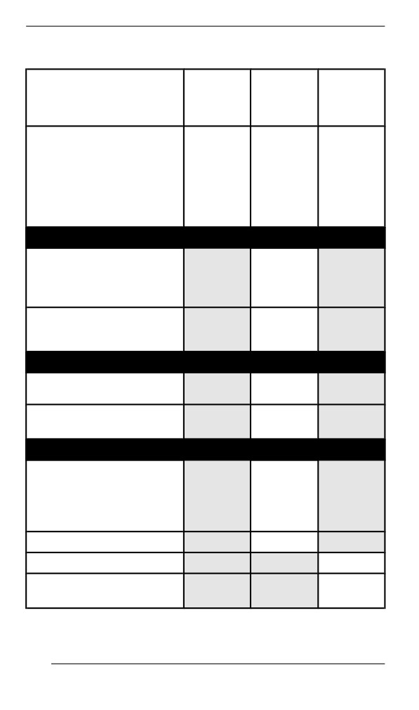
The maintenance chart indicates the items needing to be addressed
based on 2 criteria, whichever happens first:
- Calendar time
- Odometer reading.
Your driving habits determines the factors you shall adhere too. For
example:
- Someone who uses their vehicle every weekend trail riding would
most likely follow the odometer reading to determine the fre-
quency of his maintenance.
- Someone who uses their vehicle seldomly over the year or only on
a few occasions would follow the calendar time to determine the
frequency of his maintenance.
IMPORTANT: The following tables show the appropriate mainte-
nance application for the first 2 years. For subsequent years, repeat
the same pattern alternatively.
Maintenance Overview
Calendar
Trail/ Cross
Odometer
Time
Over/ Utility
Every
1500 km (1000 mi)
A+
Month
1 Year
3000 km (2000 mi)
A
Every
4500 km (3000 mi)
A+
Month
2 Years
6000 km (4000 mi)
A and B
159
MAINTENANCE SCHEDULE
600 EFI Engine
TRAIL /
CROSSOVER
A+
A
B
/ UTILITY
Every
Every 2
A=Adjust
Every
month
years
C=Clean
year
or
or
I=Inspect
or
1500
6000
L=Lubricate
3000 km
km
km
R=Replace
(2000
(1000
(4000
T=Torque
mi)
mi)
mi)
Air and Fuel Delivery
Fuel components (fuel
cap, hoses, clamps and
I
tank fixation) and
function
R
In-line fuel filter
Every 5
years
Body and Chassis
Body panels and
I, T
hardware
Pivots, latches, hinges
L
and key barrels
Engine and Cooling
Engine cooling
components (coolant
concentration, coolant
I, A
level, hose condition,
clamps, leaks)
Oil pump cable
A
Engine rubber mounts
I
Rewind starter (manual
C, L
start models)
160
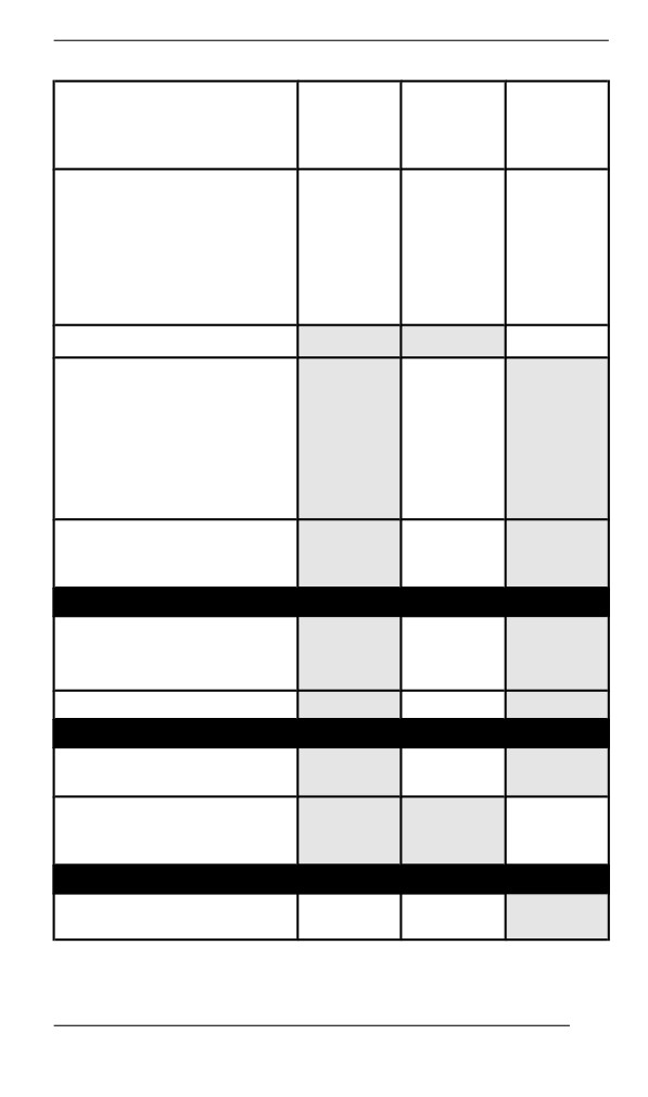
MAINTENANCE SCHEDULE
TRAIL /
CROSSOVER
A+
A
B
/ UTILITY
Every
Every 2
A=Adjust
Every
month
years
C=Clean
year
or
or
I=Inspect
or
1500
6000
L=Lubricate
3000 km
km
km
R=Replace
(2000
(1000
(4000
T=Torque
mi)
mi)
mi)
Spark plugs
R
I, C
Every 3
years
Oil injection pump
or
strainer
10 000
km
(6000
mi)
R
Engine coolant
Every 5
years
Exhaust and Emissions
Exhaust components
(gaskets, pipes, muffler
I
condition, leaks)
Exhaust manifold
T
Brake
Brake components and
I, L
function
R
Brake fluid
Every
2
years
Drive
Chaincase drive chain
A
A
tension
161
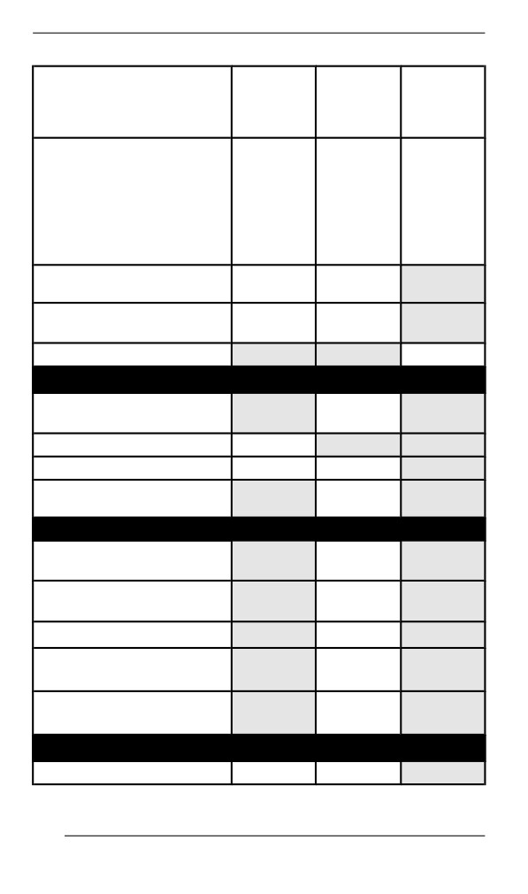
MAINTENANCE SCHEDULE
TRAIL /
CROSSOVER
A+
A
B
/ UTILITY
Every
Every 2
A=Adjust
Every
month
years
C=Clean
year
or
or
I=Inspect
or
1500
6000
L=Lubricate
3000 km
km
km
R=Replace
(2000
(1000
(4000
T=Torque
mi)
mi)
mi)
Gearbox / chaincase oil
I
I
level
Track alignment and
A
A
tension
Gearbox / chaincase oil
R
Continuously Variable Transmission (CVT)
CVT components and
I,
C, L
function
CVT drive belt condition
I
CVT drive belt tension
A
A
Drive pulley retaining
T
screw
Electrical
Battery connections and
I
condition
Electrical harness
I
routing
Headlight aim
A
Modules and applicable
I
software updates
Operation of control
I
switches and lighting
Steering and Controls
Ski runners
I
I
162
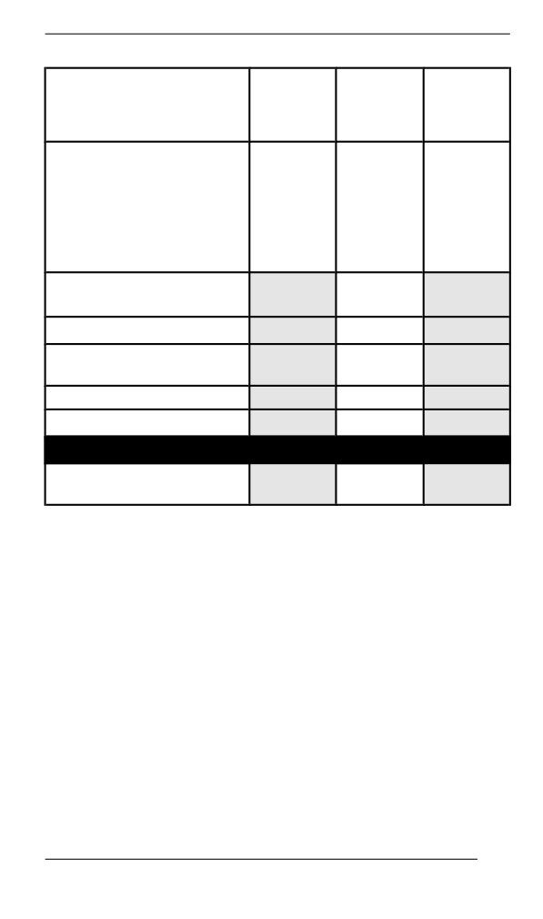
MAINTENANCE SCHEDULE
TRAIL /
CROSSOVER
A+
A
B
/ UTILITY
Every
Every 2
A=Adjust
Every
month
years
C=Clean
year
or
or
I=Inspect
or
1500
6000
L=Lubricate
3000 km
km
km
R=Replace
(2000
(1000
(4000
T=Torque
mi)
mi)
mi)
Gearbox position lever
I, A
operation
Steering alignment
I, A
Steering components
I
and function
Throttle cable
A
Throttle operation
I
Suspension
Suspension components
I, L
and function
163
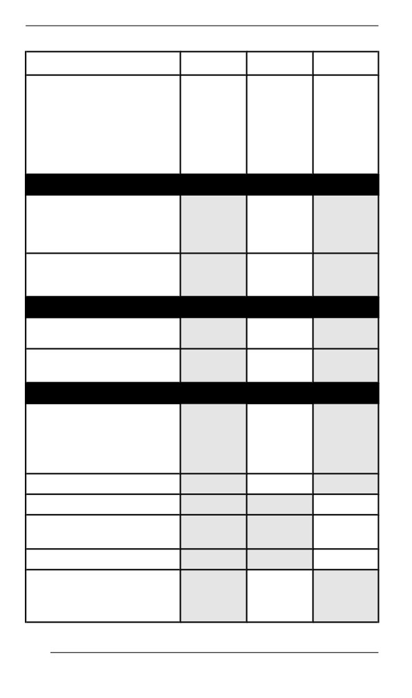
MAINTENANCE SCHEDULE
DEEP SNOW
A+
A
B
Every 2
A=Adjust
Every
Every
years
C=Clean
month
year
or
I=Inspect
or
or
6000
L=Lubricate
1500 km
3000 km
km
R=Replace
(1000
(2000
(4000
T=Torque
mi)
mi)
mi)
Air and Fuel Delivery
Fuel components (fuel
cap, hoses, clamps and
I
tank fixation) and
function
R
In-line fuel filter
Every 5
years
Body and Chassis
Body panels and
I, T
hardware
Pivots, latches, hinges
L
and key barrels
Engine and Cooling
Engine cooling
components (coolant
concentration, coolant
I, A
level, hose condition,
clamps, leaks)
Oil pump cable
A
Engine rubber mounts
I
Rewind starter (manual
C, L
start models)
Spark plugs
R
I, C
Oil injection pump
Every
3
strainer
years
or
164
MAINTENANCE SCHEDULE
DEEP SNOW
A+
A
B
Every 2
A=Adjust
Every
Every
years
C=Clean
month
year
or
I=Inspect
or
or
6000
L=Lubricate
1500 km
3000 km
km
R=Replace
(1000
(2000
(4000
T=Torque
mi)
mi)
mi)
10 000
km
(6000
mi)
R
Engine coolant
Every 5
years
Exhaust and Emissions
Exhaust components
(gaskets, pipes, muffler
I
condition, leaks)
Exhaust manifold
T
Brake
Brake components and
I, L
function
R
Brake fluid
Every
2
years
Drive
A
After the
first
75 km
(50 mi)
then
Chaincase drive chain
every
A
tension
500 km
(300 mi),
up to
then
every
165
MAINTENANCE SCHEDULE
DEEP SNOW
A+
A
B
Every 2
A=Adjust
Every
Every
years
C=Clean
month
year
or
I=Inspect
or
or
6000
L=Lubricate
1500 km
3000 km
km
R=Replace
(1000
(2000
(4000
T=Torque
mi)
mi)
mi)
1500 km
(1000
mi)
Gearbox / chaincase oil
I
level
A
After the
first
75 km
(50 mi)
then
every
Track alignment and
500 km
A
tension
(300 mi),
up to
then
every
1500 km
(1000
mi)
Gearbox / chaincase oil
R
Continuously Variable Transmission (CVT)
CVT components and
I, C, L
function
CVT drive belt condition
I
CVT drive belt tension
A
A
Drive pulley retaining
T
screw
Electrical
166
MAINTENANCE SCHEDULE
DEEP SNOW
A+
A
B
Every 2
A=Adjust
Every
Every
years
C=Clean
month
year
or
I=Inspect
or
or
6000
L=Lubricate
1500 km
3000 km
km
R=Replace
(1000
(2000
(4000
T=Torque
mi)
mi)
mi)
Battery connections and
I
condition
Electrical harness
I
routing
Headlight aim
A
Modules and applicable
I
software updates
Operation of control
I
switches and lighting
Steering and Controls
Ski runners
I
Gearbox position lever
I, A
operation
Steering alignment
I, A
Steering components
I
and function
Throttle cable
A
Throttle operation
I
Suspension
Suspension components
I, L
and function
167
MAINTENANCE PROCEDURES
This section includes instructions for basic maintenance procedures.
WARNING
Turn off the engine, remove tether cord cap and follow these
maintenance procedures when performing maintenance. If you
do not follow proper maintenance procedures you can be in-
jured by hot parts, moving parts, electricity, chemicals or other
hazards.
WARNING
Should removal of a locking device be required (e.g. lock tabs,
self-locking fasteners, etc.) when undergoing disassembly/as-
sembly, always replace with a new one.
Engiine Coolant
WARNING
Never open coolant tank cap when engine is hot.
Engine Coolant Level Verification
Open the RH side panel, see Body and Seat.
Check coolant level at room temperature. Liquid should be at cold lev-
el line of coolant tank.
NOTE:
When checking level at low temperature it may be slightly lower than
the mark.
If additional coolant is necessary or if entire system has to be refilled,
refer to an authorized BRP snowmobile dealer, repair shop or person
of your own choosing.
168
MAINTENANCE PROCEDURES
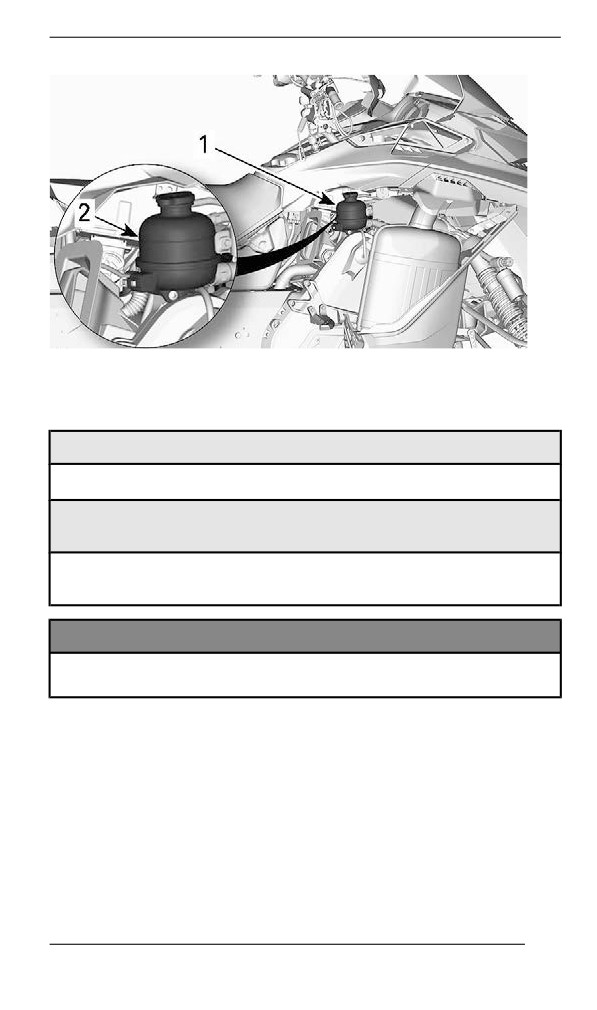
1. Coolant reservoir
2. COLD line
Recommended Engine Coolant
RECOMMENDED COOLANT
XPS Extended life pre-mixed coolant
IF THE RECOMMENDED XPS COOLANT IS NOT
AVAILABLE
Distilled water and antifreeze solution (50% distilled water, 50%
antifreeze)
NOTICE
Always use ethylene-glycol antifreeze containing corrosion in-
hibitors specifically for internal combustion aluminum engines.
Exhaust System
Exhaust System Verification
The muffler tail pipe should be centered with the exit hole in the bottom
pan. Exhaust system must be free of rust or leaks. Make sure that all
parts are securely in place.
Check retaining springs and heat shields condition and replace if
necessary.
169
MAINTENANCE PROCEDURES
The exhaust system is designed to reduce noise and to improve the
total performance of the engine. Modification may be in violation of lo-
cal laws.
NOTICE
If any exhaust system component is removed, modified or dam-
aged, severe engine damage may result.
Spark Pllugs
Spark plugs inspection or replacement may be performed by an au-
thorized BRP snowmobile dealer, repair shop, or person of your own
choosing. Spark plugs inspection or replacement requires an in-depth
technical knowledge. Though not required, it is recommended that an
authorized BRP snowmobile dealer performs spark plugs inspection
or replacement.
Brake Flluiid
Brake Fluid Level Verification
NOTICE
Vehicle must be on a level surface before checking any fluid
levels.
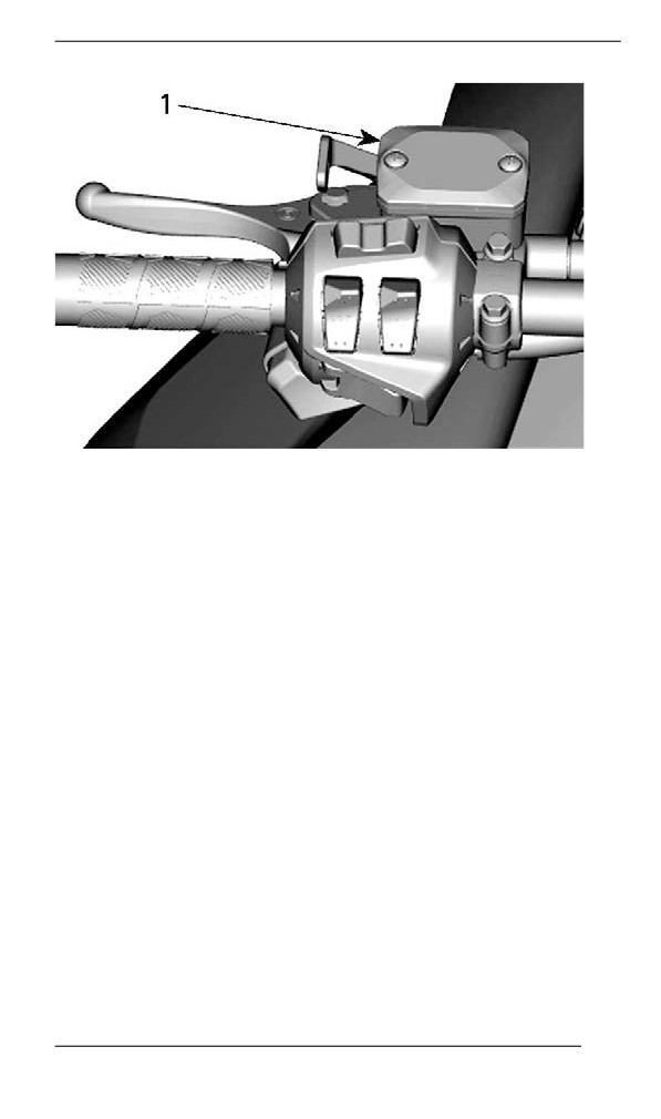
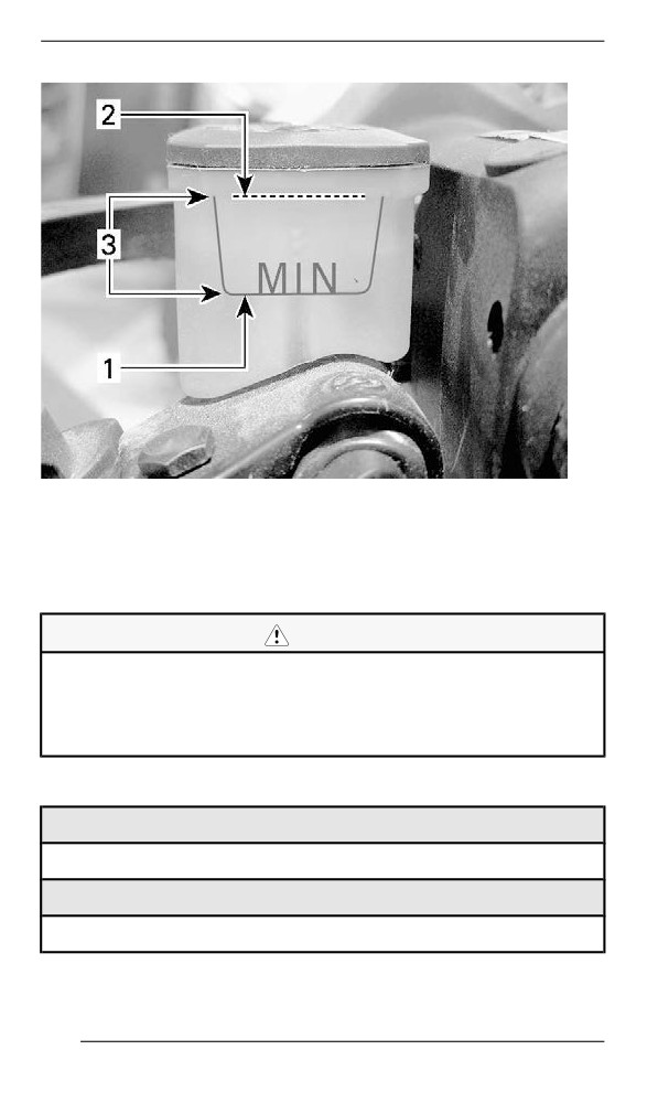
Check brake fluid (DOT 4) in reservoir for proper level. Add fluid (DOT
4) as required.
170
MAINTENANCE PROCEDURES
TYPICAL
1. Brake fluid reservoir
171
MAINTENANCE PROCEDURES
TYPICAL
1. Minimum
2. Maximum
3. Operating range
CAUTION
Avoid getting brake fluid on skin or eyes - it may cause severe
burns. In case of contact with the skin, wash thoroughly. In
case of contact with the eyes, immediately rinse with plenty of
water for at least 10 minutes and then consult a doctor
immediately.
Recommended Brake Fluid
Recommended Brake Fluid
XPS DOT 4 Brake Fluid
Alternative or if not available
DOT 4 Brake Fluid
172
MAINTENANCE PROCEDURES
Use only DOT 4 brake fluid from a sealed container. An opened con-
tainer may be contaminated or may have absorbed moisture from the
air.
WARNING
Use only DOT 4 brake fluid from a sealed container. To avoid
serious damage to the braking system, do not use fluids other
than the recommended one, nor mix different fluids for topping
up.
Chaincase Oiil
Recommended Chaincase Oil
Recommended Chaincase Oil
XPS Synthetic chaincase oil
Alternative or if not available
75W140 gear oil that meets the API GL-5 specification
NOTICE
If the recommended XPS chaincase oil is not available, use a
75W140 gear oil that meets the API GL-5 specification. The
chaincase of this snowmobile has been developed and vali-
dated using the XPS™ Synthetic chaincase oil. BRP strongly
recommends the use of its XPS Synthetic chaincase oil at all
times. Damages caused by oil which is not suitable for the
chaincase will not be covered by the BRP limited warranty.
Verifying the Chaincase Oil Level
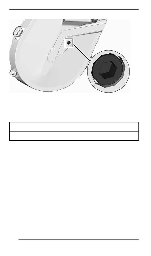
With the vehicle on a level surface, check the oil level by removing the
check plug.
173
MAINTENANCE PROCEDURES
CHECK PLUG
Oil level must reach the threaded hole.
If level is correct, reinstall check plug and tighten to the specified
torque.
Tightening Torque
Check plug
6 ± 1 Nm (53 ± 9 lbf-in)
If level is insufficient, refer to Chaincase Filling Procedure.
Replacing the Chaincase Oil
Draining the Chaincase Oill
1. Place the vehicle on a level surface.
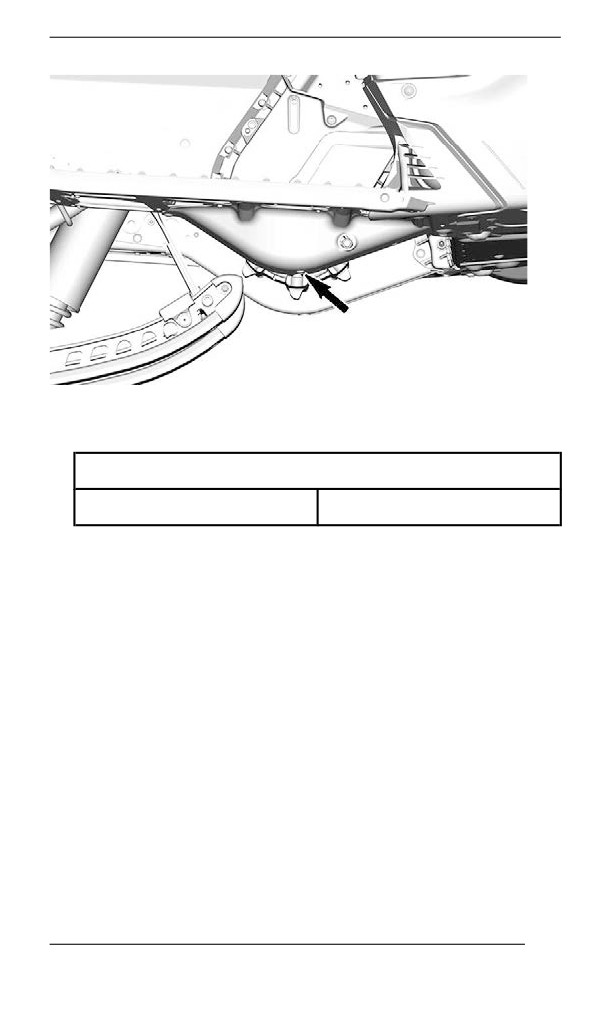
2. Place a drain pan under the chaincase drain plug area.
3. Remove filler cap.
4. Remove the drain plug located at the bottom of the chaincase.
174
MAINTENANCE PROCEDURES
5. Wait a while to allow all oil to drain out of the chaincase.
6. Install drain plug and tighten to specification.
Tightening Torque
Chaincase drain plug
6 ± 1 Nm (53 ± 9 lbf-in)
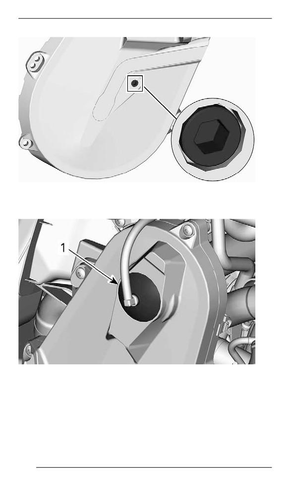
Fillliing the Chaiincase
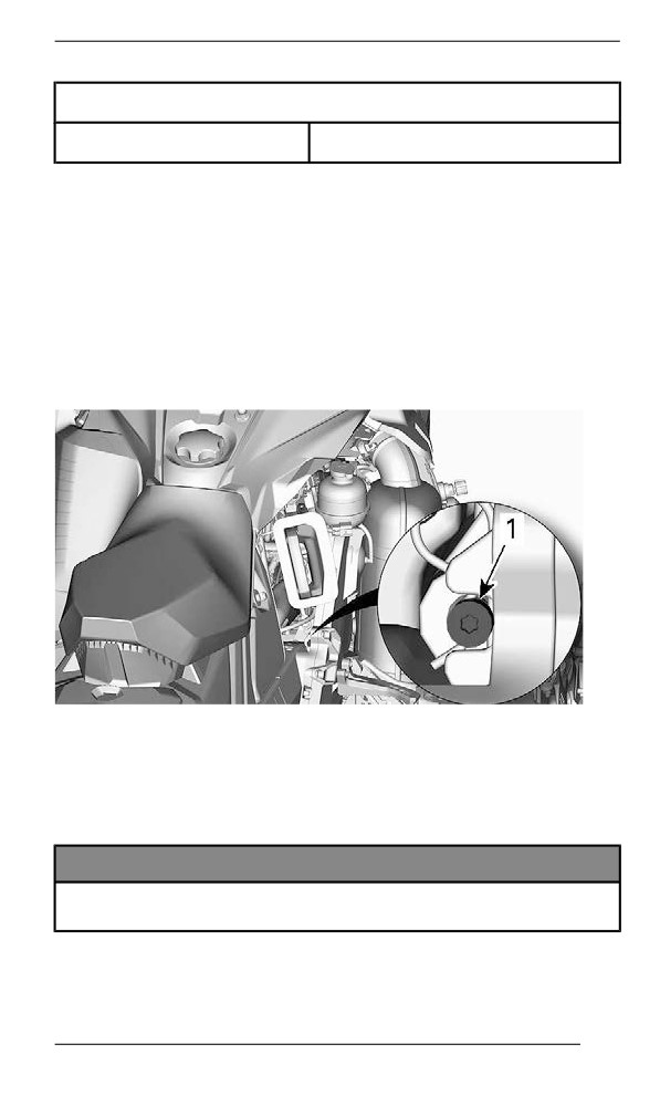
1. Open the RH side panel. Refer to Equipment.
2. Remove the check plug.
175
MAINTENANCE PROCEDURES
CHECK PLUG
3. Remove the filler cap.
TYPICAL - TOP OF CHAINCASE
1. Filler cap
4. Pour recommended oil in the filler hole until oil comes out by the
check plug hole.
5. Reinstall check plug and tighten to specification.
176
MAINTENANCE PROCEDURES
Tightening Torque
Check plug
6 ± 1 Nm (53 ± 9 lbf-in)
Reinstall the filler cap.
Driive Chain
Access to Chaincase
Open RH side panel, refer to Equipment.
Drive Chain Adjustment
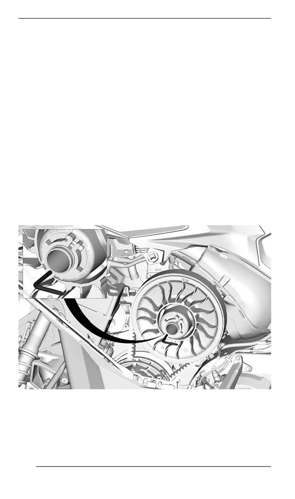
Using the Torx end of the driven pulley expander, GENTLY turn ten-
sioner clockwise to eliminate the play.
TYPICAL
Do not force the tensioner in.
NOTE:
Do not remove the hair cotter pin.
NOTICE
Overtightening the drive chain could result in severe damage to
the chaincase components.
177
MAINTENANCE PROCEDURES
Drive Belt
Drive Belt Inspection
Remove the drive belt guard. Refer to the procedure in Equipment.
Inspect belt for cracks, fraying or abnormal wear (uneven wear, wear
on one side, missing cogs, cracked fabric). If abnormal wear is noted,
probable cause could be pulley misalignment, excessive RPM with
frozen track, fast starts without warm-up period, burred or rusty
sheave, oil on belt or distorted spare belt. Contact an authorized BRP
snowmobile dealer.
Replacing the Drive Belt
Removiing the Driive Belt
1. Remove the tether cord cap from engine cut-off switch.
2. Remove the LH side panel.
3. Remove the drive belt guard. Refer to Removing the Drive Belt
Guard.
4. Insert the driven pulley expander provided, in the threaded hole on
the adjuster hub as shown.
TYPICAL - PULLEY EXPANDER INSTALLED ON ADJUSTER
HUB
5. Open the driven pulley by screwing the tool in.
6. Remove the drive belt by slipping it over the edge of the driven pul-
ley, then over the drive pulley.
178
MAINTENANCE PROCEDURES
Installliing the Drive Belt
The driven pulley must be expanded. Refer to Removing the Drive
Belt.
1. Slip the belt over the drive pulley, then over the driven pulley.
NOTICE
Do not force or use tools to pry the belt into place, as this could
cut or break the cords in the belt.
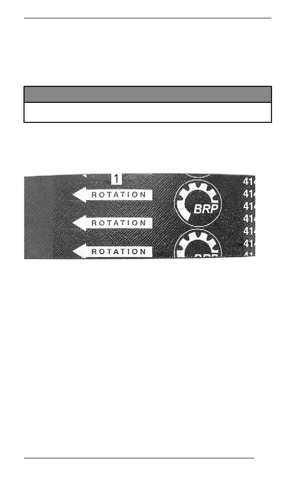
NOTE:
The maximum drive belt life span is obtained when belt is installed
with arrows in the direction of rotation.
1. To be pointed in the direction of rotation
2. Unscrew and remove the driven pulley expander from the pulley.
3. Rotate the driven pulley several times to properly set the belt be-
tween the sheaves.
4. If a new belt was installed, an adjustment will be required for the
proper belt height. Refer to Adjusting the Drive Belt Height.
5. Install belt guard.
6. Close side panel.
Adjusting the Drive Belt Height
Remove the tether cord cap from engine cut-off switch.
Remove the LH side panel.
Remove the drive belt guard.
The drive belt height must be checked every time a new drive belt is
installed and as part of the pre-ride inspection.
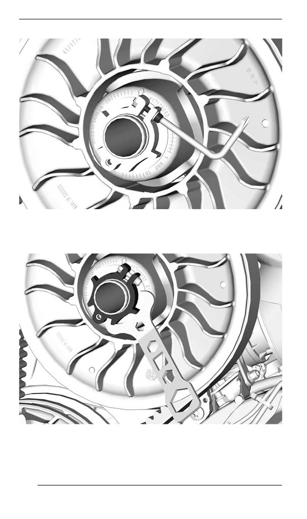
1. Loosen the clamping bolt.
179
MAINTENANCE PROCEDURES
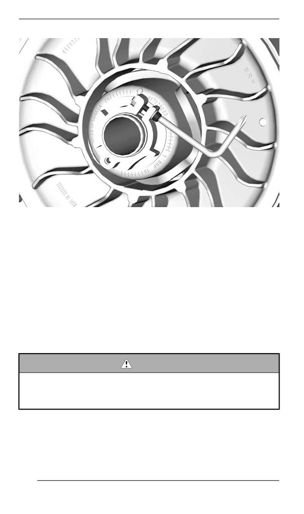
2. Using the suspension adjustment tool provided in the tool kit, turn
the adjustment ring 1/4 turn at a time then rotate the driven pulley
to properly set the belt between the pulley sheaves.
180
MAINTENANCE PROCEDURES
NOTE:
The adjustment ring has left hand treads.
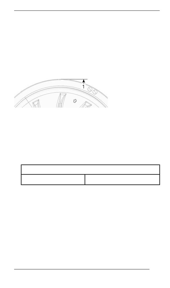
Repeat step 4 until the drive belt outer surface is even with the driv-
en pulley edge.
600 EFI - PRELIMINARY SETTING
1. Drive belt outer surface is even with the driven pulley edge
NOTE:
Turning the ring counterclockwise lowers the drive belt in the pulley.
Turning the ring clockwise raises the drive belt in the pulley.
3. Tighten the adjustment ring clamping screw.
TIGHTENING TORQUE
Clamping bolt
5.5 ± 0.5 Nm (49 ± 4 lbf-in)
181
MAINTENANCE PROCEDURES
4. Install belt guard, refer to Installing the Drive Belt Guard.
5. Install LH side panel.
6. Start engine and check if vehicle creeps.
7. If vehicle does not creep, adjustment is complete.
8. If vehicle creeps, check the drive belt deflection.
Reverse Actiivatiion (iif equipped)
Reverse may not activate or may be harder to activate if the belt is
positioned too high in the driven pulley. If reverse activation does not
work properly, ensure the drive belt is properly adjusted.
Adjust the drive belt lower in the driven pulley if needed.
Track
Track Condition
WARNING
Remove tether cord cap from engine cut-off switch before per-
forming any maintenance or adjustment, unless otherwise
specified. Vehicle must be parked in a safe place, away from
the trail.
Remove tether cord cap from engine cut-off switch.
Lift the rear of the snowmobile and support it with a wide-base snow-
mobile mechanical stand with a rear deflector panel. With the engine
182
MAINTENANCE PROCEDURES
off, rotate the track by hand, and inspect condition. If worn or cut, or if
track fibers are exposed, or if missing or defective inserts or guides
are noted; contact an authorized BRP snowmobile dealer.
Snowmobiles Equipped with Traction Enhancing Products
If your snowmobile is equipped with a BRP approved studded track,
PROCEED WITH A VISUAL INSPECTION OF YOUR TRACK BE-
FORE EACH USE.
Look for any defects, such as:
- Perforations in the track
- Tears in the track (particularly around traction holes on studded
tracks)
- Lugs that are broken or torn off, exposing portions of rods
- Delamination of the rubber
- Broken rods
- Broken studs (studded tracks)
- Bent studs (studded tracks)
- Missing studs
- Studs that are torn off the track
- Missing track guide(s)
- Also, ensure that studs nut are tighten to the recommended
torque.
On approved studded tracks, replace broken or damaged studs imme-
diately. If your track shows signs of deterioration, it must be replaced
immediately. When in doubt, ask your dealer.
WARNING
Riding with a damaged track or studs could lead to a loss of
control.
For complete information on traction enhancing products, refer to
TRACTION ENHANCING PRODUCTS in SAFETY INFORMATION at
the beginning of this Operator's Guide.
Track Tension and Alignment
NOTE:
Track tension and alignment are interrelated. Do not adjust one with-
out the other.
183
MAINTENANCE PROCEDURES
WARNING
To prevent serious injury to individuals near the snowmobile:
– NEVER stand behind or near a moving track.
– Always use a wide-base snowmobile stand with a rear de-
flector panel if it is necessary to rotate track.
– When the track is raised off the ground, only run it at the low-
est possible speed.
Centrifugal force could cause debris, damaged or loose studs,
pieces of torn track, or an entire severed track to be violently
thrown backwards out of the tunnel with tremendous force, pos-
sibly resulting in the loss of a leg or other serious injury.
Veriifyiing the Track Tension
NOTE:
Ride the snowmobile in snow about 15 to 20 minutes prior to adjusting
track tension.
1. Remove tether cord cap from engine cut-off switch.
2. Lift rear of vehicle and support it off the ground.
CAUTION
Use proper lifting techniques, notably using your legs force. Do
not attempt to lift the rear of vehicle if it is above your limits.
3. Allow rear suspension to fully extend.
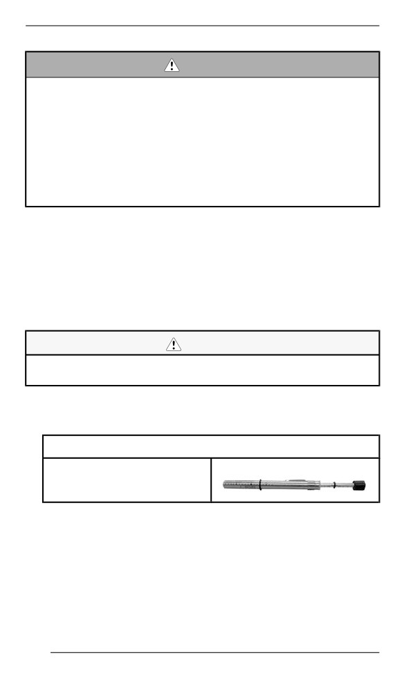
4. Prepare the tensiometer.
Service tool
Tensiometer (P/N 414348200)
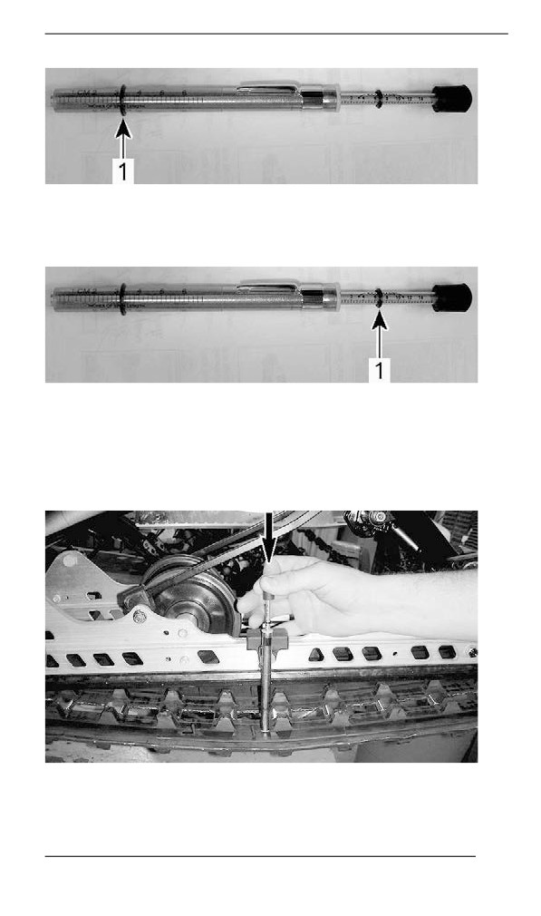
1. Set the bottom O-ring as per the Track Deflection from the ap-
plicable vehicle in the Technical Specifications table.
184
MAINTENANCE PROCEDURES
1. Bottom O-ring
2. Place the upper O-ring to 0 kgf (0 lbf).
1. Upper O-ring
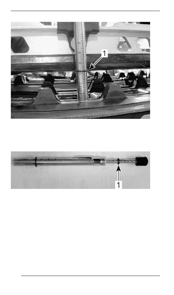
5. Position the tensiometer on track, halfway between front and rear
idler wheels.
6. Push the tensiometer downwards until bottom O-ring (deflection
set earlier) be aligned with the bottom of slider shoe.
TYPICAL
185
MAINTENANCE PROCEDURES
TYPICAL
1. Deflection O-ring aligned with slider shoe
7. Read load recorded by the upper O-ring on the tensiometer.
TYPICAL - LOAD READING
1. Upper O-ring
8. Load reading must be as per the track deflection in the Technical
Specifications.
9. If load reading is not in accordance with the specification, adjust
track tension. Refer to Track Tension Adjustment.
Adjjusting the Track Tensiion - EasyRide-F
Suspensiion
1. Remove the tether cord cap from engine cut-off switch.
2. Lift rear of vehicle and support it off the ground.
186
MAINTENANCE PROCEDURES
CAUTION
Use proper lifting techniques, notably using your legs force. Do
not attempt to lift the rear of vehicle if it is above your limits.
3. Allow rear suspension to fully extend.
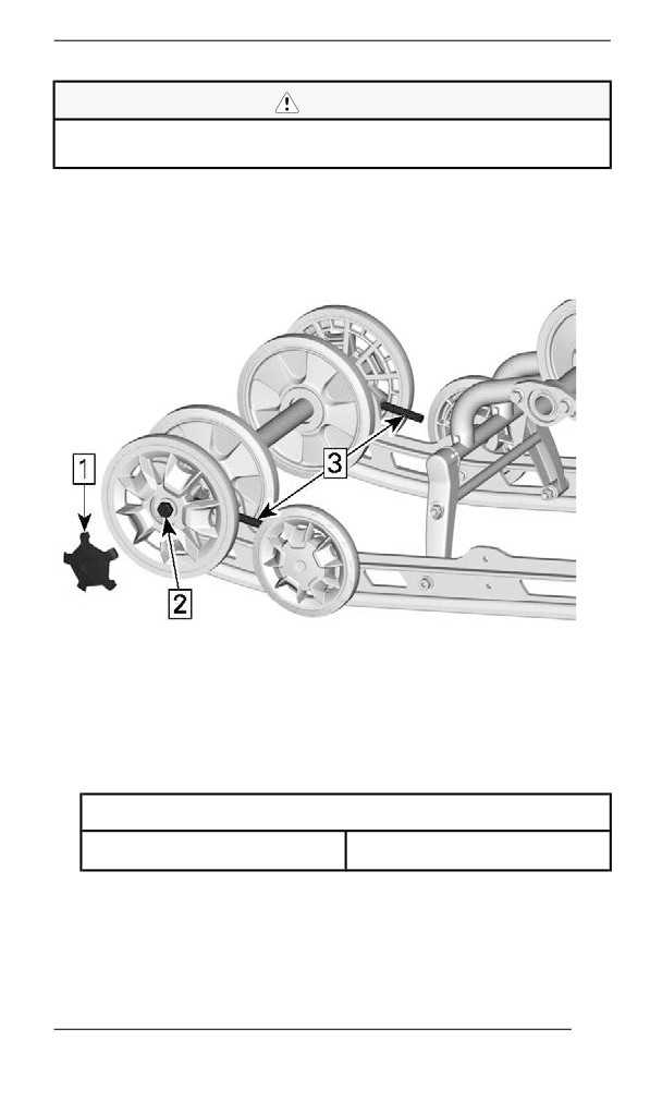
4. Remove rear wheel caps.
5. Loosen the rear idler wheels retaining screws.
6. Tighten or loosen both adjustment screws to increase or decrease
track tension.
EASYRIDE-F
1. Remove cap
2. Loosen the idler wheel screw
3. Loosen or tighten adjustment screws
7. If correct tension is unattainable, contact an authorized BRP snow-
mobile dealer.
8. Retighten idler wheels retaining screws to specification.
TIGHTENING TORQUE
Idler wheel screw
48 ± 6 Nm (35 ± 4 lbf-ft)
9. Check track alignment as described below.
187
MAINTENANCE PROCEDURES
Aliigniing the Track
WARNING
Before checking track alignment, ensure that the track is free of
all particles which could be thrown out while track is rotating.
Keep hands, tools, feet and clothing clear of track. Always lift
the snowmobile on a wide-base stand with a rear deflector pan-
el. Ensure no one is standing in close proximity to the snowmo-
bile, especially at the rear of the track. Never rotate track at
high speed.
Centrifugal force could cause debris, damaged or loose studs,
pieces of torn track, or an entire severed track to be violently
thrown backwards out of the tunnel with tremendous force.
1. Lift rear of vehicle and support it off the ground.
CAUTION
Use proper lifting techniques, notably by using the force of your
legs . Do not attempt to lift the rear of vehicle if it is above your
limits.
2. Start engine and accelerate slightly so that track slowly turns. This
must be done in a short period of time (15 to 20 seconds).
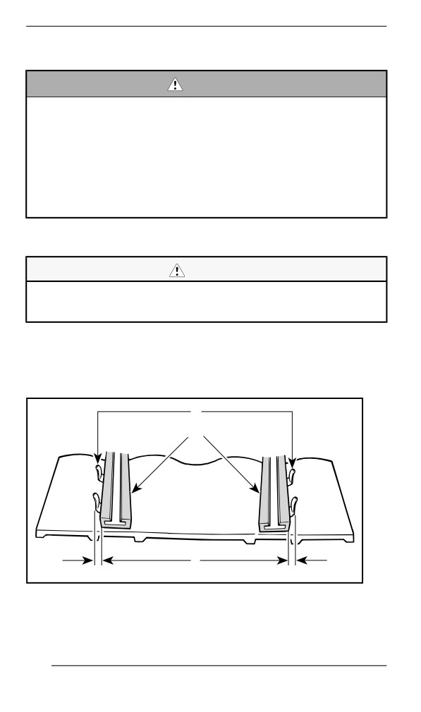
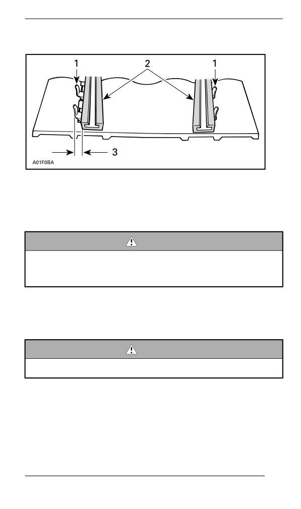
3. Check that the track is well centered; equal distance on both sides
between edges of track guides and slider shoes.
1
2
3
A01F05A
1. Guides
2. Slider shoes
3. Equal distance
188
MAINTENANCE PROCEDURES
4. To correct track alignment:
1. Guides
2. Slider shoes
3. Tighten on this side
1. Stop engine.
2. Remove tether cord cap from engine cut-off switch.
WARNING
Remove tether cord cap from engine cut-off switch before per-
forming any maintenance or adjustment, unless otherwise
specified. Vehicle must be parked in a safe place, away from
the trail.
3. Loosen the rear axle nut.
4. Tighten adjustment screw on side where the slider shoe is the
farthest from the track insert guides.
5. Tighten the rear axle nut.
WARNING
Properly tighten wheel retaining bolt, otherwise wheel may
come off and cause track to “lock”.
6. Restart engine and rotate track slowly to recheck alignment.
7. Tighten the rear axle nut to specified torque.
189
MAINTENANCE PROCEDURES
Tightening Torque
Rear axle screw
48 ± 6 Nm (35 ± 4 lbf-ft)
8. Reposition snowmobile on the ground.
Suspensiion
Rear Suspension Condition
Visually inspect all suspension components including slider shoes,
springs, wheels, etc.
NOTE:
During normal driving, snow will act as a lubricant and coolant for the
slider shoes. Extensive riding on ice or sanded snow, will create ex-
cessive heat build-up and cause premature slider shoe wear.
Suspension Stopper Strap Condition
Inspect stopper straps for wear and cracks, bolt and nut for tightness.
If loose inspect holes for deformation. Replace as required. Tighten
nut to specification.
Tightening Torque
Stopper strap nut
11 ± 1 Nm (97 ± 9 lbf-in)
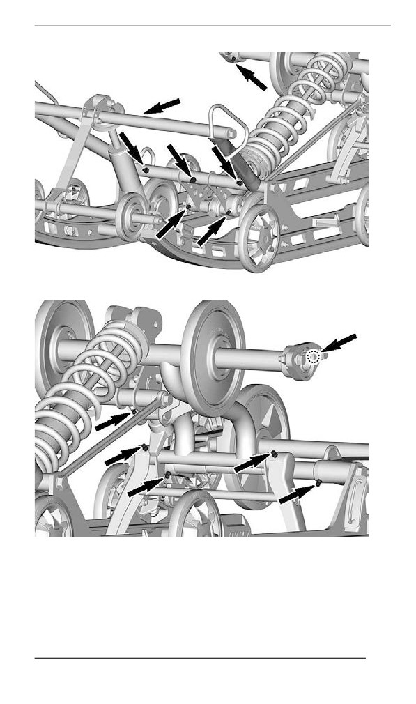
Suspension Lubrication – EasyRide
Lubricate the following suspension pivots at grease fittings. Refer to
Maintenance Schedule for maintenance frequency.
Suspension Grease
XPS Synthetic suspension grease
190
MAINTENANCE PROCEDURES
Steering and Front Suspension Condition
Visually inspect steering and front suspension for tightness of compo-
nents (steering arms, control arms and links, tie rods, ball joints, ski
bolts, ski legs, etc.). If necessary, contact an authorized BRP snowmo-
bile dealer.
191
MAINTENANCE PROCEDURES
Skiis
Wear and Condition of Skis and Runners
Check the condition of the skis and ski runner carbides. If worn, con-
tact an authorized BRP snowmobile dealer.
WARNING
Excessively worn skis and/or ski runners will adversely affect
snowmobile control.
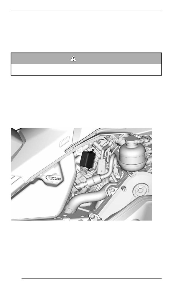
Fuses
Access to Fuse Block
Open RH side panel, refer to Body and Seat.
Fuses Location
600 EFI Engine
FUSE BOX
192
MAINTENANCE PROCEDURES
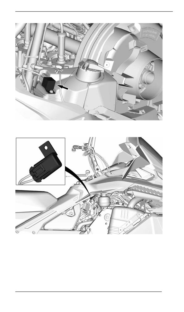
RADIATOR FAN RELAY
RADIATOR FAN FUSE
Refer to the Technical Specifications for fuse rate and configuration.
Fuse Inspection
Check fuse condition and replace it if necessary.
193
MAINTENANCE PROCEDURES
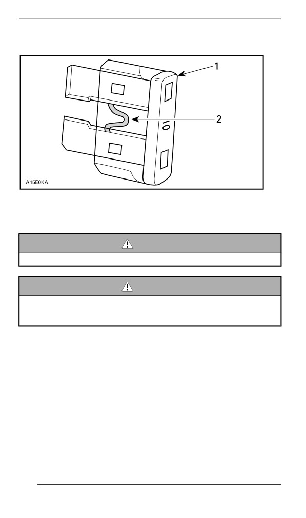
To remove fuse from holder, pull fuse out. Check if filament is melted.
1. Fuse
2. Check if melted
WARNING
Do not use a higher rated fuse.
WARNING
If fuse has burnt out, source of malfunction should be deter-
mined and corrected before restarting. See an authorized BRP
snowmobile dealer for servicing.
Headllights
Headlights Bulb Replacement
1. Remove the windshield. Refer to Removing the Windshield in Body
and Seat subsection.
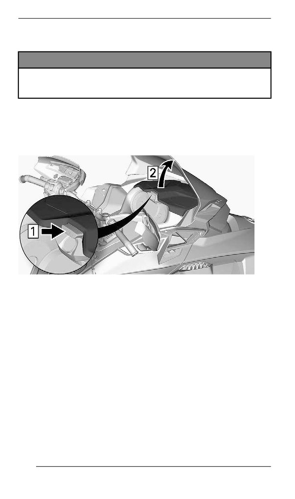
2. Open the storage compartment.
194
MAINTENANCE PROCEDURES
TYPICAL
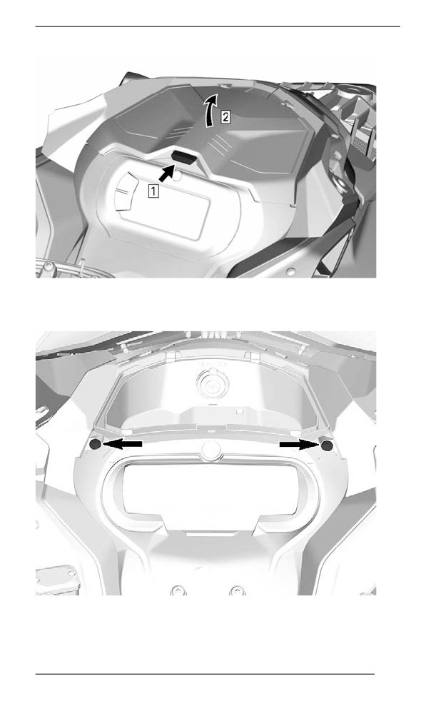
3. Remove the gauge support retaining screws.
4. Lift the front of the gauge support, then slide it forward to remove it.
195
MAINTENANCE PROCEDURES
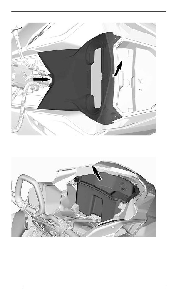
5. Set gauge support aside.
6. Remove the storage compartment.
7. Disconnect 12V power outlet connectors to remove (if equipped).
8. Disconnect bulb connector.
196
MAINTENANCE PROCEDURES
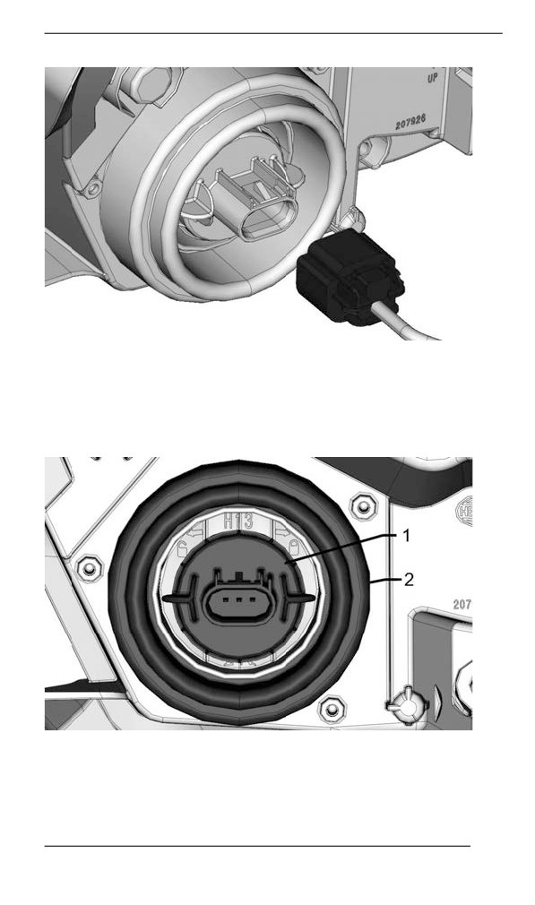
9. Unlock bulb by turning it counterclockwise.
10. Pull bulb out.
NOTE:
Ensure bulb seal stays in place.
1. Bulb
2. Bulb seal
197
MAINTENANCE PROCEDURES
Install a new bulb using the reverse of the removal procedure.
NOTICE
Never touch glass portion of an halogen bulb with bare fingers,
it shortens its operating life. If glass is touched, clean it with
isopropyl alcohol which will not leave a film on the bulb.
Check headlights operation.
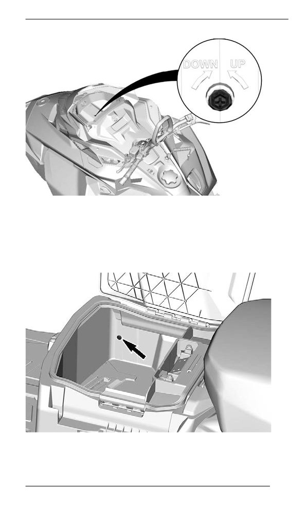
Headlights Beam Aiming
Open the storage compartment.
TYPICAL
Turn the adjustment screw to reach desired beam height.
198
MAINTENANCE PROCEDURES
Battery
Removing the Battery
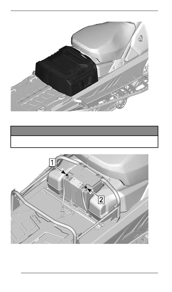
1. Remove the passenger seat and backrest, if equipped.
2. Open the cargo box, remove the battery cover and all mounting
screws.
LH SIDE SCREW SHOWN
3. Remove the cargo box.
199
MAINTENANCE PROCEDURES
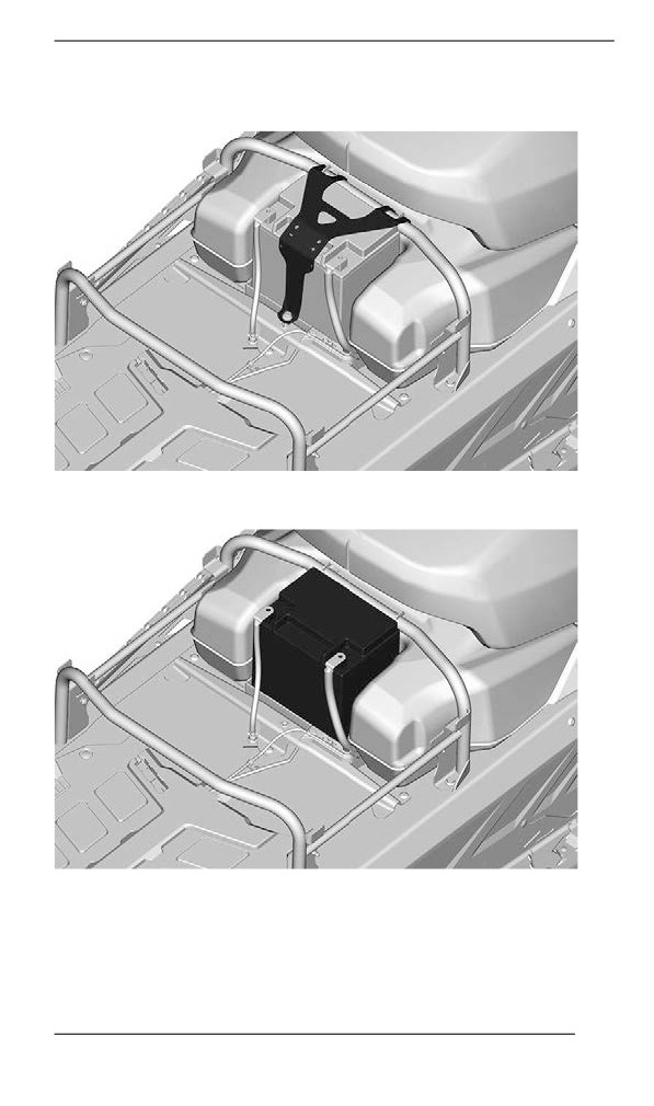
4. Disconnect the negative terminal first, then the positive terminal.
NOTICE
Battery BLACK ( – ) cable must always be disconnected first
and connected last.
1. Disconnect negative
2. Disconnect positive
200
MAINTENANCE PROCEDURES
5. Remove the battery hold down bracket.
6. Remove the battery.
Installing the Battery
The installation is the reverse of the removal procedure. However, pay
attention to the following details.
201
MAINTENANCE PROCEDURES
TIGHTENING TORQUE
Battery terminals (positive and
10 ± 2 Nm (89 ± 18 lbf-in)
negative)
Battery hold down bracket
5 ± 0.5 Nm (44 ± 4 lbf-in)
Battery cover retaining screws
5±0.5Nm(44±4lbf-in)
202
VEHICLE CARE
Post-Operatiion Care
Remove snow and ice from rear suspension, track, front suspension,
steering mechanism and skis.
WARNING
Make sure D.E.S.S. key is removed from D.E.S.S. post before
standing in front the vehicle, getting close to the track or rear
suspension components.
Always cover your snowmobile when leaving it outside overnight or
during extended periods of inactivity. This will protect it from frost and
snow as well as help retain its appearance.
Vehicle Cleaning and Protectiion
Wash snowmobile using water mixed with a mild detergent.
Use only microfiber cloths or an equivalent.
NOTICE
Never use a high pressure washer to clean the vehicle. Use low
pressure only, like a garden hose.
Non Compatible Cleaning Products
Material Type
Non-Compatible Cleaning Products
BRAKE AND PARTS CLEANER
All plastics, vinyls,
OR
painted steel and
ANY PETROLEUM BASE CLEANING
aluminium
PRODUCTS
Compatible Cleaning Products
Material Type
Cleaning Product
All plastics, vinyls,
Automotive type soap with water
painted steel and
XPS Spray Cleaner and Polish
aluminium.
XPS All Purpose Cleaner
For more information and products, Visit the XPS Products website at
203
STORAGE
During summer, or when a snowmobile is not in use for more than
three months, proper storage is necessary.
Storage
Clean the vehicle
Add fuel stabilizer to fuel following the product manufacturer
recommendations.
Run the engine after adding the product to the fuel
Lubricate engine. Refer to Engine Storage Procedure in this
section.
Lubricate brake lever pivot
Lubricate rear suspension
Charge battery monthly to keep it fully charged during storage (if
equipped)
Block muffler outlet with rags
Lift rear of vehicle until track is clear of the ground. Do not release
track tension
CAUTION
Use appropriate lifting device or have assistance to share lifting
stress. If a lifting device is not used, use proper lifting techni-
ques, notably using your legs force. Do not attempt to lift the
rear of vehicle if it is above your limits.
NOTICE
The snowmobile has to be stored in a cool and dry place and
covered with an opaque but ventilated tarpaulin. This will pre-
vent sun rays and grime from affecting plastic components and
vehicle finish.
NOTICE
Fuel stabilizer should be added prior to engine lubrication to
prevent the loss of the chemical properties of fuel and protect
the fuel system against varnish deposits.
204
STORAGE
Engine Storage Procedure
The engine has to be properly lubricated at storage for internal parts
protection.
600 EFI Engine
1. Place the vehicle in a well ventilated area.
2. Open the RH side panel. Refer to Controls, Instruments and
Equipment.
3. Add Fuel stabilizer to fuel thank. Follow the manufacturer's
recommendations.
4. Start the engine and let idle until rear heat exchanger gets hot.
The rear heat exchanger can be reached from under the rear end
of the chassis.
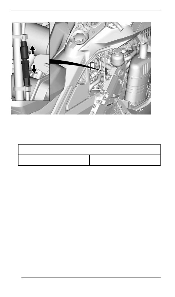
5. Pull on the oil pump cable - at the adjustment - until the exhaust
gas turns to darker smoke.
205
STORAGE
6. Remove the spark plugs and spray storage oil for 5 seconds in
each cylinder.
7. Spin the drive pulley for three complete revolutions by hand to dis-
tribute the storage oil to coat the cylinder walls.
8. Reinstall the spark plugs and tighten to specification.
Tightening torque
Spark plug
28 ± 2 Nm (21 ± 1 lbf-ft)
206
PRESEASON PREPARATION
Proper vehicle preparation is necessary when a vehicle has not been
used for more than three months.
Using the maintenance schedule, perform the items titled EVERY
YEAR AT PRESEASON.
Visit your authorized BRP snowmobile dealer for more information.
207
MAINTENANCE RECORDS
Send photocopy of maintenance record to BRP if needed.
Pre-delivery
Serial
Signature/Print:
number:
Mileage /
km:
Hours:
Date:
Dealer
no:
Notes:
Refer to vehicle Pre-Delivery Bulletin for detailed installation
procedures
208
MAINTENANCE RECORDS
First inspection
Mileage /
Signature/Print:
km:
Hours:
Date:
Dealer
no:
Notes:
For maintenance schedule refer to Maintenance Information
section of this operator's guide
Service
Mileage /
Signature/Print:
km:
Hours:
Date:
Dealer
no:
Notes:
For maintenance schedule refer to Maintenance Information
section of this operator's guide
209
MAINTENANCE RECORDS
Service
Mileage /
Signature/Print:
km:
Hours:
Date:
Dealer
no:
Notes:
For maintenance schedule refer to Maintenance Information
section of this operator's guide
Service
Mileage /
Signature/Print:
km:
Hours:
Date:
Dealer
no:
Notes:
For maintenance schedule refer to Maintenance Information
section of this operator's guide
210
MAINTENANCE RECORDS
Service
Mileage /
Signature/Print:
km:
Hours:
Date:
Dealer
no:
Notes:
For maintenance schedule refer to Maintenance Information
section of this operator's guide
Service
Mileage /
Signature/Print:
km:
Hours:
Date:
Dealer
no:
Notes:
For maintenance schedule refer to Maintenance Information
section of this operator's guide
211
MAINTENANCE RECORDS
Service
Mileage /
Signature/Print:
km:
Hours:
Date:
Dealer
no:
Notes:
For maintenance schedule refer to Maintenance Information
section of this operator's guide
Service
Mileage /
Signature/Print:
km:
Hours:
Date:
Dealer
no:
Notes:
For maintenance schedule refer to Maintenance Information
section of this operator's guide
212
MAINTENANCE RECORDS
Service
Mileage /
Signature/Print:
km:
Hours:
Date:
Dealer
no:
Notes:
For maintenance schedule refer to Maintenance Information
section of this operator's guide
Service
Mileage /
Signature/Print:
km:
Hours:
Date:
Dealer
no:
Notes:
For maintenance schedule refer to Maintenance Information
section of this operator's guide
213
MAINTENANCE RECORDS
Service
Mileage /
Signature/Print:
km:
Hours:
Date:
Dealer
no:
Notes:
For maintenance schedule refer to Maintenance Information
section of this operator's guide
Service
Mileage /
Signature/Print:
km:
Hours:
Date:
Dealer
no:
Notes:
For maintenance schedule refer to Maintenance Information
section of this operator's guide
214