Snowmobile Lynx 59 RANGER 600 EFI. OPERATOR’S GUIDE (2024) - page 2
PRE-RIDE INSPECTION
Pre-Ride Check Liist
ITEM
OPERATION
ü
BODY INCLUDING
SEAT, FOOTRESTS,
Check condition wear and remove
LIGHTS, AIR FILTER,
snow or ice .
CONTROLS AND
INSTRUMENTS
SKIS AND STEERING
Check for free movement and proper
ACTION
operation.
Check for proper operation and
SKI RUNNERS
abnormal wear.
FUEL
Check for proper level and no leaks.
INJECTION OIL (IF
Check for proper level and no leaks.
APPLICABLE)
COOLANT
Check for proper level and no leaks.
Check for cracks, fraying or abnormal
DRIVE BELT
wear and proper height.
THROTTLE LEVER
Check for proper operation.
BRAKE LEVER
Check for proper operation.
PARKING BRAKE,
Check for proper operation.
BRAKE
BRAKE FLUID
Check for proper level and no leaks.
STORAGE
Check for proper latching and no
COMPARTMENT
heavy or breakable objects.
Check condition and remove snow or
ice.
TRACK
For studded tracks, refer to Traction
Enhancing Products.
Check for proper operation and
SLIDER SHOES
abnormal wear.
SAFETY INFORMATION
75
PRE-RIDE INSPECTION
EMERGENCY ENGINE
STOP SWITCH AND
Check for proper action. Tether cord
ENGINE CUT-OFF
must be attached to operator clothing
SWITCH (TETHER
eyelet.
CORD CAP)
LIGHTS
Check for proper operation.
HORN BUTTON (IF
Check for proper operation.
EQUIPPED)
76
SAFETY INFORMATION
VEHICLE
INFORMATION
77
PRIMARY CONTROLS
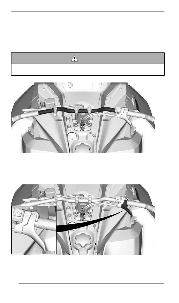
Handllebar
The handlebar controls the steering of the snowmobile. As the handle-
bar is rotated to right or left, the skis are turned right or left to steer the
snowmobile.
WARNING
Fast reverse while turning, could result in loss of stability and
control.
TYPICAL
Throttlle Lever
Throttle lever is located on the RH side of handlebar.
TYPICAL
78
PRIMARY CONTROLS
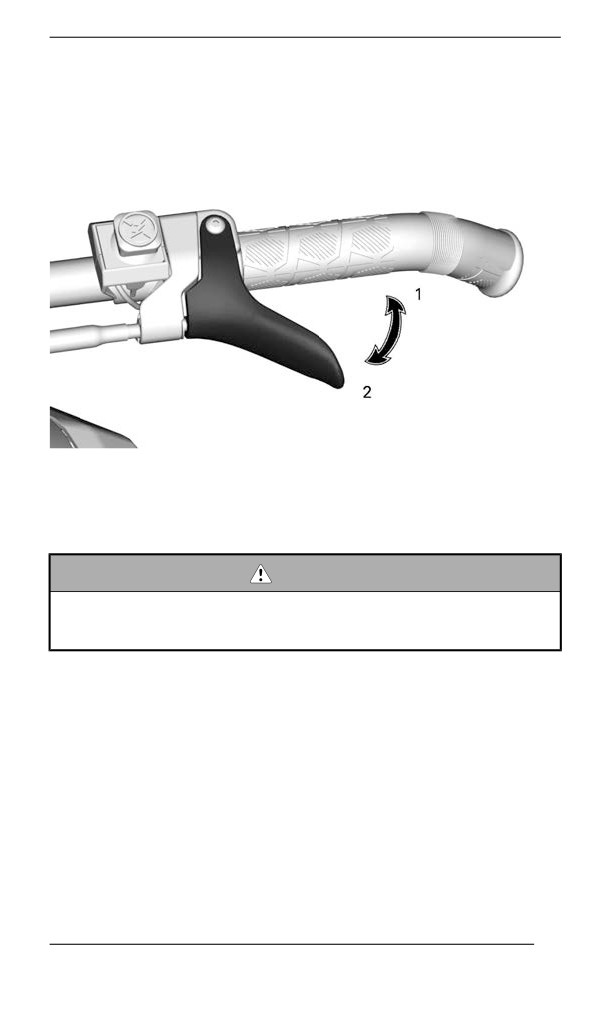
Designed to be thumb activated. When squeezed, it increases the en-
gine speed. When released, engine speed returns automatically to
idle.
CABLE THROTTLE LEVER
1. To accelerate
2. To decelerate
WARNING
Test the throttle lever operation each time before starting the
engine. The lever must return to the rest position once re-
leased. Otherwise, do not start engine.
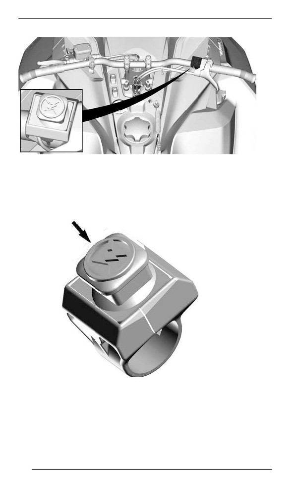
Emergency Engine Stop Switch
The emergency engine stop switch is located on the RH side of
handlebar.
79
PRIMARY CONTROLS
TYPICAL
To stop the engine in an emergency, push the switch down in OFF po-
sition and simultaneously apply the brake.
OFF POSITION
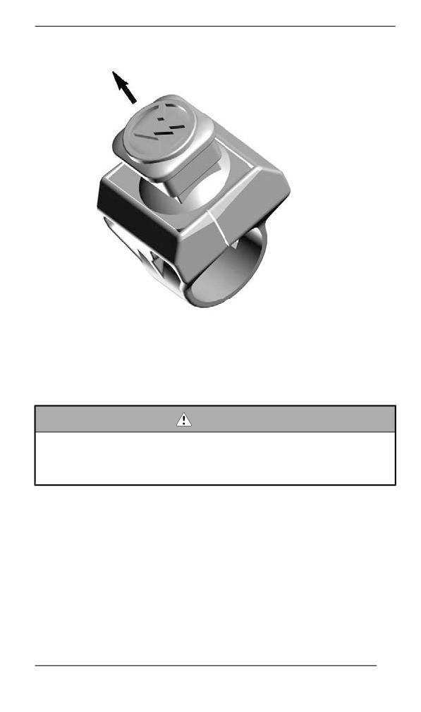
To allow engine starting, pull the switch up in ON position.
80
PRIMARY CONTROLS
ON POSITION
All operators of the snowmobile should familiarize themselves with the
function of the emergency engine stop switch by using it several times
on first outing and whenever stopping the engine thereafter. This en-
gine stopping procedure will become a reflex and will prepare opera-
tors for emergency situations requiring its use.
WARNING
If the switch has been used in an emergency caused by a sus-
pected malfunction, the source of the malfunction should be de-
termined and corrected before restarting engine. Visit an
authorized BRP snowmobile dealer for servicing.
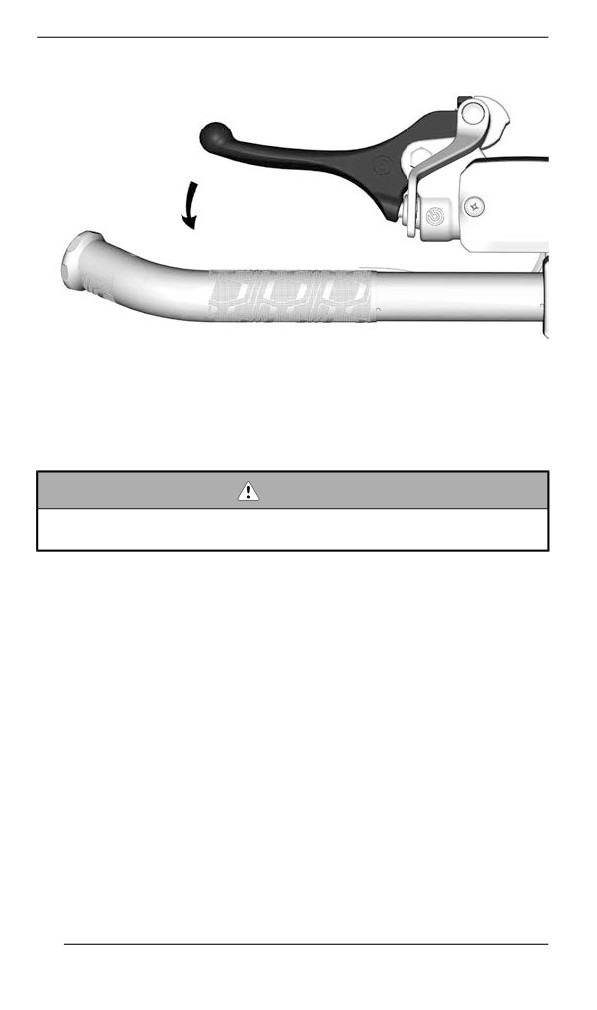
Brake Lever
Brake lever is located on the LH side of handlebar.
When squeezed, brake is applied. When released, it automatically re-
turns to the rest. Braking effect is proportional to the pressure applied
on the lever and to the type of terrain and its snow coverage.
81
PRIMARY CONTROLS
TYPICAL
Brake Lever Adjustment
WARNING
It is important to adjust the brake lever to the user size and nor-
mal riding position.
Proper brake lever position should allow:
- Good support for the index and middle finger on the lever.
- Use the outer end of the lever to optimize the force.
- Proper wrist alignment.
Taking the time to adjust and try out the brake lever before your first
snowmobile outing improves user comfort.
82
PRIMARY CONTROLS
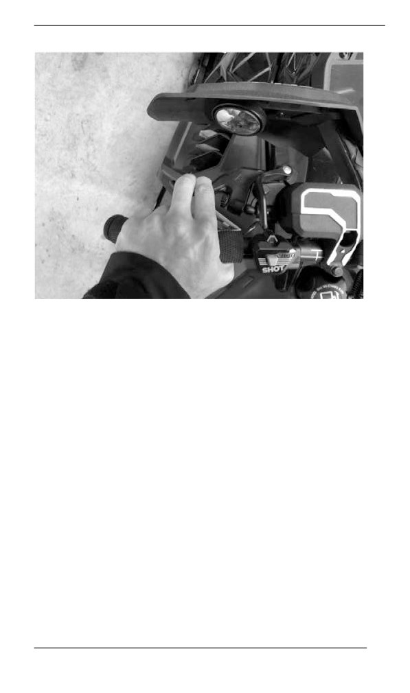
Adjusting the Brake Lever
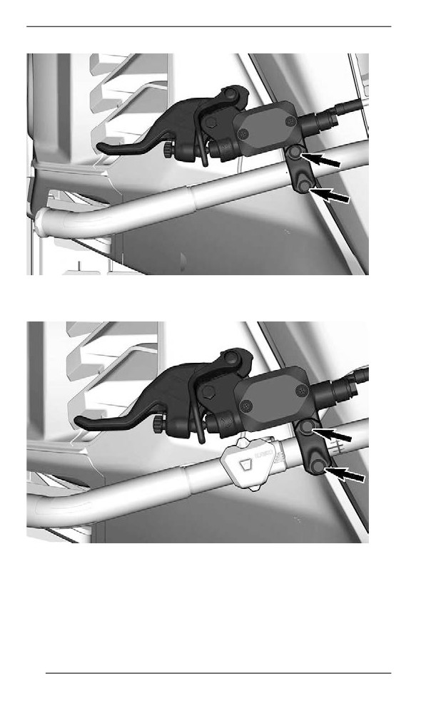
1. Loosen the two bolts enough to easily move the brake lever on the
handlebar.
NOTE:
If the two bolts are not loosen enough the brake lever can leave marks
on the handlebar.
Models with steel handlebar
83
PRIMARY CONTROLS
Models with aluminum handlebar and without multifunction
switch
Models with aluminum handlebar and with multifunction
switch
84
PRIMARY CONTROLS
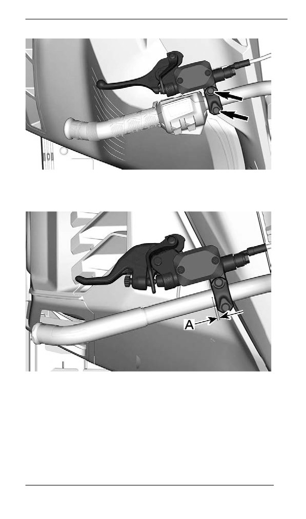
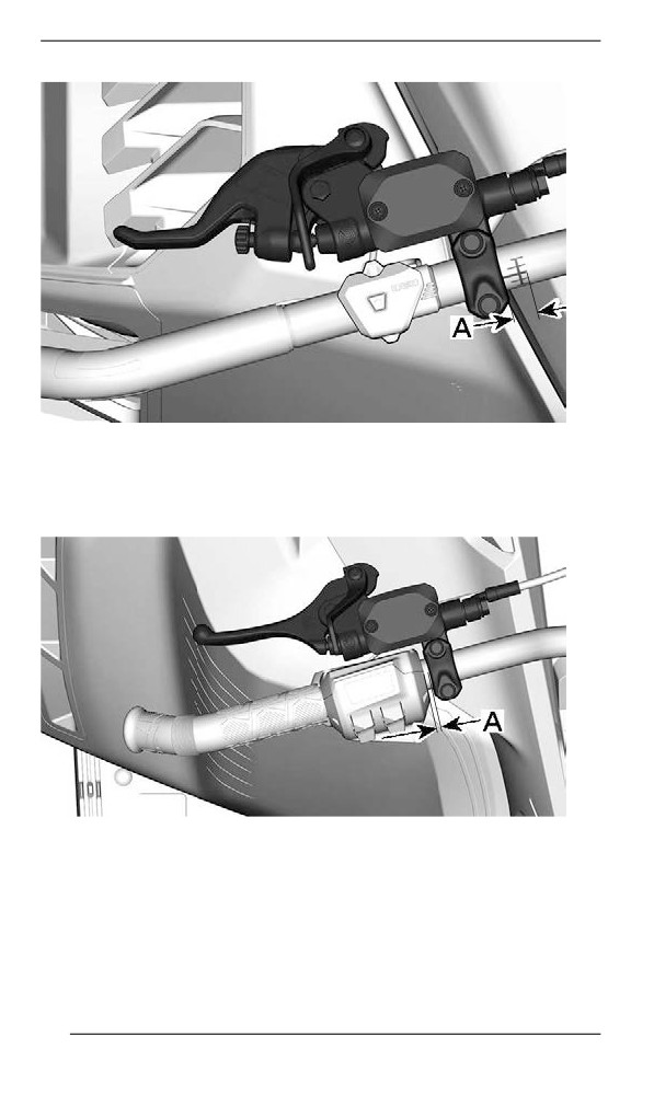
2. Locate the reference mark on the handlebar and respect the dis-
tance and rotation limits.
Models with steel handlebar
A. 0 to 5 mm (0 to 0.197 in) between the handlebar point and side of
the brake lever
Models with aluminum handlebar and without multifunction
switch
85
PRIMARY CONTROLS
A. 0 to 9 mm (0 to 0.354 in) between the start of the handlebar mark
and side of the brake lever
Models with aluminum handlebar and with multifunction
switch
A. 0 to 15 mm (0 to 0.590 in) between the side of the multifunction
switch and the side of the brake lever
3. With the operator on the driver seat, put the brake lever in the de-
sired position.
4. Tighten the two bolts to specification.
86
PRIMARY CONTROLS
TIGHTENING TORQUE
Brake lever adjustment
8.5 ± 1.5 Nm (75 ± 13 lbf-in)
bolts
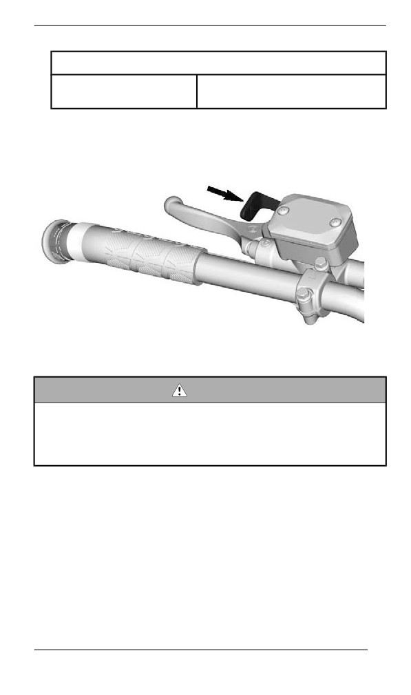
Parking Brake Lever
Parking brake lever is located on the LH side of handlebar.
TYPICAL
Parking brake should be used whenever snowmobile is parked.
WARNING
Make sure parking brake is fully disengaged before operating
the snowmobile. When you ride the vehicle, brake pads that are
caused to drag by a continuous pressure on the lever may
cause damage to the brake system and cause loss of braking
capacity and/or fire.
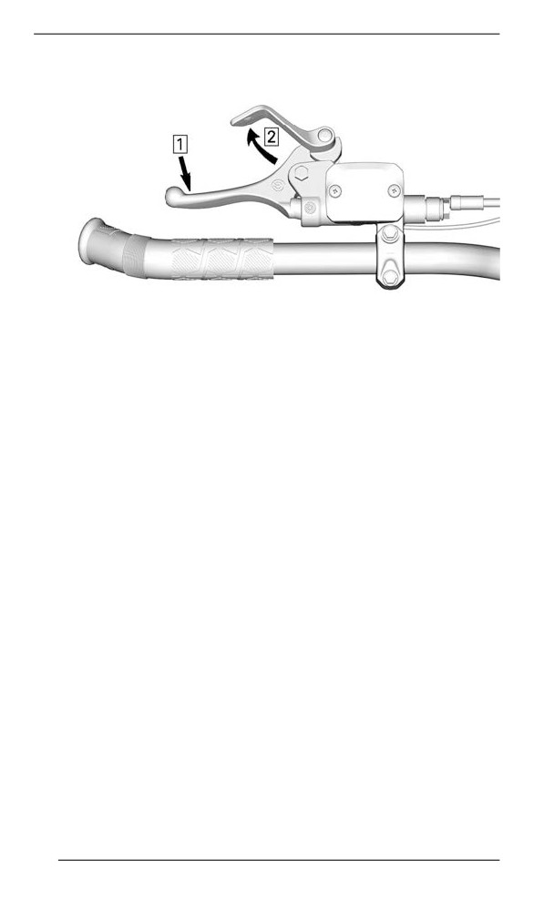
To Engage Parking Brake
Apply and hold brake, then lock brake lever using the parking brake
lever as shown.
87
PRIMARY CONTROLS
TYPICAL — ENGAGE MECHANISM
1. Apply and hold brake
2. Lock brake lever using parking brake lever
To Release Parking Brake
Squeeze brake lever. Parking brake lever will automatically return to
its original position. Always release parking brake before riding.
88
PRIMARY CONTROLS
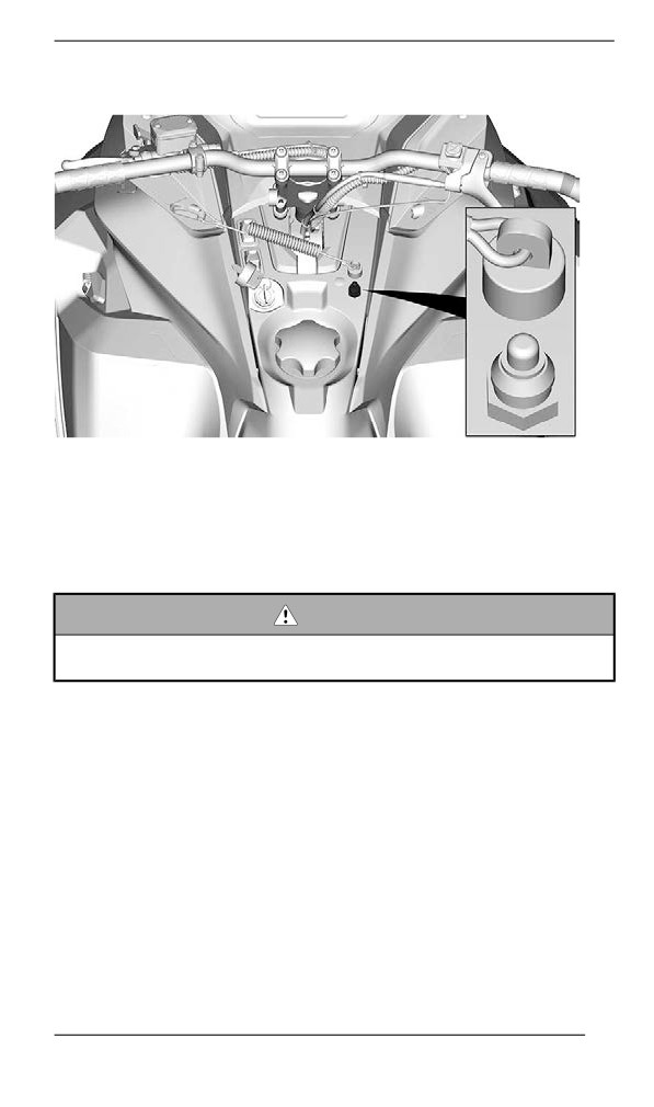
Engine Cut-off Swiitch
MECHANICAL SWITCH — TYPICAL
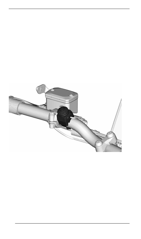
The engine cut-off switch (tether cord) is located on the console.
The tether cord cap must be securely snapped on the engine cut-off
switch to allow vehicle operation.
Pulling the tether cord cap from the switch shuts the engine off.
WARNING
Always attach the tether cord eyelet to clothing before starting
the engine.
89
SECONDARY CONTROLS
Some features may not apply to your model or could be optional.
Vehicle safety labels are not shown on illustrations. For information on
vehicle safety labels, refer to Vehicle Safety Labels.
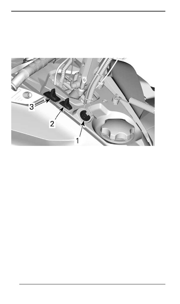
Console Swiitches (iif equiipped)
TYPICAL
1. Start/Electronic reverse switch
2. Heated grips switch
3. Headlights dimmer switch
Start/ Electronic Reverse Switch
Models with 600 EFI Engines
90
SECONDARY CONTROLS
TYPICAL
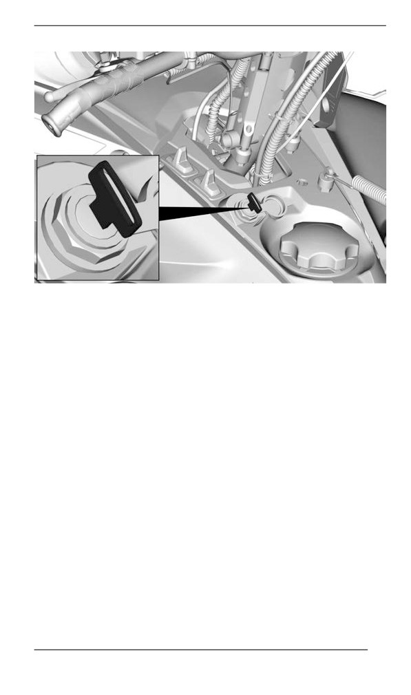
Turn the ignition key to start the engine. Refer to Engine Starting Pro-
cedure in basic procedures.
Once engine is started, turn the key to engage the electronic reverse.
Refer to Reverse (RER) in basic procedures.
Headlights Dimmer Button
Press to select HI or LOW beam. Lights are automatically ON when
the engine is running.
Heated Grips and Heated Throttle Lever Switch
NOTE:
Under 2000 RPM, heated grips will be limited at 50%.
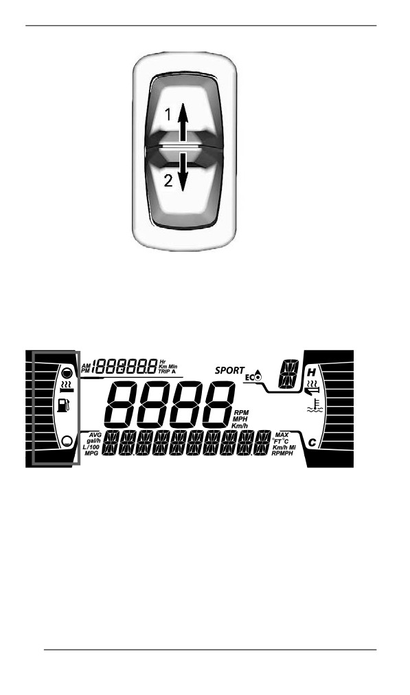
The switch on the console controls simultaneously the handlebar grips
and the throttle lever heat intensity.
The balance between the temperature of the throttle lever and the
grips can be adjusted.
Depress switch as required to select heating intensity to keep your
hands at a comfortable temperature.
91
SECONDARY CONTROLS
SWITCH ON CONSOLE
1. Increase heat
2. Decrease heat
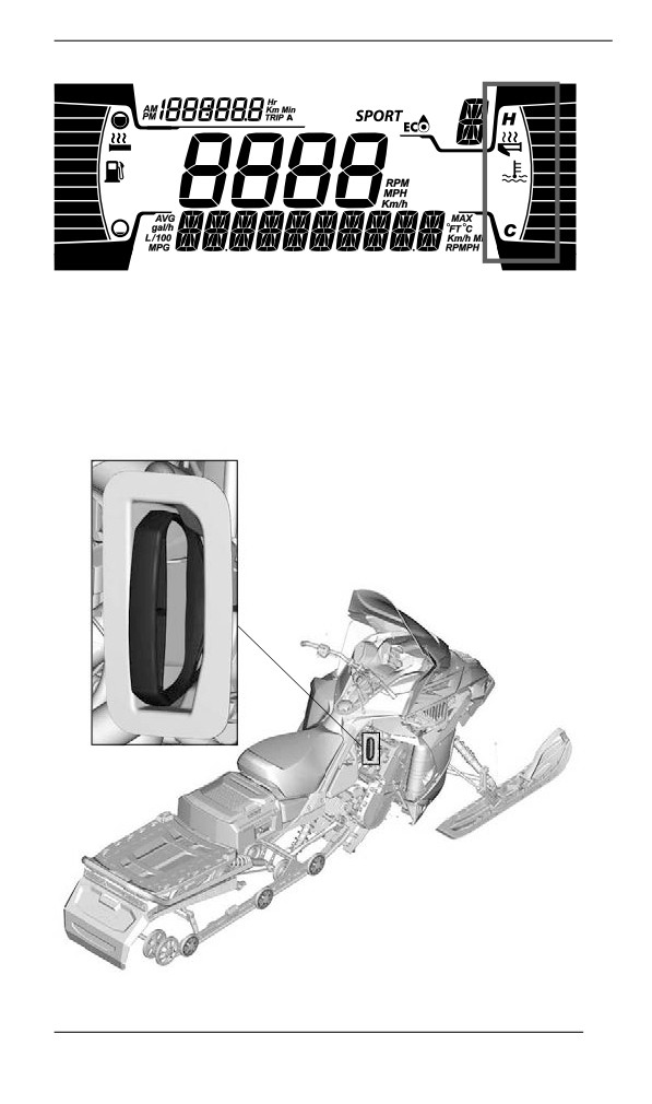
The heating intensity is displayed via the digital display.
HEATED GRIPS DISPLAY
92
SECONDARY CONTROLS
HEATED THROTTLE LEVER DISPLAY
Heated grips and throttle lever will be OFF when there are no bars dis-
played on the gauge.
When the switch is released, display will return to fuel level and engine
temperature.
Rewind Starter Handlle
93
SECONDARY CONTROLS
Auto-rewind type located on right hand side of snowmobile under the
side panel. Open right hand side panel to access the rewind starter
handle. Refer to Removing the Side Panels in this subsection. To en-
gage mechanism pull handle slowly until a resistance is felt then pull
vigorously. Slowly release handle.
NOTE:
The maximum torque that can be transmitted to the engine by the re-
wind starter is 80 Nm (59 lbf-ft). The maximum force that can be ex-
erted on the on the rope is 2 200 N (494.6 lbf).
Horn Button (if equiipped)
For vehicles sold in Finland
Press on the horn button to activate the horn.
TYPICAL
94
BODY AND SEAT
Wiindshielld
Removing the Windshield
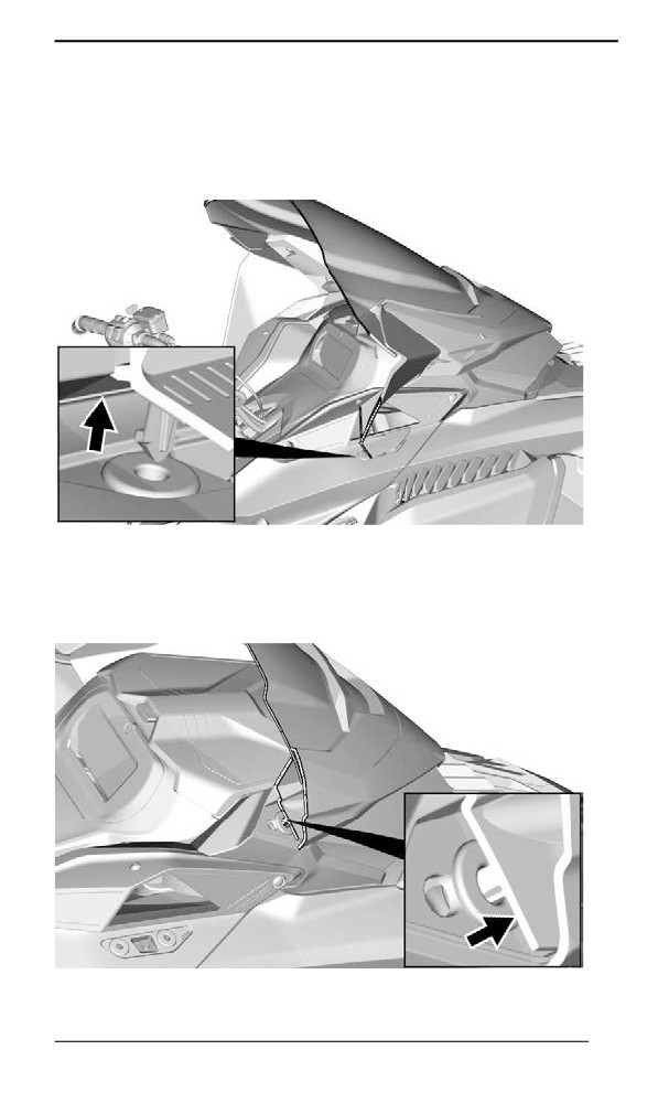
1. Pull off the deflector pins off the grommets, if applicable.
TYPICAL — WITH SIDE DEFLECTORS
2. Place hands on each sides of the windshield.
3. Pull the windshield up until both side pins come out of their rubber
grommets.
TYPICAL
95
BODY AND SEAT
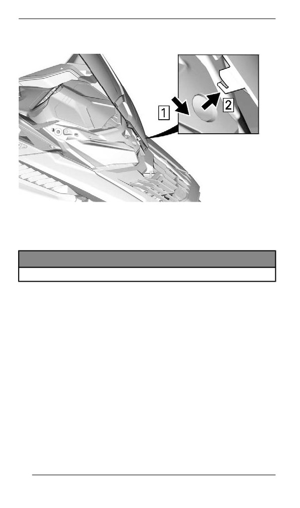
4. Disengage the center pin or tab, if applicable.
TYPICAL — CENTER TAB - WITH SIDE DEFLECTORS
Installing the Windshield
1. Lubricate the grommets using soapsuds, if required.
NOTICE
Do not lubricate grommets with any type of grease.
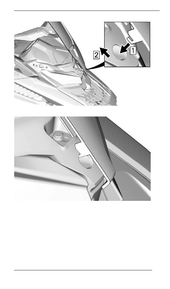
2. Insert center pin or tab in headlamp module hole.
96
BODY AND SEAT
TYPICAL - CENTER TAB - WITH SIDE DEFLECTORS
TYPICAL
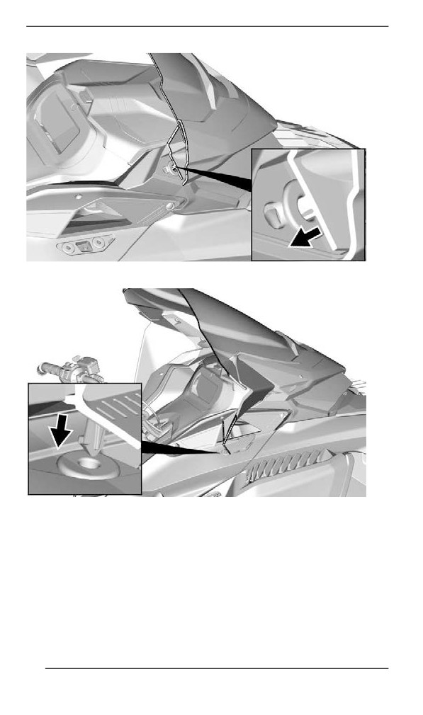
3. Secure windshield by inserting the windshield pins into the
grommets.
97
BODY AND SEAT
TYPICAL
TYPICAL — WITH SIDE DEFLECTORS
Front Storage Compartment
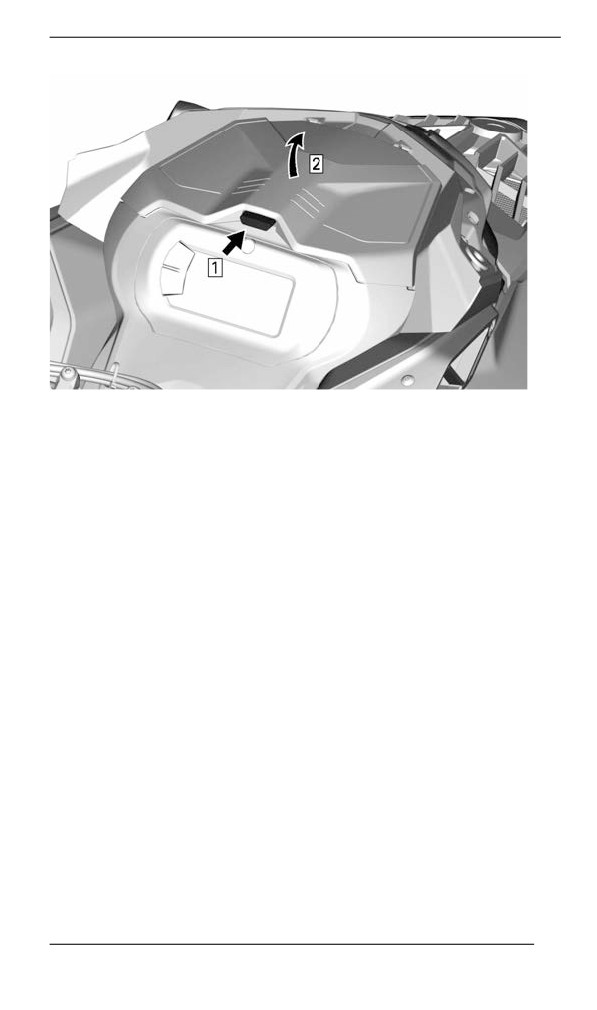
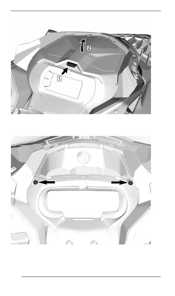
A storage compartment is located at the front of the vehicle, above the
gauge.
The Operator's Guide and the emergency starter rope are in the front
storage compartment.
To open, push the button and lift the cover.
98
BODY AND SEAT
TYPICAL
NOTE:
When closing, make sure cover is secured properly. You will hear a
"click".
Hood
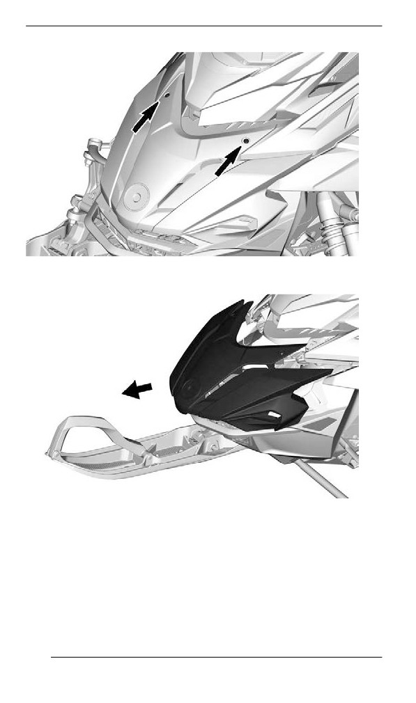
Removing the Hood
1. Remove hood screws.
99
BODY AND SEAT
TYPICAL
2. Pull the hood forward.
TYPICAL
Installing the Hood
1. The installation is the reverse of removal procedure. However, pay
attention to the following.
100
BODY AND SEAT
TIGHTENING TORQUE
Hood Torx screw
2.5 ± 0.2 Nm
Siide Panels
WARNING
Never operate engine with side panels opened or removed from
vehicle.
Removing the Side Panels
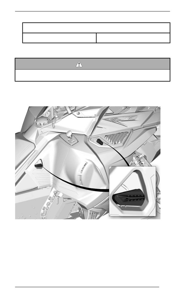
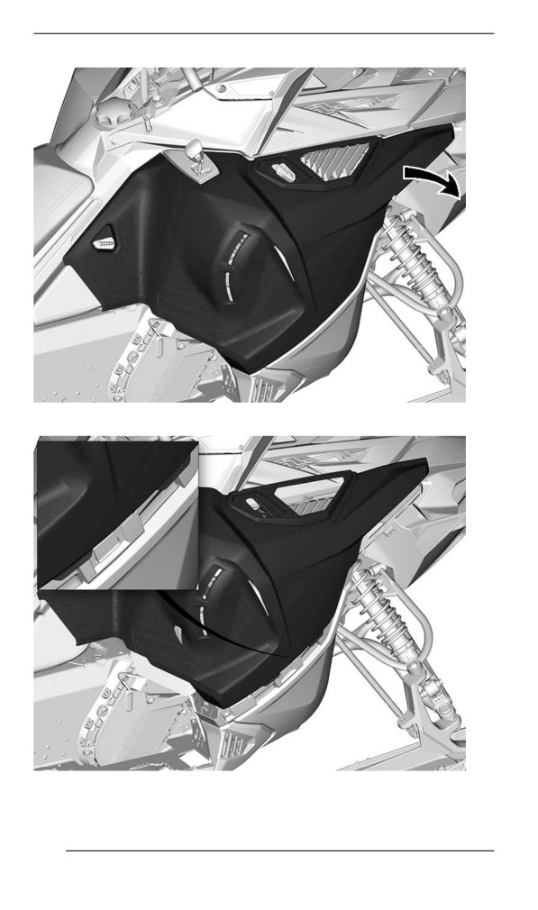
1. Unlock all latches, then open panel.
TYPICAL
2. Pivot side panel around lower edge.
101
BODY AND SEAT
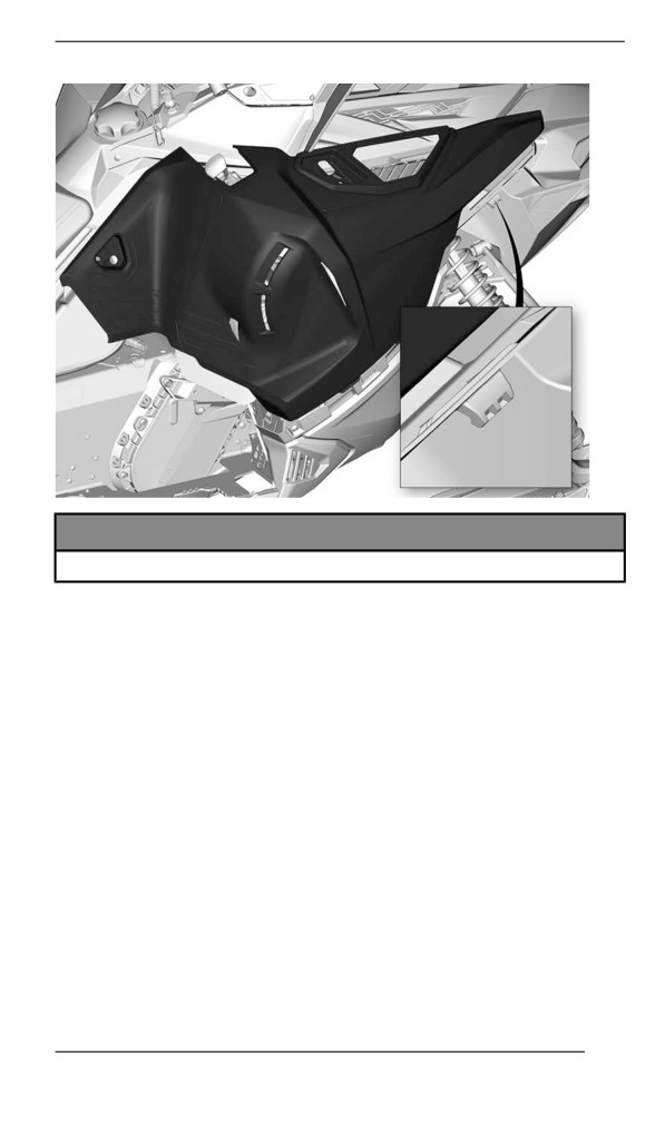
3. Disengage panel tabs.
4. Free panel from side hull tab.
102
BODY AND SEAT
NOTICE
Make sure to place panel in a safe place to avoid scratching.
Installing the Side Panels
The installation is the reverse of the removal procedure.
Upper Body Modulle
Removing the Upper Body Module
1. Remove:
- Windshield
- Hood
- Side panels
2. Open the storage compartment.
103
BODY AND SEAT
TYPICAL
3. Remove the gauge support retaining screws.
TYPICAL
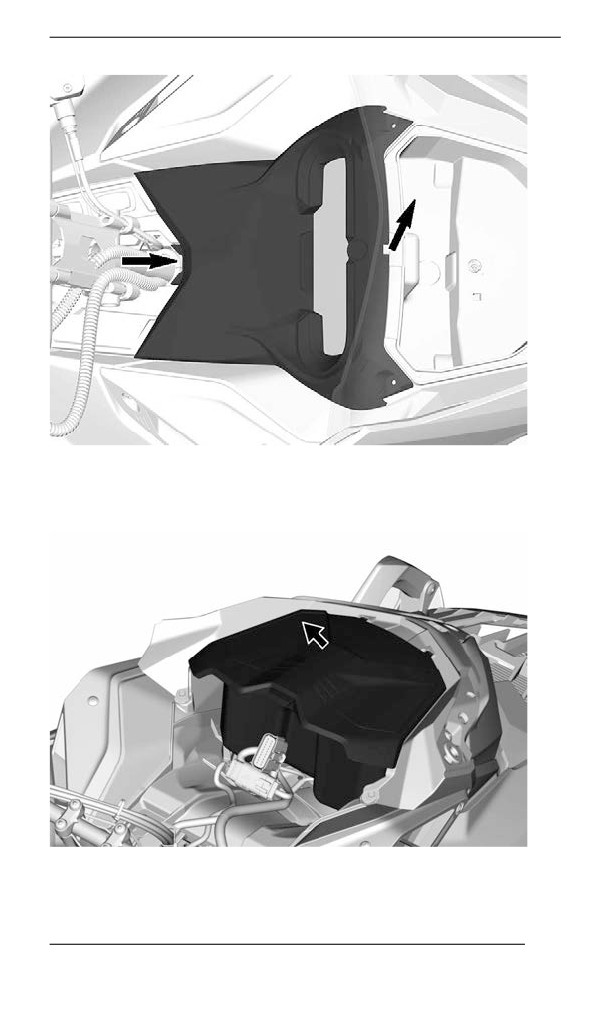
4. Lift the front of the gauge support, then slide it forward to remove it.
104
BODY AND SEAT
5. Disconnect gauge connector and remove support .
6. Lift storage compartment and disconnect 12V power outlet connec-
tors before removing the storage compartment (if equipped).
TYPICAL
105
BODY AND SEAT
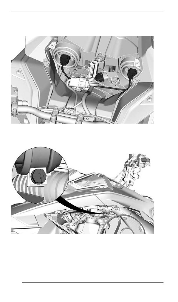
7. Disconnect the headlight and MAPTS
(2-stroke engine)
connectors.
TYPICAL
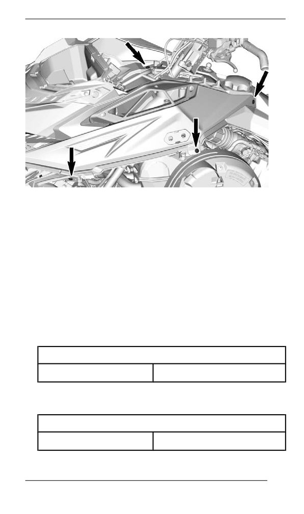
8. Loosen the air intake duct clamp.
9. Remove the upper body module retaining screws on both sides.
106
BODY AND SEAT
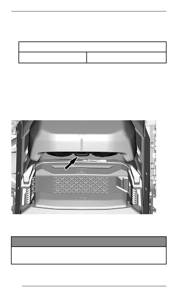
10. Remove the upper body module.
1. Grab the upper body module in the gauge support section.
2. Pull the module forward.
3. Remove the module from the vehicle.
Installing the Upper Body Module
The installation is the reverse of the removal procedure. However, pay
attention to the following.
1. Lower the upper body module in place.
NOTE:
Make sure the air intake duct is positioned correctly in the boot.
2. Tighten air intake duct clamp.
TIGHTENING TORQUE
Duct clamp
1 ± 0.2 Nm
3. On both sides, install the upper body module retaining screws.
4. Connect the IR light connector.
5. Install the hood.
TIGHTENING TORQUE
Upper body screws
2.5 ± 0.2 Nm
107
BODY AND SEAT
6. Connect the headlight connectors.
7. Install the storage compartment but leave the cover open.
8. Install gauge, secure with the screws.
TIGHTENING TORQUE
Gauge screws
2.5 ± 0.2 Nm
9. Install:
- Side panels
- Hood
- Windshield
Seat
Removing the Seat
Release the latch at the back of the seat.
Slide seat rearwards to remove it.
Installing the Seat
NOTICE
Riding the vehicle with any objects between the seat and the
fuel tank could damage the fuel tank. NEVER place any objects
between seat and fuel tank.
108
BODY AND SEAT
Place seat over the hooks, then slide it forward.
Securely engage the latch.
WARNING
Make sure seat is securely latched before riding.
109
EQUIPMENT
Some features may not apply to your model or could be optional.
Operator''s Guiide
The Operator's Guide should be stored in the Front Storage
Compartment.
Drive Belt Guard
Removing the Drive Belt Guard
WARNING
NEVER operate engine:
– Without shields and belt guard securely installed.
– With hood and/or side panels opened or removed.
NEVER attempt to make adjustments to moving parts while en-
gine is running.
NOTE:
Belt guard is purposely made slightly oversize to maintain tension on
its pins and retainers preventing undue noise and vibration. It is impor-
tant that this tension be maintained when reinstalling.
Remove tether cord cap from engine cut-off switch.
Open the LH side panel. See procedure in this section.
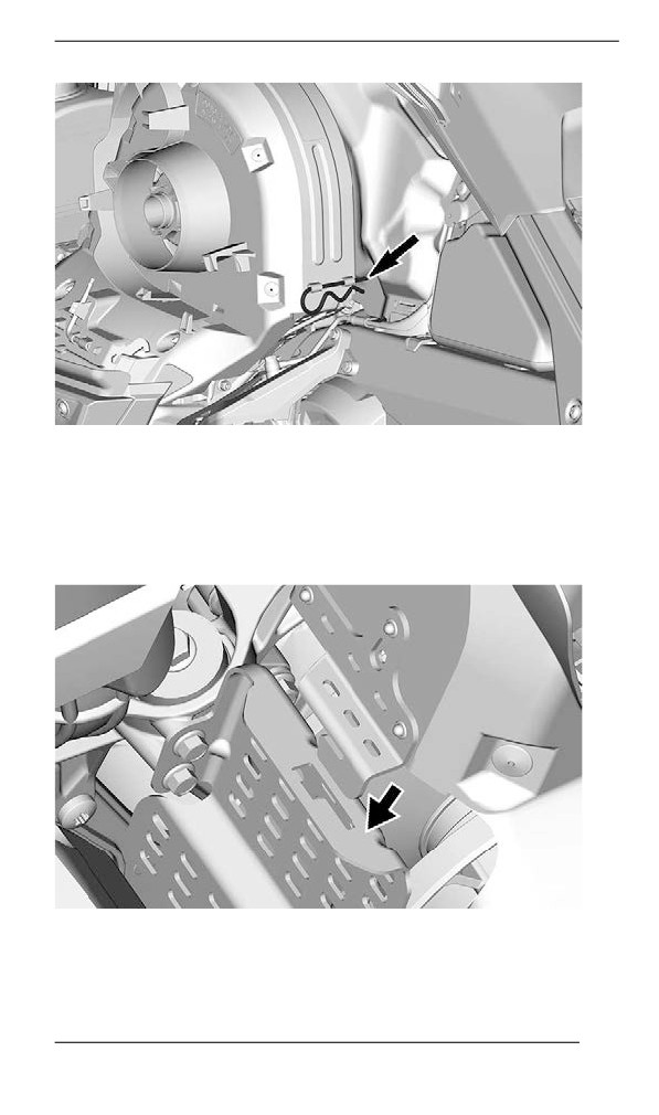
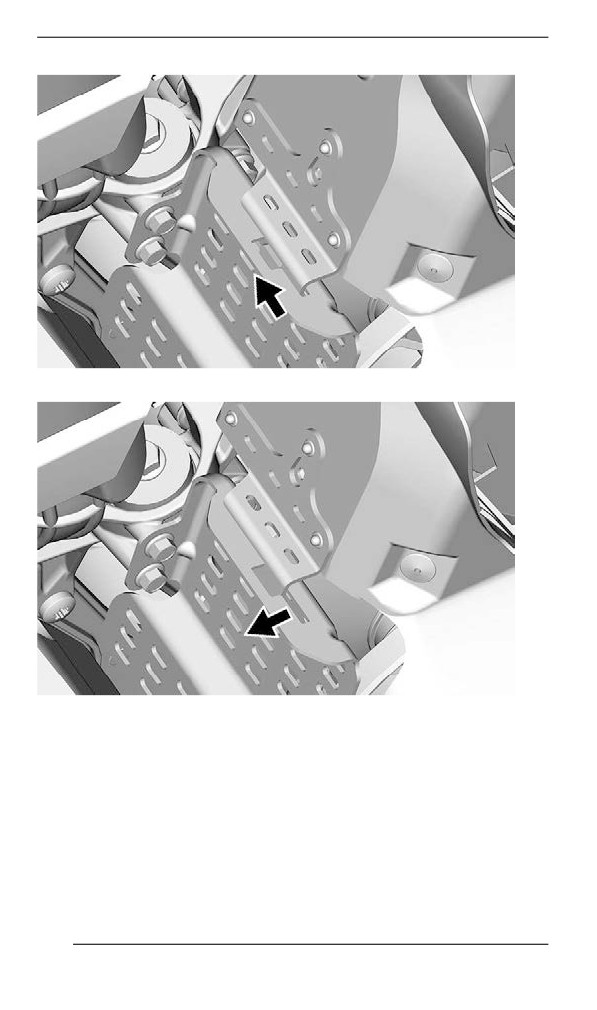
Remove retaining pin.
110
EQUIPMENT
TYPICAL
Lift rear portion of guard then release from front tab.
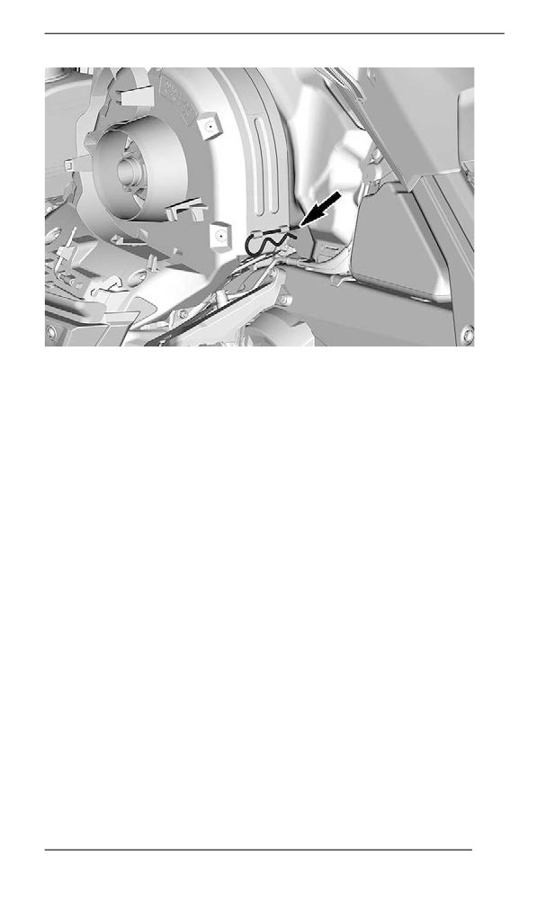
Installing the Drive Belt Guard
Insert belt guard tab in front support slot.
Push drive belt guard toward engine then toward front of vehicle.
111
EQUIPMENT
Position the rear portion of the belt guard over the retainer and secure
it using the retaining pin.
112
EQUIPMENT
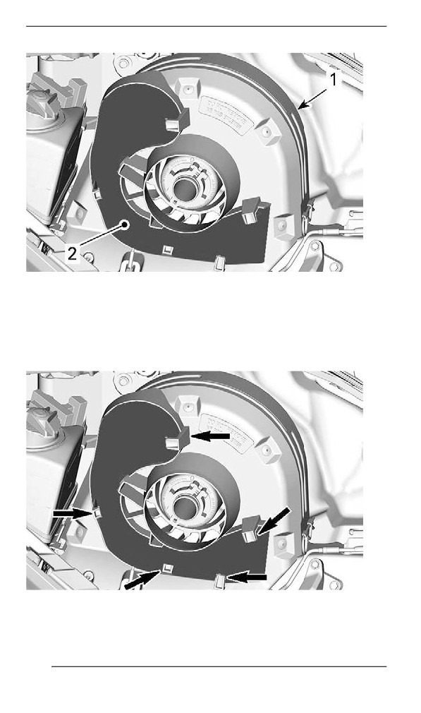
Spare Driive Bellt Hollder
A spare drive belt can be stored in a holder located on the drive belt
guard.
NOTE:
The spare drive belt is not supplied with the snowmobile.
Position spare drive belt into drive belt guard slot.
113
EQUIPMENT
TYPICAL
1. Drive belt guard
2. Slot
Secure in place by sliding it behind the tabs.
TYPICAL
114
EQUIPMENT
Tools
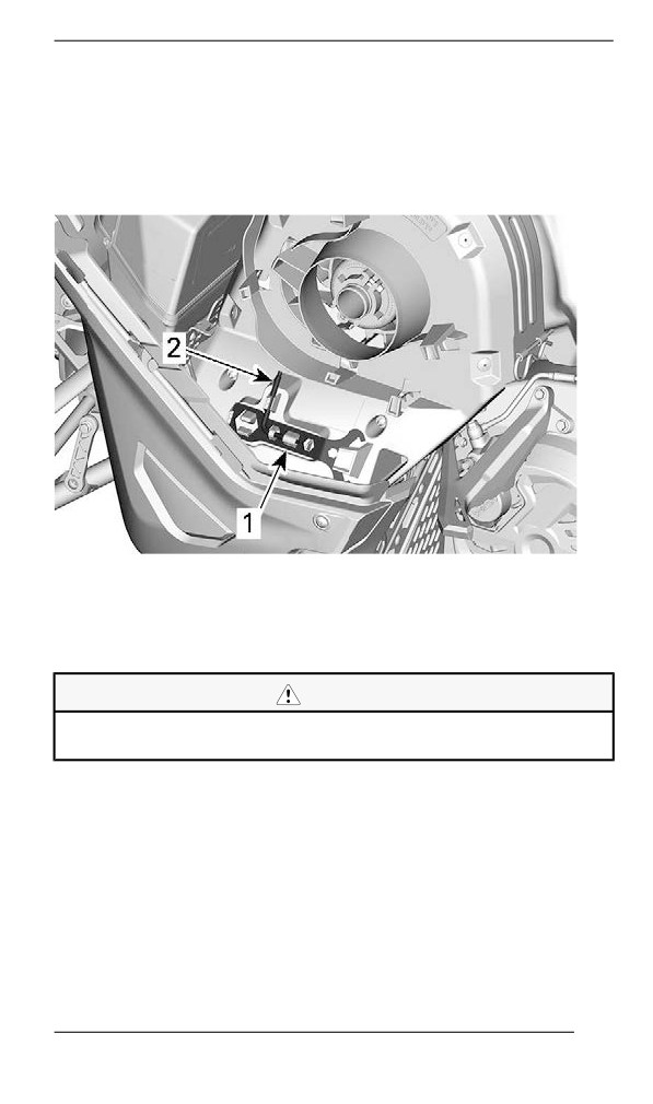
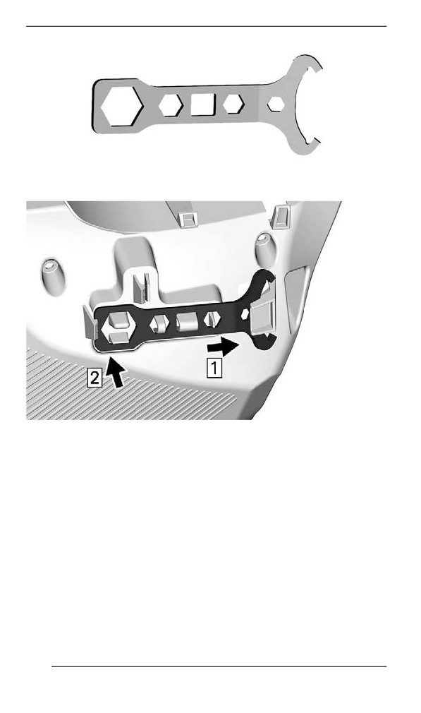
A part of the drive belt guard is designed to hold the tools allowing for
basic maintenance.
The tools are supplied with the vehicle. They should always be in-
stalled in their proper location and orientation.
TYPICAL - DRIVE BELT GUARD TOOLS LOCATION
1. Suspension adjustment tool
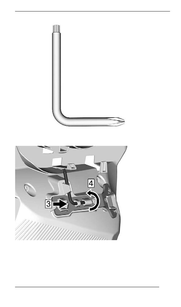
2. Pulley expander and headlight adjustment tool
Install in the following sequence:
CAUTION
Make sure tools are secured properly. Tools may detach and
cause damage to rotating parts.
1. Slide the suspension adjustment tool open end under retaining tab.
115
EQUIPMENT
SUSPENSION ADJUSTMENT TOOL
2. Press the closed end on the retaining tabs.
3. Slide the Pulley expander and headlight adjustment tool short end
into hole.
116
EQUIPMENT
PULLEY EXPANDER AND HEADLIGHT ADJUSTMENT TOOL
4. Rotate and clip long end in place.
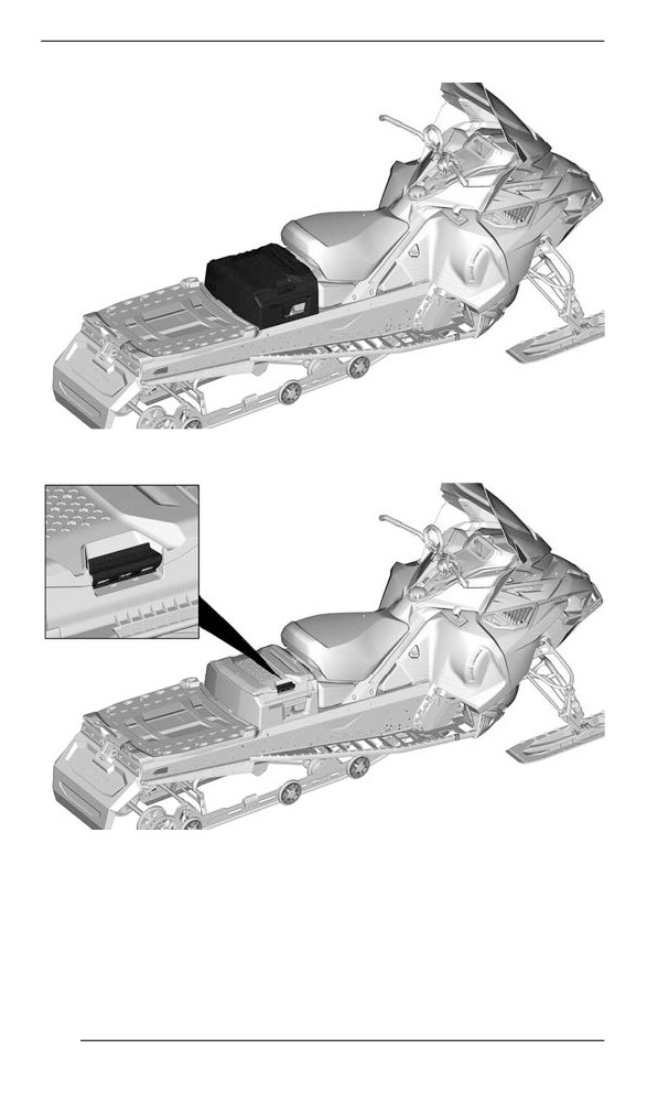
Rear Storage Compartment
A storage compartment is located at the rear of the seat.
117
EQUIPMENT
To open, pull on the handle .
118
COMPACT DIGITAL DISPLAY
WARNING
Reading the digital display can distract from the operation of
the vehicle, particularly from constantly scanning the
environment.
NOTE:
The digital display is factory preset in Imperial units and in English. To
change units or language, contact an authorized BRP snowmobile
dealer.
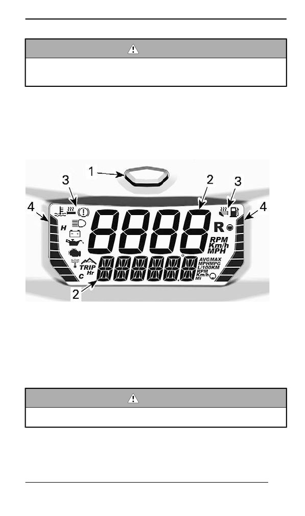
Diispllay Features
COMPACT DIGITAL DISPLAY
1. Mode button
2. Digits
3. Icons
4. Bar gauges
The digital display also has a built-in beeper.
Digital Display
WARNING
Never adjust or set functions on the digital display while riding
the vehicle.
To set the displays to your preference, refer to Display Combination
Selection.
119
COMPACT DIGITAL DISPLAY
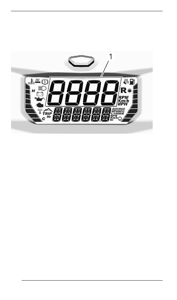
Upper Display
The upper display is used to display:
- Vehicle speed.
- Engine speed (RPM).
1. Upper Display
Lower Display
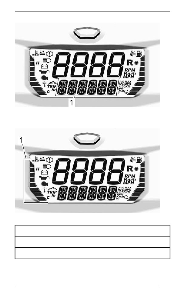
The lower display is used to display
- Various information (in combination with the upper display)
- Messages, refer to Icons and Messages and Monitoring System
for details.
- Fault codes, refer to Monitoring System for details.
120
COMPACT DIGITAL DISPLAY
1. Lower display
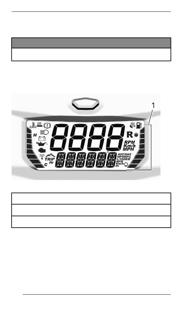
LH side Bar Gauge
1. LH bar gauge
LH Bar Gauge Information
Engine coolant temperature
Heated grips level
121
COMPACT DIGITAL DISPLAY
The LH side bar gauge displays the engine coolant temperature ex-
cept while adjusting the heating elements.
NOTICE
If engine overheats, stop vehicle in a safe place. Refer to
TROUBLESHOOTING.
For details on heated grips operation, refer to Heated Grips and Throt-
tle Lever Switch in Secondary Controls.
RH Side Bar Gauge
1. RH bar gauge
RH Bar Gauge Information
Fuel level
Heated throttle lever level
The RH side bar gauge displays the fuel level except while adjusting
the heated throttle lever.
For details on heated throttle lever operation, refer to Heated Grips
and Throttle Lever Switch in Secondary Controls.
122
COMPACT DIGITAL DISPLAY
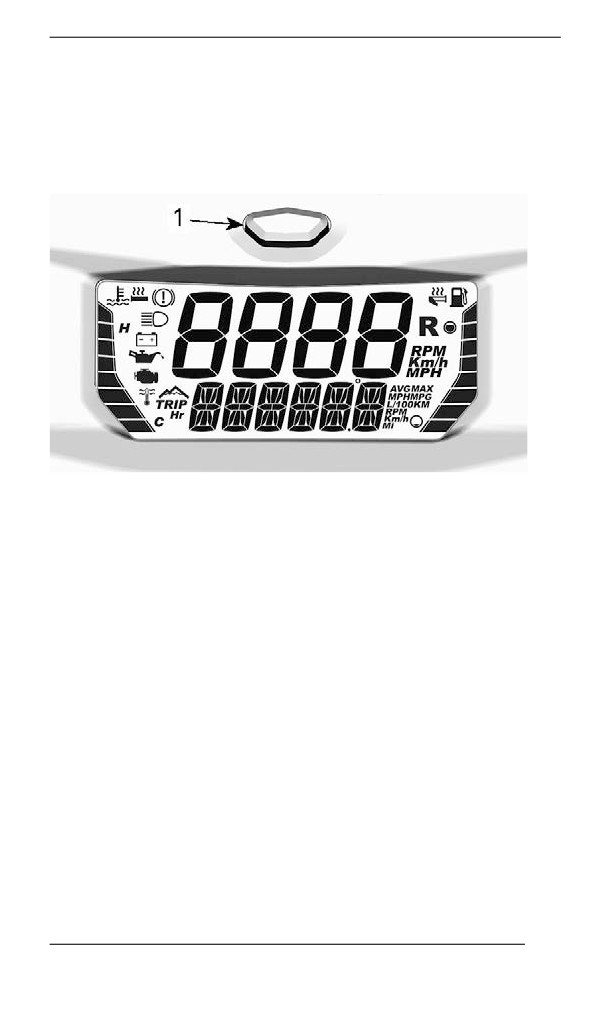
Display Combination Selection
The upper and lower displays can be set as combination only. They
cannot be set separately.
To scroll through the information options, press and release the mode
button repeatedly until the desired information is displayed.
1. Gauge mode button
123
COMPACT DIGITAL DISPLAY
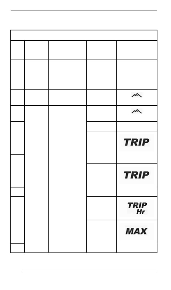
refer to the following table for available combinations.
Available Display Combinations
Icon/
Icon/
Upper
Lower
Specific
Specific
Display
Display
information
information
Vehicle
Vehicle
speed
Km/h or MPH
speed
Km/h or MPH
1
OR
OR
OR
OR
Engine
RPM
Engine
RPM
RPM
speed
Engine
RPM
Altitude
RPM
M or F
2
Altitude
M or F
Odometer
Km or MI
3
Trip
odometer
A(1)
Km or MI
4
Vehicle
Trip
Km/h or MPH
odometer
speed
B (1) (2)
5
Km or MI
Trip hour
(1)
6
Top speed
(1)
7
Km/h or MPH
124

COMPACT DIGITAL DISPLAY
Average
speed (1)
8
Km/h or MPH
Top RPM
9
(1)
RPM
10
Vehicle
Average
Km/h or MPH
speed
fuel
consump
tion
L/100Km or
11
MPG
Engine
coolant
E
12
tempera
and C or F
ture
(1) Press and hold the mode button to reset
(2) Resetting the trip odometer B also resets the average fuel
consumption
NOTE:
Make sure to display the vehicle speed whenever this information is
necessary.
125
COMPACT DIGITAL DISPLAY
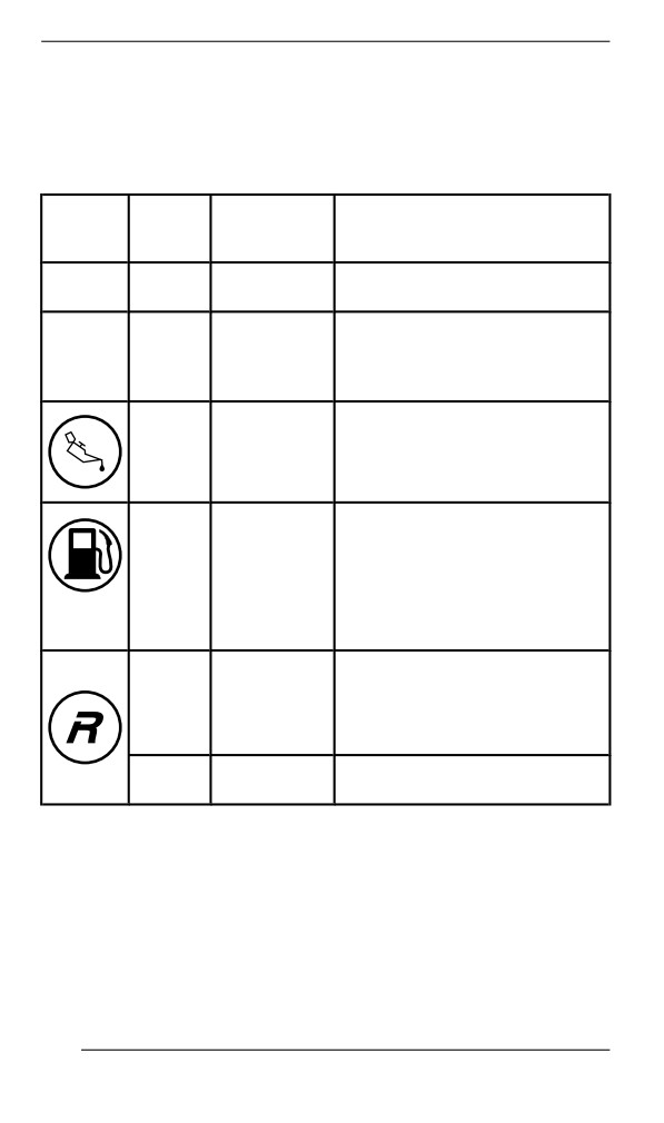
Icons and Messages
See table below for usual icons and messages.
For details on malfunction pilot lamps and messages, refer to Monitor-
ing System.
Message
Icon
Beeper
Lower
Description
Display
2 short
At power up, with a good key.
—
GOOD KEY
beeps
Vehicle ready for use.
Displayed during break-in
—
—
BREAK-IN
period. Refer to Break-in Period
4 short
beeps
Injection oil level is low. Stop
every
LOW OIL
vehicle in a safe place then,
5
replenish injection oil reservoir.
minutes
Low fuel level. No bar left in fuel
—
—
level display. Replenish fuel
tank as soon as possible.
(blink
ing)
Long
beeps
repeat
REVERSE
Reverse is selected.
ing
slowly
3 short
Reverse did not engage, try
REV. FAIL
beeps
again.
126

COMPACT DIGITAL DISPLAY
Message
Icon
Beeper
Lower
Description
Display
High beam headlights are
—
—
selected.
Engine and/or injection oil need
to warm-up before normal
operation. The engine's RPM is
limited until desired temperature
—
—
WARM UP
is reached
(up to
10 minutes
when driving). Warm-up period
may occur after a restart in very
cold weather.
127
FUEL
Fuel Requirements
NOTICE
Always use fresh gasoline. Gasoline will oxidize; the result is
loss of octane, volatile compounds, and the production of gum
and varnish deposits which can damage the fuel system.
Alcohol fuel blending varies by country and region. Your vehicle has
been designed to operate using the recommended fuels, however, be
aware of the following:
- Use of fuel containing alcohol above the percentage specified by
government regulations is not recommended and can result in the
following problems in the fuel system components:
- Starting and operating difficulties.
- Deterioration of rubber or plastic parts.
- Corrosion of metal parts.
- Damage to internal engine parts.
- Inspect frequently for the presence of fuel leaks or other fuel sys-
tem abnormalities if you suspect the presence of alcohol in gaso-
line exceeds the current government regulations.
- Alcohol blended fuels attract and hold moisture which may lead to
fuel phase separation and can result in engine performance prob-
lems or engine damage.
Recommended Fuel
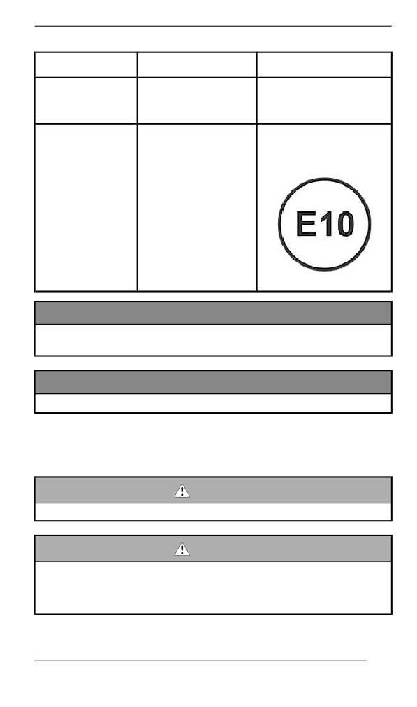
Use unleaded gasoline containing MAXIMUM 10% ethanol. The gaso-
line must have the following minimum octane requirements.
128
FUEL
Fuel type
Engine
Min. octane rating
87 Pump Posted AKI
Fuel with NO
600 EFI
(RON+MON)/2)
ethanol
92 RON
91 AKI (RON+MON)/2
95 RON
Fuel which may
contain up to
600 EFI
10% MAX
ethanol
NOTICE
Never experiment with other fuels. Engine or fuel system dam-
ages may occur with the use of an inadequate fuel.
NOTICE
Do NOT use fuel from fuel pumps labeled E85.
Use of fuel labeled E15 is prohibited by U.S. EPA Regulations.
Fueliing Procedure
WARNING
Always stop engine before refueling.
WARNING
Fuel is flammable and explosive under certain conditions.
Never use an open flame to check fuel level.
Never smoke or allow flame or spark in vicinity.
Always work in a well-ventilated area.
129
FUEL
NOTE:
Do not sit or lean on seat when fuel tank cap is not properly installed.
1. Stop engine.
2. Have operator and passenger get off vehicle.
WARNING
Do not allow anyone seated on the vehicle while fueling.
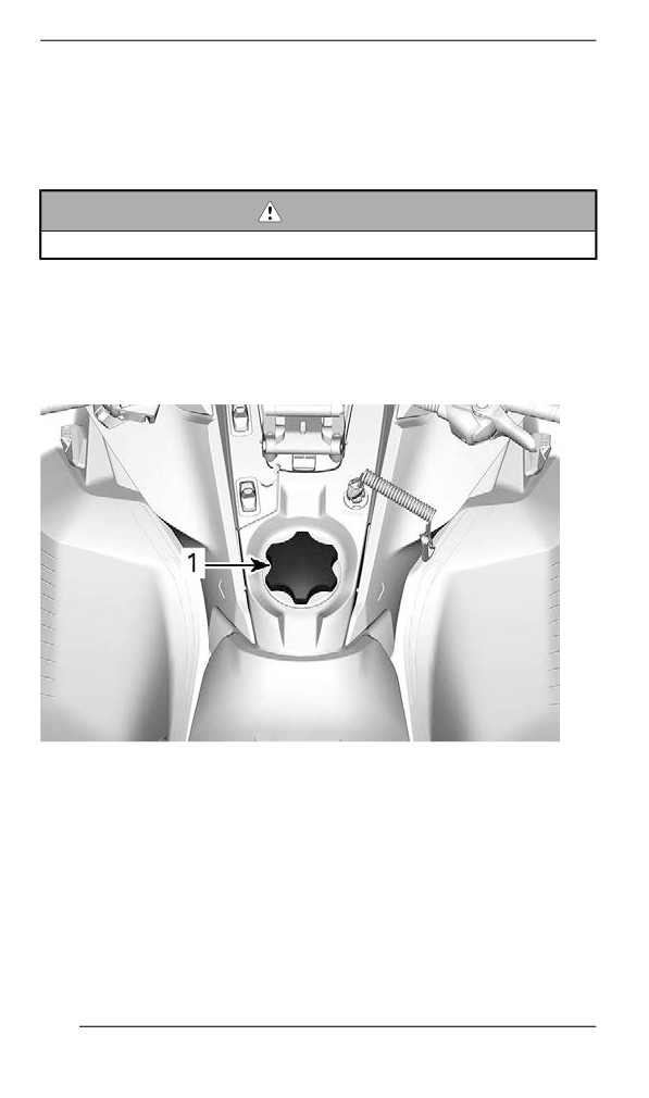
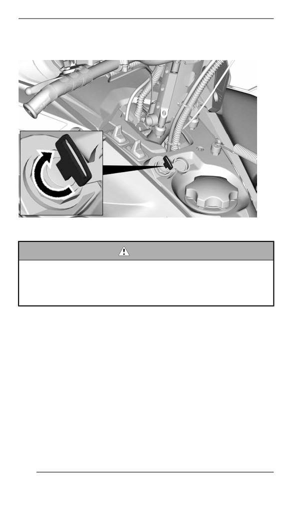
3. Unscrew slowly the fuel reservoir cap counterclockwise to stabilize
pressure before removing it.
NOTE:
A short whistling sound is normal.
TYPICAL
1. Fuel tank cap
4. Insert the spout into the filler neck.
5. Pour fuel slowly so that air can escape from the tank and prevent
fuel flow back. Be careful not to spill fuel.
6. Stop filling when the fuel reaches the bottom of filler neck. Do not
overfill.
130
FUEL
WARNING
Never top up the fuel tank before placing the vehicle in a warm
area. As temperature increases, fuel expands and may
overflow.
7. Fully tighten fuel reservoir cap clockwise.
WARNING
Always wipe off any small fuel spillage from the vehicle. If a ma-
jor spillage occurs, remove side panels to remove fuel vapors
from engine compartment before starting.
NOTE:
Do not sit or lean on seat when fuel tank cap is not properly installed.
131
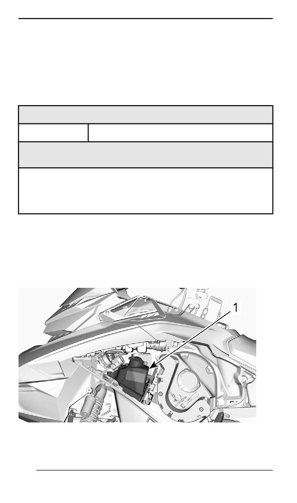
INJECTION OIL
Recommended Injection Oill
Rotax® engines were developed and validated using the XPS® oil.
BRP recommends the use of its XPS injection oil or an equivalent at
all time. Damages caused by the use of an injection oil not suitable for
this 2-stroke fuel injection engine may not be covered by the BRP Lim-
ited Warranty.
RECOMMENDED Injection Oil
600 EFI
XPS 2T Synthetic Blend Oil (semi-synthetic)
IF THE RECOMMENDED XPS ENGINE OIL IS NOT
AVAILABLE
Use a 2-stroke lubricant designed for snowmobiles meeting or
exceeding the following lubricant industry specifications:
- JASO FD (M345-2004)
- SAE Grade 4 (F / M 4)
Injectiion Oiil Level Veriifiicatiion
The injection oil reservoir is located behind the LH side panel. Refer to
Equipment for opening procedure.
Always maintain a sufficient amount of recommended injection oil in
the injection oil reservoir.
1. Oil reservoir
Marks on the tank indicates "3/8" and "1/2" of the total amount of oil.
132
INJECTION OIL
NOTICE
Check level and refill every time you refuel.
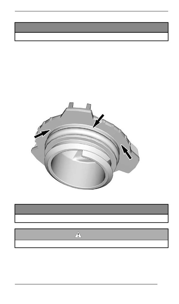
Adding Injection Oil
Remove injection oil reservoir cap.
Add injection oil.
NOTE:
Do not overfill.
Wipe the reservoir cap seal and flange area.
Reinstall cap.
NOTICE
Do not overtighten.
WARNING
Wipe off any oil spills. Oil is highly flammable when heated.
133
BREAK-IN PERIOD
Operatiion During Break-In
Engine
During the break-in period:
- Avoid prolonged full throttle operation.
- Avoid sustained accelerations.
- Avoid prolonged cruising speeds.
- Avoid engine overheating.
However, brief accelerations and speed variations contribute to a
good break-in.
During a predetermined period, the engine management system con-
trols some engine parameters.
The duration is based on fuel volume. It will take approximately two
fuel tanks to complete the break-in.
During this period:
- The engine performance and behavior will not be optimal.
- The fuel and oil consumption will be higher.
Drive Belt
A new drive belt requires a break in period of 50 km (30 mi).
During the break-in period:
- Avoid strong acceleration and deceleration.
- Avoid pulling a load.
- Avoid high speed cruising.
If the vehicle creeps, lower the drive belt height from the preliminary
setting. Refer to Drive Belt in maintenance procedure.
134
BASIC PROCEDURES
Engine Startiing Procedure
Procedure
1. Apply parking brake.
2. Recheck throttle control lever operation.
3. Put your helmet on.
4. Ensure that the tether cord cap is installed on the engine cut-off
switch and that the cord is attached to your clothing eyelet.
5. Ensure that the emergency engine stop switch is in the ON position
(up).
WARNING
Never depress throttle while starting engine.
6. Release parking brake.
NOTE:
For an initial cold start, do not release parking brake. Perform the ve-
hicle warm-up procedure as explained below.
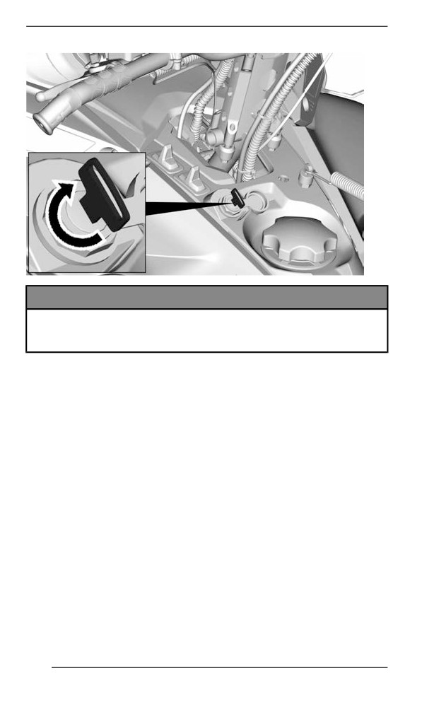
7. Turn the ignition key clockwise to engage the electric starter and
start the engine.
135
BASIC PROCEDURES
NOTICE
Do not engage electric starter for more than 10 seconds at a
time. A rest period should be observed between the cranking
cycles to allow electric starter to cool down.
Vehiiclle Warm-Up
Before every ride, vehicle has to be warmed up as follows.
1. Start engine as explained in Engine Starting Procedure above.
2. Allow engine to warm up one or two minutes at idle speed.
NOTE:
Engine will shut down after approximately 12 minutes of idling.
3. Disengage parking brake.
4. Apply throttle until drive pulley engages. Drive at low speed the first
two or three minutes.
136
BASIC PROCEDURES
NOTICE
If vehicle does not move when throttle is applied, stop engine,
remove tether cord cap from the engine cut-off switch, then do
the following.
– Check if skis are stuck on the ground. Lift one ski at a time
by the handle, then put it down.
– Check if track is stuck on the ground. Lift rear of snowmobile
enough to clear track from the ground, then drop.
– Check rear suspension for hard snow or ice accumulation
that could interfere with track rotation. Clean the area.
CAUTION
Beware of injuries by using proper lifting techniques, notably
using your legs force. Do not attempt to lift the rear of vehicle if
it is above your limits.
WARNING
Make sure tether cord cap is removed before standing in front
the vehicle, getting close to the track or rear suspension
components.
NOTE:
Warm-up is electronically controlled. During this period (up to 10 mi-
nutes depending on ambient temperature), engine RPM is limited.
Reverse (RER)
When the engine is running, turning the starting key will slow down the
engine RPM to almost a stop and advance the ignition timing to invert
the crankshaft rotation.
- The engine will automatically shift into forward when restarting
after stopping or stalling.
- Shifting procedure will take place only when the engine is running.
- If engine is running at a speed above 4300 RPM, the function of
the RER button is disabled.
- It is recommended to warm up the engine to its normal operating
temperature before shifting.
Shifting in Reverse
1. Bring vehicle to a complete stop.
2. Apply and hold brake. Remain seated, refer to Rider Position (Re-
verse Operation) in Riding the vehicle for posture information.
137
BASIC PROCEDURES
3. With engine at idle speed, turn the ignition key clockwise and
release.
4. Wait until reverse beeper sounds, then gently depress throttle
lever.
WARNING
The reverse speed is not limited. Always proceed with caution
as fast reverse could result in loss of vehicle stability. Come to
complete stop before activating the reverse. Always remain
seated and apply the brake before shifting. Ensure the path be-
hind is clear of obstacles or bystanders before proceeding.
Shifting in Forward from Reverse
1. Bring vehicle to a complete stop.
2. Apply and hold brake.
3. Turn the ignition key clockwise and release.
4. Apply throttle slowly and evenly. Allow drive pulley to engage then
accelerate carefully.
Shutting Off the Engiine
Release throttle lever and wait until engine has returned to idle speed.
Shut off the engine using either the emergency engine stop switch or
by pulling off the tether cord cap from the engine cut-off switch.
138
BASIC PROCEDURES
The engine can also be shut off by turning the ignition key counter-
clockwise in OFF position, if equipped.
WARNING
Always remove the tether cord cap from engine cut-off switch
when vehicle is not in operation in order to prevent accidental
engine starting or to avoid unauthorized use by children or
others or theft.
139

RIDING CONDITIONS AND YOUR
SNOWMOBILE
Altitude
At factory, your snowmobile was calibrated to be used within an alti-
tude range (relative to sea level).
A new snowmobile has a tag attached to the handlebar indicating its
calibration. Refer to Safety Information on Vehicle.
If for any reason you don't know your snowmobile calibration, contact
an authorized BRP snowmobile dealer.
If your snowmobile is to be used at an altitude outside the specified
range, have it calibrated accordingly by an authorized BRP snowmo-
bile dealer.
NOTICE
An inappropriate altitude calibration would decrease perform-
ance and may cause serious damage to the snowmobile.
Temperature
The engine management of these engines provides the optimum air/
fuel ratio for all temperatures.
Hard Packed Snow
All models covered in this guide which are equipped with a minimum
track profile of 44 mm (1.75 in) are built for deep snow conditions and
should never be used during a prolonged period of time in marginal or
hard packed snow conditions.
In the event you have to ride in these types of conditions:
- Avoid exceeding a speed of 70 km/h (45 mph) in all conditions
- Avoid hard acceleration (over 75% of throttle)
- Ice scratchers should be applied
- Engine temperature should not exceed 75% on the temperature
gauge.
NOTICE
Running these types of tracks at high speed on a trail, on hard
packed surfaces or on ice puts more stress on the lugs, which
tends to heat up as a result. It also could drastically reduce the
life of specific wear parts. To avoid potential degradation, de-
lamination or damages to the track and wear parts, reduce your
speed and minimize the distance that is being ridden on these
types of surfaces.
140
RIDING CONDITIONS AND YOUR SNOWMOBILE
Vehicles Equipped with Ice Scratchers
Ice scratchers are equipped on the vehicle to increase engine cooling
efficiency, to lubricate and to cool track clips and sliders. They must
be used whenever on ice, hard packed snow, or any conditions that
do not lift enough snow particles into the rear suspension and the
tunnel.
NOTICE
Although it is not recommended to ride a snowmobile equipped
with a high lug profile track on trails or hard packed snow condi-
tions, it is highly suggested to combine idler wheels and ice
scratchers on a vehicle used in these conditions.
IMPORTANT
Ridding in these trail conditions puts the reliability of the track and
its warranty at risk
If equipped with the following track profile heights, never exceed the
recommended sustained vehicle speeds listed.
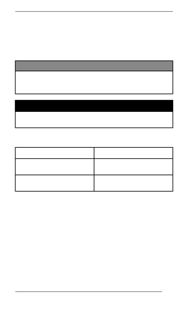
Track Profile Height
Maximum Sustained Speed
57 mm (2.25 in)
110 km/h (70 MPH)
60 mm (2.36 in)
64 mm (2.52 in)
95 km/h (60 MPH)
75 mm (3 in)
141
TUNE YOUR RIDE
Snowmobile handling and comfort depend upon multiple adjustments.
WARNING
Suspension adjustment could affect vehicle handling. Always
take time to familiarize yourself with the vehicle''s behavior after
any suspension adjustment have been made. Always adjust LH
and RH suspension components to the same setting.
Choice of suspension adjustments vary with carrying load, operator's
weight, personal preference, riding speed and field condition.
NOTE:
Some adjustments may not apply to your snowmobile.
WARNING
Before proceeding with any suspension adjustment, remember:
– Park in a safe place.
– Remove the tether cord cap from the engine cut-off switch.
– Use appropriate lifting device or have assistance to share
lifting stress. If a lifting device is not used, use proper lifting
techniques, notably using your legs force.
– Do not attempt to lift the front or rear of vehicle if it is above
your limits.
– Support front of vehicle off the ground with a suitable device
before adjusting suspension.
– Support rear of vehicle off the ground with a wide-base
snowmobile stand with a rear deflector panel.
– Make sure support device is stable and secure.
The best way to set up the suspension is to customize each adjust-
ment one at a time. Various adjustments are interrelated. It may be
necessary to readjust center spring after adjusting front springs for in-
stance. Test run the snowmobile under the same conditions; trail,
speed, snow, operator riding position, etc. Proceed methodically until
you are satisfied.
Following are guidelines to fine-tune suspension. Use suspension ad-
justment tool provided in the tool kit.
Front Suspension Adjustments
Ski Stance
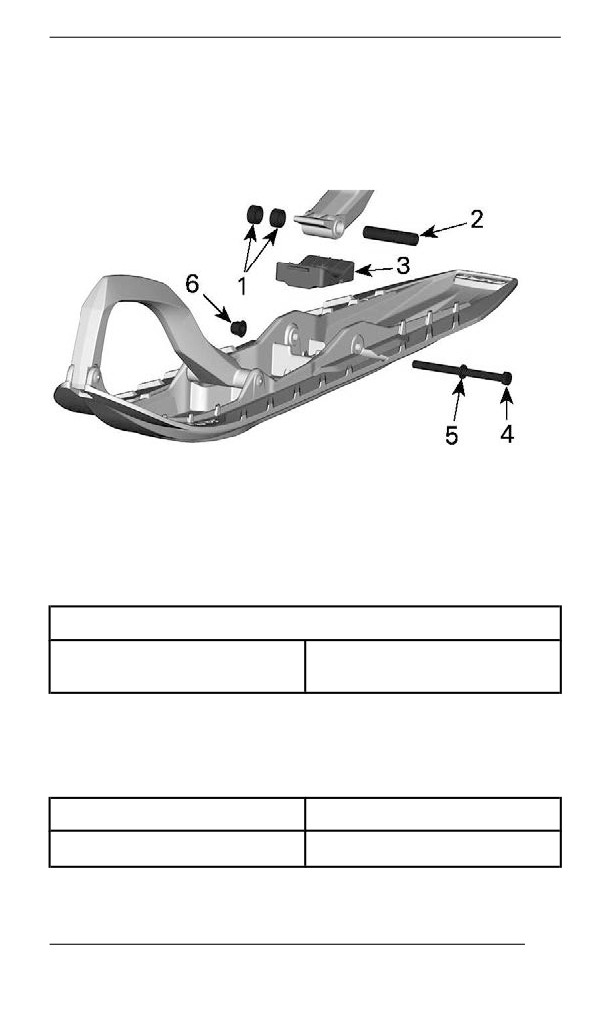
Skis can be set to three different widths.
To obtain the different widths, place the spacers:
142
TUNE YOUR RIDE
- Inside the skis leg (narrowest ski stance setting: easiest to initiate
turn on sidehills), or
- Outside the skis leg (widest ski stance setting: most stable on cor-
ners), or
- On each side (central setting: best steering accuracy on deep
snow).
1. Spacers
2. Axle
3. Stopper
4. Screw
5. Washer
6. Nut
TIGHTENING TORQUE
48 ± 6 Nm
Ski nut
(35 ± 4 lbf-ft)
Front Springs
Front spring preload has an effect on front suspension firmness.
Front spring preload also has an effect on the steering behavior.
Action
Result
Increasing preload
Firmer front suspension
143
TUNE YOUR RIDE
Action
Result
Higher front end
More precise steering
More bump absorption
capability
Softer front suspension
Lower front end
Decreasing preload
Lighter steering
Less bump absorption
capability
WARNING
Adjust both springs to the same preload. Uneven adjustment
can cause poor handling and loss of stability, and/or control,
and increase the risk of an accident.
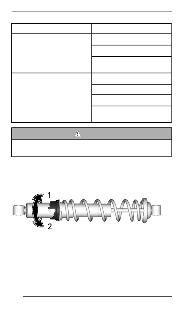
Cam Type Adjuster
Using the suspension adjustment tool provided in the tool kit, turn the
cam to increase or decrease the spring preload.
1. Increase preload
2. Decrease preload
Ring Adjuster – Type 1
Grab and turn the ring and the spring to increase or decrease the
spring preload.
144