Vauxhall Grandland X (2023 year). Manual in english - page 8
 

  Index      Manuals     Vauxhall Grandland X (2023 year). Manual in english


Search            copyright infringement  


Content      ..     6      7      8      9     ..


Vauxhall Grandland X (2023 year). Manual in english - page 8


230

Driving and operating

The screen in the Info Display is

divided into two parts. On the right

there is a view from above the vehicle

and on the left there is the view from

the rear or the front displayed. If the

vehicle is equipped with ultrasonic

parking sensors, they complete the

information on the view from above

the vehicle.

Activation

The panoramic view system is

activated by:

● engaging a gear or gearbox in a

neutral position (front view)

● engaging reverse gear (rear

view)

● manual activation in the Info

Display when driving not more

than 12 mph

Functionality

Different views can be selected in the

left part of the display. Change the

type of view at any time during a

manoeuvre by touching the touch

field in the left lower zone of the

display and selecting a view from the

view selection menu:

● Standard view
● Auto mode
● Zoom view
● 180° view

The display is immediately updated

with the type of view selected.

The state of the system is not kept in

memory when the ignition is switched

off.

Standard view

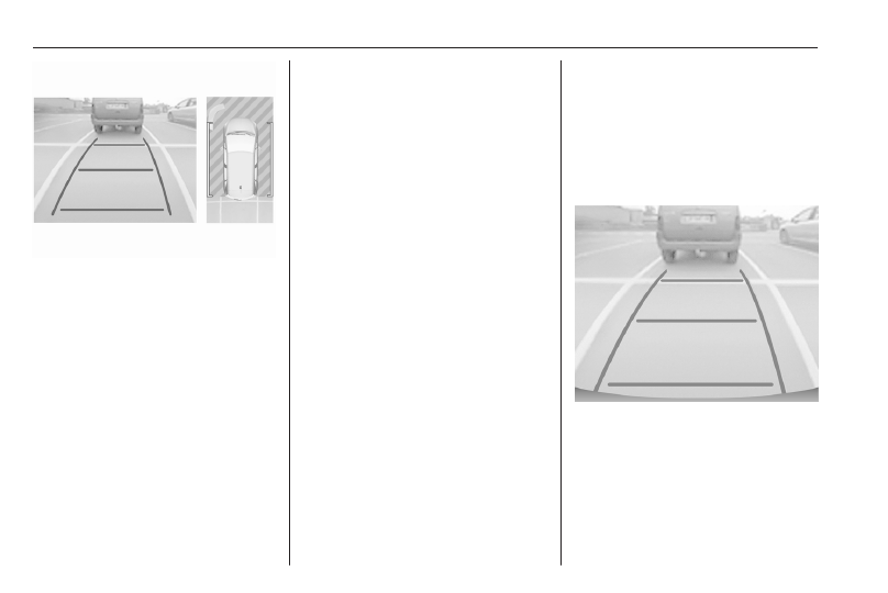
The standard view consists of a rear

view and a front view.
Rear view

The area behind the vehicle is

displayed in the screen. The vertical

lines represent the width of the

vehicle with mirrors unfolded. The

direction of the lines changes with the

position of the steering wheel.

Driving and operating

231

The first horizontal line represents a

distance of about 30 cm beyond the

edge of vehicle's rear bumper. The

upper horizontal lines represent

distances of about 1 m and 2 m.
This view is available in auto mode or

in the view selection menu.
Front view

The area in front of the vehicle is

displayed in the screen. The vertical

lines represent the width of the

vehicle with mirrors unfolded. The

direction of the lines changes with the

position of the steering wheel.
The first horizontal line represents a

distance of about 30 cm beyond the

edge of vehicle's front bumper. The

upper horizontal lines represent

distances of about 1 m and 2 m.
This view is available in auto mode or

in the view selection menu.

Auto mode

This mode is activated by default. If

the vehicle is equipped with ultrasonic

parking sensors, the automatic view

changes from rear view or front view

to a view from above, as an obstacle

is approached during a manoeuvre.

If the vehicle is not equipped with

ultrasonic parking sensors, the view

needs to be changed manually in the

Info Display.

Zoom view

The camera records the vehicle's

surroundings during the manoeuvre

in order to reconstruct a view from

above the rear or the front of the

vehicle in its near surroundings.Thus,

the vehicle can be manoeuvred

around obstacles nearby. This view is

available with auto mode or in the

view selection menu.

180° view

The 180° view facilitates reversing

out of a parking bay, making it

possible to see the approach of

vehicles, pedestrians and cyclists.

This view is not recommended for

carrying out a complete manoeuvre.

It is made up of three areas: left 1,

centre 2 and right 3. This view is

available from the view selection

menu only.

232

Driving and operating

Deactivation

Panoramic view system is

deactivated when:

● driving faster than 12 mph
● seven seconds after disengaging

reverse gear

● by touching the icon 

q

 in the left

upper corner of the touchscreen

● opening the tailgate

System limitations

Caution

For optimal operation of the

system, it is important to keep the

lenses of all cameras always

clean. For the rear view camera,

there is a washer nozzle which will

be activated when the rear window

washer is operating.
If manually cleaning the lenses of

the cameras, rinse the lenses with

water and wipe with a soft cloth.
Do not clean the lenses with a

steam-jet or high-pressure jet

cleaner.

The panoramic view system may not

operate properly when:

● The surrounding is dark.
● The sun or the beam of

headlights is shining directly into

the camera lenses.

● Weather limits visibility, such as

fog, rain, or snow.

● The camera lenses are blocked

by snow, ice, slush, mud, dirt.

● The vehicle is towing an

electrically connected trailer,

bicycle carrier, etc.

● The vehicle had an accident.

Contact a workshop.

● There are extreme temperature

changes.

Caution

It is very important that any repair

to the panoramic view system is

performed accurately according to

Vauxhall specifications.

Otherwise, the system may not

work properly and there is a risk of

unexpected behaviour and / or

messages from the system.

Rear view camera

The rear view camera assists the

driver when reversing by displaying a

view of the area behind the vehicle.
The view of the camera is displayed

in the Info Display.

9

Warning

The rear view camera does not

replace driver vision. Note that

objects that are outside the

camera's field of view and the

parking assist sensors, e.g. below

the bumper or underneath the

vehicle, are not displayed.
Do not reverse or park the vehicle

using only the rear view camera.
Always check the surrounding of

the vehicle before and during

driving.

Driving and operating

233

Switching on

Rear view camera is automatically

activated when reverse gear is

engaged.

Functionality

The camera is mounted in the

tailgate.
The area displayed by the camera is

limited. The distance of the image that

appears on the display differs from

the actual distance.

Guidelines

Dynamic guidelines are horizontal

lines at 1 m intervals projected onto

the picture to define the distance to

displayed objects.

Trajectory lane of the vehicle is

shown in accordance with the

steering angle.

Switching off

The camera is switched off when a

forward gear is engaged.

System limitations

The rear view camera may not

operate properly when:

● the surrounding is dark
● the beam of headlights is shining

directly into the camera lenses

● weather limits visibility, such as

fog, rain, or snow

● the camera lenses are blocked

by snow, ice, slush, mud, dirt.

Clean the lense, rinse with water,

and wipe with a soft cloth

● the tailgate will be opened
● the vehicle is towing an

electrically connected trailer,

bicycle carrier, etc.

● the vehicle had a rear end

accident

● there are extreme temperature

changes

234

Driving and operating

Traffic sign assistant

9

Warning

The actual traffic sign always

takes priority over the traffic sign

displayed in the Driver Information

Centre.

Depending on version, are two

different systems available.

Speed limit system 1

Using the camera at the top of the

windscreen and the vehicle's

integrated navigation system, this

system provides speed limits and end

of speed limits in the Driver

Information Centre.
The system can be activated or

deactivated in the vehicle

personalisation 

3

 89.

If the system is activated but does not

detect a speed limit sign, the following

sign is displayed:

If the vehicle exceeds the speed limit

by at least 3 mph, the speed limit

displayed flashes about ten seconds.
Speed limiter 

3

 205.

Cruise control 

3

 203.

Adaptive cruise control 

3

 207.

Updating navigation map data

To maintain the performance of the

system, the navigation map should be

updated in periodical intervals. A

navigation map update is available

twice per year.
Further information is avaialble in the

Infotainment system section.

Speed limit system 2

This system displays permanently

speed limit information in the Driver

Information Centre.

Providing the speed limit information

involves the following systems:

● camera at the top of the

windscreen

● vehicle's integrated navigation

system

● telematics service

If travelling on a road with no speed

restrictions, e.g., on German

motorways, the following sign is

displayed:

If no speed limit information can be

provided, the following sign is

displayed:

Driving and operating

235

If a new speed limit is provided, a

confirmation chime is given. The

confirmation chime can be activated /

deactivated in the vehicle

personalisation 

3

 89.

If the vehicle exceeds the speed limit,

the speed limit displayed after some

time in the Driver Information Centre

flashes and an audible signal is given

after some time. Time of occurrence

varies. Both flashing and audible

signal are terminated after a few

seconds. Due to legal requirements,

the audible signal can only be

deactivated in the vehicle

personalisation until the next time the

ignition is switched on. If the audible

signal is deactivated, 

4

 illuminates

for a few seconds.
In case of a failure, 

4

 illuminates

permanently. Consult a workshop.
Speed limiter 

3

 205.

Cruise control 

3

 203.

Adaptive cruise control 

3

 207.

Operation conditions

To provide country-specific speed

limit information, the vehicle needs to

identify the country it is currently in. If

a corresponding country list is

available in the Info Display, the

respective country has to be selected

manually. Otherwise, the country is

automatically selected.
To get valid speed limit information,

the vehicle's current position is sent

via the telematics unit and is

immediately deleted after processing.

Tracking of the vehicle position is not

possible at any time.
This is not impacted by the privacy

settings of Vauxhall Connect.

Notice

It is possible to report a permanent

speed limit misinformation on our

website.

Updating data

To maintain the performance of the

system, the vehicle software and the

navigation map should be updated in

periodical intervals.

A navigation map update is available

at least once per year. Further

information is available in the

Infotainment system section.
For vehicle software update consult a

workshop.

Other traffic signs

The system detects traffic signs and

displays them in specific page of the

Driver Information Centre.

This system can be activated or

deactivated in the vehicle

personalisation 

3

 89.

Driver Information Centre 

3

 84.

System limitations

Traffic sign assistant may not operate

properly when:

● Driving on winding or hilly roads.
● Driving during nighttime.

236

Driving and operating

● Driving with snow chains.
● Driving with a trailer.
● The area of the windscreen,

where the front camera is

located, is not clean or affected

by foreign items, e.g. stickers.

● The visibility is limited because of

the weather, such as fog, rain, or

snow.

● The sun is shining directly into

the camera lens.

● Traffic signs are completely or

partially covered or difficult to

discern.

● Traffic signs are incorrectly

mounted or damaged.

● Traffic signs do not comply with

the Vienna Convention on Road

Signs and Signals.

● The navigation map data is

outdated.

Caution

The system is intended to help the

driver within a defined speed

range to recognise certain traffic

signs. Do not ignore traffic signs

which are not displayed by the

system.
Do not let this special feature

tempt you into taking risks when

driving.
Always adapt speed regarding

road, traffic and weather

conditions.
The driver assistance systems do

not relieve the driver from full

responsibility for vehicle

operation.
When driving abroad make sure

the vehicle uses the speed unit of

the respective country. If

necessary, select the correct units

in the Info Display.

Lane departure warning

The lane departure warning system

supports the driver to avoid

unintended leaving of the lane. The

front camera observes road edges,

as well as the lane markings between

which the vehicle is driving. If the

vehicle approaches a road edge or a

lane marking, the system warns the

driver.
Unintended lane departure is not

assumed by the system when the turn

lights are operated and during few

seconds after turn lights have been

switched off.
No warning will be issued with a

dynamic driving, i.e. pressure on the

brake or accelerator pedal.
When the system recognises an

unintended lane departure, the

control indicator 

)

 flashes yellow.

Simultaneously a chime sound is

activated.

There is no lane departure warning

when the turn lights are operated and

during 20 seconds after turn lights

have been switched off.

Driving and operating

237

9

Warning

This system is a driving aid that

cannot, in any circumstances,

replace the need for vigilance on

the part of the driver.

Activation

After ignition is switched on, the lane

departure warning system is

activated. If the system is activated,

the LED in the button 

½

 is not

illuminated. To activate the system if

the system is deactivated, press 

½

.

The system is only operable at

vehicle speeds above 40 mph and if

lane markings are available.

Deactivation

To deactivate the system, press and

hold 

½

. The LED in the button is

illuminated and 

½

 illuminates yellow in

the Driver Information Centre.
At speeds below 37 mph the system

is inoperable.

Fault

In the event of a fault, 

C

 appears in

the Driver Information Centre,

accompanied by a display message

and a warning chime. Seek the

assistance of a workshop.

System limitations

The system performance may be

affected by:

● blocked camera by snow, ice,

slush, mud, dirt, windscreen

damage or affected by foreign

items, e.g. stickers

● close vehicles ahead
● banked roads

● winding or hilly roads
● poor lighting conditions
● sudden lighting changes
● shining sun directly into the

camera lens

● adverse environmental

conditions, e.g. heavy rain, fog,

or snow

● vehicle modifications, e.g. tyres
● roads with poor lane markings

Lane keep assist

Lane keep assist supports the driver

to avoid unintended leaving of the

lane. The front camera observes road

edges, as well as the lane markings

between which the vehicle is driving.

If the vehicle approaches a road edge

or a lane marking, the steering wheel

is gently turned so that the vehicle

turns back into the lane. The driver

will notice a turning movement of the

steering wheel. Turn steering wheel

in same direction, if the system does

not steer sufficiently. Turn steering

wheel gently into opposite direction, if

lane change is intended.

238

Driving and operating

When the system steers to correct the

trajectory of the vehicle, 

a

 flashes

yellow in the Driver Information

Centre.
Unintended lane departure is not

assumed by the system when the turn

lights are operated and during few

seconds after turn lights have been

switched off.
If the system detects that the steering

wheel is not held permanently, it

interrupts the correction after a few

seconds.
When hands-off driving is detected

during a correction a warning

message appears in the Driver

Information Centre, accompanied by

a warning chime. Every further

hands-off detection prolongs the

warning chime duration.
A lane departure warning in the Driver

Information Centre alerts when the

system cannot hold the vehicle within

the lane and immediate driver´s

action is required.

Notice

The system may be switched off if it

detects lanes which are too narrow,

too wide or too curved.

Following preconditions have to be

fulfilled that the system corrects:

● vehicle speed must be between

40 mph and 112 mph

● the turn lights are not activated
● the electronic stability control is

activated and not in operation

● no plug is connected to the power

outlet of the trailer hitch

● no dynamic driving, i.e. pressure

on the brake or accelerator pedal

● roads with good lane markings
● no temporary spare wheel is

used

● the vehicle is not driven in a tight

corner

● no system fault is present which

prevents corrections

Only lane departure warning system

is active, when a system fault is

present, a spare wheel used, or e.g.

a trailer is attached.

Lane departure warning 

3

 236.

Activation

Depending on version, the system is

automatically activated when ignition

is switched on. If the system is

activated, the LED in the button 

j

 is

not illuminated. To activate the

system when the system is

deactivated, press 

j

.

Deactivation

To deactivate the system, press 

j

until LED in the button is illuminated.

Driving and operating

239

Fault

In the event of a fault, 

a

 and 

C

appear in the Driver Information

Centre, accompanied by a display

message and a warning chime. Seek

the assistance of a workshop.

System limitations

The system performance may be

affected by:

● covered camera by snow, ice,

slush, mud, dirt, or affected by

windscreen damage or foreign

items, e.g. stickers

● close vehicles ahead
● banked roads
● winding or hilly roads
● poor lighting conditions
● sudden lighting changes
● shining sun directly into the

camera lens

● adverse environmental

conditions, e.g. heavy rain, fog,

or snow

● vehicle modifications, e.g. tyres
● roads with poor lane markings

A warning message may appear

when the vehicle is travelling in a long

straight lane on a smooth road

surface even if the driver is holding

the steering wheel properly.
Deactivate the system if the system is

disturbed by tar marks, shadows,

road cracks, temporary or

construction lane markings, or other

road imperfections.

9

Warning

Always keep your attention on the

road and maintain proper vehicle

position within the lane, otherwise

vehicle damage, injury or death

could occur.
The system may not keep the

vehicle in the lane or give an alert,

even if a lane marking is detected.
The steering of the system may

not be sufficient to avoid a lane

departure.
The system may not detect hands-

off driving due to external

influences (road condition and

surface, weather etc). The driver

has full responsibility to control the

vehicle and is always required to

keep the hands on the steering

wheel while driving.
Using the system while towing a

trailer or on slippery roads could

cause loss of control of the vehicle

and a crash. Switch the system off.

Advanced lane keep assist

9

Warning

The system assists the driver in

managing the steering,

acceleration and braking within

the limits of the laws of physics

and the capabilities of the vehicle.

Some road infrastructure

elements or vehicles present on

the road may not be properly seen

or may be poorly interpreted by the

camera and radar, which may lead

to an unexpected change in

direction, a lack of steering

correction and/or inappropriate

management of the acceleration

or braking.

240

Driving and operating

Advanced lane keep assist is an

enhancement of the lane keep assist

system.

The activated system observes the

lane markings by using the camera

located at the top of the windscreen.

It steers the vehicle inside the

detected lane. The driver will notice a

turning movement of the steering

wheel.

Thus, the current position of the

vehicle within the lane is kept.
When the vehicle is steered by the

system, 

O

 illuminates green in the

Driver Information Centre.
However, the control of the vehicle

can be taken over at any time by the

driver. Therefore, the driver needs to

apply some additional force when

turning the steering wheel.
If the system detects that the driver is

not holding the steering wheel firmly

enough, it triggers a series of gradual

alerts. If the interruption takes too

long, the system will be deactivated.

O

 extinguishes in the Driver

Information Centre. The system has

to be reactivated again by the driver.
Adaptive cruise control 

3

 207.

Required preconditions

● Adaptive cruise control must be

activated.

● The driver must hold the steering

wheel.

● The turn lights are not activated.

● The Electronic Stability Control is

activated and not in operation.

● No plug is connected to the

power outlet of the trailer hitch.

● No dynamic driving is detected,

i.e. pressure on the brake or

accelerator pedal.

● Roads have good lane markings.
● No temporary spare wheel is

used.

● The vehicle is not driven in a tight

corner.

● No system fault is present which

prevents corrections.

Activation

Driving and operating

241

Press 

C

 to activate the system. The

LED in the button is illuminated and

O

 illuminates green in the Driver

Information Centre if lane marking are

detected.

Deactivation

To deactivate the system, press 

C

.

The LED in the button and 

O

 in the

Driver Information Centre are

extinguished.

Pausing / suspending the system

Advanced lane keep assist may be

paused or suspended in the following

situations:

● The Electronic Stability Control is

in operation or it has been

deactivated.

● At least one of the lane markings

is not detected by the system for

several seconds. The system will

be reactivated once the operating

conditions are regained.

● The turn lights are activated.
● Driving outside the lane limits.
● The steering wheel is held too

tight or moved too dynamically.

● The brake pedal or the

accelerator pedal are applied.

● The adaptive cruise control is

paused.

● The road is too narrow or wide.
● The lateral acceleration in curves

is too high.

O

 illuminates grey in the Driver

Information Centre.

Fault

In the event of a fault, 

O

 and 

C

appear in the Driver Information

Centre, accompanied by a display

message and a warning chime. Seek

the assistance of a workshop.

System limitations

The system performance may be

affected by:

● covered camera by snow, ice,

slush, mud, dirt, or affected by

windscreen damage or foreign

items, e.g. stickers

● close vehicles ahead
● banked roads
● winding or hilly roads

● poor lighting conditions
● sudden lighting changes
● shining sun directly into the

camera lens

● adverse environmental

conditions, e.g. heavy rain, fog,

or snow

● vehicle modifications, e.g. tyres
● roads with poor lane markings

A warning message may appear

when the vehicle is travelling in a long

straight lane on a smooth road

surface even if the driver is holding

the steering wheel properly.
Deactivate the system if the system is

disturbed by tar marks, shadows,

road cracks, temporary or

construction lane markings, or other

road imperfections.

242

Driving and operating

9

Warning

Always keep your attention on the

road and maintain proper vehicle

position within the lane, otherwise

vehicle damage, injury or death

could occur.
The system may not keep the

vehicle in the lane or give an alert,

even if a lane marking is detected.
The steering of the system may

not be sufficient to avoid a lane

departure.
The system may not detect hands-

off driving due to external

influences (road condition and

surface, weather etc). The driver

has full responsibility to control the

vehicle and is always required to

keep the hands on the steering

wheel while driving.
Using the system while towing a

trailer or on slippery roads could

cause loss of control of the vehicle

and a crash. Switch the system off.

Driver alert

The driver alert system monitors the

driving time and the vigilance of the

driver. Monitoring the vigilance of the

driver is based on the trajectory

variations of the vehicle compared to

the lane markings.
The system cannot replace the need

for vigilance on the part of the driver.

Taking a break is recommended as

soon as feeling tired or at least every

two hours. Do not drive when feeling

tired.

Activation or Deactivation

The system can be activated or

deactivated in the Info Display 

3

 85.

When the system is deactivated 

2

may illuminate in the Driver

Information Centre.
The system is automatically activated

when ignition is switched on.

Driving time alert

The driver gets notified by a pop-up

reminder symbol 

 in the Driver

Information Centre simultaneously

with an acoustic alert if the driver has

not taken a break after two hours of

driving at a speed above 40 mph. The

alert is repeated hourly until the

vehicle is stopped, no matter how

vehicle speed evolves.
The counting of driving time alert is

reset when the ignition has been

switched off for a few minutes.

Driver drowsiness detection

The system monitors the driver's level

of vigilance at speeds above 40 mph.

A camera at the top of the windscreen

detects variations in trajectory

compared to the lane markings.
The system may perform a learning

procedure for up to 30 minutes after

the start of the monitoring. During this

period, the driver's individual driving

behaviour is analysed and no alert is

given.
If the trajectory of the vehicle

suggests a certain level of

drowsiness or inattention by the

driver, the system triggers the first

level of alert. The driver is notified by

a message and an audible signal is

given.

Driving and operating

243

After three first level alerts, the

system triggers a new alert with a

message, accompanied by a more

pronounced audible signal.
The driver drowsiness detection is

reinitialised in the following situations:

● the ignition has been switched off

for a few minutes

● the speed remains below

40 mph for a few minutes

● the driver's seat belt has been

unfastened and the driver's door

has been opened

System limitations

In the following situations, the system

may not operate properly or even not

operate at all:

● poor visibility caused by

inadequate lighting of the

roadway, falling snow, heavy

rain, dense fog etc.

● dazzle caused by headlamps of

oncoming vehicles, low sun,

reflections on damp roads,

leaving a tunnel, alternating

shade and light etc.

● no lane markings detected or

multiple lane markings due to

roadworks

● close vehicles ahead
● winding roads or narrow roads
● advanced lane keep assist is

active

● covered camera by snow, ice,

slush, mud, dirt, or affected by

windscreen damage or foreign

items, e.g. stickers, 

2

 may

appear in the Driver Information

Centre, accompanied by a

message

● in the event of a system fault,

2

 may appear in the Driver

Information Centre,

accompanied by a message and

a warning chime

Charging

General information

9

Warning

Persons with a pacemaker should

consult a doctor for possible

precautions.

Charging the vehicle's high voltage

battery depends upon several factors:

● high voltage battery of the vehicle
● internal onboard charger (OBC)
● external charging device
● charging cable

The charging cable connects the

vehicle with an external charging

device providing electric power. This

244

Driving and operating

may be a domestical electric outlet, a

Green'Up socket, a wall box or a

public charging station.
The high voltage battery is charged

with direct current (DC) only. When

charging the vehicle alternating

current (AC) has to be converted into

DC. This is done by the vehicle's

onboard charger. The single-phase

onboard charger is available with

3.7 kW or 7.4 kW.
The speed of charging the vehicle's

high voltage battery depends upon

the weakest element of the charging

chain. To achieve the maximum

charging speed, charging cable and

charging device have to be attuned to

each other.
Charging types 

3

 244.

Charging cable 

3

 251.

Electric power consumption and

range

The electric power consumption

(combined) is within a range of 17.5

to 16.5 kWh/100 km.
The range is up to 40 miles.

For the values specific to your

vehicle, refer to the EEC Certificate of

Conformity provided with your vehicle

or other national registration

documents.
The determination of electric power

consumption is regulated by directive

R (EC) No. 715/2007 and No.

2017/1151 (in the latest applicable

version).

Charging types

There are different types of charging

the vehicle's high voltage battery.

Charging times refer to charging an

empty battery until it is completely

charged.

Charging at wall boxes / AC

charging stations

A wall box / AC charging station may

provide a charging cable which has to

be connected to the vehicle's

charging port.
Charging time takes approx. three

hours and 25 minutes with the

3.7 kW onboard charger and 16 A.

For the 7.4 kW onboard charger with

32 A, charging time takes approx. one

hour and 40 minutes.

Charging at Green'Up outlets

Connect the charging cable to the

vehicle's charging port and to the

Green'Up outlet.
Charging time takes approx. three

hours and 55 minutes.

Charging at domestic electric

outlets

Connect the charging cable to the

vehicle's charging port and to the

domestic electric outlet.
Charging time may take approx. eight

hours with a charging power of 1.8

kW.

Driving and operating

245

Charging cable

Depending on the charging type,

different charging cables are used.

9

Warning

Improper use of portable charging

cables may cause a fire, electric

shock, or burns, and may result in

damage to property, serious

injury, or death.

● Do not use extension cables,

multi-outlet power strips,

splitters, grounding adaptors,

surge protectors, or similar

devices.

● Do not use an electric socket

that is worn or damaged, or one

that will not hold the plug firmly

in place.

● Do not immerse the charging

cable into any liquid.

● Do not use an electric socket

that is not properly grounded.

● Do not use an electric socket

that is on a circuit with other

electric loads.

9

Warning

Read all the safety warnings and

instructions before using this

product. Failure to follow the

warnings and the instructions may

result in electric shock, fire, and /

or serious injury.
Never leave children unattended

near the vehicle while the vehicle

is charging and never allow

children to play with the charging

cable.
If the plug provided does not fit the

electric outlet, do not modify the

plug. Arrange for a qualified

electrician to inspect the electric

outlet.
Do not put fingers into the electric

vehicle connector.

9

Danger

There is a risk of electric shock

that may cause personal injury or

death.

Do not use the charging cable if

any part of the charging cable is

damaged.
Do not open or remove the

charging cable cover.
Service by qualified personnel

only. Connect the charging cable

to a properly grounded outlet with

cables that are not damaged.

246

Driving and operating

Basic domestic cable (mode 2) /

enhanced domestic cable (mode

2)

1. Vehicle plug
2. Status indicators
3. Wall plug

Basic domestic cables (mode 2) are

used for charging at domestic electric

outlets. A basic domestic cable

(mode 2) consists of a vehicle plug, a

control box and a plug for the

domestic electric outlet. The control

box has an intergrated charge

controller and several LEDs

indicating the charging status.

Enhanced domestic cables (mode 2)

are similar to basic domestic cables

(mode 2). However, the charging

performance of enhanced domestic

cables (mode 2 charging) is better

than the charging performance of

basic domestic cables (mode 2).

Enhanced domestic cables (mode 2)

are used at Green'Up sockets which

have to be installed by a certified

electrician at the customer's site.

Charging cable status indicators

After plugging in the charging cable,

it will perform a quick self test and all

status indicators illuminate for a

moment. For the functions of the

status indicators, refer to the manual

of the charging cable manufacturer.

Important information about

portable electric vehicle charging

● Charging an electric vehicle can

stress a building's electrical

system more than a typical

household appliance.

● Before you plug in to any electric

outlet, have a qualified electrician

inspect and verify the electrical

system (electric outlet, wiring,

junctions and protection devices)

for heavy-duty service at a 10 A

continuous load.

● Electric outlets may wear out with

normal usage or be damaged

over time, making them

unsuitable for electric vehicle

charging.

● Check the electric outlet / plug

while charging and discontinue

use if the electric outlet / plug is

hot, then have the electric outlet

serviced by a qualified

electrician.

● When outdoors, plug into an

electric outlet that is weather-

proof while in use.

● Mount the charging cable to

reduce strain on the electric

outlet / plug.

Driving and operating

247

Mode 3 charging cable

1. Vehicle plug
2. Plug for wall box / AC charging

station

Mode 3 charging cables are used for

charging at wall boxes and AC

charging stations. A mode 3 charging

cable provides a vehicle plug and a

plug for the wall box / AC charging

station. Wall boxes / AC charging

stations may provide an integrated

mode 3 charging cable. For more

information on the mode 3 charging

cable, refer to the manual of the

charging cable manufacturer.

Charging

9

Warning

Persons with a pacemaker or

similar devices should consult a

doctor for possible precautions.
If in doubt, during charging do not

remain inside or near the vehicle,

near the charging cable or the

charging unit.

In order to ensure the compatibility of

plug and outlet, a label is used. The

label is located on the inside of the

vehicle's charging port flap. Make

sure to connect only a cable of the

same type.

Type 2 plug or outlet used for AC

charging.

9

Warning

Avoid any entry of fluids into the

charging port of the vehicle, the

vehicle plug of the charging cable

and the domestic electric outlet.

If charging at a public AC charging

station, follow the instructions for the

use of the respective charging

station. Public AC charging stations

may not provide an integrated

charging cable. In this case, a

portable mode 3 charging cable is

required.

9

Warning

Do not work in the engine

compartment. Some areas remain

very hot, even an hour after

charging and the fan may start at

any time.

248

Driving and operating

9

Warning

If charging at a domestic electric

outlet, only use an outlet which is

properly grounded and protected

by a 30 mA differential switch.
Only use a domestic electric outlet

protected by a circuit breaker

adapted to the amperage of the

electric circuit.
Have a qualified electrician check

the electric installation to be used.

The installation has to be in

compliance with national

standards and compatible with the

vehicle.
If using a dedicated domestic

electric outlet, have it installed by

a qualified electrician.
Make sure that the electric outlet,

the plug and the cable do not

support the weight of the control

box.

1. Shift into P and switch off the

vehicle.

2. Push the charging port flap to

release it.

3. If necessary, take the charging

cable out of the load

compartment.

4. If necessary, plug in the plug of

the charging cable into the

corresponding port of the external

power source.
Charging cable 

3

 251.

5. If necessary, remove the

protective cover from the vehicle

plug of the charging cable.

6. Plug in the vehicle plug of the

charging cable into the charging

port of the vehicle.
Charging status 

3

 250.

Driving and operating

249

The start of charging is indicated by

the green flashing of the status

indicator at the charging port and at

the control box of the charging cable

if available.

Once charging, the vehicle plug will

be locked to the charging port and

cannot be disconnected while

charging is active. 

-

 indicator

illuminates.
Charging types 

3

 244

Cancelling the charging process

Notice

At public charging stations, the

cancelling and subsequent

resuming of the charging process

may cause additional costs.
Once the charging process has

started, only the driver's door can be

unlocked without cancelling the

charging process. Therefore,

activate the driver's door only

function in the vehicle

personalisation.

Press 

<

 on the remote control to

cancel the charging process at any

time.
Press 

<

 twice to cancel the charging

process at any time if the function

driver's door only is activated in the

vehicle personalisation.
Central locking system 

3

 10.

Vehicle personalisation 

3

 89.

Stop charging

The high voltage battery is fully

charged if the status indicator on the

charging port permanently illuminates

green.

1. Unlock the vehicle before

removing the vehicle plug from

the charging port.
If the vehicle is already unlocked,

lock the vehicle and unlock it

again.

250

Driving and operating

2. Disconnect the vehicle plug of the

charging cable from the charging

port within 30 seconds after

unlocking.

3. Close the charging port flap by

pressing firmly in the centre to

latch properly.

4. Disconnect the charging cable

from the external power source.

5. If necessary, store the charging

cable in the load compartment.

While the charging cable is plugged

into the vehicle, the vehicle cannot be

driven.

Programmable charging

By default, charging starts as soon as

the vehicle plug of the charging cable

is plugged into the charging port of the

vehicle. It is also possible to schedule

charging using the Info Display.
Programmable charging is also

available via the MyVauxhall App.

1. Press 

m

.

2. Select Charge.
3. Press 

/

.

4. Define the number of hours and

minutes after which the loading

process starts.

5. Press OK.
6. Plug in the vehicle.

7. Within one minute, press 

b

 to

activate programmable charging.

8. Depending on version, lock the

vehicle.

Driving and operating

251

The status indicator illuminates blue

indicating that programmable

charging is active.
Charging status 

3

 250.

Charging 

3

 245.

Charging status

If the vehicle is plugged in and the

ignition is switched off, the charging

status indicator indicates the

following:

● Illuminates white: welcome

lighting when charging port flap is

opened

● Illuminates green: charging

complete

● Flashes green: high voltage

battery charging

● Illuminates red: charging fault
● Illuminates blue: programmable

charging active

A charging fault has occured if the

vehicle is plugged in and the charging

status indicator is off.
Further charging status indicators are

located on the control box of the

charging cable.
Charging cable 

3

 251.

Programmable charging 

3

 247.

Fuel

Fuel for petrol engines

Only use unleaded fuel that complies

with European standard EN 228 or

E DIN 51626-1 or equivalent.
The engine is capable of running with

fuel that contains up to 10% ethanol

(e.g. named E10).
Use fuel with the recommended

octane rating. A lower octane rating

can reduce engine power and torque

and slightly increases fuel

consumption.

252

Driving and operating

Caution

Do not use fuel or fuel additives

that contain metallic compounds

such as manganese-based

additives. This may cause engine

damage.

Caution

Use of fuel with a lower octane

rating than the lowest possible

rating could lead to uncontrolled

combustion and engine damage.

The engine specific requirements

regarding octane rating are given in

the engine data overview 

3

 306. A

country-specific label at the fuel filler

flap can supersede the requirement.

In certain countries, the use of a

particular fuel, e.g. a specific octane

rating, may be required to ensure

proper engine operation.

Fuel for diesel engines

The diesel engines are compatible

with bio-fuels that conform to current

and future European standards and

and can be obtained from filling

stations:

Diesel fuel that meets standard

EN590 mixed with a biofuel that

meets standard EN14214 (possibly

containing up to 7% Fatty Acid Methyl

Ester).

Diesel fuel that meets standard

EN16734 mixed with a biofuel that

meets standard EN14214 (possibly

containing up to 10% Fatty Acid

Methyl Ester).

Paraffinic diesel fuel that meets

standard EN15940 mixed with a

biofuel that meets standard

EN14214 (possibly containing up to

7% Fatty Acid Methyl Ester).

The use of B20 or B30 fuel meeting

standard EN16709 is possible in your

diesel engines. However, this use,

even occasional, requires strict

Driving and operating

253

application of the special servicing

conditions referred to as "Arduous

conditions".
For more information, contact a

dealer or a qualified workshop.

Caution

The use of any other type of (bio)

fuel (vegetable or animal oils, pure

or diluted, domestic fuel etc.) is

strictly prohibited (risk of damage

to the engine and fuel system).

Notice

The only diesel additives authorised

for use are those that meet the

B715000 standard.

Low temperature operation

At temperatures below 0 °C, some

diesel products with biodiesel blends

may clog, freeze or gel, which may

affect the fuel supply system. Starting

and engine operation may not work

properly. Make sure to fill winter

grade diesel fuel at ambient

temperatures below 0 °C.

Arctic grade diesel fuel can be used

at extremely low temperatures below

-20 °C. Using this fuel grade in warm

or hot climates is not recommended

and may cause engine stalling, poor

starting or damage on the fuel

injection system.

Refuelling

9

Danger

Before refuelling, switch off

ignition and any external heaters

with combustion chambers.

Follow the operating and safety

instructions of the filling station

when refuelling.

9

Danger

Fuel is flammable and explosive.

No smoking. No naked flames or

sparks.
If you can smell fuel in your

vehicle, have the cause of this

remedied immediately by a

workshop.

A label with symbols at the fuel filler

flap is indicating the allowed fuel

types. In Europe the pump nozzles of

the filling stations are marked with

these symbols. Refuel only the

allowed fuel type.

Caution

In case of misfuelling, do not

switch on ignition.

Fuel filler flap is located at right rear

side of vehicle.

254

Driving and operating

The fuel filler flap can only be opened

if the vehicle is unlocked. Open the

fuel filler flap by pushing the flap.
To open the fuel filler flap of a PHEV,

a depressurisation phase is required

to avoid the emission of fuel vapour.

This can take up to one minute.

Press 

r

. After depressurisation the

fuel filler flap is unlocked and bounces

a bit.

Petrol and diesel refuelling

To open, turn the cap slowly

anticlockwise.

The fuel filler cap can be attached to

the hook on the fuel filler flap.
Place the nozzle in straight position to

the filler neck and press with slight

force to insert.
To refuel, switch on pump nozzle.
After the automatic cut-off, the tank

can be topped up by operating the

pump nozzle a maximum of two more

times.

Driving and operating

255

Caution

Wipe off any overflowing fuel

immediately.

To close, turn the fuel filler cap

clockwise until it clicks.
Close the flap and allow it to engage.

Fuel filler cap

Only use genuine fuel filler caps.
Diesel-engined vehicles have special

fuel filler caps.

Fuel consumption - CO

2

-

Emissions

The fuel consumption (combined) is

within a range of 196 to 36 mpg.
The CO

2

 emission is within a range of

150 to 128 g/km.

General information

For the values specific to your

vehicle, refer to the EEC Certificate of

Conformity provided with your vehicle

or other national registration

documents.
The determination of fuel

consumption is regulated by directive

R (EC) No. 715/2007 and No.

2017/1151 (in the latest applicable

version).
The specification of CO

2

 emission is

also a constituent of the directive.
The figures given must not be taken

as a guarantee for the actual fuel

consumption of a particular vehicle.

Furthermore, fuel consumption is

dependent on personal driving style

as well as road and traffic conditions.
All values are based on the EU base

model with standard equipment.
The calculation of fuel consumption

takes into account the vehicle's kerb

weight, ascertained in accordance

with the regulations. Optional

equipment may result in slightly

higher fuel consumption and

CO

2

 emission levels and a lower

maximum speed.

256

Driving and operating

Trailer hitch

General information

Only use towing equipment that has

been approved for your vehicle. If

using non-factory fitted towing

equipment, deactivation of the hands-

free tailgate operation may be

required 

3

 16.

Entrust retrofitting of towing

equipment to a workshop. It may be

necessary to make changes that

affect the cooling system, heat

shields or other equipment.
The bulb outage detection function for

trailer brake light cannot detect a

partial bulb outage. E.g. in case of

four bulbs with a power of 5 W each,

the function only detects light outage

when only a single 5 W light remains

or none remain.
Trailers equipped with LED lights are

not suitable for the wiring harness of

this trailer hitch.
Fitting of towing equipment could

cover the opening of the towing eye.

If this is the case use the coupling ball

bar for towing. Always keep the

coupling ball bar in the vehicle to have

it on hand if needed.

Driving characteristics and

towing tips

Before attaching a trailer, lubricate

the coupling ball. However, do not do

so if a stabiliser, which acts on the

coupling ball, is being used to reduce

snaking movements.
During trailer towing do not exceed a

speed of 50 mph. A maximum speed

of 60 mph is only appropriate if an

oscillation damper is used and the

permissible gross trailer weight does

not exceed the vehicle's curb weight.
For trailers with low driving stability

and caravan trailers, the use of an

oscillation damper is strongly

recommended.
If the trailer starts snaking, drive more

slowly, do not attempt to correct the

steering and brake sharply if

necessary.
When driving downhill, drive in the

same gear as if driving uphill and

drive at a similar speed.

Adjust tyre pressure to the value

specified for full load 

3

 312.

Trailer towing

Trailer loads

The permissible trailer loads are

vehicle and engine-dependent

maximum values which must not be

exceeded. The actual trailer load is

the difference between the actual

gross weight of the trailer and the

actual coupling socket load with the

trailer coupled.
The permissible trailer loads are

specified in the vehicle documents. In

general, they are valid for inclines up

to 12%.
The permissible trailer load applies

up to the specified incline and at sea

level. Since engine power decreases

as altitude increases due to the air

becoming thinner, therefore reducing

climbing ability, the permissible gross

train weight also decreases by 10%

for every 1000 m of altitude. The

gross train weight does not have to be

Driving and operating

257

reduced when driving on roads with

slight inclines (less than 8%, e.g.

motorways).
The permissible gross train weight

must not be exceeded. This weight is

specified on the identification plate

3

 303.

Vertical coupling load

The vertical coupling load is the load

exerted by the trailer on the coupling

ball. It can be varied by changing the

weight distribution when loading the

trailer.
The maximum permissible vertical

coupling load (70 kg) is specified on

the towing equipment identification

plate and in the vehicle documents.
Always aim for the maximum vertical

coupling load, especially in the case

of heavy trailers. The vertical coupling

load should never fall below 25 kg.

Rear axle load

When the trailer is coupled and the

towing vehicle fully loaded, the

permissible rear axle load (see

identification plate or vehicle

documents) may be exceeded by

60 kg, the gross vehicle weight rating

must not be exceeded. If the

permissible rear axle load is

exceeded, a maximum speed of

60 mph applies.

Towing equipment

Caution

When operating without a trailer,

remove the coupling ball bar.

Fitting the coupling ball bar

Disengage and fold down the socket.

Remove the sealing plug from the

opening for the coupling ball bar and

stow it.

258

Driving and operating

Checking the tensioning of the

coupling ball bar

● Red marking on rotary knob must

point towards green marking on

coupling ball bar.

● The gap between the rotary knob

and the coupling ball bar must be

approx. 6 mm.

● Remove the cover from the lock

of the rotary knob and verify

whether the rotary knob is

locked. If the rotary knob cannot

be turned, it is locked.

Otherwise, the coupling ball bar must

be tensioned before being inserted:

● Unlock coupling ball bar by

turning key to position 

c

.

● Pull out rotary knob and turn

clockwise as far as it will go.

Inserting the coupling ball bar

Driving and operating

259

Insert the tensioned coupling ball bar

in the opening and push firmly

upwards until it audibly engages.
The rotary handle snaps back into its

original position resting against the

coupling ball bar without a gap.

9

Warning

Do not touch rotary handle during

insertion.

Lock the coupling ball bar by turning

the key to position 

e

. Remove the key

and close the protective flap.

Eye for break-away stopping cable

Attach breakaway stopping cable to

eye.

Check that the coupling ball bar is

correctly installed

● Green marking on rotary knob

must point towards green

marking on coupling ball bar.

● There must be no gap between

the rotary handle and the

coupling ball bar.

● The coupling ball bar must be

firmly engaged in the opening.

● The coupling ball bar must be

locked and the key removed.

9

Warning

Towing a trailer is permitted only

when a coupling ball bar is fitted

correctly. If the coupling ball bar

does not engage correctly, seek

the assistance of a workshop.

Dismounting the coupling ball bar

Open the protective flap and turn the

key to position 

c

 to unlock the

coupling ball bar.
Pull out rotary handle and turn

clockwise as far as it will go. Pull out

coupling ball bar downwards.
Insert sealing plug in opening. Fold

away socket.

Trailer stability assist

If the system detects snaking

movements, engine power is reduced

and the vehicle / trailer combination is

260

Driving and operating

selectively braked until the snaking

ceases. While system is working keep

steering wheel as still as possible.
Trailer stability assist is a function of

the Electronic Stability Control 

3

 199.

Vehicle care

261

Vehicle care

General Information ................... 261

Accessories and vehicle

modifications .......................... 261

Vehicle storage ........................ 263

End-of-life vehicle recovery ..... 264

Vehicle checks ........................... 265

Performing work ...................... 265

Bonnet ..................................... 265

Engine oil ................................. 266

Engine coolant ......................... 267

Washer fluid ............................ 268

Brakes ..................................... 268

Brake fluid ............................... 268

Vehicle battery ......................... 269

High voltage battery ................ 271

Diesel fuel system bleeding ..... 272

Wiper blade replacement ........ 272

Bulb replacement ....................... 273

LED headlights ........................ 273

Front fog lights ......................... 273

Tail lights ................................. 273

Side turn lights ......................... 276

Number plate light ................... 276

Interior lights ............................ 276

Electrical system ........................ 277

Fuses ....................................... 277

Vehicle tools .............................. 277

Tools ........................................ 277

Wheels and tyres ....................... 278

Winter tyres ............................. 278

Tyre designations .................... 278

Tyre pressure .......................... 279

Tyre deflation detection

system .................................... 280

Tread depth ............................. 281

Changing tyre and wheel size . 281

Wheel covers ........................... 281

Tyre chains .............................. 282

Tyre repair kit .......................... 282

Wheel changing ....................... 285

Spare wheel ............................ 287

Jump starting ............................. 290
Towing ....................................... 292

Towing the vehicle ................... 292

Towing another vehicle ........... 293

Appearance care ....................... 294

Exterior care ............................ 294

Interior care ............................. 296

Floor mats ............................... 296

General Information

Accessories and vehicle

modifications

We recommend the use of genuine

parts and accessories and factory

approved parts specific for your

vehicle type. We cannot assess or

guarantee reliability of other products

- even if they have a regulatory or

otherwise granted approval.
Any modification, conversion or other

changes made to standard vehicle

specifications (including, without

limitation, software modifications,

modifications of the electronic control

units) may invalidate the warranty

offered by Vauxhall. Furthermore,

such changes may affect driver

assistance systems, may impact fuel

or electric power consumption, CO

2

emissions and other emissions of the

vehicle and cause the vehicle to no

longer conform to the operating

permit, impacting the validity of your

vehicle registration.


Content      ..     6      7      8      9     ..