Airbus A318/A319, A320/A321. Manual (Version 01-03-002) - page 3
Aerosoft
The Airbus A318/319/320/321 in FSX
Vol
06-01-09 Page 61
Airbus A318/319/320/321
Step-By-Step Tutorial
6
25 October 2015
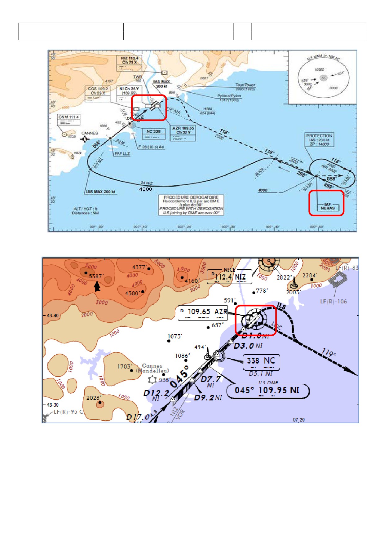
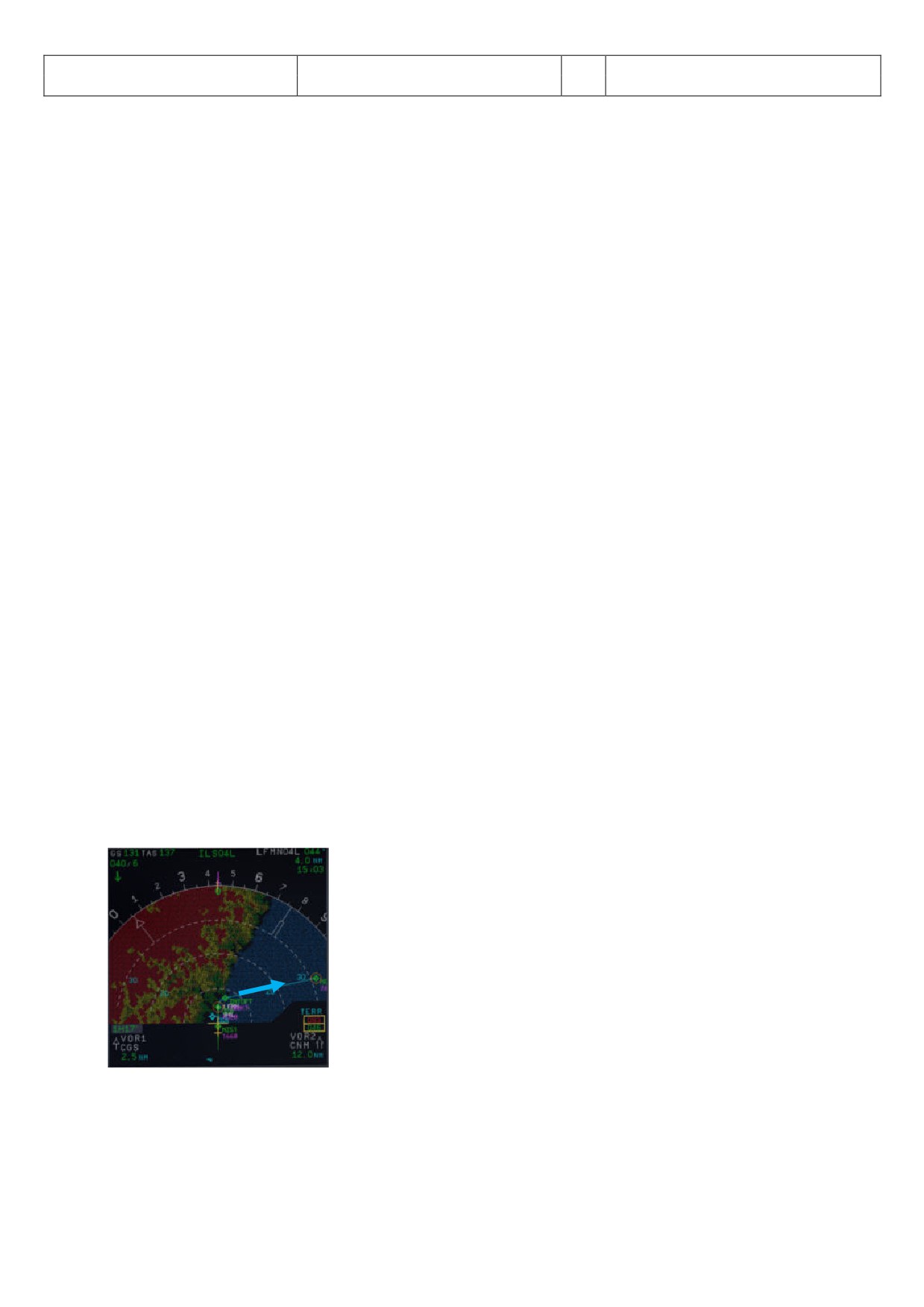
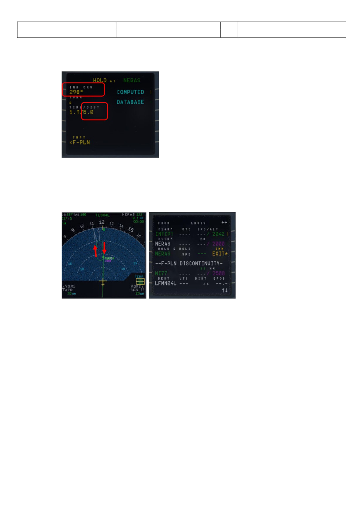
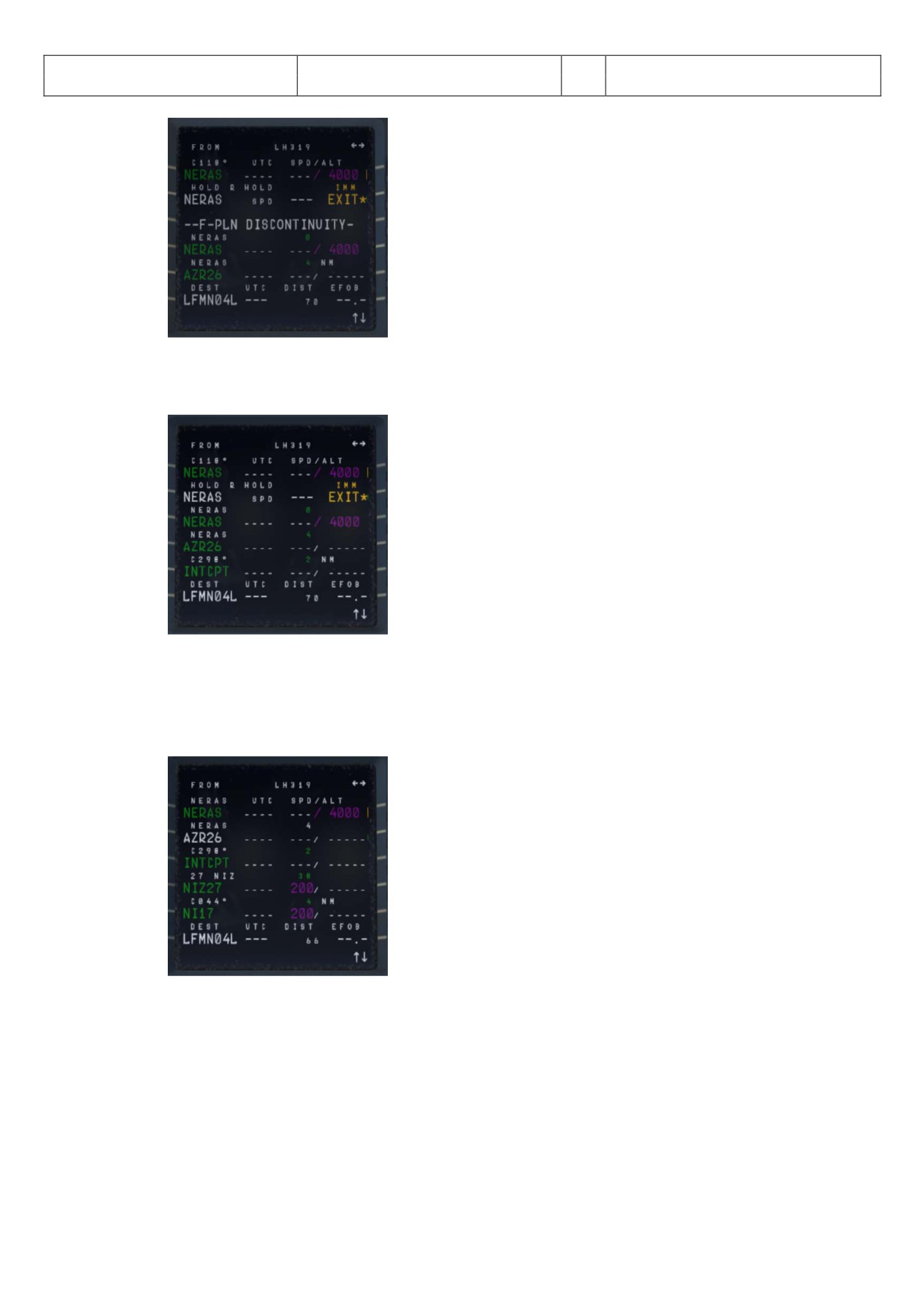
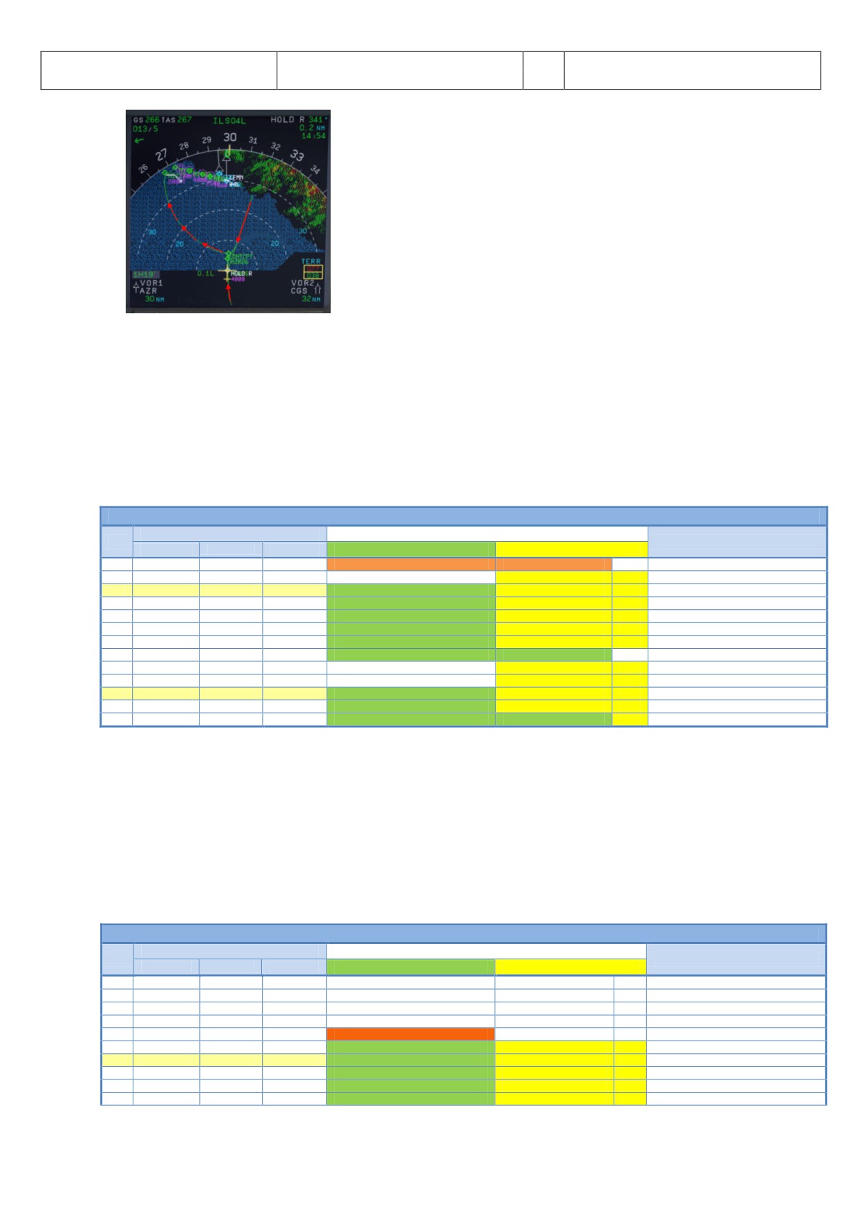
Picture 66: Chart TRANS NERAS
Picture 67: Chart ILS 04L Nice
Aerosoft
The Airbus A318/319/320/321 in FSX
Vol
06-01-09 Page 62
Airbus A318/319/320/321
Step-By-Step Tutorial
6
25 October 2015
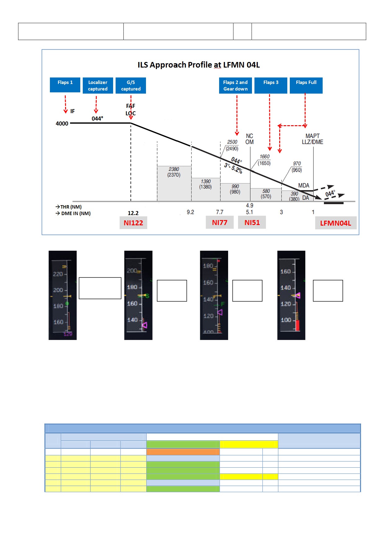
Picture 68: Final Procedure - ILS Approach Profile LFMN04L
Green Dot
S -
F -
Vapp -
Speed
Speed
Speed
Speed
Picture 69: Speeds “Green Dot”, S, F and Vapp on PFD
5.21 Final
There are two main modes for the approach: Using “Managed Speed” or “Selected Speed (manually)”. Our
Checklist- and Copilot-Function uses the “Managed Speed” mode. This means that the speed is automatically
set by the MCDU and the flaps are manually deployed by the Copilot (based on the situation).
The Final CL activation is “independent” from the activation of the MCDU - PERF - APPR mode activation. The
FINAL checklist will be automatically started after the APPR CL has been completed.
FINAL
PANEL
ACTION
NO.
REMARK
TYP
PART (Name)
PART (No.)
PF (PILOT FLYING)
PM (PILOT MONITORING)
246
Appr. CL has been completed
Starts next Checklist / Co-Pilot - if selected
247
MCDU
PERF
APPR PHASE
ACTIVATE
CoP
248
MAIN PANEL
PFD
1
CALL: LOCALIZER ALIVE
CoP
2499
FCU
APPR
6
APPR
PUSH
250
MAIN PANEL
PFD
1
LOCALIZER CAPTURED
CHECK
241
MAIN PANEL
251
Green Dot Speed
252
PEDESTAL
FLAPS
8
FLAPS 1
SELECT
CoP
FSX: F7
Aerosoft
The Airbus A318/319/320/321 in FSX
Vol
06-01-09 Page 63
Airbus A318/319/320/321
Step-By-Step Tutorial
6
25 October 2015
253
S-Speed
254
PEDESTAL
FLAPS
8
FLAP 2
SET
FSX: F7
OPTIONAL
255
Gkidescope becomes alive
256
FCU
AP
5
Second AP
ON
257
Glidescope captured
258
MAIN PANEL
PFD
1
G/S CAPTURE
CHECK
259
Rad. Alt. > 2.000 ft = LANDING MEMO
260
PEDESTAL
FLAPS
8
FLAPS 2
SELECT
CoP
FSX: F7
261
FCU
ALT
4
GO AROUND ALT
SET TO 2.000 FEET
CoP
Just enter - do not push knob
262
MAIN PANEL
GEAR
7
L/G DOWN
SELECT
CoP
FSX: G
263
PEDESTAL
SPEED-BR.
6
GROUND SPOILERS
ARM
CoP
Mouse click: right
264
OVERHEAD
EXT. LIGHTS
9
NOSE LIGHT (if not TAXI) = TO
ON
CoP
265
When L/G down, below REF SPEED
266
PEDESTAL
FLAPS
8
FLAPS 3
SELECT
CoP
FSX: F7
267
Next REF SPEED:
268
PEDESTAL
FLAPS
8
FLAPS FULL
SELECT
CoP
FSX: F7 / Checklist complete
269
MAIN PANEL
EWD
5
LANDING MEMO
CHECK NO BLUE
270
FCU
SPD
1
Set speed to VApp
SET
= 126 (MCDU - PERF - APPR page)
271
PEDESTAL
TCAS
10
TCAS
SET TO „TA ONLY“
272
MAIN PANEL
PFD
1
FMA
CHECK
273
MAIN PANEL
PFD
1
LOC CAPTURE
MONITOR
274
ECAM
ECAM
1
ECAM WHEEL PAGE
CHECK
275
FCU
ATHR
7
A/THR
CHECK SPD
276
OVERHEAD
ANTI-ICE
8
WING ANTI ICE
CHECK OFF
247.
Initiate Approach Phase:
After the APPROACH CL has been finished the APPR PHASE in the MCDU PERF APPR page
immediately should be manually activated (RW procedure).
If the MCDU F-PLAN DECEL pseudo waypoint (calculated by the FMGC to initiate deceleration in
order to be stabilized at VAPP at a specified point on the approach profile, normally at 1000 feet
AGL) is different from the point at which the APPR PHASE automatically will be initiated (7.200 feet
radar altitude), it is ILS or NPA approach and distance to the airport less than 30 NM) a warning will
appear on the INFOBAR “MCDU: Manually activate APPR PHASE”.
• Manually activated by the user (MCDU - PERF - APPR page) if warning appears on the INFOBAR
“MCDU: Manually activate APPR PHASE”. In the “real world” the APPR PHASE is always activated
manually and never automatically.
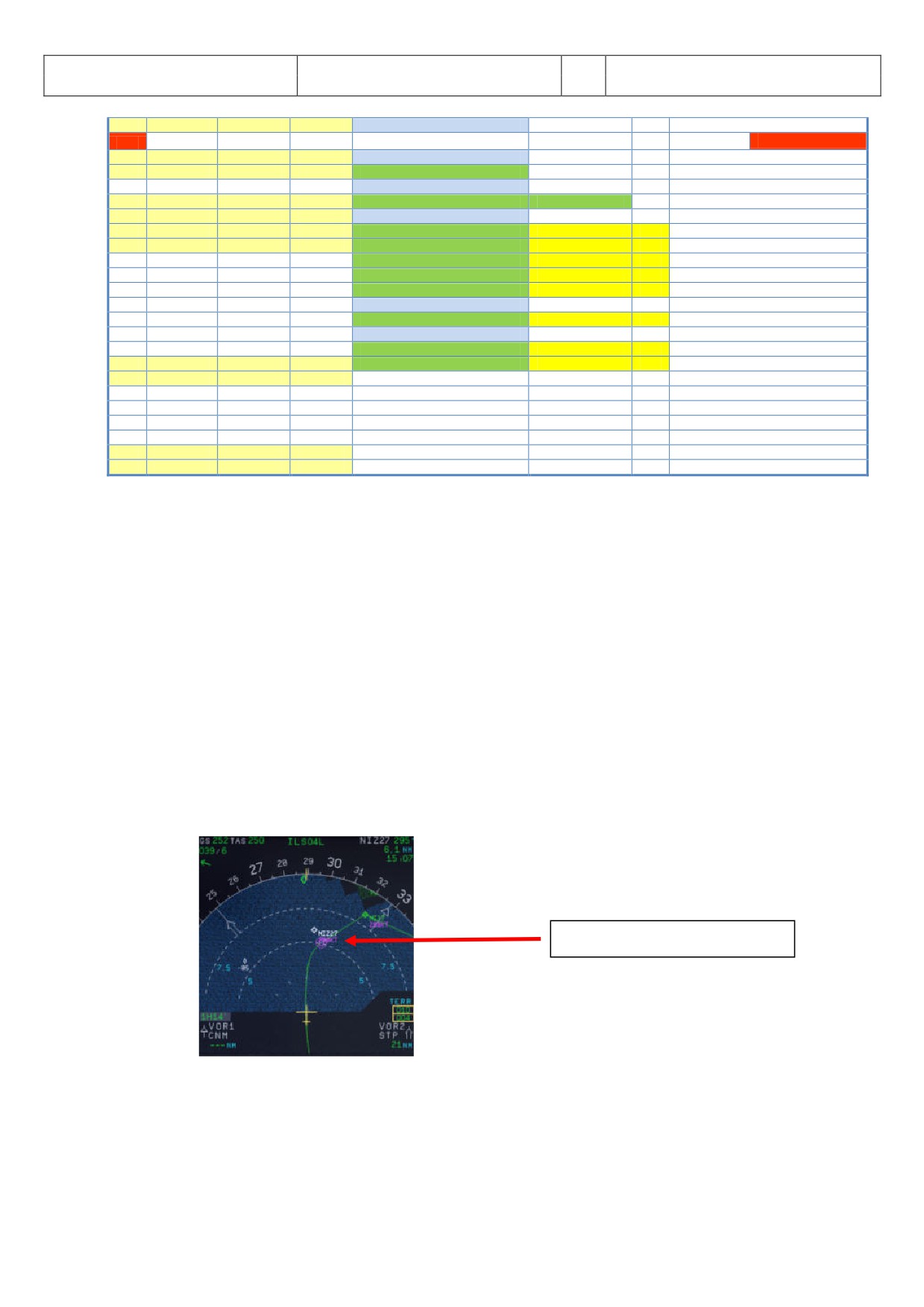
• Automatically at the Deceleration Pseudo Waypoint
(please see picture below) if the
APPROACH CL has been finished; the flight level is below 7.200 feet radar altitude, the RNAV
mode is active and the distance to the airport is less than 30 NM. The (DECEL) pseudo waypoint
is calculated by the FMGC to initiate deceleration in order to be stabilized at VAPP at a specified
point on the approach profile, normally at 1000 feet AGL.
Deceleration Pseudo Waypoint
Picture 70: Deceleration Point
248.
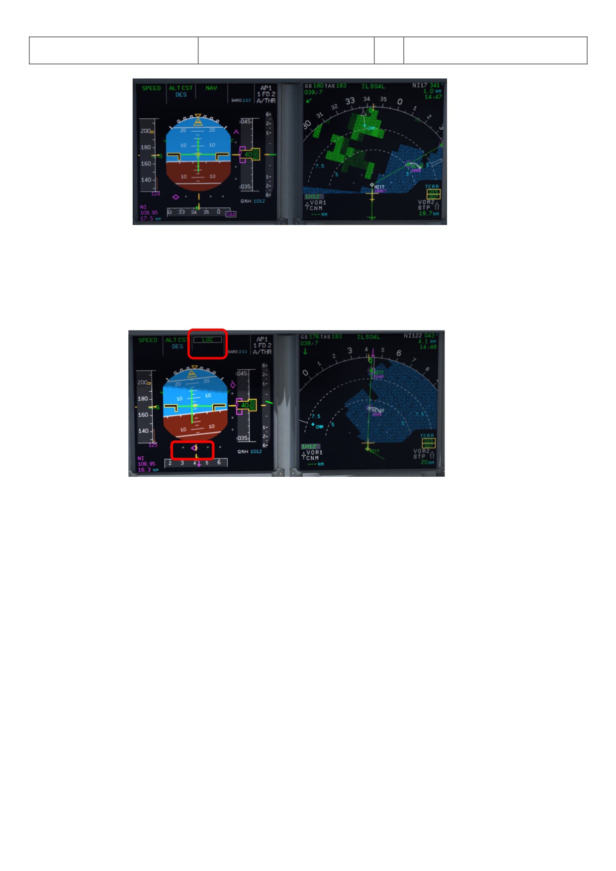
• LOC Alive: Before NI17 the localizer becomes “alive” and this will be confirmed by a PM call
“LOCALIZER ALIVE”. The conditions for this call are: The angle to the runway must be smaller
than 90 ° and the Approach, Landing as well as BaroCheck are not active.
Aerosoft
The Airbus A318/319/320/321 in FSX
Vol
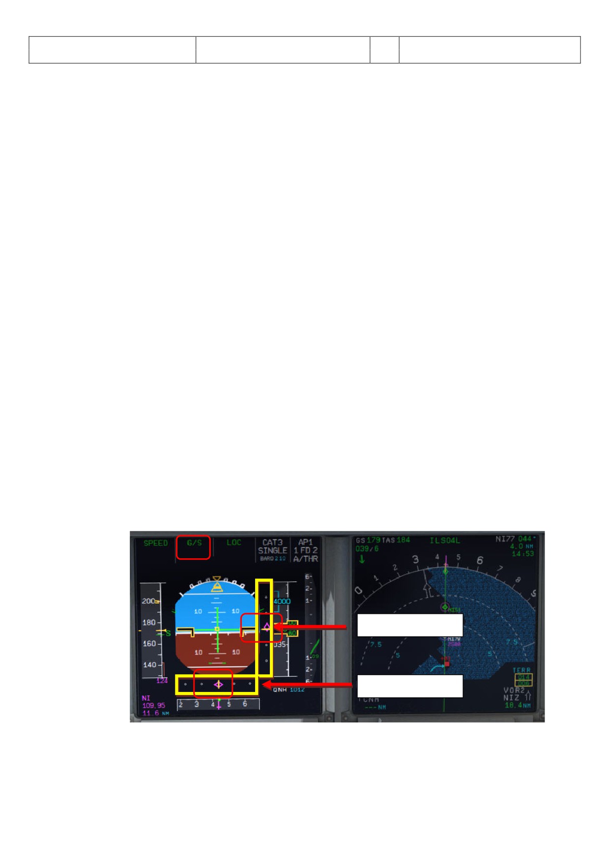
06-01-09 Page 64
Airbus A318/319/320/321
Step-By-Step Tutorial
6
25 October 2015
Picture 71: LOC initiated near NI17
249.
APPR Button: Before passing NI17 (you are already flying at NI122) and after hearing the call
“LOCALIZER ALIVE” = press the APPR button on the FCU.
250.
LOC Capture: The “capture” will be confirmed i.e. lateral path has been caught. Please note: If you
are pushing the APPR button too early (before turning to NI17/NI122) it might happen that the
plane captures the localizer in the wrong direction. Please see also chapter 6.4 for details. First the
lateral path will be caught (LOC* or LOC displayed on the PFD -FMA)
Picture 72: LOC captured
251.
Green Dot Speed / CLEAN: After initiating the APPR Phase (#242) automatically the MCDU reduces
the speed to “Green Dot Speed” (195 knots). But if the plane is already on the glidescope it is not
going to change its pitch to reduce to “Green Dot Speed”.
252.
Flaps: During the approach the flaps will be slowly step by step extended from 1 (after reaching
“Green Dot Speed”) to FULL based on aircraft speed - The flaps will be extended to 1 at least
automatically 10 NM before the runway threshold if IAS is below VFE.
253.
S Speed: After the flaps are deployed by the Copilot to 1 the MCDU automatically reduces the speed
to S-Speed (172 knots). If the plane does not slow down to S-Speed then just use the speed brakes
until S-Speed is reached.
Some general information on the use of speed brakes:
Normally you can use them whenever wanted. But there are some SOP things which have to be
considered. The first one has to do with high altitude flying (FL300 and higher). You cannot yank
them to their full position at once. You have to be smooth as to not disrupt the airflow to sudden.
When on auto pilot the speed brake will not even fully open even if you put the lever at full. The
Airbus is limiting the deployment a bit.
The second thing is that you may not use the speed brakes with flaps three or full. This will cause a
roll moment that could impair controllability. Some models even have an autoretract when having
the speed brakes out at Flaps three/full.
The whole point of the speed brakes is to slowdown the aircraft or to make it descent faster. If the
autothrust is on and in SPEED mode it could be that the engine needs more thrust than idle to keep
the managed/selected speed and this will give a warning. Having the speed brakes out and throttling
Aerosoft
The Airbus A318/319/320/321 in FSX
Vol
06-01-09 Page 65
Airbus A318/319/320/321
Step-By-Step Tutorial
6
25 October 2015
up is a no-no. It just does not make sense.
254.
FLAPS 2 (OPTIONAL): Another method to reduce to S-Speed is to manually deploy the flaps to 2
already just after setting the flaps to 1 but keep in mind the VFE limits. This method is also
supported by the Checklist- and Copilot-Function.
255.
Glideslope “alive”: When the Localizer has been captured (please see picture #70 above) soon after
the vertical glide slope becomes “alive” (magenta rhombus fully appears) which will be confirmed by
a call.
256.
Autopilot:
-
Only with an ILS approach programmed in the FMGC, the approach phase activated and the
APPR button pushed on the FCU you do have the possibility to select both AP’s at the same
time. This will show as AP 1+2 in the PFD FMA.
-
It is normal Airbus procedure to also select the second AP during an ILS approach. It does not
matter if this approach is a CAT 1, 2 or 3. The main reason for this is that if one AP goes offline
the other can take over. This is a principle that is called fail operational. Meaning that when one
AP disconnects for whatever reason the second one will take over immediately - without any
interference/action by the pilot. But in reality only one AP is doing the flying and the other one
is just standing by to take over if needed. To have both AP’s active is a requirement for CAT 3
approaches but it gives an added safety with CAT 1 and 2. So why not selected both during all
ILS approaches Airbus must have thought.
-
Autoland goes hand in hand with CAT 2 and 3 approaches but as a system it is separate.
Autoland is technically possible with 1 AP but certification of the airline, airport, and airplane
must all be met.
-
An ILS CAT 1 may be landed manual at all times. A CAT 2 may be landed manual but this is also
up to certification rules for the airline, airport and airplane - but normally an autoland is the
norm here. A CAT 3 must be made with an auto land system.
-
If autoland is used it means that there is no manual flight path interference of the pilots until
after touchdown and the aircraft is landing fully automatic.
-
In our case because LFMN ILS 04L allows only CAT 1 landings we will use both autopilots but will
make no “autoland”.
Additional information on the various CAT you will also find in #211.
258.
Glideslope “captured”: When the glideslope has been captured it will be confirmed by a call. After
the vertical glide path has been caught the display on the PFD-FMA looks as follows (please see
picture 71 below):
Vertical glide path
Lateral path
Picture 73: PFD - Glidescope captured - Vertical and lateral glide path
The middle of both fields shows the vertical and lateral position of the aircraft where as the
magenta rhombus shows the actual position on the glide path. This means that during the approach
Aerosoft
The Airbus A318/319/320/321 in FSX
Vol
06-01-09 Page 66
Airbus A318/319/320/321
Step-By-Step Tutorial
6
25 October 2015
both rhombuses are moving to the center. The picture above shows a position at which the aircraft
is on the nearly ideal position for landing.
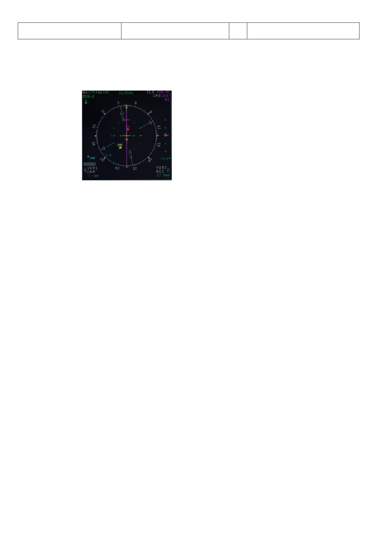
On the EFIS control panel please change the knob for the various views to LS. This view also shows
the glide path and the position of the aircraft to it.
Picture 74: ND - ILS view LFMN Rwy 04L
259.
Landing Memo: The conditions for the Landing Memo are:
•
< 2000 feet RA above runway altitude
•
Flight mode: Cruise or Approach
•
Both thrust levers at or below CL detent
The “LANDING” checklist is “interrupted” until the “Landing Memo” becomes available in the Upper
ECAM. The Copilot then continues with the settings i. e. flaps 2, gear down etc.
259a.
Speed Restriction 160 knots: On certain airports like p. e. EGLL speed restrictions apply like 160 kts
before till 4 NM before the runway. This is a bit difficult because on the other hand SOP states the
plane has to be fully established at 1000 feet RA. So Flaps 2, speed brakes and sometimes even gear
down is used to keep the 160 knots. If the Checklist, the Copilot and SPD SEL = 160 knots is used the
gear will not automatically be deployed at <2000 feet RA as well as the flaps not set to 3 and full -
only after SPD SEL is <160 knots or in MNGD mode.
260.
Flaps 2: At calculated speed (but must be lower than VFE = 200 knots) the flaps are automatically
extended to 2 by the copilot (if = ON). If the calculated flaps 2 extension speed is higher than VFE
the plane must be near MLW or even above. This means it is an emergency situation. In such a case
do not use “Managed Speed”, but set the speed manually to a value below VFE = 200 knots (e.g. 195
knots). The flaps then will be automatically extended by the copilot (if = ON). After the flaps have
been extended to 2 you can again use “Managed Speed” for landing.
261.
GoAround ALT: This is the altitude a plane has to fly to when using the GO AROUND procedure
(MCDU FPLAN waypoints in blue) in case a landing has to be aborted. Set the GoAround Altitude
according to the FPLAN e.g. change the set altitude on the FCU to the first altitude to be reached
after a “Go Around”. Please just change the altitude and do not press or pull the knob at this point.
In case the Copilot function is enabled it is automatically set by the copilot under following
conditions:
• FAF passed - plus 0.5 NM added
• Actual flight level below GA ALT
• Actual flight level below FCU set ALT
• Vertical speed below 250 knots
If the copilot function is set to ON the highest value is automatically inserted using the MCDU FPLAN
data. The value will be entered by the copilot in visible steps (with sound) and also considering the
100 and 1000 switch. Some values like 3.490 feet cannot be entered so the next possible higher
value which means for 3.490 = 3.500 has to be or are entered.
If no values are available in the F-PLAN or there is no GA flight path available in the NAV DB the
copilot sets the value to a value of (airport altitude rounded to next full 1.000) plus 4.000 feet e. g.
Aerosoft
The Airbus A318/319/320/321 in FSX
Vol
06-01-09 Page 67
Airbus A318/319/320/321
Step-By-Step Tutorial
6
25 October 2015
normally to 5.000 feet.
269.
Landing Memo / blue entries - : Please check if there are no “blue” entries in the Landing Memo. If
for some reasons there are still “blue” entries (you might have forgotten to make certain settings)
then please make those settings now.
270.
Set VAPP: After the flaps are set to FULL and the landing gear is down the speed now should be
changed to Vapp speed in our example to 126 as calculated by the FMGC - MCDU (PERF APP). As we
are flying in “Managed Mode” the speed automatically is reduced to Vapp after the flaps are set to
FULL - i.e. nothing has to be done as we are using the “Managed Mode”.
It is the final approach speed and automatically be calculated / inserted by the system. It is
calculated in the following way: VLS plus 1/3 of the tower headwind component. The value of VAPP
is limited so that it is never less than VLS + 5 or more than VLS +15. As a result, VAPP is increased
above its minimum value for runway headwinds above 15 knots. VAPP correction is not increased
further for headwinds exceeding 45 knots. No additions are made for gusts.
275.
Auto Throttle: Leave the A/THR on…..
276.
Wing Anti Ice: Leave the Wing Anti Ice OFF
There are also various other approach procedures used depending on airline and weather condition (ILS- and
non-ILS-approaches).
5.22
Landing
LANDING
PANEL
ACTION
NO.
REMARK
TYP
PART (Name)
PART (No.)
PF (PILOT FLYING)
PM (PILOT MONITORING)
277
Flaps in Landing Config. (MCDU Settings)
Start next Checklist / Co-Pilot - if selected
278
MAIN PANEL
GEAR
7
LAND. GEAR = FULL EXTRACTED
CHECK
CoP
279
PEDESTAL
SP. BRAKEs
6
GROUND SPOILERS = ARMED
CHECK
CoP
FSX: Right mouse click
280
MAIN PANEL
AUTO BRAKE
6
AUTO BRAKES = MEDIUM
SET
CoP
281
OVERHEAD
EXT. LIGHTS
9
NOSE = TO or TAXI / LANDING L. = ON
CHECK
CoP
282
FCU
ALT
3
GO AROUND ALT
CHECK
CoP
283
AT DECISION ALTITUDE
284
FCU
AP
5
AP
OFF
CoP
FSX: Z
285
At 20 feet:
286
FLARE
PERFORM
287
MAIN PANEL
PDF
1
ALTITUDE
MONITOR
288
PEDESTAL
THR LEVER
4
THRUST LEVERS
IDLE
FSX: F1
289
At touchdown:
290
PEDESTAL
THR LEVER
4
REV
MAX
FSX: F2
291
BRAKES
AS REQUIRED
292
At 70 knots:
293
PEDESTAL
THR LEVER
4
REV
IDLE
FSX: F1
294
At taxi speed:
295
PEDESTAL
THR LEVER
4
REV
STOW
CoP
296
Before 30 knots:
297
MAIN PANEL
AUTO BRAKE
6
AUTOBRK
DISENGAGE
CoP
Checklist complete
298
FCU
AP
5
AP (if applicable)
OFF
CoP
FSX: Z
280. Auto Brake: Set to MED (medium)
281. Exterior Lights: Just check if all Exterior Lights are on: Strobe, Beacon, Nav & Logo as well as Landing
Lights.
282. Go Around Altitude: Check if the GA has been set correctly according to #262.
283. BARO - DA (decision altitude): Please also see #211 - for LFMN ILS 04L according to the charts = 210
feet. At an altitude of 310 feet there will be a call “100 ABOVE”.
284. Autopilot: Because LFMN ILS 04L is ILS CAT1 we are not allowed to use “AUTOLAND” and have to
disconnect the autopilot at latest at the decision altitude of 210 feet. Some airlines require that if no
AP is used also the ATHR has to be switched off.
286. LAND and FLARE mode: As the aircraft gets closer to the ground the LAND mode engages, then the
FLARE mode. The actual modes are shown on the FMA.
288. Thrust Levers: IDLE: There is a callout: RETARD. A single callout if thrust levers are retarded in time,
Aerosoft
The Airbus A318/319/320/321 in FSX
Vol
06-01-09 Page 68
Airbus A318/319/320/321
Step-By-Step Tutorial
6
25 October 2015
multiple callouts if not (auto landing = callout at 10 ft, manual landing = at 20 ft).Pull the trust levers
back to IDLE and let the aircraft gently touch the ground.
290. Trust Levers: REV: After touchdown the thrust reversers (by using F2 from the keyboard) might be
activated but not necessarily if noise abatement procedures prohibits it.
291. BRAKES: The autobrake makes the aircraft decelerate on the ground. You can also take the control at
any time by using the brakes. Any manual action on the brakes automatically disconnects the
autobrake system.
295. REV THRUST: If REV THRUST is used (#284 and #287) the levers are automatically stowed by the
Copilot.
298. AUTOPILOT: We switched the autopilot OFF because at LFMN ILS04L = ILS CAT1 we are not allowed to
make an “AUTOLAND”. But for ILS CAT2 and 3 landing (if the AP is ON) shortly after landing e. g. the
plane is still on the centerline the autopilot is automatically switched off and the warning signal goes
on. The signal will automatically be switched off by the Copilot.
5.23
Go Around
The GO AROUND flight path is displayed on the ND (in blue) if:
• A missed approach waypoint (MAP in blue) is displayed on the MCDU F-PLAN page (in line 2, 3, 4 and/or
5), while ND is in ROSE or ARC mode or
• Displayed on the MCDU F-PLAN page in line 2, while ND is in PLAN mode.
The GO AROUND procedure is as described below:
• After initialization of the GA „GO AROUND ACTIVE“ is displayed on the INFOBAR.
• After reaching GA ALT and the AFTER TO CHECKLIST has been finished "CLIMB OR CONTINUE FOR NEW
APPROACH“ is displayed on the INFOBAR.
• If additionally to the GA ALT a higher altitude is selected:
o Up to 10.000 ft: Nothing has to be done and there is no INFOBAR display.
o Higher than 10.000 ft: The checklist function changes into CLIMB- and after that as usual into
CRUISE-, and DESCENT PREP-mode (initialization maybe without delay because no T/D is
available). The remaining procedure is according to a normal approach.
• Generally the Approach CL will be initialized after a GA 30 NM and automatically started 25 NM before
the destination airport. A message is displayed on the INFOBAR: APPR. CL STARTS IN x MILES OR
MANUALLY START CL …… E. g. it can be manually started using „1“ from the keyboard or from the
MCDU2 menu itself.
• When the APPR. CL has been finished manually start the MCDU PERF APPR. PHASE (also a respective
message appears on the INFOBAR)
GO AROUND
PANEL
ACTION
NO.
REMARK
TYP
PART (Name)
PART (No.)
PF (PILOT FLYING)
PM (PILOT MONITORING)
A
PEDESTAL
THR LEVER
4
GA thrust is set
SET
Start Checklist / Co-Pilot - if selected
B
PEDESTAL
FLAPS
8
“GO AROUND FLAPS”
FLAPS ONE STEP BACK = 3
CoP
FSX: F6
C
“Positive climb”
Radio Alt >50 ft, VS > 100 ft/min
D
MAIN PANEL
GEAR
7
“Gear up”
GEAR UP
CoP
FSX: G
E
MAIN PANEL
GEAR
7
GEAR STOWED
“Gear up , Flaps 3”
F
PEDESTAL
SPEED-BR.
6
GROUND SPOILERS
DISARM
CoP
FSX: /
G
OVERHEAD
EXT. LIGHTS
9
RUNWAY / NOSE = OFF
„Off“
CoP
H
MAIN PANEL
BRAKES
6
AUTOBRAKES
„Off“
CoP
I
At Thrust Red. / Acceleration Alt.
J
PEDESTAL
FLAPS
8
“Flaps 1”
SELECT
CoP
FSX: F6
K
PEDESTAL
THR LEVER
4
SET LEVERS TO
"CLIMB THRUST"
Blinking announcement in FMA
L
FCU
AP
5
AUTIOPILOT
ON
M
At “Green Dot Speed” / “S-Speed”
N
PEDESTAL
FLAPS
8
“Flaps up”
SELECT
CoP
FSX: F6
O
“Flaps up”
Checklist complete
P
FCU
AP
5
AUTOPILOT 2
„Off“
CoP
Aerosoft
The Airbus A318/319/320/321 in FSX
Vol
06-01-09 Page 69
Airbus A318/319/320/321
Step-By-Step Tutorial
6
25 October 2015
A.
Thrust Levers: TOGA: If there is an emergency situation and “Go-around” should be performed e.g.
the runway is blocked by another aircraft or if there is a problem with the aircraft itself just set the
thrust levers to the most forward position = MAN TOGA and this GO AROUND procedure- and
checklist will start automatically. Please fly using the procedure and checklist as in the table above.
B.
“Go Around Flaps”: After this PF call the copilot automatically sets the flaps one position back e. g. in
our case as we used FULL: From FULL to 3.
I.
Thrust Reduction Altitude: When the THR RED altitude is reached (1.512 feet in our example) a
flashing LVR CLB message appears on the FMA (1st column).
J.
Flaps: The copilot sets the flaps back to 1. In our case from 3 to 1.
K.
Thrust Levers: Move the thrust levers back to the CL detent = THR CLB (FMA displays SPEED because
the speed is limited to 200 kts). As the thrust reduces when the levers are moved back to the CL
detent, you should anticipate the pitch reduction caused by this thrust reduction. Take a 10° pitch
angle.
L.
Autopilot: Because for an ILS CAT 1 landing at LFMN LIS04L we switched the autopilot OFF now the
autopilot has be engaged again. If in connection with other landings the autopilot is still set to ON
then the PF just confirms the setting.
M. Green Dot / S-Speed: At “Green Dot / S-Speed the PF calls “Flaps up”
O.
Flaps UP: The copilot sets the flaps to UP.
P.
2nd Autopilot: Automatically set to OFF after the Thrust Reduction Altitude has been reached (if
applicable).
Setting the Thrust Levers to MAN TOGA the GA flight path on the ND changes to “green” (in the MCDU too) and
becomes active. The plane will climb to 2.000 feet which is the GA altitude for the last GA waypoint = NERAS
and automatically follow the GA flight path (for LFMN ILS04L those are the waypoints 320, INTCPT and NERAS).
Also automatically the flight path for another approach (including GA) at the same runway is entered into the
MCDU on the FPLAN pages. This another approach flight plan is divided from the active flight plan by a F-PLAN
DISCONTINUITY and only consists of the final waypoints for ILS04L and does not include any TRANS or VIA
waypoints.
As ATC advises us to fly a holding at NERAS at an altitude of 4.000 feet we have to climb from 2.000 (set GA
ALT) to 4.000 feet. So change the altitude on FCU ALT to 4000 and push the knob. Then the plane will climb to
FL40.
Descent or Climb-to-Altitude On the Infobar you will see the following message: CHANGE FCU ALT FOR NEW
APPROACH OR START APPROACH CL (MCDU OR KEY 1).
Picture 75: ND - G/A flight path for LFMN ILS04L
Before reaching NERAS we will enter a holding into the F-PLAN to wait for further instructions from ATC.
• MCDU FPLAN: Scroll to NERAS (should be at the beginning e. g. before the FPLAN DISCONTINUITY) and
push the respective LSK L.
• HOLD: Push LSK 3L
Aerosoft
The Airbus A318/319/320/321 in FSX
Vol
06-01-09 Page 70
Airbus A318/319/320/321
Step-By-Step Tutorial
6
25 October 2015
• INBOUND COURSE: Enter 298 according to the aeronautical charts (LSK 1L)
• DISTANCE: Enter “/5.0” as distance of the holding (LSK 3L)
Picture 76: MCDU - F-PLAN - Entering a holding at NERAS
• TEMPORARY F-PLAN: Push LSK 6L
• TEMPORARY INSERT: Insert the TEMPORARY F-PLAN - Push LSK 6R
A “HOLD R” is entered into the FPLAN after NERAS (please see picture below).
Picture 77: After entering a holding at NERAS
Now there are two options to continue the flight:
A. Another attempt to land at LFMN ILS04L
• Only the FINAL waypoints for LFMN ILS04L (NI77 and NI51) have automatically been added to the
FPLAN.
• But we are advised to use TRANS/VIA “NERAS” again for our approach. So please push LSK6L,
then ARRIVAL LSK1R and using LSK2L (VIA) select NERAS. Between F-PLAN DISCONTINUITY and
NI77 now the waypoint for the NERAS approach are inserted.
Aerosoft
The Airbus A318/319/320/321 in FSX
Vol
06-01-09 Page 71
Airbus A318/319/320/321
Step-By-Step Tutorial
6
25 October 2015
Picture 78: After entering VIA NERAS for new approach
• Delete = CLR the FPLAN-DISCONTINUITY between HOLD R and NERAS (first waypoint for another
approach at LFMN ILS04L).
Picture 79: After deleting F-PLAN DISCONTINUITY
• If the F-PLAN DISCONTINUITY is not cleared and NERAS (last waypoint of the GA flight path) is reached
or HOLD R is left, the FMGS will go into PPOS Mode, where it will revert to Basic AP Modes (HDG and
VS/ALT/ALT*).
• EXIT HOLD R: Push the respective LSK R on the F-PLAN page to exit the holding
Picture 80: After EXIT the holding
• Fly another approach.
As in the “real” Airbus there are no ALT/SPD PREDICTIONS available in GA phase. Also, there is no DECEL
point calculated and symbol displayed on the ND during GA phase. The APPR PHASE (MCDU - PERF - APPR)
has to be manually activated as well as previously the APPROACH CL (MCDU or Key 1). In our case start
both after leaving the holding on the way to AZR26.
Aerosoft
The Airbus A318/319/320/321 in FSX
Vol
06-01-09 Page 72
Airbus A318/319/320/321
Step-By-Step Tutorial
6
25 October 2015
Picture 81: ND - After activating flight path for another attempt
If there is no ALT change to your next waypoint please start the APPR CL manually (MCDU 2 or from the
keyboard using “1”). As in our case there is no ALT change between NERAS and AZR26 (= 4.000 feet) so
after leaving HOLD R start the APPR CL manually.
B. Diversion to another Airport
Please see chapter 7.2 - Alternate Destinations - for details.
5.24
After Landing
AFTER LANDING
PANEL
ACTION
NO.
REMARK
TYP
PART (Name)
PART (No.)
PF (PILOT FLYING)
PM (PILOT MONITORING)
299
Ground Speed >35 / Dir. to runway > 15 °
Start Checklist / Co-Pilot - if selected
300
GLARESHIELD
CHRONO
7
CHRONO
STOP
Push upper right button
301
OVERHEAD
EXT. LIGHTS
9
NOSE LIGHTS
ON
CoP
302
OVERHEAD
EXT. LIGHTS
9
LANDING LIGHTS
OFF
CoP
303
OVERHEAD
EXT. LIGHTS
9
STROBE LIGHT = OFF or AUTO
If ON = OFF
CoP
304
PEDESTAL
TCAS
10
TCAS MODE SEL
STBY
CoP
305
PEDESTAL
FLAPS
8
FLAPS
RETRACT
CoP
FSX: F6
306
PEDESTAL
ENGINE
5
ENG MODE SEL
NORM
Cop
307
PEDESTAL
WXR
11
WXR: SET system to OFF
SET
Cop
308
EFIS
FD / ILS
3
ILS LOCALIZER (LS)
OFF
CoP
EFIS
309
OVERHEAD
APU
10
APU MASTER and APU START
ON
310
PEDESTAL
SP.BRAKES
6
GRND SPLRS
DISARM
CoP
FSX: /
311
ECAM
WHEEL PAGE
1
BRAKE TEMP all wheels = > 300 degrees
CHECK
Checklist complete
301. Exterior Lights: Set “NOSE” light to „ON“.
309. APU START: Becomes available 10 seconds after starting APU MASTER
AES
Open the AES (CTRL+SHIFT+W) or GSX (CRTL + F12) window. In AES / GSX select the option “F2 -
GSX: Increment Position” until you see the gate position: A14 and then select “F3 - Request Follow-Me to
selected Position”. Follow the car. When you are at the gate and have set the parking brakes to ON
you will hear “Blocks in position” i.e. you have reached the right position.
5.25
Parking
PARKING
PANEL
ACTION
NO.
REMARK
TYP
PART (Name)
PART (No.)
PF (PILOT FLYING)
PM (PILOT MONITORING)
312
PEDESTAL
RADIO
1
ATC (if no AUTO position)
STBY / OFF
313
OVERHEAD
ANTI-ICE
8
ANTI ICE (WING and ENGINES 1&2)
CHECK = OFF
314
PEDESTAL
RADIO
1
GROUND CONTACT
ESTABLISH
If ATC is used
315
PEDESTAL
P.BRAKE
7
PARKING BRAKE ON
SET ON
FSX: CTRL + . (period)
316
PEDESTAL
ENGINE
5
ENG MASTER 1 & 2
OFF
Start Checklist / Co-Pilot - if selected
317
MCDU R
GRND SERV
CHOCKS
SET
CoP
318
PEDESTAL
P.BRAKE
7
PARKING BRAKE
OFF
CoP
FSX: . (period)
319
OVERHEAD
SIGNS
11
SEAT BELTS
OFF
CoP
320
OVERHEAD
EXT. LIGHTS
9
BEACON LIGHT
OFF
CoP
321
OVERHEAD
EXT. LIGHTS
9
TAXI LIGHT.
OFF
CoP
Aerosoft
The Airbus A318/319/320/321 in FSX
Vol
06-01-09 Page 73
Airbus A318/319/320/321
Step-By-Step Tutorial
6
25 October 2015
322
OVERHEAD
ANTI-ICE
8
WING & ENGINE ANTI ICE = OFF
CHECK
Cop
323
OVERHEAD
FUEL
2
FUEL PUMPS
OFF
CoP
OFF should appear / Checklist complete
324
MCDU R
GRND SERV
CONES
SET
325
MCDU R
GRND SERV
ESTABLISH EXTERNAL POWER
CONNECT
326
OVERHEAD
EXT POWER
6
EXT. POWER = AVAILABLE
SET TO ON
327
OVERHEAD
APU
10
APU MASTER
SET TO OFF
328
MCDU
MENU
ACFT DOORS
DOORS
OPEN (AS REQUIRED)
318. CHOCKS / PARKING BRAKE: Because the brakes have to cool off after landing, the parking brake can
be released after the chocks have been set. The plane is then just held by the chocks only.
325. EXT POWER: Depending on the situation at the airport direct external power or delivered by a GPU is
used to deliver the power needed. Please select the equivalent. For Vienna we just use EXTERNAL
POWER (no GPU).
327. APU: After the connection to external power is established the APU can be set to OFF.
AES
Open the AES (CTRL+SHIFT+W) or GSX window (CRTL + F12) and select your options.
GSX:
5 Minutes after the “Parking CL” has been finished the complete system (incl. MCDU) is automatically reset
and you are able to prepare for a “turnaround” e. g. starting again with the “Cockpit Preparation CL”. A
specific information is available in the infobar.
5.26
Securing Aircraft
SECURING AIRCRAFT
PANEL
ACTION
NO.
REMARK
TYP
PART (Name)
PART (No.)
PF (PILOT FLYING)
PM (PILOT MONITORING)
329
OVERHEAD
ADIRS
ADIRS (1 + 2 + 3)
OFF
330
OVERHEAD
EXT. LIGHTS
9
NAV. LIGHTS
OFF
331
OVERHEAD
SIGNS
11
NO SMOKING & EMERGENCY LIGHT
OFF
332
MCDU
MENU
ACFT DOORS
DOORS
CLOSE (AS REQUIRED)
333
OVERHEAD
EXT. PWR
6
EXT PWR
AS REQUIRED
334
OVERHEAD
ELEC
5
GEN 1 + 2 (Electric Generators)
PRESS
OFF should appear
335
PEDESTAL
INT. LIGHT
3
INTEG LT
OFF
336
MAIN PANEL
PFD LIGHT
8
SWITCH
OFF
337
MAIN PANEL
ND LIGHT
8
SWITCH
OFF
338
ECAM
DIMMER
4
SWITCH UPPER and LOWER
OFF
339
PEDESTAL
RADIO
1
RADIO CONTROL PANEL
OFF
340
PEDESTAL
TCAS
10
TCAS = STBY
SET
341
OVERHEAD
BATTERIES
4
BAT 1 + 2
OFF
330. Exterior Lights: Switch off all exterior lights.
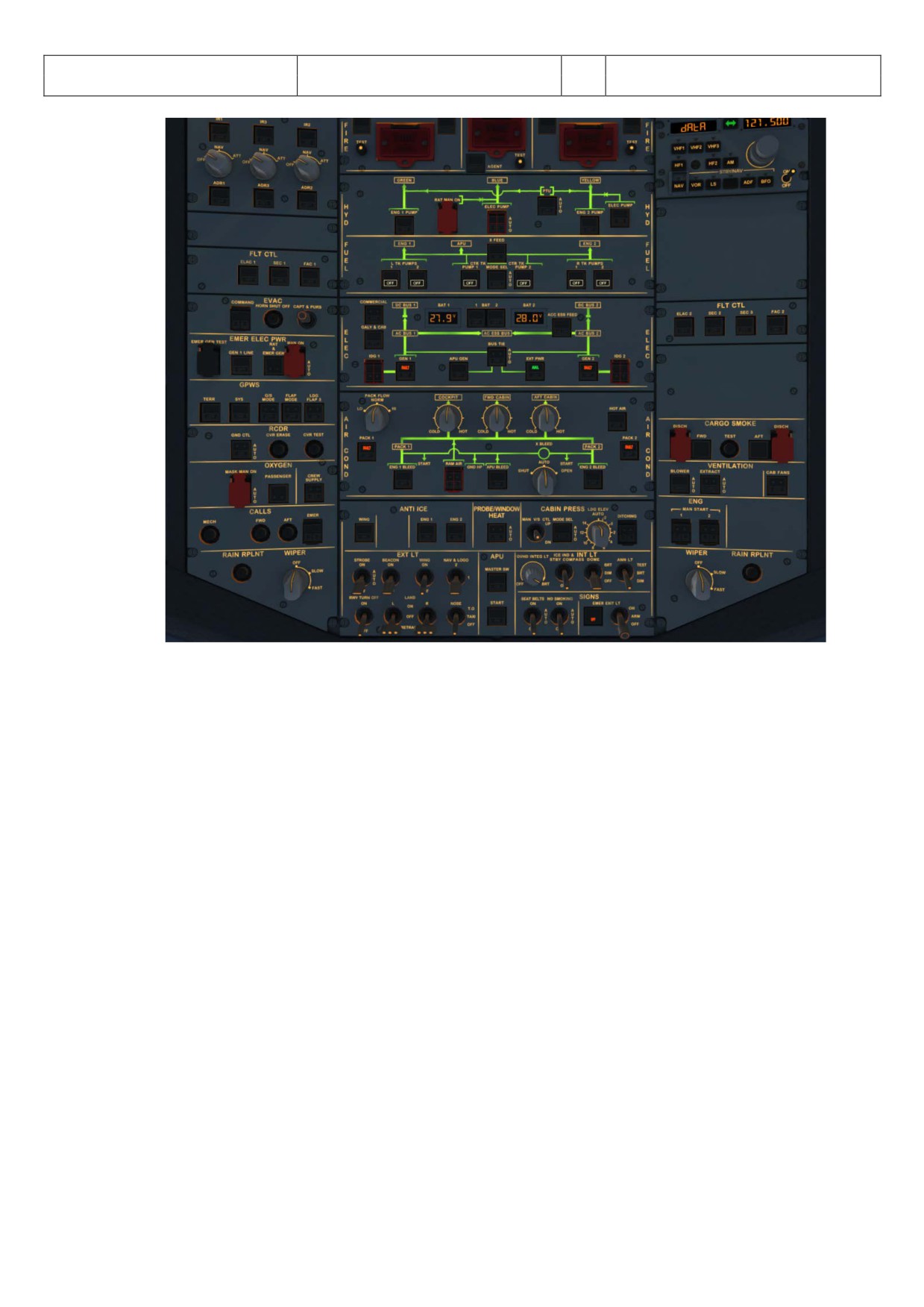
XXX. Cockpit „COLD DARK“: Now the status of the cockpit should be “COLD DARK”. All systems and switches
should be “OFF”. Before switching the batteries to OFF the panel should look like in the following
picture:
Aerosoft
The Airbus A318/319/320/321 in FSX
Vol
06-01-09 Page 74
Airbus A318/319/320/321
Step-By-Step Tutorial
6
25 October 2015
Picture 82: Overhead Panel before switching OFF both batteries
Aerosoft
The Airbus A318/319/320/321 in FSX
Vol
06-01-09 Page 75
Airbus A318/319/320/321
Step-By-Step Tutorial
6
25 October 2015
6. Vector Approach using DIR TO and RADIAL IN
This part of the tutorial uses also the flightplan LOWILFMN01 (Innsbruck to Nice) but covers only the descent from
cruise level and the vector approach into Nice = LFMN 04L. It is mainly based on input from Frank “The Dude” (a RW-
pilot) how a RW vector approach is flown into LFMN ILS 04L.
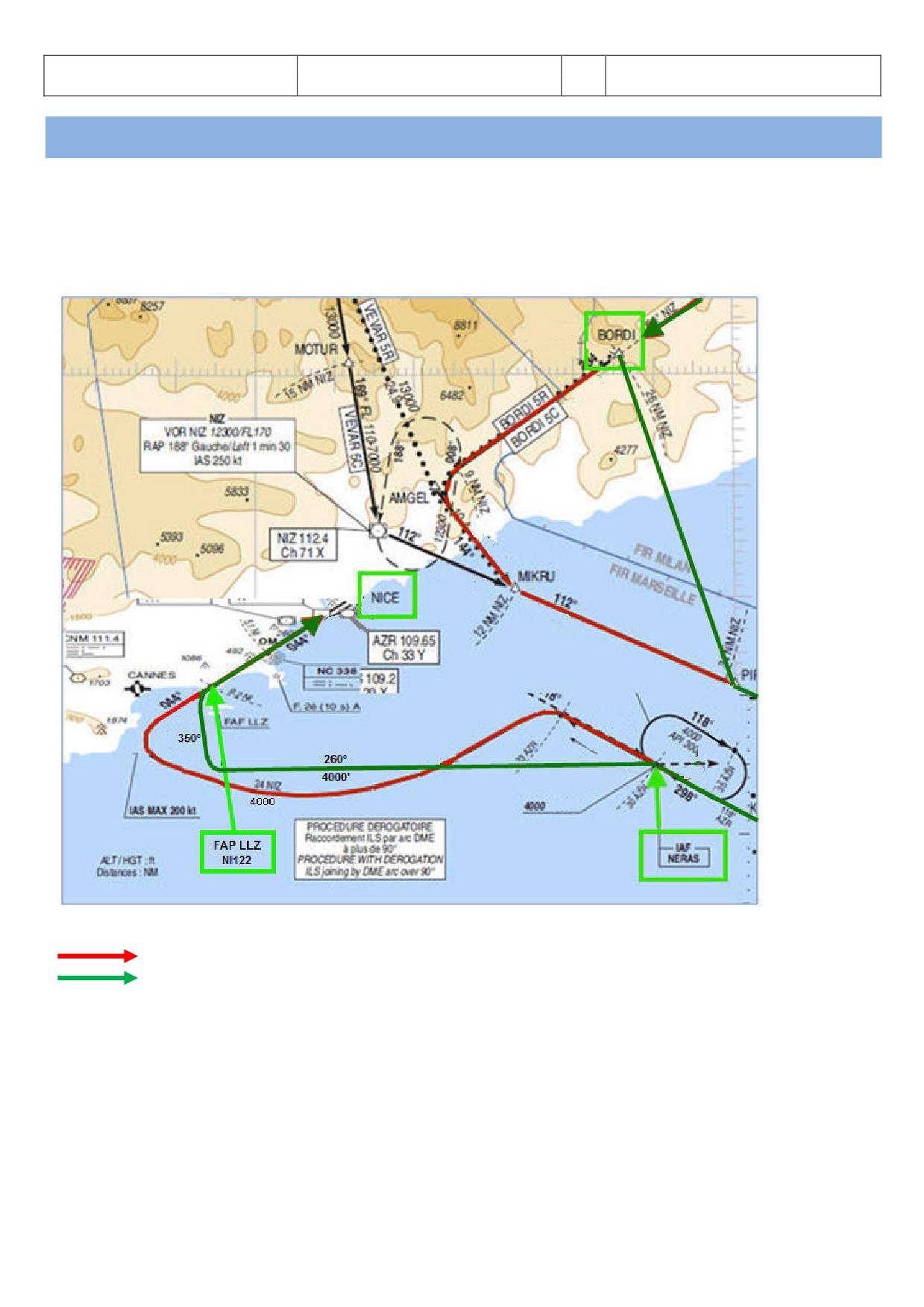
FLIGHTPATH APPROACH LFMN ILS04L
Picture 83: Vector approach flight path into LFMN
MCDU F-PLAN
Actual flight path
ATC only makes us leave our cruising altitude when they have some sort of ATC competence boundary where they
have to hand us over to somebody else. On our flight to Nice that would be BORDI. This is the ATC border between
Italy and France. The French want us in FL170 when entering their airspace. The reason is that Nice outbound planes
going towards Italian airspace. So the Italian ATC would clear us well ahead of BORDI.
After passing EVANO we will receive ATC instructions for descent::
o ATC - AUA319 Cleared FL170 - reach latest at BORDI. Call me leaving
o PM - AUA319 Cleared FL170 - reach latest at BORDI. Will call you when leaving
Aerosoft
The Airbus A318/319/320/321 in FSX
Vol
06-01-09 Page 76
Airbus A318/319/320/321
Step-By-Step Tutorial
6
25 October 2015
Because we are at FL310 this means a descent of 14000’ equivalent to app. 42 NM (1000’ descent every 3
miles at a V/S of -2500). Adding some “reserve” we should therefore start our descent app. 15 NM before
ENOBA.
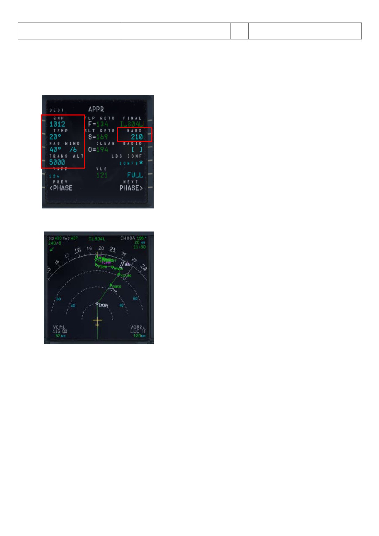
6.1 Prepare the MCDU PERF APPR page
Picture 84: MCDU PERF APPR page
6.2
20 NM before ENOBA manually start the DESCENT PREPARATION CL
Picture 85: Start of DESC PREP CL
6.3 Set the FCU ALT to 17000’.
6.4
15 NM before ENOBA initiate descent to 17000’: Push the V/S knob and set the V/S rate to -2500 (FMA
= VS -2500)
Inform ATC that you are leaving your cruise altitude:
o PM - AUA319 left FL310 - descend FL170 at BORDI
o ATC - AUA319 leaving FL310 descend FL170 at BORDI
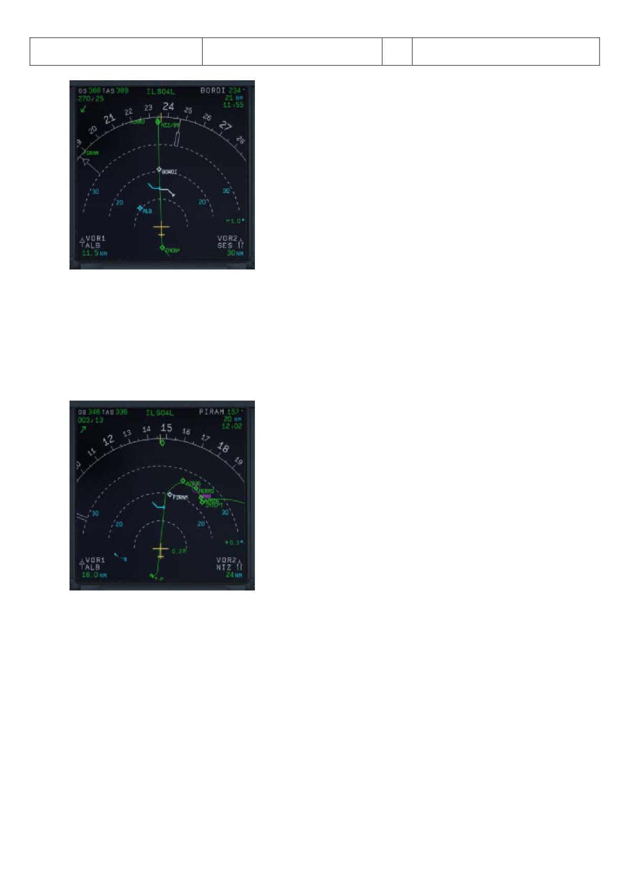
6.5 We will reach FL170 app. 5 NM before BORDI
Aerosoft
The Airbus A318/319/320/321 in FSX
Vol
06-01-09 Page 77
Airbus A318/319/320/321
Step-By-Step Tutorial
6
25 October 2015
Picture 86: Reaching new FL170 before BORDI
Reaching BORDI we get further ATC instructions
o ATC - AUA319 Fly DIR TO PIRAM, descend FL080 - reach latest at PIRAM
o PM - AUA319 DIR TO PIRAM, descend FL080 - reach latest at PIRAM
6.6 Set the FCU ALT to 8000’.
6.7 Initiate descent to 8000’: Push the V/S knob and set the V/S rate to -2000 (FMA =
VS -2000)
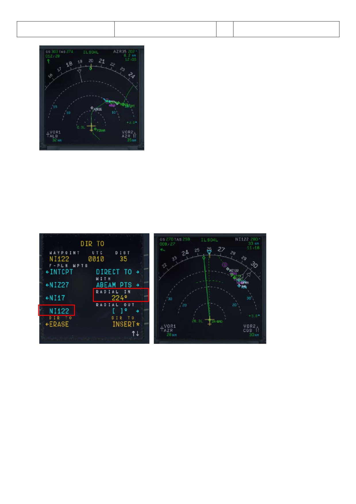
6.8 MCDU / DIR TO select PIRAM and INSERT
Picture 87: ND after entering PIRAM as DIR TO
App. before PIRAM (below 10000 feet)
o PM - Nice approach, AUA319 requesting radar vectors ILS04L
o ATC - Roger AUA319 expect radar vectors
o PM - AUA319, expecting radar vectors
Reaching PIRAM we get further ATC instructions
o ATC - AUA319 - direct NERAS, FL040 reach at NERAS
o PM - AUA319 - direct NERAS, FL040 reach at NERAS
6.9 Enter FL040 into FCU and push the knob (no VS rate necessary because 4000’ is already an ALT CSTR
for NERAS in the F-PLAN (FMA = DES).
Aerosoft
The Airbus A318/319/320/321 in FSX
Vol
06-01-09 Page 78
Airbus A318/319/320/321
Step-By-Step Tutorial
6
25 October 2015
Picture 88: ND after passing PIRAM
6.10 Transition Altitude = 5.000’
At NERAS
o ATC - AUA319 turn right HDG 260 remain FL040, radar vectors ILS runway 04L
o PM - AUA319, turning right HDG 260 FL040
6.11 PF pulls HDG knob on FCU and selects HDG 260
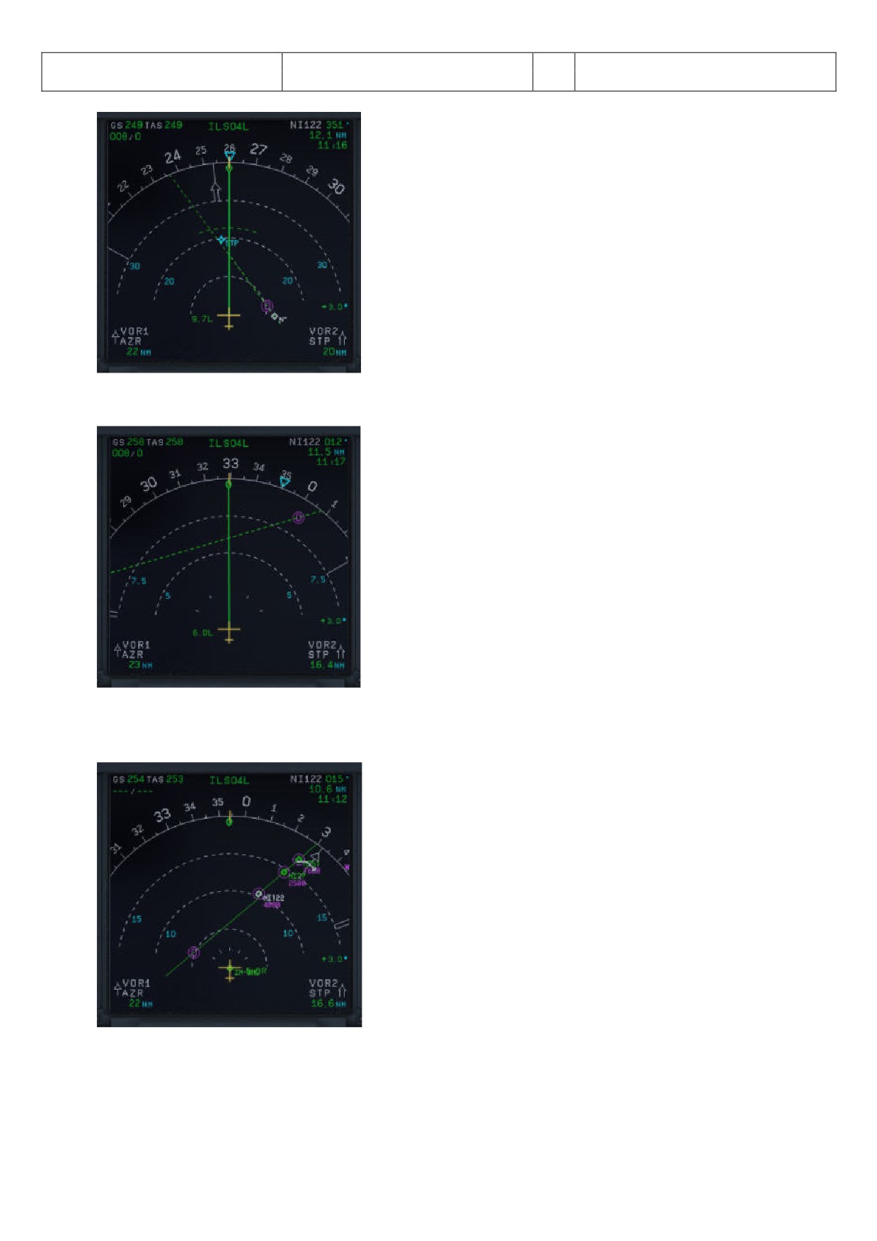
6.12 PF selects MCDU / DIR TO= NI122 (= FAP) and RADIAL IN 224 (044° plus 180°)
Picture 89: Selecting DIR TO and RADIAL IN
Picture 90: ND flight path after DIR TO and RADIAL IN
6.13 PF pulls HDG knob again to disarm the blue NAV mode in the PFD
At app. 18 NM ND distance to VOR 2 STP = St. Tropez
o ATC - AUA319 turn right HDG 350 - intercept localizer - cleared ILS 04L
o PM - AUA319 turning right HDG 350 - intercept localizer -cleared ILS 04L
Aerosoft
The Airbus A318/319/320/321 in FSX
Vol
06-01-09 Page 79
Airbus A318/319/320/321
Step-By-Step Tutorial
6
25 October 2015
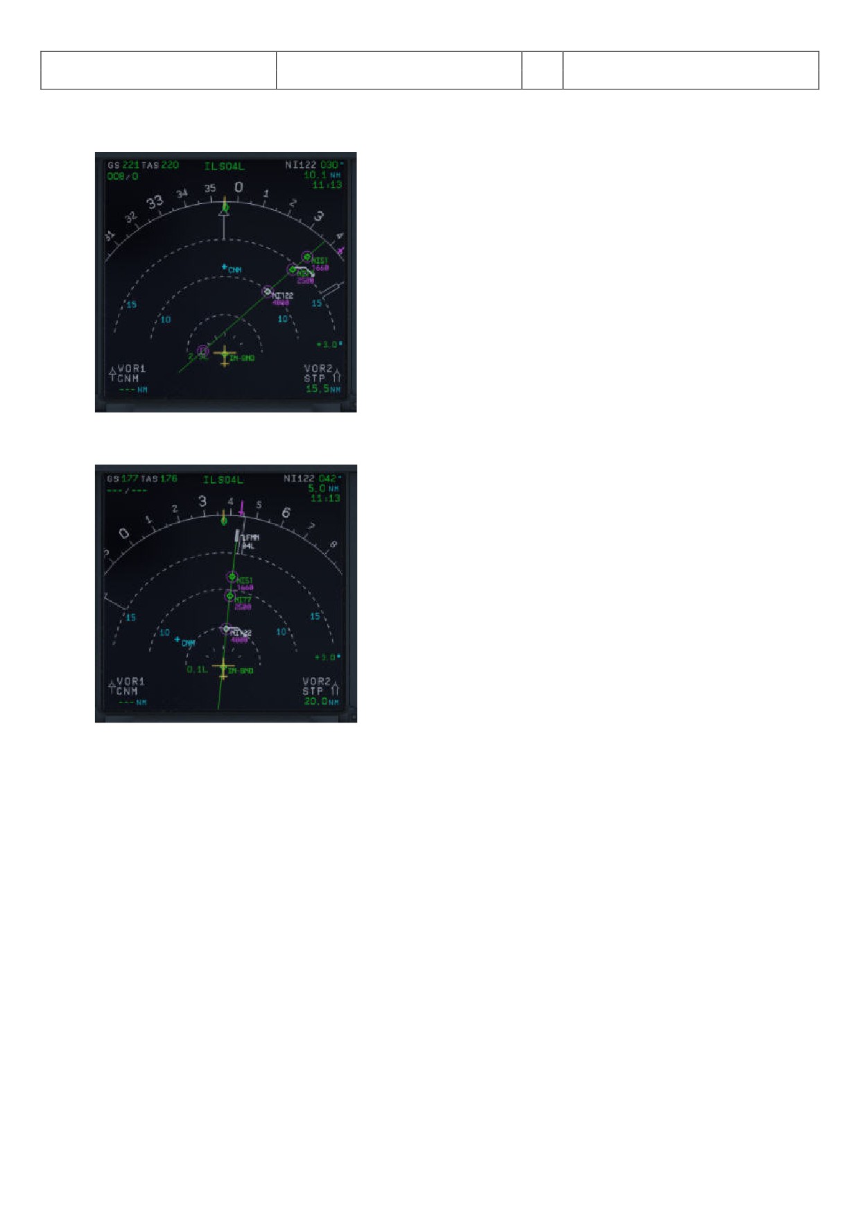
Picture 91: ND flight path before changing HDG 350°
6.14 PF selects HDG 350 on FCU
Picture 92: ND flight path after changing HDG 350°
6.15 Arm the FCU APPR mode by pushing the APPR knob.
6.16 When the approach mode is armed also switch on the second AP.
Picture 93: ND flight path after arming APPR mode
6.17 APPROACH CL starts automatically - after finishing manually activate the MCDU / PERF / APPR PHASE
Aerosoft
The Airbus A318/319/320/321 in FSX
Vol
06-01-09 Page 80
Airbus A318/319/320/321
Step-By-Step Tutorial
6
25 October 2015
6.18 The plane turns into the RADIAL IN course
Picture 94: Approaching RADIAL IN
6.19 When near the RADIAL IN course the final approach flight path becomes active
Picture 95: Final Approach Flight Path
Aerosoft
The Airbus A318/319/320/321 in FSX
Vol
06-01-09 Page 81
Airbus A318/319/320/321
Step-By-Step Tutorial
6
25 October 2015
7.
Non Precision Approach (NPA)
7.1
Introduction
This part is meant to serve as a simple Non-Precision Approach Guide to pilots, unfamiliar with all the tools the
airbus provides for such an approach. This part of the guide is written by Joshua (developer) and a real world
Airbus A 320 pilot. But still there might be some deviations from Real World Procedures.
There are 3 different procedures to fly an NPA with an Airbus, but for all NPAs the „Bird“ is set to ON and used.
SELECTED MODE
• Selected Selected Mode
(Vertical and lateral path are selected in the FCU)
• Selected Managed Mode
(Vertical path is selected and lateral path in the FCU is „managed“)
MANAGED MODE
(Everything is in „managed“ mode e. g. FCU, FMGC and GPS should be „primary“, as well as the „accuracy“ =
set to high)
Additionally it is important, if a Stabilized Approach is flown, like Airbus recommends it for an NPA or if a
Decelerated Approach is used. Both procedures are explained below:
•
Stabilized Approach:
VAPP is set as a „speed constraint“ for the FAF (in our tutorial flight = GAR09)- if this is not happened
automatically - and the plane then is „fully configured” at this point. This means the procedure to
configure the plane for landing starts quite early. Even that Airbus recommends this procedure, most
ATC-Controllers do not accept if the plane flies so early already with app. 140kt. This is the reason why
in reality the Decelerated Approach is the “normal” procedure.
•
Decelerated Approach:
a. Lateral stabilized,
b.
“APPR PHASE” activated - e. g. flying with “green dot” speed - ,
c.
3 NM before FAF (in our tutorial flight = GAR09) = Flaps set to 1,
d.
2000 ft AGL = (in our tutorial flight = MAPT / DMH), flaps set to 2, landing gear = down, spoilers
armed, taxi- and landing lights are switched on,
e. Below VFE = flaps are set to 3,
f. Next below VFE = flaps are set to FULL
g. Landing Checklist
If the Checklist- and Copilot- functions are switched on the necessary settings for points c to g are
automatically made by the PM.
7.1.2
Selected Mode:
As the name describes the PF is responsible to „select“ the right settings on the FCU. As soon as the
plane is “stabilized” (at latest 1nm before FAF = GAR09) the FPA is set to the chosen flight path angle (
-3.4° ) and activated 0.2 - 0.3 NM before FAF.
7.1.3.
Managed Mode:
After receiving the „clearance“ for the approach, push the APPR and the TRK/FPA pushbuttons on the
FCU. The FMA now should display APP NAV and FINAL in cyan = „armed“. Also the V/DEV („brick“)
should appear. But this happens only if the LS pushbutton is not set to ON. In case LS is ON the V/DEV
Aerosoft
The Airbus A318/319/320/321 in FSX
Vol
06-01-09 Page 82
Airbus A318/319/320/321
Step-By-Step Tutorial
6
25 October 2015
should blink in amber.
To change now to the Final APP Mode the following must be given:
• Before the VIP (vertical interception point) the plane must be vertical as well as lateral stabilized (in
our tutorial flight at GAR09).
• The Approach Phase should be activated (happens automatically when passing the „Deceleration
Points“ which is app. 15nm before the landing or has to be activated manually in the FMGC)
• APP NAV must be engaged and FINAL APP “armed” (see FCU)
How to select the „managed“ or „selected“ mode, you know already e. g. to draw or push the required buttons
(drawing = „selected“ and pushing = „managed“).
Of course the PM assists the PF during the approach by calling the distances as well as altitudes so that it is
possible for the PF to check the “glide path”. But this is a brief check of the raw data only. At “Minimum” the
autopilot is switched off (happens automatically - 50 feet below “Minimum”) and the flight is continued
visually. If a landing is not possible under those conditions then a GOAROUND has to be performed.
The following short tutorial for a flight from Vienna to Corfu is an NPA in Managed Mode and using an
Decelerated Approach.
7.2
Settings / Flightplan used for the Tutorial
We are using the A319 for this flight with a ZFW of app. 48.445 kg (80 passengers and 2.000 kg cargo) as well
as a fuel load of 8.575 kg (according to the Load-/Fuel-Planner - in Advanced Mode -).
The flight plan will be as follows:
Departure: LOWW (Vienna/Austria) - Runway: 16 - SID: SASA2B
Flight: SASAL - UZ21 - BABIT - UT23 - TADAM - UM127 - VAL - UN732 - PITAS
Arrival: LGKR (Corfu/Greece) - Runway: 35 = VOR 35-Y - STAR: PITAS2J - TRANS: DIREX
You can manually enter the flight plan or use the existing one LOWWLGKR01. But after loading there is a
F-PLAN DISCONTINUITY between BETAK (end of STAR PITAS2J) and DIREX. Please CLR it.
7.3
Weather LGKR
The expected METAR data for our approach at LGKR are as follows:
Temperature: 25 degrees C
Wind: At 344 degrees at 4 knots
QNH: 1010 HPa
Please adjust the FSX weather settings accordingly.
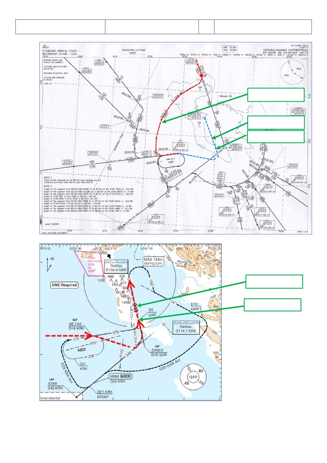
This weather is perfect for using any approach, so we will use VOR35-Y and STAR PITA2J (marked in red on the
charts you will find in 6.5) and TRANS DIREX (marked in blue).
7.4
Checklist- and Copilot Function
We suggest using the Checklist as well as Copilot Function for this flight because then you are fully able to
concentrate on this NPA procedure.
7.5
Charts used for this NPA at LGKR Rwy35
The charts we need for this approach you will find below. Additional charts for this approach can be found
Aerosoft
The Airbus A318/319/320/321 in FSX
Vol
06-01-09 Page 83
Airbus A318/319/320/321
Step-By-Step Tutorial
6
25 October 2015
10.000 Fuß = IAF
2.000 Fuß = MAPT
GAR09 = FAF / VIP
Picture 96: STAR chart (PITAS2J) for LGKR
2.000 Fuß = MAPT
GAR09 = FAF / VIP
Picture 97: Rwy35-y VOR chart for LGKR
Aerosoft
The Airbus A318/319/320/321 in FSX
Vol
06-01-09 Page 84
Airbus A318/319/320/321
Step-By-Step Tutorial
6
25 October 2015
7.6 Approach Brief
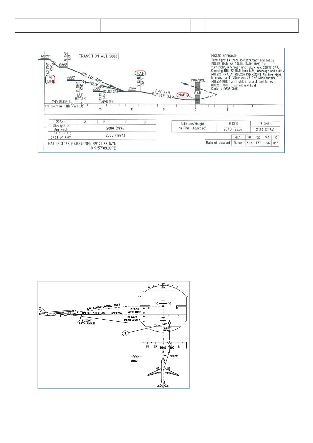
Picture 98: Vertical information for Rwy35-y for LGKR
This is the vertical information of the IAC Chart. Take note of the three things circled on the chart, namely IAF,
FAF or VIP, and MAPT.
The approach is divided into three following sections:
1.
IAF is the Initial Approach Fix, which denotes the start of Initial Approach.
2.
FAF is the Final Approach Fix and VIP (vertical Interception Point), which denotes the start of Final
Approach.
3.
MAPT is the Missed Approach Point. At this point, the pilot must GO AROUND if he doesn’t have visual
with the runway or if the approach is not stable at that point.
Note: DECEL point is usually in-between IAF and FAF.
7.7
Required PFD Symbology Knowledge
Before we begin the actual tutorial, you should know the basic PFD symbology that will be used on this
approach.
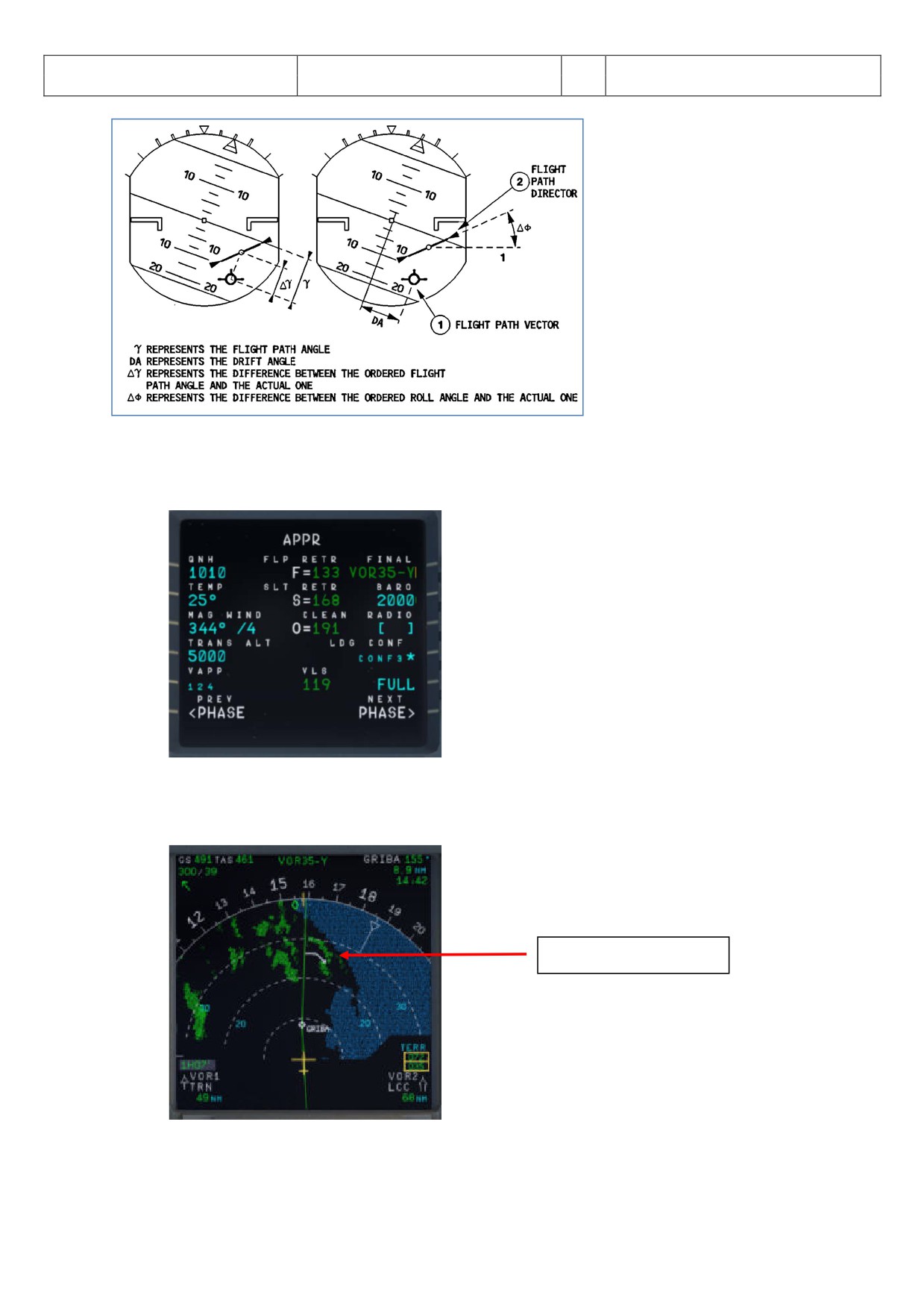
The illustration here on the left hand side
of the page explains the Flight Path Vector
and Flight Path Director, also known as the
FPV/FPD or Birdie. This symbology appears
when the pilot selects TRK/FPA on the FCU.
It is important to be able to read,
understand and interpret the FPV/FPD in a
timely fashion as workload during a NPA
can be quite high.
Picture 99: Flight Path Vector and Flight Path Director 1
Aerosoft
The Airbus A318/319/320/321 in FSX
Vol
06-01-09 Page 85
Airbus A318/319/320/321
Step-By-Step Tutorial
6
25 October 2015
Picture 100: Flight Path Vector and Flight Path Director 2
7.8 Descent Preparation and Descent
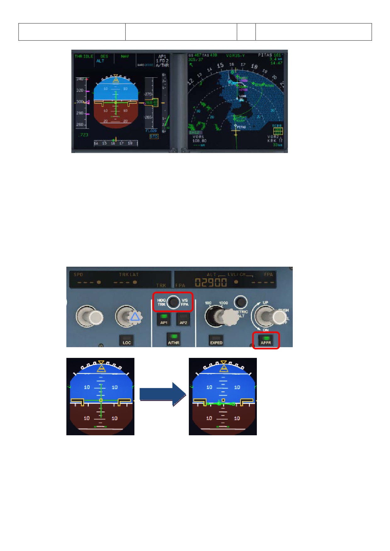
• Fill in the MCDU PERF Approach Page as follows:
QNH, TEMP and MAG/WIND are according to the
expected METAR data (6.3). The transition altitude
for LGKR is
5.000 feet and the BARO
= MDA
(minimum descent altitude) according to the chart =
2.000 feet.
Picture 101: MCDU PERF APPR page
• Set the “to descent to altitude” on the FCU to 2.900 feet = GAR09 where we will start our final
approach - but do not yet push the ALT knob.
• You will reach T/D app. a few miles before GRIBA.
Top of Descent (T/D)
Picture 102: Top of Descent
• Reaching T/D start descent by pushing the FCU ALT knob.
Aerosoft
The Airbus A318/319/320/321 in FSX
Vol
06-01-09 Page 86
Airbus A318/319/320/321
Step-By-Step Tutorial
6
25 October 2015
Picture 103: Descent Flight Path
7.9 Initial Approach Fix (IAF)
The IAF for LGKR VOR RWY 35-y is below 10.000 feet (please see chart - picture 67).
At IAF you should already have:
1.
Filled in the MCDU Approach Page (6.8).
2.
Already briefed on the Missed Approach Procedures.
3.
Be cleared by ATC for the approach
When passing the IAF, you should begin to setup your displays to give you the necessary information for your
approach. You should (in no particular order):
ARM the APPR as well as the TRK/FPA button on the FCU.
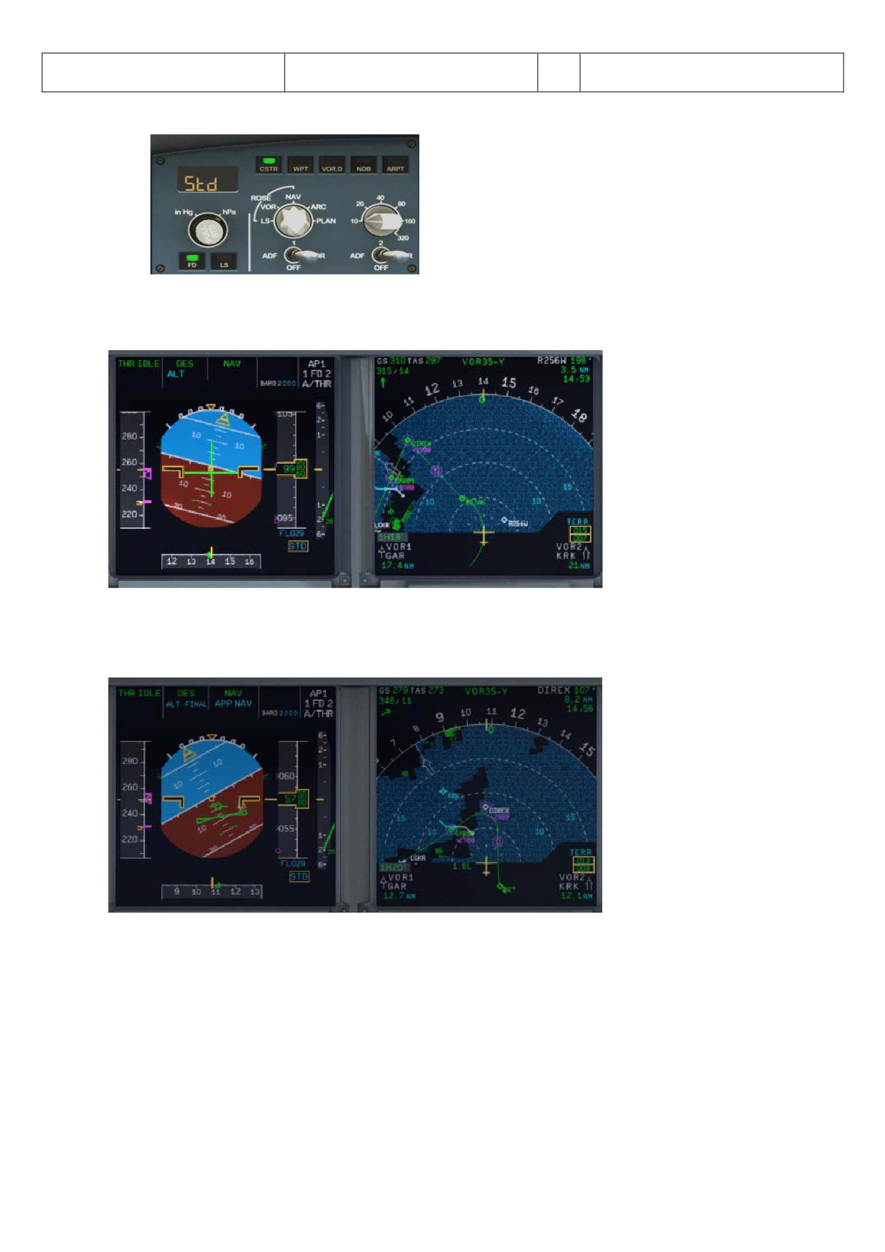
Pressing the TRK/FPA button on the FCU gets the birdie on the PFD.
Aerosoft
The Airbus A318/319/320/321 in FSX
Vol
06-01-09 Page 87
Airbus A318/319/320/321
Step-By-Step Tutorial
6
25 October 2015
Switch the ND to Rose Mode = Rose VOR or to Arc Mode and set range to an appropriate range.
Pressing the APPR button will arm the FINAL Mode on the MCDU which will provide FINAL APP vertical and
lateral guidance.
Picture 104: After passing 10.000 feet = IAF
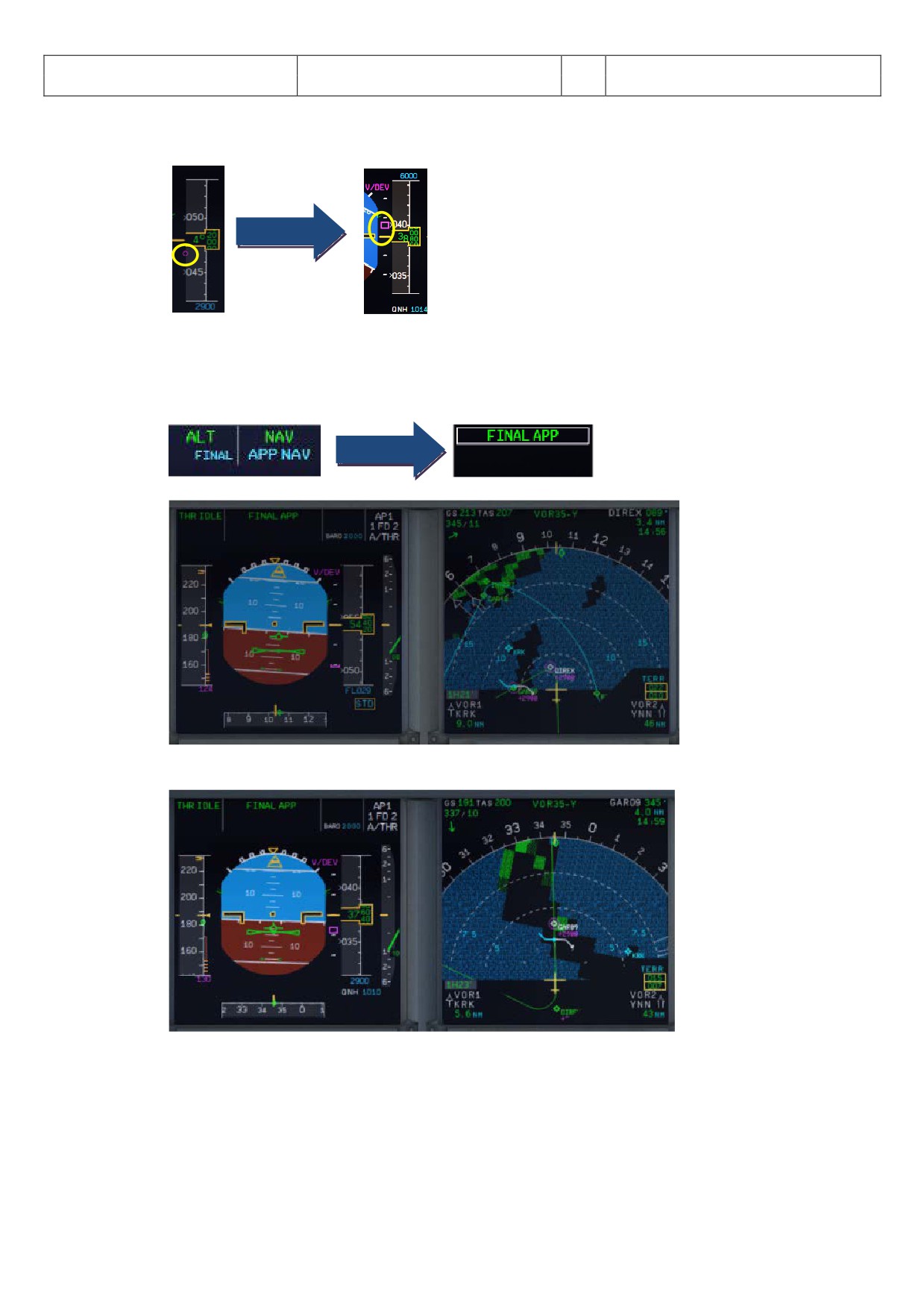
7.10 Deceleration Point
You will reach the DECEL point app. 3 NM before DIREX
Picture 105: Deceleration Point
Aerosoft
The Airbus A318/319/320/321 in FSX
Vol
06-01-09 Page 88
Airbus A318/319/320/321
Step-By-Step Tutorial
6
25 October 2015
After Passing DECEL,
• APPR Phase activates on the MCDU and the VDEV Scale replaces the VDEV magenta dot.
• We highly recommend using the speed brakes after activating the APPR PHASE until the magenta
square on the VDEV scale is in the middle of the scale as shown in the picture above.
• ALT and NAV FMA replaced by FINAL APP FMA.
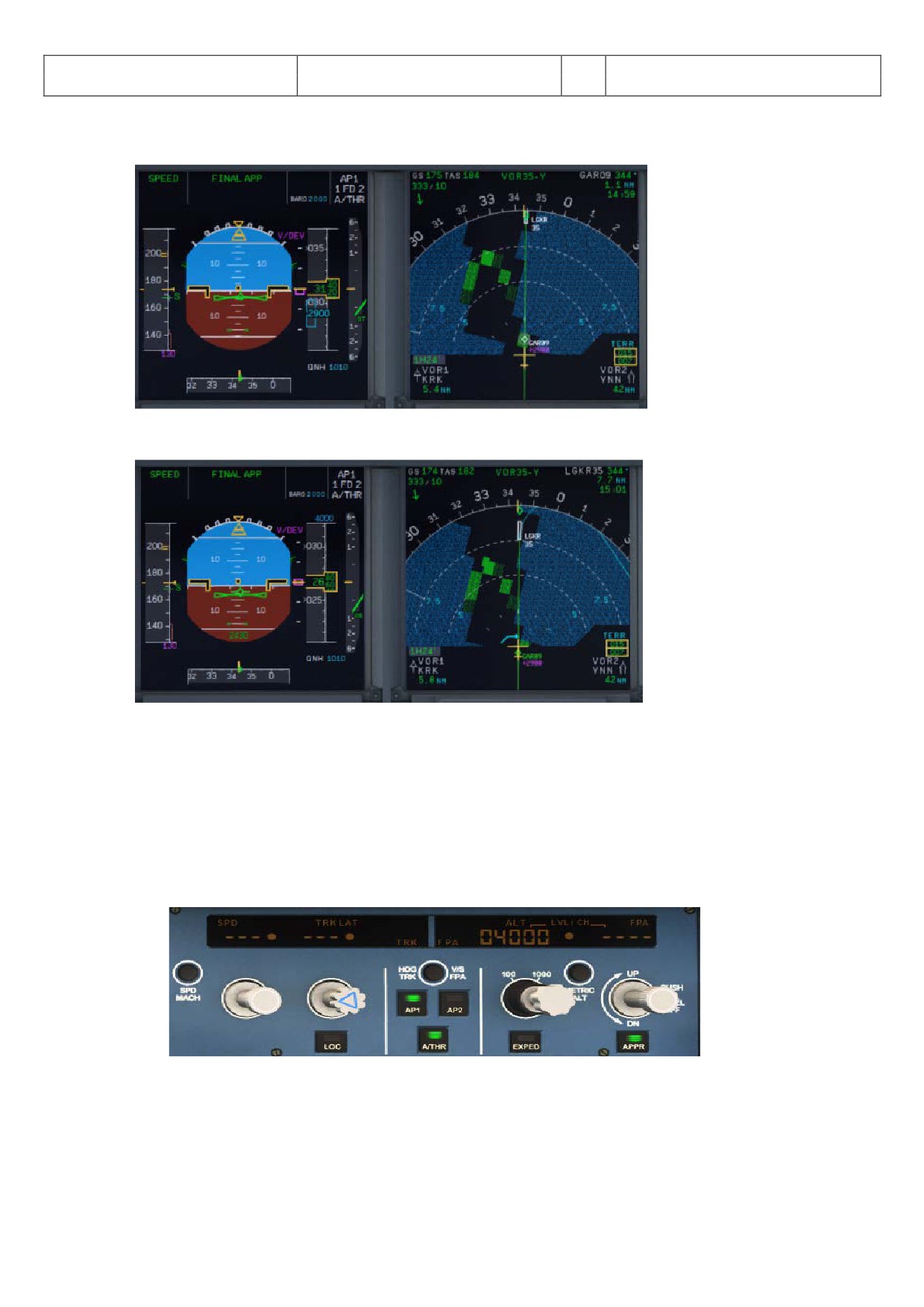
Picture 106: FINAL APP activated after passing DECEL Point
Picture 107: Passing DIREX - Direction GAR09 and LGKR VOR 35-y
• The Copilot should have prepared the plane for the final approach i. e. you are flying already with
FLAPS 1. Don't hesitate to use speed brake where deemed neccesary.
Aerosoft
The Airbus A318/319/320/321 in FSX
Vol
06-01-09 Page 89
Airbus A318/319/320/321
Step-By-Step Tutorial
6
25 October 2015
7.11
Final Approach Fix (FAF)
The FAF for LGKR VOR RWY 35-y is at GAR09 (please see chart - picture 80).
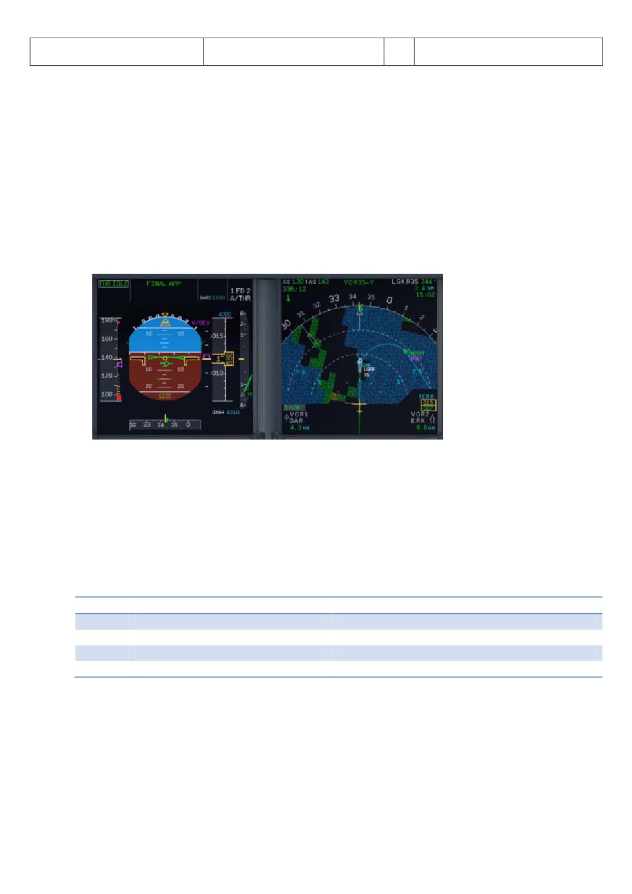
Picture 108: Before FAF = GAR09
Picture 109: Passing GAR09 = FAF
After Passing FAF the plane should start to descent following the V/DEV flight path.
• Check that FINAL APP is green on the FMA.
• Check A/THR Mode is SPEED Mode.
• Monitor Position and Flight Path is within acceptable limits.
• ECAM LDG Memo should be green.
• Set GA Altitude. (4000 is set according to the Missed Approach Instructions)
Aerosoft
The Airbus A318/319/320/321 in FSX
Vol
06-01-09 Page 90
Airbus A318/319/320/321
Step-By-Step Tutorial
6
25 October 2015
7.12
Minimum Decision Altitude (MDA)
At MAP/MDA (which is set to 2.000 feet)
• Check LDG MEMO is all green.
• Approach is stable.
• Visual with runway.
If those conditions are met the captain will announce "LANDING".
• Disconnect AP and proceed to fly manually
• Turn FD off
• Set TRK on the FCU to runway track (=345).
Failure to disconnect AP by MDA will result in automatic AP disconnection at MDA-50 ft. The PFD altitude
display after passing the MDA will change to “yellow”.
Picture 110: Manual Approach after passing MDA (ND = ARC mode)
If decision is to GO AROUND, announce "GO AROUND".
• Set the thrust levers to MAN TOGA
• Set the AP to ON
• Fly the Missed Approach path
If the checklist- and copilot funtions are set ON just follow the checklist……
7.13
Summary
AT
Position
Action
IAF
< 10.000 feet / 11.5 NM -> R256W
Arm APPR and TRK/FPA
D-Point
app. 7.5 NM before DIREX
V/DEV replaces “magenta dot” and FMA = FINAL APP
FAF/VIP
At GAR09
Plane starts to descent automatically
MDA
At 2.000 feet
Set AP and FD = OFF
Remember:
• If you are flying a GA-procedure in connection with an NPA please remember that compared to a normal
ILS-Approach below the Minimum Altitude the AUTOPILOT is OFF. So initiating the Go-Around you have to
set the AUTOPILOT again to ON.
• The same is valid in case of a new approach for the APPR. Set it to ON when clearing the F-PLAN
DISCONTINUITY between the last waypoint of the GA flightpath and the first waypoint of the new FINAL.
• During GA-procedure and in case of a new approach the automatic activation of the MCDU APPR PHASE
does not work. It has to be manually activated. There is also no DECEL-point displayed on the ND.
Aerosoft
The Airbus A318/319/320/321 in FSX
Vol
06-01-09 Page 91
Airbus A318/319/320/321
Step-By-Step Tutorial
6
25 October 2015
8.
A318 - Steep Approach
8.1 Introduction
This part is meant to serve as a simple A318 Steep Approach Guide to pilots, unfamiliar with all the tools the
airbus provides for such an approach. This part of the guide is edited by a real world Airbus A 320 pilot. But still
there might be some deviations from Real World Procedures.
MANAGED MODE
We are using for this “Managed Mode”.
8.2
Settings / Flightplan used for the Tutorial
We are using the A318 for this flight with a ZFW of app. 48.228 kg (80 passengers and 2.000 kg cargo) as well as
a fuel load of 7.419 kg (according to the Load-/Fuel-Planner - in Advanced Mode -).
The flight plan (using FL 310) will be as follows:
Departure:
EDDH (Hamburg/Germany) - Runway: 23 - SID: WSR9B
Flight:
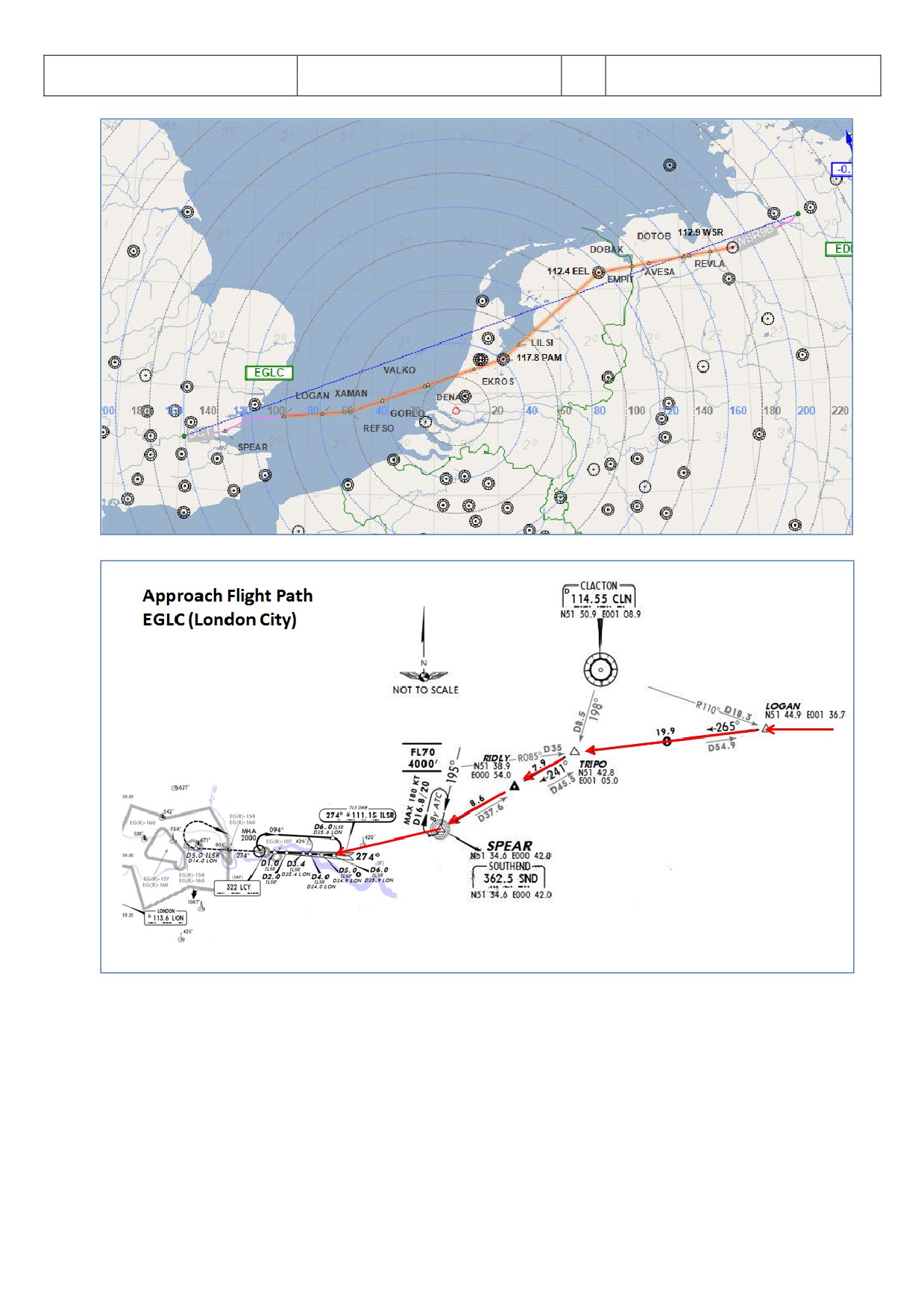
WSR N125 DOBAK UN125 EEL UN872 PAM UL980 XAMAN L980 LOGAN
Arrival:
EGLC (London-City/ Great Britain) Runway: 27 = ILS27 - STAR: SPEA1B
You can manually enter the flight plan or use the existing one EDDHEGLC01. But after loading there is a F-PLAN
DISCONTINUITY between SPEAR (end of STAR SPEA1B) and LSR06 (FINAL). Please CLR it.
8.3
Weather EGLC
The expected METAR data for our approach at EGLC are as follows:
QNH:
1021 HPa
Temperature:
20 degrees C
Wind:
At 270 degrees at 7 knots
Please adjust the FSX weather or add-on settings accordingly. If you do not know how to do this then just select
“Fair Weather” in FSX. This weather is perfect for using runway 27, so we will use ILS27 and STAR SPEA1B
(marked in red on the charts you will find in 7.5).
8.4
Checklist- and Copilot Function
We suggest using the Checklist as well as Copilot Function for this flight because then you are fully able to
concentrate on this Steep Approach procedure.
8.5
Flight path and Charts used for this Steep Approach at EGLC Rwy27
The flight path and charts we need for this approach you will find below. Additional charts for this approach can
be found here http://www.ukvirtual.co.uk/dl/charts/eglc.pdf.
Aerosoft
The Airbus A318/319/320/321 in FSX
Vol
06-01-09 Page 92
Airbus A318/319/320/321
Step-By-Step Tutorial
6
25 October 2015
Picture 111: Flight path EDDH - EGLC
Picture 112: STAR chart (SPEA1B) for EGLC
The approach is divided into three following sections:
• IAF is the Initial Approach Fix, which denotes the start of Initial Approach.
• FAP is the Final Approach Point (for ILS landings) and VIP (Vertical Interception Point), which denotes the
start of Final Approach.
• DA is the Decision Altitude at which the pilot must GO AROUND if he doesn’t have visual with the runway
or if the approach is not stable at that point.
Note: DECEL point is usually in-between IAF and FAP.
Aerosoft
The Airbus A318/319/320/321 in FSX
Vol
06-01-09 Page 93
Airbus A318/319/320/321
Step-By-Step Tutorial
6
25 October 2015
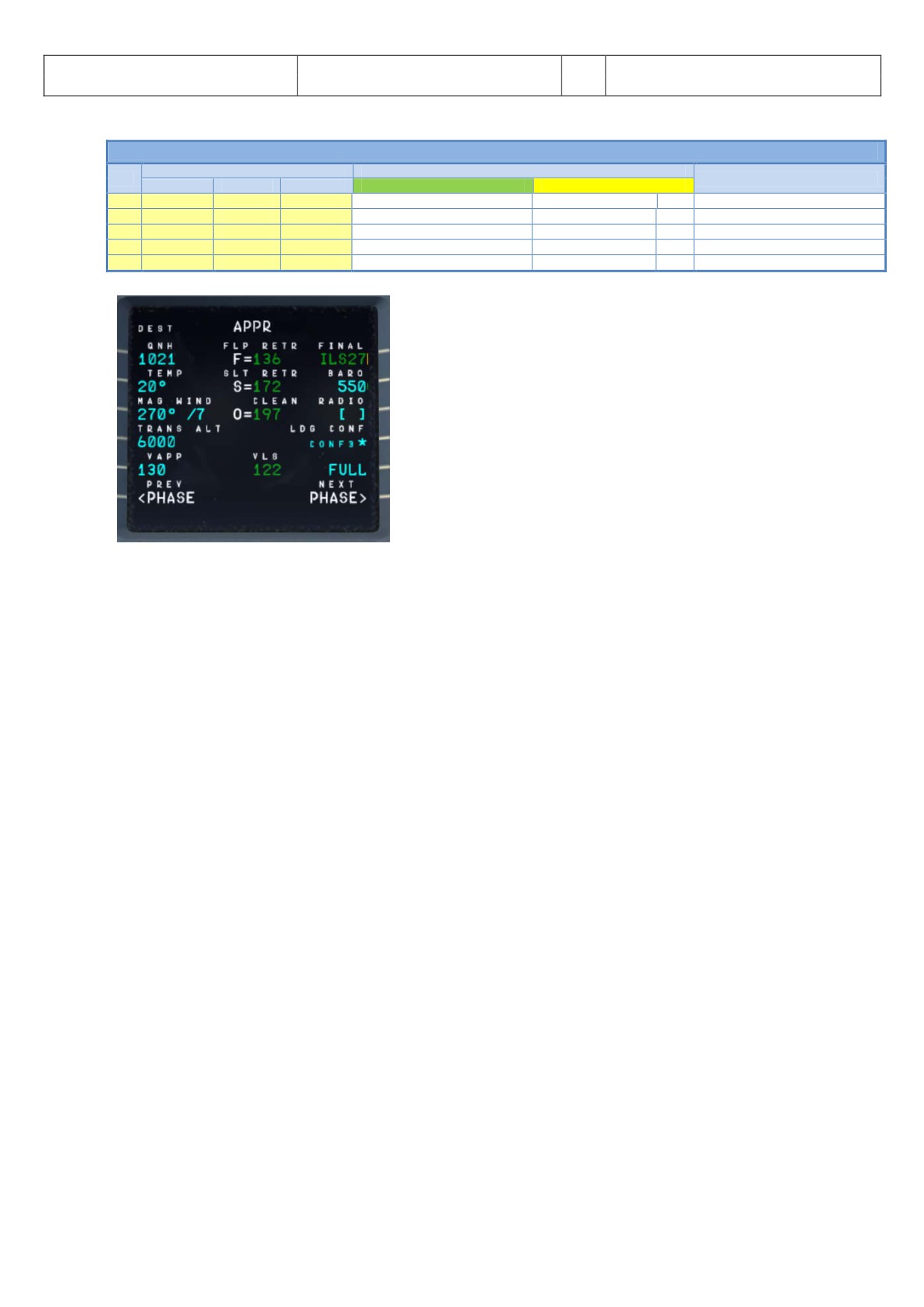
8.6 MCDU PERF APPR PAGE
MCDU PERF APPR PAGE
PANEL
ACTION
NO.
REMARK
TYP
PART (Name)
PART (No.)
PF (PILOT FLYING)
PM (PILOT MONITORING)
1
MCDU
PERF
APPR
QNH, TEMP, MAG WIND
ENTER DATA
2
MCDU
PERF
APPR
TRANS ALT
ENTER DATA
= 6000
3
MCDU
PERF
APPR
BARO / RADIO
ENTER DATA
= BARO 550
4
MCDU
PERF
APPR
VAPP
ENTER DATA
5
MCDU
PERF
APPR
LDG CONF
CHECK
Picture 113: MCDU PERF APPR page
1.
QNH; TEMP; MAG WIND: Enter data (for arrival airport EGLC) according to expected METAR data 7.3.
But if you use FSX “Fair Weather” then just enter QNH=1013/TEMP=20/and MAG/WIND=270/0.
2.
TRANSITION LEVEL: (TRANS ALT) for EGLC = 6000 feet (because it is different from transition altitude of
departure airport EDDH = 5.000) it has to be entered.
3.
BARO - DA (decision altitude): According to the chart for EGLC it is a CAT1 ILS approach. Do not get
confused by the CAT 3 FMA on the PFD. This FMA only tells you what the airplane is capable of, not
what the airport is offering. You can only fly a CAT 3 approach if both the FMA says CAT3 and the
airport has a CAT3 ILS.
As we are flying an ILS CAT1 landing at EGLC we have to enter a Barometric-altimeter DA (decision
altitude). Barometric-altimeter MDA/DA is used for NPA, RNAV as well as ILS CAT1 whereas RADIO-
altimeter DH (decision height) is used for ILS CAT2 and 3 landings. If there is no manual input a
standard BARO value of 200 will automatically be entered by the Copilot. But as the actual BARO-DA
value for our arrival airport EGLC (London City) Runway 27 and ILS approach is according to the charts =
550 so please enter this value.
The information about the available ILS CAT you can get from the charts. The category certification
entails a lot of things. The most important one for CAT2 and CAT3 is a monitoring of the validity of the
ILS signal and a backup power source. For charts there are a few different formats available but on
every ILS chart you will see the capability of the ILS by looking at the minimums. In LIDO charts it is
even spelled out CAT 1, Cat 2 etc. On Jeppesen/AIP charts you sometimes have an extra ILS CAT2/3
charts besides the ILS CAT 1 chart.
4.
VAPP: It is the final approach speed, will automatically be calculated / inserted by the system and
calculated in the following way: VLS plus 1/3 of the tower headwind component. The value of VAPP is
limited so that it is never less than VLS + 5 or more than VLS +15. As a result, VAPP is increased above
its minimum value for runway headwinds above 15 knots. VAPP correction is not increased further for
headwinds exceeding 45 knots.
For STEEP APPROACH into EGLC it is necessary to add another 3 KTS to the calculated VAPP.
5.
LDG CONF: (Landing Configuration) If no value is entered manually it defaults to FULL. For STEEP
APPROACH = FULL is required.
Aerosoft
The Airbus A318/319/320/321 in FSX
Vol
06-01-09 Page 94
Airbus A318/319/320/321
Step-By-Step Tutorial
6
25 October 2015
8.7 Descent Preparation
DESCENT PREPARATION
PANEL
ACTION
NO.
REMARK
TYP
PART (Name)
PART (No.)
PF (PILOT FLYING)
PM (PILOT MONITORING)
6
1 min after CRZ level has been reached
Start Checklist / Co-Pilot - if selected
7
SEAT BELTS = ON or AUTO
CHECK and set to ON
Cop
8
OVERHEAD
ANTI-ICE
8
ANTI ICE = OFF
CHECK
9
PEDESTAL
RADIO
1
LANDING INFORMATION
RECEIVED
If ATC is used
10
EFIS
A.PRESSURE
2
BARO REF = STANDARD
CHECK
Cop
11
OVERHEAD
STEEP APPR
18
STEEP APPROACH BUTTON
PUSH
12
BRIEFING “STEEP APPROACH”
PERFORM
13
MCDU
PERF.
APPR
AIR PRESSURE ARRIVAL AIRPORT
“Checked” and readout
Cop
QNH= 1021
14
MCDU
PERF.
APPR
DECISION ALTITUDE
“Checked”
Cop
BARO = 550
15
MCDU
PERF.
APPR
LDG CONF (Flaps)
"Checked"
CoP
Checklist complete
6.
DESCENT PREP. CL: It now can be manually started 1 min after reaching CRZ LVL. 40 NM before T/D
(CRUISE CL still active) - a specific information on the INFOBAR pops up also showing the distance to
the automatic start at 10 NM before the T/D. After the checklist has been finished a message on the
infobar pops up “INITIATE DESCENT”. Initiate descent when the T/D marker on the ND has been
reached.
7.
SEAT BELT SIGN : It is also OK if the switch is set to AUTO
8.
ANTI ICE: Should be OFF but if ANTI ICE is ON it is also accepted - condition then will be confirmed
10.
BARO REF: As we are flying higher than the “transition altitude” it should already be set to “Standard”
i.e. nothing has to be done.
11.
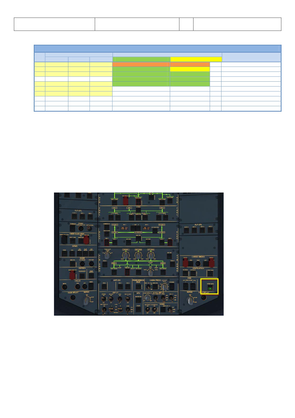
STEEP APPROACH button: Push the button on the Overhead so that it lights up and show ON in
green.
Picture 114: Overhead Panel and STEEP APPR button
When this P/B is pressed in, all concerned computers (ELAC, SEC, FCDC, FAC, FMGC, FWC,
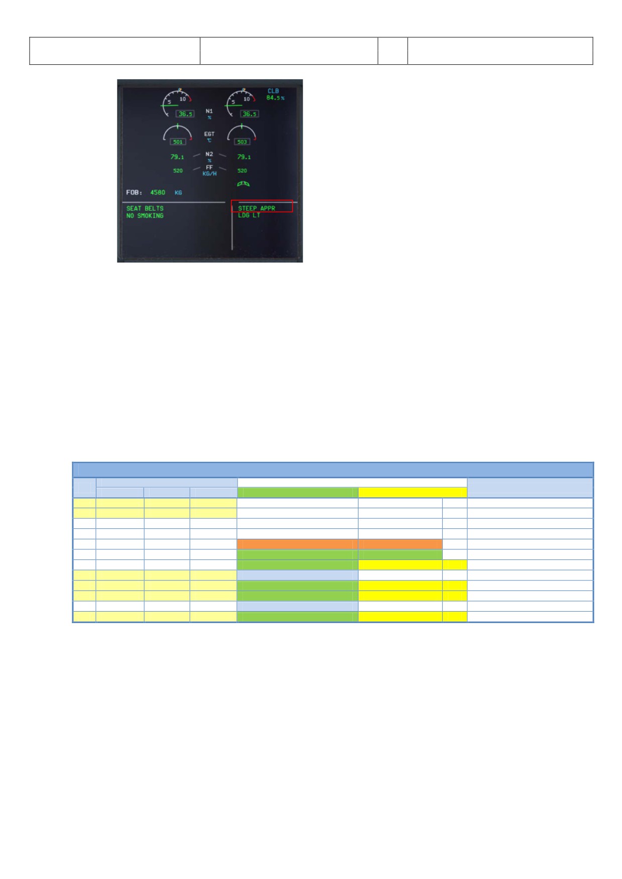
EGPWS/T2CAS) check if the STEEP APPR function is available. If yes, the P/B ‘ON’ light illuminates in
green, and the green memo ‘STEEP APPR’ appears on ECAM
Aerosoft
The Airbus A318/319/320/321 in FSX
Vol
06-01-09 Page 95
Airbus A318/319/320/321
Step-By-Step Tutorial
6
25 October 2015
Picture 115: UPPER ECAM - Steep Approach Button = ON
12.
Briefing “Steep Approach”: with the following key points:
• Landing configuration (STEEP APPR P/B pushed + Gear Down + CONF FULL + SPD BRKS lever
position FULL)
• VLSPFD=VREF+8Kt in steep approach configuration
• Automatic call-outs “Standby / Standby / Flare”
• PM call-out “Flare” at 60ft RA for redundancy with automatic “Flare” call-out at 63ft
• Retard thrust levers to IDLE at flare initiation
• Below 2000ft, Final Approach interrupted for Amber or Red warning except if immediate landing is
safer (fire or smoke)
• In case of Go Around, SPD BRKS lever must be retracted by PF (redundant action with automatic
retraction)
8.8
Descent
DESCENT
PANEL
ACTION
NO.
REMARK
TYP
PART (Name)
PART (No.)
PF (PILOT FLYING)
PM (PILOT MONITORING)
16
FCU
ALT
3
INSERT NEW HEIGHT
INSERT
= 4.000
17
FCU
ALT
3
INITIATE DESCENT
PUSH KNOB
18
MAIN PANEL
PFD
1
DESCENT
MONITOR
19
PEDESTAL
SP BRAKES
6
SET
AS REQUIRED
20
Vert. Mode = DES / Desc.Prep.CL = compl.
Starts next Checklist / Co-Pilot - if selected
21
MAIN PANEL
PFD
1
FMA
CHECK
22
PEDESTAL
TCAS
10
TCAS = TILT BELOW
CHECK and SET
CoP
23
At 10.000 feet:
24
OVERHEAD
EXT. LIGHTS
9
LANDING LIGHTS
ON
CoP
25
EFIS
FD / ILS
3
ILS LOCALIZER (LS)
PUSH
CoP
EFIS
26
At Transition Altitude
= 5000
27
EFIS
A PRESSURE
2
BARO REF to actual pressure value
SET / X CHECK
CoP
Checklist complete
16.
Descent to Altitude: Before the T/D (Top of Descent) point (near REFSO) is reached (marked on the
ND flight path by a white arrow showing down), the altitude should be set to 2.000 feet. But do not
push the knob before T/D is not reached
17.
Initiating Descent: There are various methods for descent but we will use:
Managed Mode:. Reaching T/D or if the T/D marker disappears or DECELERATE is displayed on the
PFD (whatever happens first): Just push the knob. The aircraft will now start to descend automatically
according to the flight path calculated in the MCDU - F-PLN.
Aerosoft
The Airbus A318/319/320/321 in FSX
Vol
06-01-09 Page 96
Airbus A318/319/320/321
Step-By-Step Tutorial
6
25 October 2015
T/D = 31.000 Feet
Picture 116: Top of Descent - Initiate descent
23.
At 10.000 feet: As soon as the altitude of 10.000 feet is reached the speed restriction of 250 knots
becomes valid. Therefore the aircraft automatically reduces the target speed to 250 knots already at
11.000 feet app. 9 NM before TRIPO.
10.000 feet Deceleration Point
Picture 117: ND: Deceleration Point
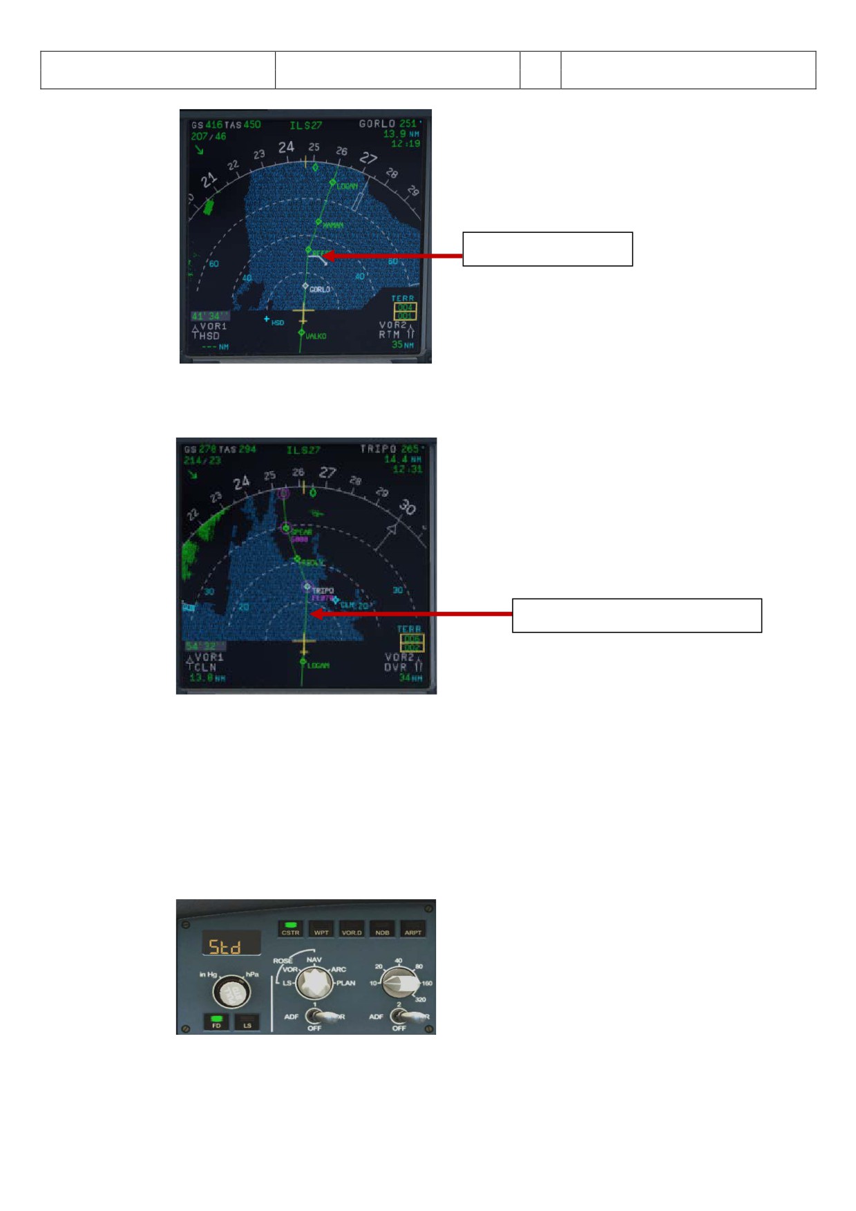
The IAF (Initial Approach Fix) for EGLC RWY ILS27 is below 5.000 feet e. g. at the waypoint SPEAR. At
this point = IAF you should already have:
4. Filled in the MCDU Approach Page (7.6).
5. Already briefed on the Missed Approach Procedures.
6. Be cleared by ATC for the approach
When passing the IAF, you should begin to setup your displays to give you the necessary information
for your approach. You should (in no particular order):
• Switch the ND to Rose Mode = Rose NAV or to Arc Mode and set range to an appropriate range.
Picture 118: Settings for ND mode and range
24.
LS Pushbutton: If the button is used (normally when passing 10.000 feet) the “Vertical Glideslope” as
well as the “Lateral Localizer” shows up on the PFD. The ND display shows ILS27 on top as soon as the
Aerosoft
The Airbus A318/319/320/321 in FSX
Vol
06-01-09 Page 97
Airbus A318/319/320/321
Step-By-Step Tutorial
6
25 October 2015
remaining distance to destination is 250 NM or less.
25.
Transition Altitude: Setting up the MCDU PERF APPR page we set it to 6.000 feet for the approach
(#2). So at this altitude the Barometric Reference Value will be set (as well as on ISIS) .
27.
Baro Ref Cross Check: The QNH value entered in the MCDU PERF APPR page is used by the copilot. If
no value has been entered there then the current ambient pressure value will be used (= keyboard
[B]). It is not mandatory to fill the QNH-field in the MCDU - PERF - APPR page. But if a value is
entered the unit used (inHg or hPa) must be identical with the settings the FCU - QNH display. If the
unit is later changed the value in MCDU PERF APPR page automatically will be adjusted. The FSX
standard conversion ratio of 1.013 = 29.92 is used for this baro function.
Like in reality the copilot enters those figures in visible steps and not at once. Then there is a pause of
2 seconds - during which the user can enter a different value - before the checklists continues.
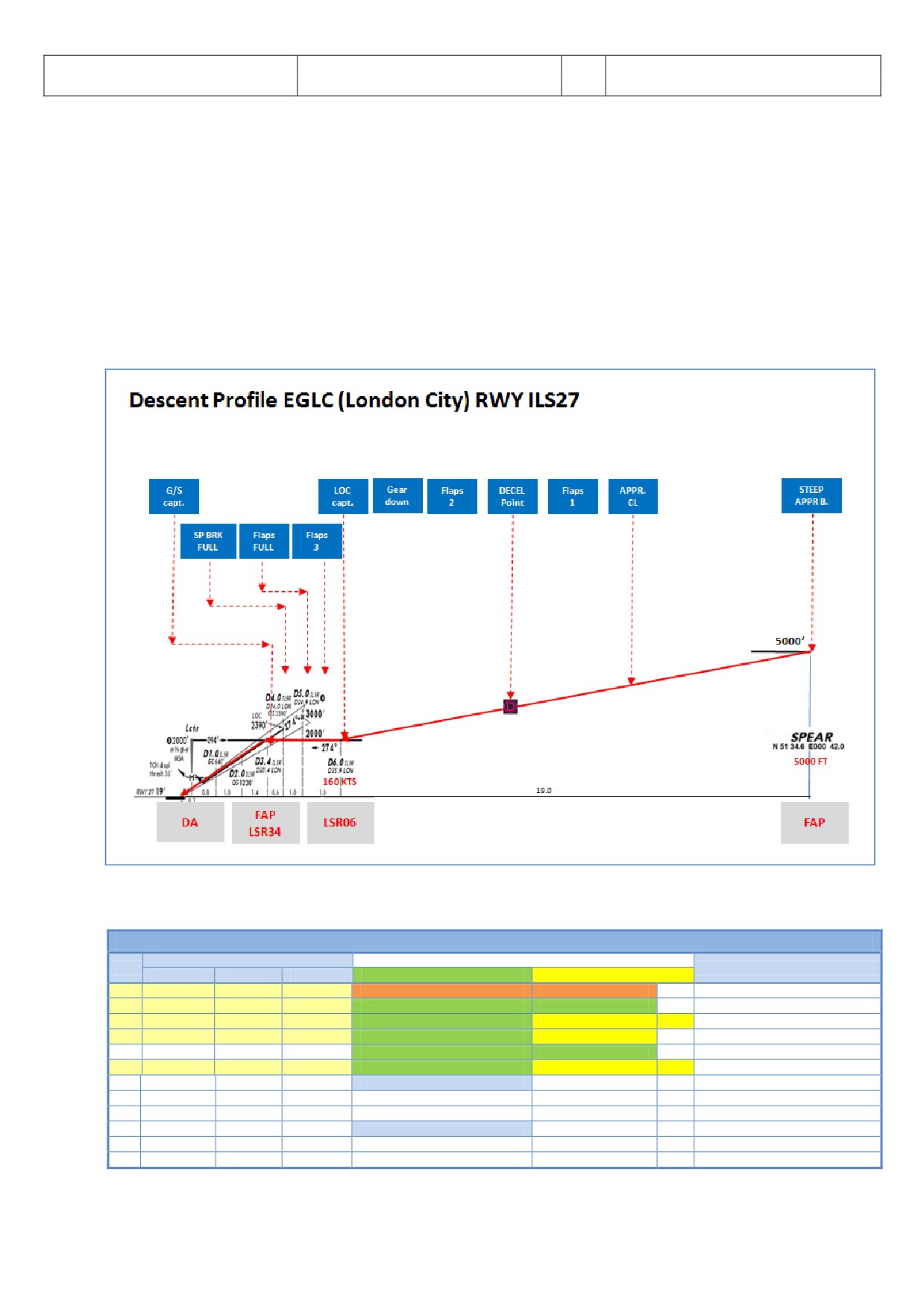
Picture 119: Descent Profile for RWY ILS27 into LGLC
8.9 Approach
APPROACH
PANEL
ACTION
NO.
REMARK
TYP
PART (Name)
PART (No.)
PF (PILOT FLYING)
PM (PILOT MONITORING)
28
5 NM before DECEL pseudo waypoint
Starts next Checklist / Co-Pilot - if selected
29
ECAM
ECAM
1
ECAM MESSAGE
CHECK
30
SLIDING TABLE S - STOWED
STOWED
CoP
31
OVERHEAD
SIGNS
11
CABIN SIGNS = ON
CHECK or set to ON
32
MCDU
PROG
NAV ACCURANCY
CHECK
33
EFIS
A.PRESSURE
2
BARO REF CROSS CHECK
SET and Read out
CoP
Checklist complete
34
Initial approach:
35
OVERHEAD
SIGNS
11
SEAT BELTS
CHECK ON
AUTO is also OK
36
PEDESTAL
ENGINE
5
ENG MODE
CHECK NORM
37
Approx. 15 NM from touchdown:
38
MCDU
PROG
NAV ACCURANCY
MONITOR
39
MAIN PANEL
PFD
1
POSITIONING
MONITOR
Aerosoft
The Airbus A318/319/320/321 in FSX
Vol
06-01-09 Page 98
Airbus A318/319/320/321
Step-By-Step Tutorial
6
25 October 2015
28.
Approach CL: The APPROACH CL now is available for manually start (MCDU2 CHECKLIST MENU =
marked in orange) app. 10 NM before the DECEL pseudo waypoint and a message pops up on the
INFOBAR showing the distance and explains the start options. It starts automatically app. 5 NM
before DECEL pseudo waypoint.
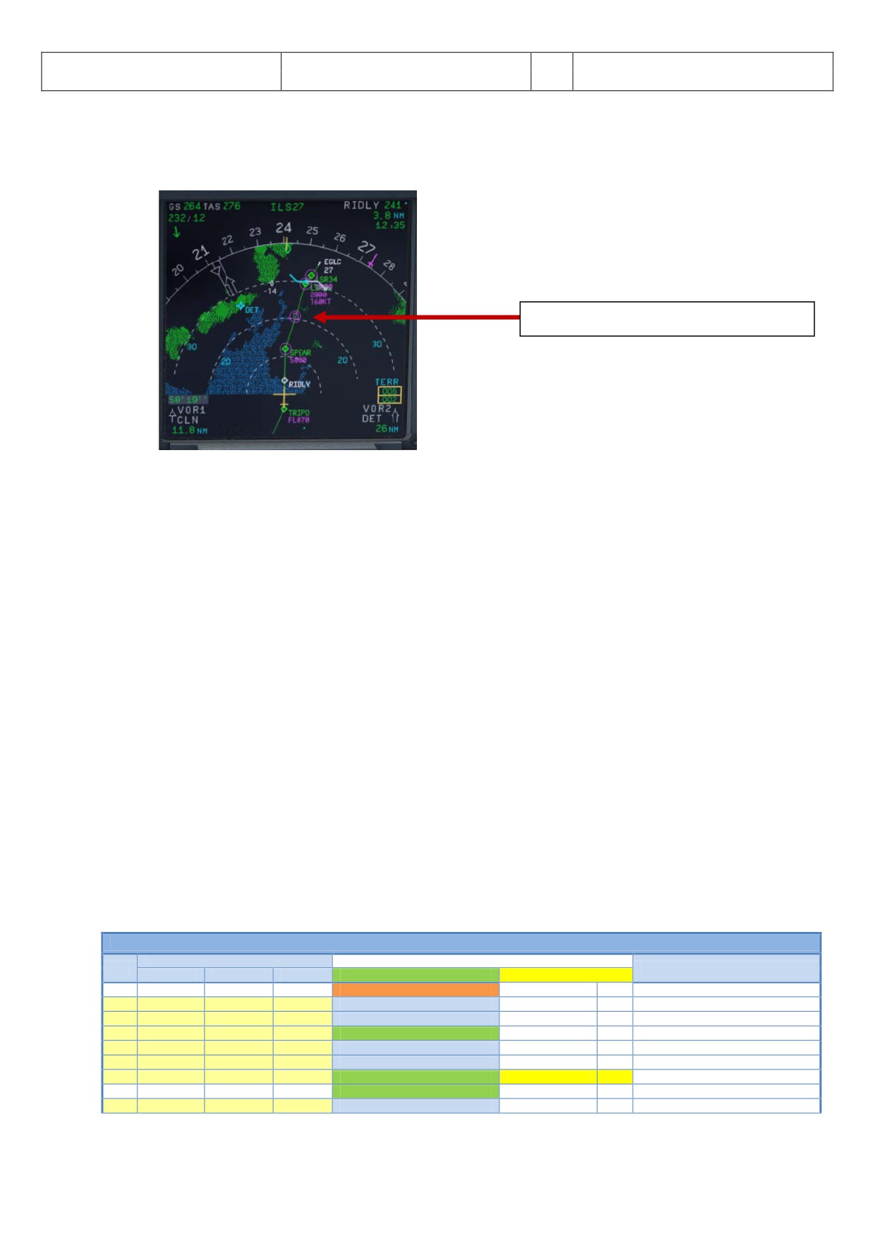
Deceleration Pseudo Waypoint Point
Picture 120: Decel Point
For the start of the APPROACH CL it is not necessary anymore that the DESCENT CL has been finished.
Even if the BARO CHECK has not yet been completed the APPROACH CL can be started. As a reminder
in such a case “DESCENT CL” blinks on the right MCDU.
29.
ECAM Message: There is a very important difference between caution (amber) and warning (red). If
the CLR button is ON it is necessary previously to confirm a “warning” or “caution” message.
30.
Sliding Table: If the copilots sliding table had been extended at cruise level. Even if the copilots
function is set to OFF now the captains and copilots sliding tables will automatically be retracted.
31.
Cabin Signs: SEAT BELTS=ON or AUTO (if OFF Cop sets to ON), NO SMOKING=ON
33.
Baro Ref Cross Check: The QNH value entered in the MCDU PERF APPR page is used by the copilot. If
no value has been entered there then the current ambient pressure value will be used (= keyboard
[B]). It is not mandatory to fill the QNH-field in the MCDU - PERF - APPR page. But if a value is
entered the unit used (inHg or hPa) must be identical with the settings the FCU - QNH display. If the
unit is later changed the value in MCDU PERF APPR page will be automatically adjusted.
Like in reality the copilot enters those figures in visible steps and not at once. Then there is a pause of
2 seconds - during which the user can enter a different value - before the checklists continues. The
FSX standard conversion rate of 1.013 = 29.92) is used for this baro function.
8.10
Final
There are two main modes for the approach: Using “Managed Speed” or “Selected Speed (manually)”. Our
Checklist- and Copilot-Function uses the “Managed Speed” mode. This means that the speed is automatically
set by the MCDU and the flaps are manually deployed by the Copilot (based on the situation).
The Final CL activation is “independent” from the activation of the MCDU - PERF - APPR mode activation. The
FINAL checklist will be automatically started after the APPR CL has been completed.
FINAL
PANEL
ACTION
NO.
REMARK
TYP
PART (Name)
PART (No.)
PF (PILOT FLYING)
PM (PILOT MONITORING)
40
Appr. CL has been completed
Starts next Checklist / Co-Pilot - if selected
41
MCDU
PERF
APPR PHASE
ACTIVATE
CoP
42
Green Dot Speed
43
PEDESTAL
FLAPS
8
FLAPS 1
SELECT
CoP
FSX: F7
44
S-Speed
45
EWD
STATUS
4
Rad. Alt. > 2.100 ft = LANDING MEMO
46
PEDESTAL
FLAPS
8
FLAPS 2
SELECT
CoP
FSX: F7
47
MAIN PANEL
GEAR
7
L/G DOWN
SELECT
CoP
FSX: G
48
MAIN PANEL
PFD
1
CALL: LOCALIZER ALIVE
Aerosoft
The Airbus A318/319/320/321 in FSX
Vol
06-01-09 Page 99
Airbus A318/319/320/321
Step-By-Step Tutorial
6
25 October 2015
49
FCU
APPR
6
APPR
PUSH
50
MAIN PANEL
PFD
1
CALL: LOCALIZER CAPTURED
CHECK
51
When L/G down, below REF SPEED
52
PEDESTAL
FLAPS
8
FLAPS 3
SELECT
CoP
FSX: F7
53
Next REF SPEED:
54
PEDESTAL
FLAPS
8
FLAPS FULL
SELECT
CoP
FSX: F7 / Checklist complete
55
PEDESTAL
SPEED-BR.
6
GROUND SPOILERS / SPEED BRAKE
FULL
CoP
56
FCU
ALT
4
GO AROUND ALT
SET TO 2.000 FEET
CoP
Just enter - do not push knob
57
OVERHEAD
EXT. LIGHTS
9
NOSE LIGHT (if not TAXI)
ON
CoP
58
MAIN PANEL
EWD
5
LANDING MEMO
CHECK NO BLUE
59
FCU
SPD
1
Set speed to VApp
SET
= 135 (MCDU - PERF - APPR page)
60
PEDESTAL
TCAS
10
TCAS
SET TO „TA ONLY“
61
MAIN PANEL
PFD
1
CALL: GLIDESLOPE ALIVE
62
MAIN PANEL
PFD
1
CALL: GLIDESLOPE CAPTURED
CHECK
63
MAIN PANEL
PFD
1
FMA
CHECK
64
MAIN PANEL
PFD
1
LOC / GS CAPTURE
MONITOR
65
ECAM
ECAM
1
ECAM WHEEL PAGE
CHECK
66
FCU
ATHR
7
A/THR
CHECK SPD
67
OVERHEAD
ANTI-ICE
8
WING ANTI ICE
CHECK OFF
For the first waypoint (LSR06) of the FINAL waypoints into EGLC ILS RWY27 there is a speed constraint of 160
KTS. To comply with this constraint the speed just after passing SPEAR and before activation of the approach
phase is already reduced to “Green Dot” speed (197 KTS). After “Green Dot” has been reached the flaps are
set to 1 and the speed is reduced to S-Speed of 172 KTS. To further reduce the speed Flaps 2 are set and the
plane starts to decelerates again to F-speed =136 knots. But because of the speed constraint at LSR06 of 160
knots we use “Selected Speed” e. g. draw the FCU SPD knob and set it to 160. After passing LSR06 please
change the speed to 135 knots VAPP (please see #59 for details). This procedure is different from the normal
procedure as stated below.
41.
Initiate Approach Phase:
After the APPROACH CL has been finished the APPR PHASE in the MCDU PERF APPR page
immediately should be manually activated (RW procedure).
If the MCDU F-PLAN DECEL pseudo waypoint (calculated by the FMGC to initiate deceleration in
order to be stabilized at VAPP at a specified point on the approach profile, normally at 1000 feet
AGL) is different from the point at which the APPR PHASE automatically will be initiated (7.200 feet
radar altitude), it is ILS or NPA approach and distance to the airport less than 30 NM) a warning will
appear on the INFOBAR “MCDU: Manually activate APPR PHASE”.
• Manually activated by the user (MCDU - PERF - APPR page) if warning appears on the INFOBAR
“MCDU: Manually activate APPR PHASE”. In the “real world” the APPR PHASE is always activated
manually and never automatically.
• Automatically at the Deceleration Pseudo Waypoint
(please see picture below) if the
APPROACH CL has been finished; the flight level is below 7.200 feet radar altitude, the RNAV
mode is active and the distance to the airport is less than 30 NM. The (DECEL) pseudo waypoint
is calculated by the FMGC to initiate deceleration in order to be stabilized at VAPP at a specified
point on the approach profile, normally at 1000 feet AGL.
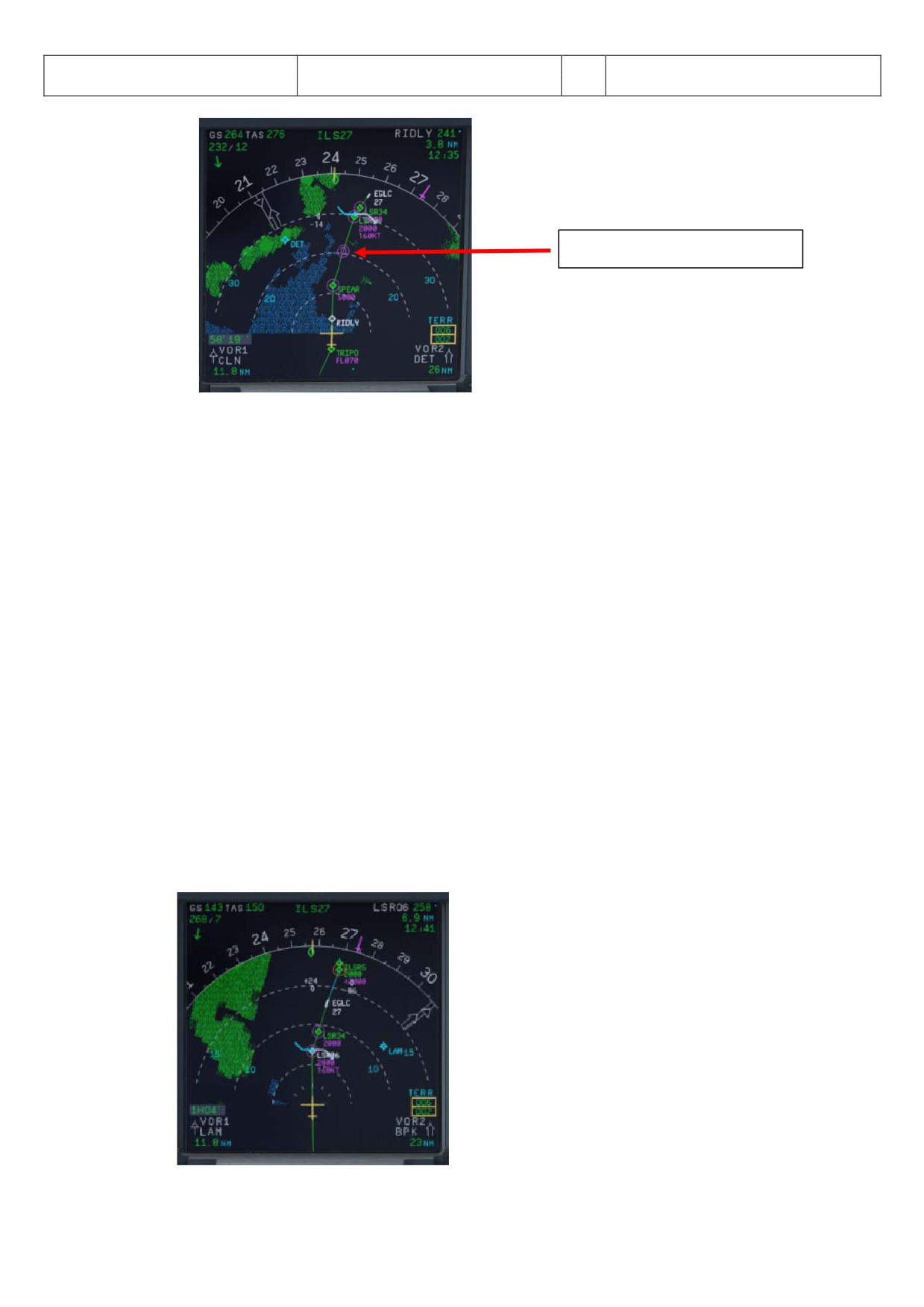
Aerosoft
The Airbus A318/319/320/321 in FSX
Vol
06-01-09 Page 100
Airbus A318/319/320/321
Step-By-Step Tutorial
6
25 October 2015
Deceleration Pseudo Waypoint
Picture 121: Deceleration Point
42.
Green Dot Speed / CLEAN: After initiating the APPR Phase (#41) automatically the MCDU reduces
the speed to “Green Dot Speed” (197 knots).
43.
Flaps: During the approach the flaps will be slowly step by step extended from 1 (after reaching
“Green Dot Speed”) to FULL based on aircraft speed - The flaps will be extended to 1 at least
automatically 10 NM before the runway threshold if IAS is below VFE.
44.
S-Speed: After the flaps are deployed by the Copilot to 1 the MCDU automatically reduces the speed
to S-Speed (172 knots). If the plane does not slow down to S-Speed then just use the speed brakes
until S-Speed is reached.
45.
Landing Memo: The conditions for the Landing Memo are:
•
< 2100 feet RA above runway altitude for STEEP APPROACH
•
Flight mode: Cruise or Approach
•
Both thrust levers at or below CL detent
The “LANDING” checklist is “interrupted” until the “Landing Memo” becomes available in the Upper
ECAM. The Copilot then continues with the settings i. e. flaps 2, gear down etc.
46.
Flaps 2: At calculated speed (but must be lower than VFE = 200 knots) the flaps are automatically
extended to 2 by the copilot (if = ON). If the calculated flaps 2 extension speed is higher than VFE
the plane must be near MLW or even above. This means it is an emergency situation. In such a case
do not use “Managed Speed”, but set the speed manually to a value below VFE = 200 knots (e.g. 195
knots). The flaps then will be automatically extended by the copilot (if = ON). After the flaps have
been extended to 2 you can again use “Managed Speed” for landing.
48.
LOC Alive: Before LSR06 the localizer becomes “alive” and this will be confirmed by a PM call
“LOCALIZER ALIVE”. The conditions for this call are: The angle to the runway must be smaller than
90 ° and the Approach, Landing as well as BaroCheck are not active.
Picture 122: FINAL Flight Path
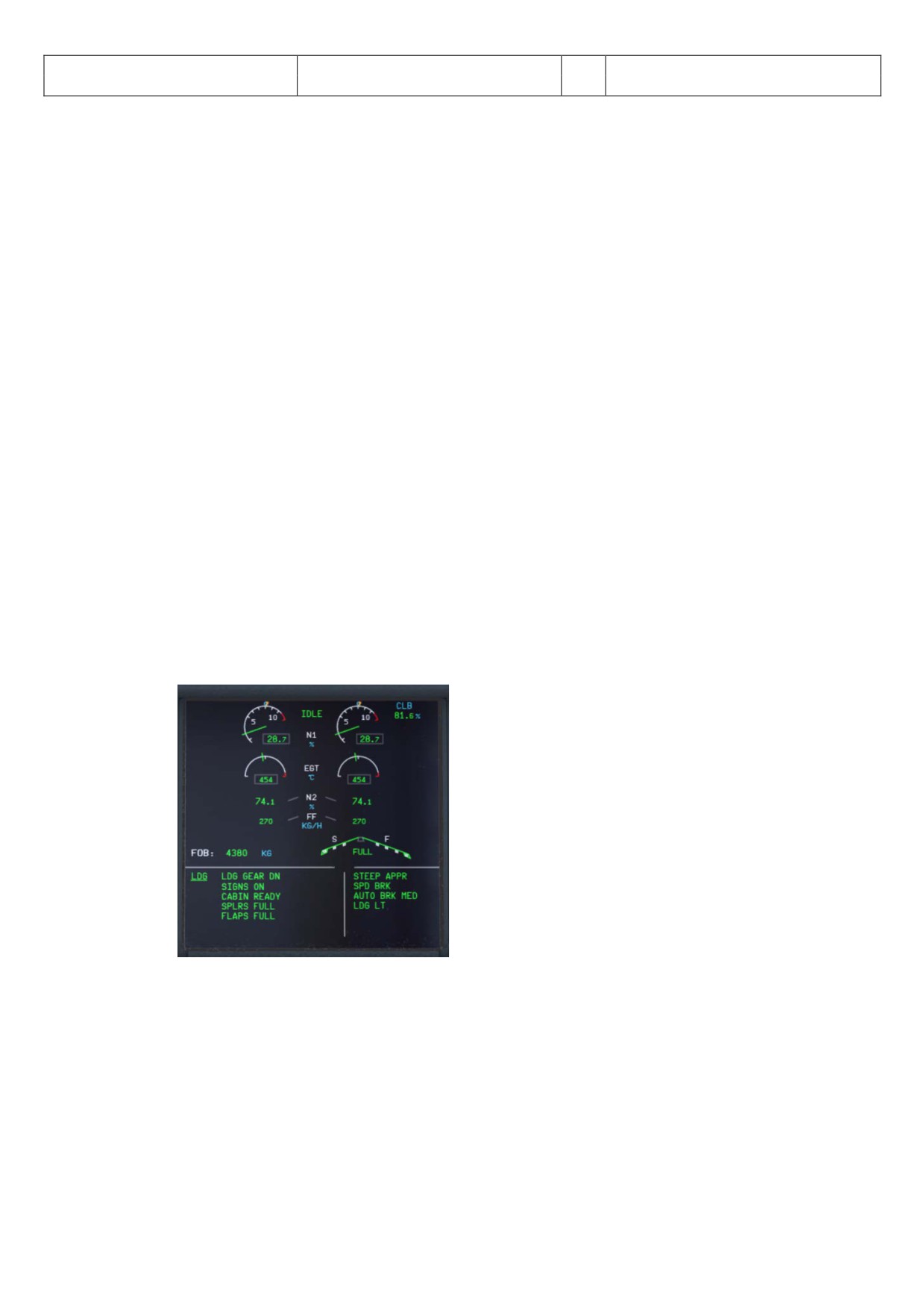
Aerosoft
The Airbus A318/319/320/321 in FSX
Vol
06-01-09 Page 101
Airbus A318/319/320/321
Step-By-Step Tutorial
6
25 October 2015
49.
APPR Button: Before passing LSR06 (you are already flying at LSR34) and after hearing the call
“LOCALIZER ALIVE” = press the APPR button on the FCU.
50.
LOC Capture: The “capture” will be confirmed i.e. lateral path has been caught. Please note: If you
are pushing the APPR button too early (before turning to LSR06/LSR34) it might happen that the
plane captures the localizer in the wrong direction. Please see also chapter 9.4 for details. First the
lateral path will be caught (LOC* or LOC displayed on the PFD -FMA)
55.
GROUND SPOILERS: For STEEP APPROACH it is necessary to set the Ground Spoilers (Speed Brakes)
to FULL.
56.
GoAround ALT: This is the altitude a plane has to fly to when using the GO AROUND procedure
(MCDU FPLAN waypoints in blue) in case a landing has to be aborted. Set the GoAround Altitude
according to the FPLAN e.g. change the set altitude on the FCU to the altitude to be reached after a
“Go Around”. Please just change the altitude and do not press or pull the knob at this point. In case
the Copilot function is enabled it is automatically set by the copilot under following conditions:
• FAF passed - plus 0.5 NM added
• Actual flight level below GA ALT
• Actual flight level below FCU set ALT
• Vertical speed below 250 knots
If the copilot function is set to ON the highest value is automatically inserted using the MCDU FPLAN
data. The value will be entered by the copilot in visible steps (with sound) and also considering the
100 and 1000 switch. Some values like 3.490 feet cannot be entered so the next possible higher
value which means for 3.490 = 3.500 has to be or are entered.
If no values are available in the F-PLAN or there is no GA flight path available in the NAV DB the
copilot sets the value to a value of (airport altitude rounded to next full 1.000) plus 4.000 feet e. g.
normally to 5.000 feet.
58.
Landing Memo / blue entries - : Please check if there are no “blue” entries in the Landing Memo. If
for some reasons there are still “blue” entries (you might have forgotten to make certain settings)
then please make those settings now.
Picture 123: Landing Memo - Steep Approach
59.
Set VAPP: After the flaps are set to FULL and the landing gear is down the speed now should be
changed to Vapp speed in our example to 130 as calculated by the FMGC - MCDU (PERF APPR) or
manually adjusted like in our case for a STEEP APPROACH (please also see #4). As we are flying in
“Managed Mode” the speed automatically is reduced to Vapp after the flaps are set to FULL - i.e.
nothing has to be done in “Managed Mode”.
But using this speed of 130 knots we would be very near Alpha Protection and PFD VLS. We
therefore suggest (like it would be done in “real life”) to use “selected speed” mode e.g. draw the
FCU SPD knob and set it to 135 knots instead.
It is the final approach speed and automatically be calculated / inserted by the system. It is
calculated in the following way: VLS plus 1/3 of the tower headwind component. The value of VAPP
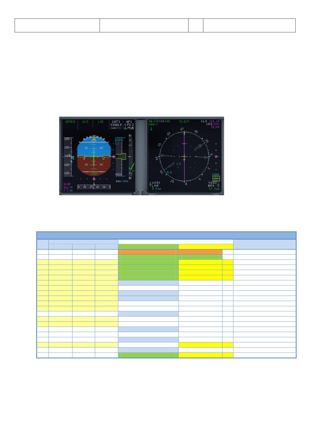
Aerosoft
The Airbus A318/319/320/321 in FSX
Vol
06-01-09 Page 102
Airbus A318/319/320/321
Step-By-Step Tutorial
6
25 October 2015
is limited so that it is never less than VLS + 5 or more than VLS +15. As a result, VAPP is increased
above its minimum value for runway headwinds above 15 knots. VAPP correction is not increased
further for headwinds exceeding 45 knots. No additions are made for gusts.
61.
Glideslope “alive”: When the Localizer has been captured (please see picture #70 above) soon after
the vertical glide slope becomes “alive” (magenta rhombus fully appears) which will be confirmed by
a call.
62.
Glideslope “captured”: When the glideslope has been captured it will be confirmed by a call.
The middle of both PFD fields shows the vertical and lateral position of the aircraft where as the
magenta rhombus shows the actual position on the glide path. This means that during the approach
both rhombuses are moving to the center. On the EFIS control panel please change the knob for the
various views to LS. This view also shows the glide path and the position of the aircraft to it.
Picture 124: G/S captured - LS view
66.
Auto Throttle: Leave the A/THR on…..
67.
Wing Anti Ice: Leave the Wing Anti Ice OFF
8.11
Landing
LANDING
PANEL
ACTION
NO.
REMARK
TYP
PART (Name)
PART (No.)
PF (PILOT FLYING)
PM (PILOT MONITORING)
68
Flaps in Landing Config. (MCDU Settings)
Start next Checklist / Co-Pilot - if selected
69
MAIN PANEL
GEAR
7
LAND. GEAR = FULL EXTRACTED
CHECK
CoP
70
PEDESTAL
SP. BRAKEs
6
GROUND SPOILERS = FULL
CHECK
CoP
FSX: Right mouse click
71
MAIN PANEL
AUTO BRAKE
6
AUTO BRAKES = MEDIUM
SET
CoP
72
OVERHEAD
EXT. LIGHTS
9
NOSE = TO or TAXI / LANDING L. = ON
CHECK
CoP
73
FCU
ALT
3
GO AROUND ALT
CHECK
CoP
74
BEFORE OR AT DECISION ALTITUDE
75
FCU
AP
5
AP
OFF
CoP
FSX: Z
76
CALL: STANDBY - STANDBY - FLARE
77
At 60 feet: (PM CALL = FLARE”)
78
FLARE
PERFORM
79
PEDESTAL
THR LEVER
4
THRUST LEVERS
IDLE
FSX: F1
80
At touchdown:
81
PEDESTAL
THR LEVER
4
REV
MAX
FSX: F2
82
BRAKES
AS REQUIRED
83
At 70 knots:
84
PEDESTAL
THR LEVER
4
REV
IDLE
FSX: F1
85
At taxi speed:
86
PEDESTAL
THR LEVER
4
REV
STOW
CoP
87
Before 30 knots:
88
MAIN PANEL
AUTO BRAKE
6
AUTOBRK
DISENGAGE
CoP
Checklist complete
70.
Ground Spoilers: Speed Brakes should already be set to FULL (see #55)
71.
Auto Brake: Set to MED (medium)
72.
Exterior Lights: Just check if all Exterior Lights are on: Strobe, Beacon, Nav & Logo as well as Landing
Lights.
Aerosoft
The Airbus A318/319/320/321 in FSX
Vol
06-01-09 Page 103
Airbus A318/319/320/321
Step-By-Step Tutorial
6
25 October 2015
73.
Go Around Altitude: Check if the GA has been set correctly according to #56.
74.
BARO - DA (decision altitude): Please also see #3 - for EGLC ILS 27 according to the charts = 550 feet.
At an altitude of 650 feet there will be a call “100 ABOVE”.
75.
Autopilot: Because EGLC ILS27 is ILS CAT1 we are not allowed to use “AUTOLAND” and have to
disconnect the autopilot at latest at the decision altitude of 550 feet.
76.
Standby - Standby - Flare: Beginning at 130 feet start automatic call-outs “Standby / Standby / Flare”
confirmed by the PM at 60 feet. Initiate FLARE at those calls e. g. at 55 feet.
77.
PM CALL “Flare”: At 60 feet redundant to the automatic call at 63 feet the PM confirms with “Flare”.
78.
LAND and FLARE mode: As the aircraft gets closer to the ground the LAND mode engages. The actual
modes are shown on the FMA. Flare has to be initiated manually at 55 feet.
79.
Thrust Levers: IDLE: There is a callout: RETARD (for SPEED APPROACH at 60 feet ). A single callout if
thrust levers are retarded in time, multiple callouts if not. Pull the trust levers back to IDLE at flare
initialization and let the aircraft gently touch the ground.
81.
Trust Levers: REV: After touchdown the thrust reversers (by using F2 from the keyboard) might be
activated but not necessarily if a noise abatement procedure prohibits it.
82.
BRAKES: The autobrake makes the aircraft decelerate on the ground. You can also take the control at
any time by using the brakes. Any manual action on the brakes automatically disconnects the
autobrake system.
86.
Thrust Levers: STOW: If REV THRUST is used (#81 and #84) the levers are automatically stowed by the
Copilot.
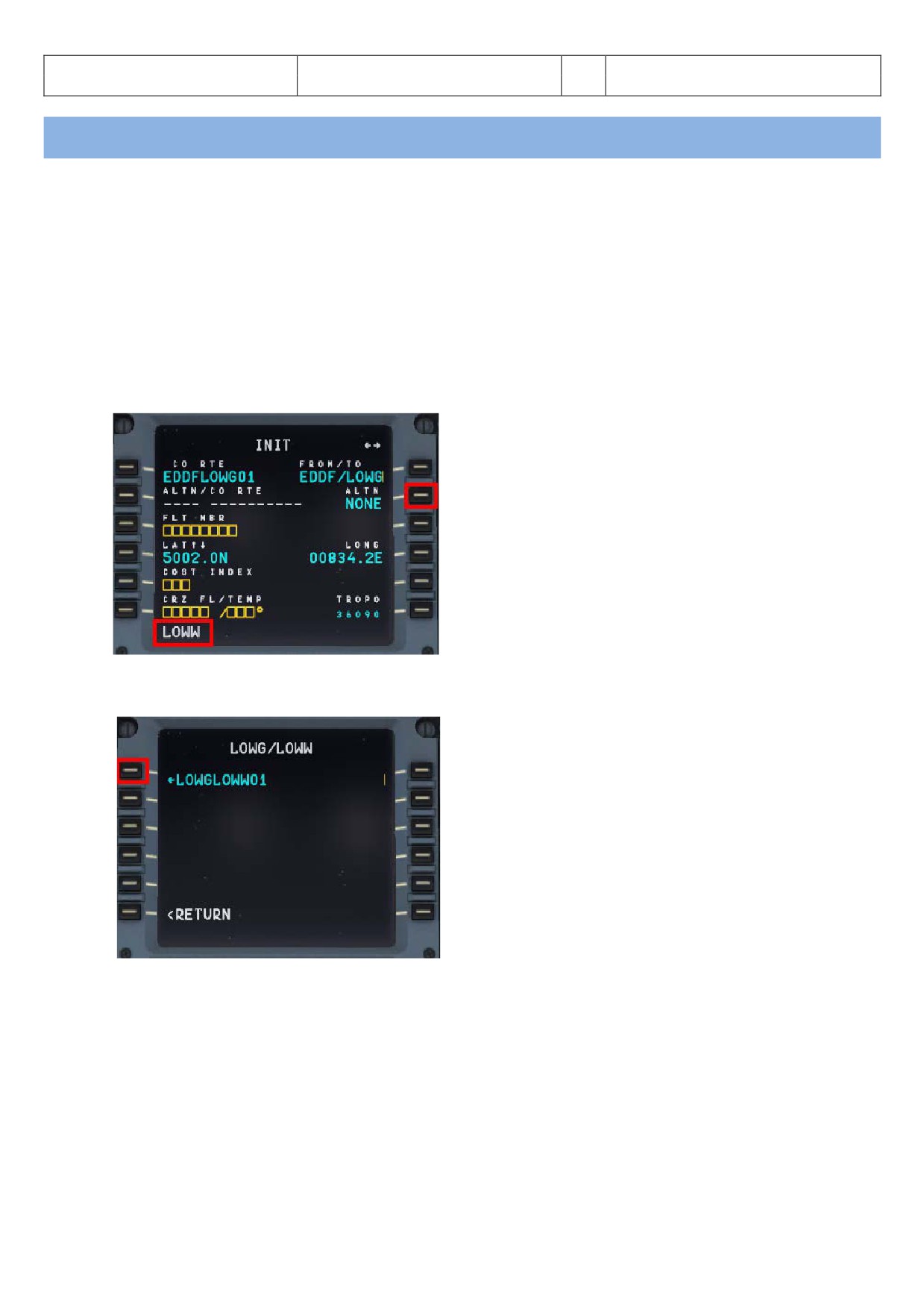
Aerosoft
The Airbus A318/319/320/321 in FSX
Vol
06-01-09 Page 104
Airbus A318/319/320/321
Step-By-Step Tutorial
6
25 October 2015
9. Alternate Company Routes and Destinations
9.1
Alternate Company Routes
An alternate company route is a flightplan (company route) from the primary destination to an alternate
destination. The format and the location where those flightplans are saved are identical with those of primary
flightplans.
For our tutorial we use as a primary flightplan EDDFLOWG01 e.g. from EDDF (Frankfurt/Germany) to LOWG
(Graz/Austria). As alternate flightplan we will use LOWGLOWW01 e. g. from LOWG (Graz/Austria) to LOWW
(Vienna/Austria).
Load the primary flight plan EDDFLOWG01 and then on the MCDU INIT A page enter LOWW into the
scratchpad and then push LSK 2R.
Picture 125: Entering ALTN destination - step 1
This following page displays all the existing flightplans from LOWG to LOWW. Please select LSK 1L.
Picture 126: Entering ALTN destination - step 2
The MCDU INIT A page then looks as follows:
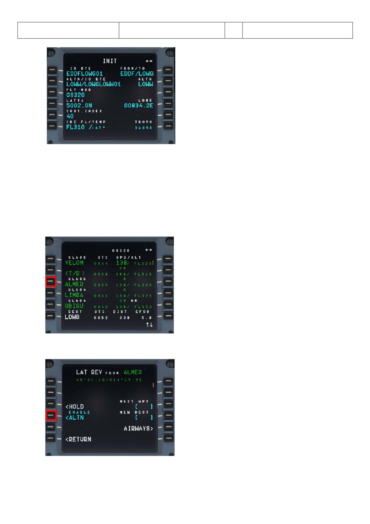
Aerosoft
The Airbus A318/319/320/321 in FSX
Vol
06-01-09 Page 105
Airbus A318/319/320/321
Step-By-Step Tutorial
6
25 October 2015
Picture 127: Entering ALTN destination - step 3
Now the two flightplans are loaded and can be reviewed on the F-PLAN pages. The primary flightplan is
displayed in “green” whereas the GA waypoints and the alternate flightplan are displayed in “blue. Both
flightplans are separated by ------ END OF F-PLAN -------.
If for any reason ATC informs you that the airport in Graz is closed and you receive the ATC-permission to
divert at the revise point of ALMER to LOWW = Vienna. The information could be like “Cleared to divert to
LOWW, from ALMER direct to NERDU and use approach transition NER5L for runway 16”. Then do the
following: Scroll in the primary flightplan to the waypoint of ALMER and push the LSK L (in following
screenshot = LSK 3L).
Picture 128: Enabling ALTN DEST - step 1
Enable the alternate destination by pushing LSK 4L.
Picture 129: Enabling ALTN DEST - step 2
Then the following screen opens:
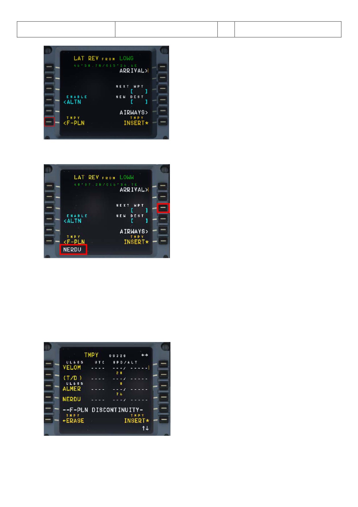
Aerosoft
The Airbus A318/319/320/321 in FSX
Vol
06-01-09 Page 106
Airbus A318/319/320/321
Step-By-Step Tutorial
6
25 October 2015
Picture 130: Enabling ALTN DEST - step 3
Enter NERDU into “NEXT WPT” and push LSK3R
Picture 131: Entering NERDU as NEXT WPT after the revise point ALMER
Automatically you are then back to the temporary flightplan page.
If at any enroute waypoint of the active flightplan (except FROM) the alternate flightplan is enabled (please
see the picture #89) - the flightplan shrinks to:
• Active route until the revise point = ALMER in our example
• Waypoint entered as next waypoint = NERDU in our example
• F-PLAN DISCONTINUITY
• Complete alternate company route
Picture 132: Temporary flight plan after enabling ALTN
If another waypoint is entered after the revise point = ALMER and before the F-PLAN DISCONTINUITY (in our
example = NERDU) and this waypoint is also part of the alternative company route then the flightplan
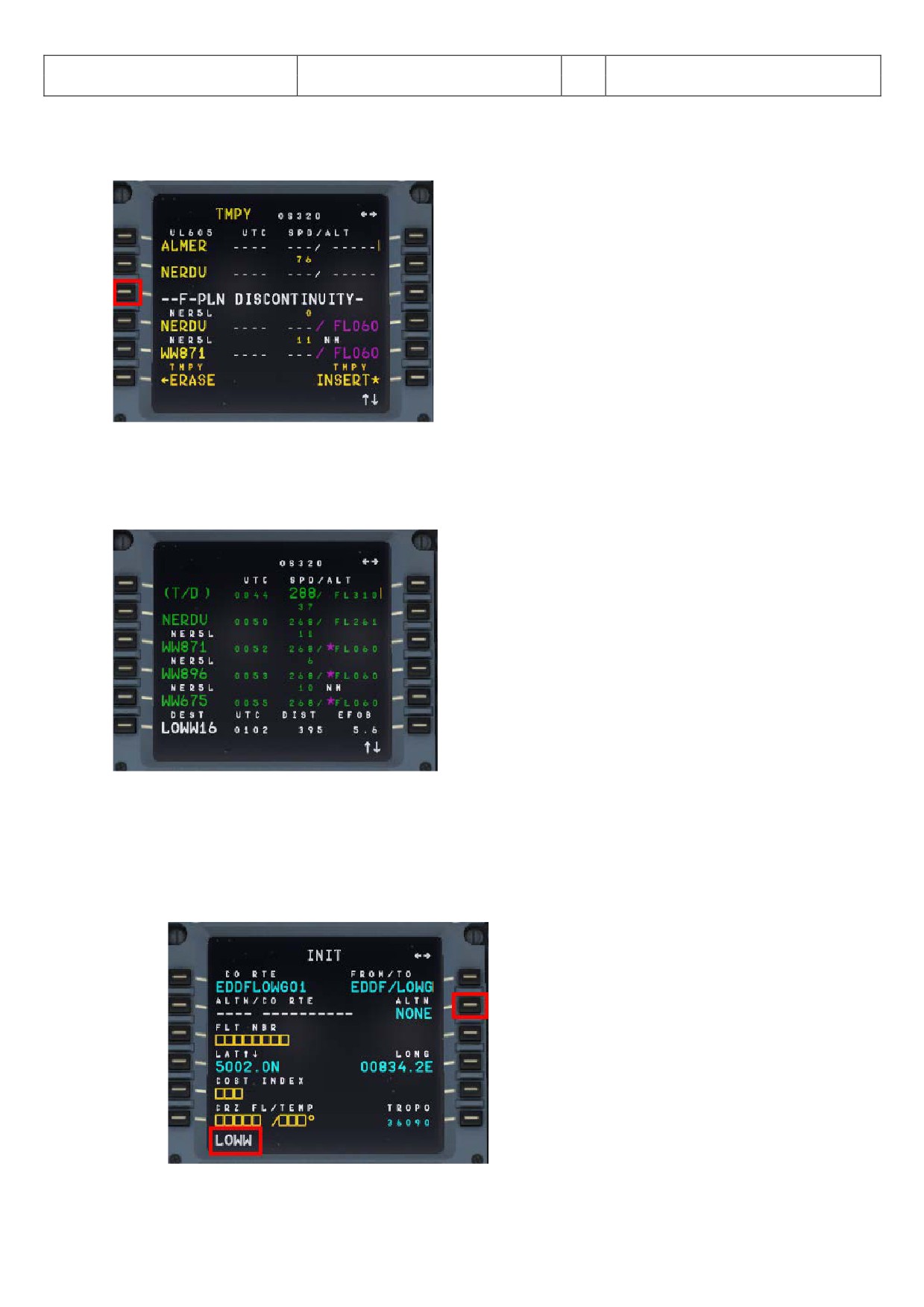
Aerosoft
The Airbus A318/319/320/321 in FSX
Vol
06-01-09 Page 107
Airbus A318/319/320/321
Step-By-Step Tutorial
6
25 October 2015
collapses. E. g. all waypoint of the alternate company route until this waypoint (= NERDU) are automatically
deleted.
Picture 133: Temporary F-PLAN after matching with ALT RTE
Clear the F-PLAN DISCONTINUITY (LSK 3L) and insert this temporary flightplan (LSK 6R). The alternate flightplan
now becomes the active primary flightplan.
Picture 134: Primary F-PLAN
9.2
Alternate Destinations
If no ALT CO RTE is available (or we do not want to use it) we just work with ALTN destination.
• Load the primary flightplan EDDFLOWG01
• Enter “LOWW” into the MCDU INIT A page as ALTN = LSK 2R
Picture 135: Entering ALTN DEST = LOWW
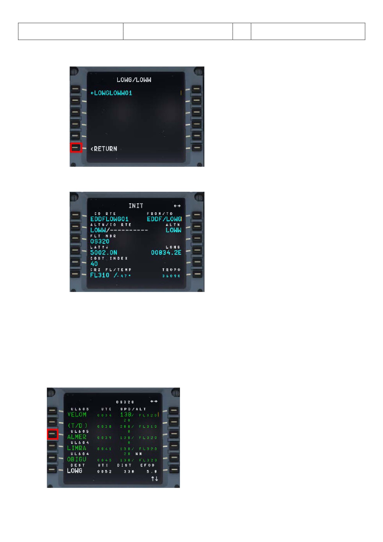
Aerosoft
The Airbus A318/319/320/321 in FSX
Vol
06-01-09 Page 108
Airbus A318/319/320/321
Step-By-Step Tutorial
6
25 October 2015
• As we will not use the existing ALTN CO RTE “LOWGLOWW01” please just go back to the INIT A page (
(=RETURN LSK 6L).
Picture 136: Not using existing CO RTE
• The INIT A page then looks as follows
Picture 137: INIT A page with ALTN destination
Now the two flightplans are loaded and can be reviewed on the F-PLAN pages. The primary flightplan is
displayed in “green” whereas the GA waypoints and the alternate flightplan (or just destination) are displayed
in “blue. Both flightplans are separated by ------ END OF F-PLAN -------. The alternate flightplan LOWG to LOWW
is also separated by a -----F-PLAN DISCONTINUITY ------ because no waypoints etc. are yet defined.
If for any reason ATC informs you that the airport in Graz is closed and you receive the ATC-permission to
divert at the revise point of ALMER to LOWW (Vienna) the information will be like “Cleared to divert to LOWW,
from ALMER direct to NERDU and then use transition NER5L for runway 16”. Then do the following: Scroll in
the primary flightplan to the waypoint of ALMER and push the LSK L (in following screenshot = LSK 3L).
Picture 138: Enabling ALTN DEST - step 1
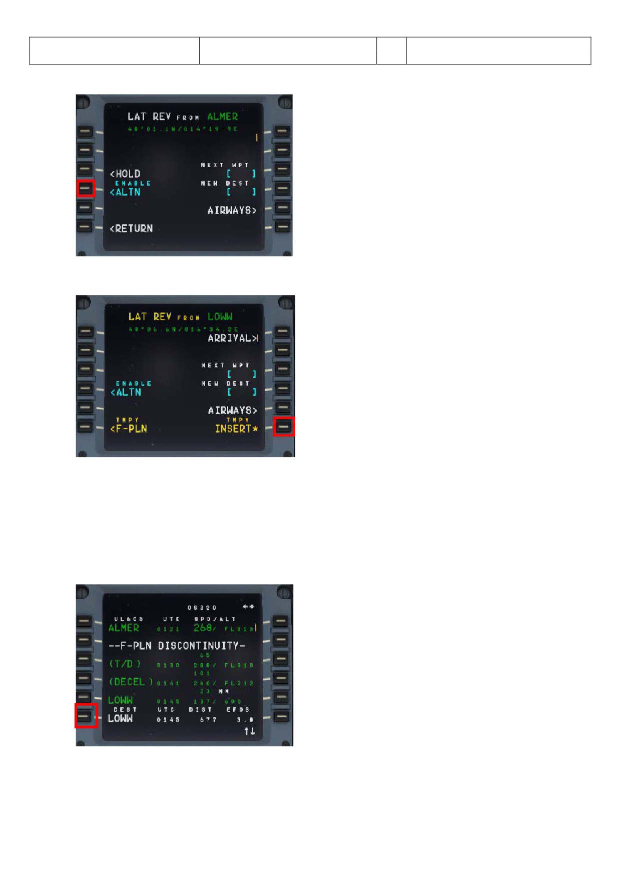
Aerosoft
The Airbus A318/319/320/321 in FSX
Vol
06-01-09 Page 109
Airbus A318/319/320/321
Step-By-Step Tutorial
6
25 October 2015
Enable the alternate destination by pushing LSK 4L.
Picture 139: Enabling ALTN DEST - step 2
Then the following screen opens:
Picture 140: Enabling ALTN DEST - step 3
Go back to the F-Plan and use TMPY INSERT = LSK 6R. The alternate flightplan now becomes the active primary
flightplan.
If at any enroute waypoint of the active flightplan (except FROM) the alternate flightplan is enabled (please
see the picture #98) - the flightplan shrinks to:
• Active route until the revise point = ALMER in our example
• F-PLAN DISCONTINUITY
• Alternate destination = LOWW
Picture 141: Active flight plan after enabling ALTN
Select the ARRIVAL for LOWW (LSK 6L) = ILS16 - no STAR - but just transition for runway 16 = NER5L and insert
the temporary flightplan (LSK 6R).
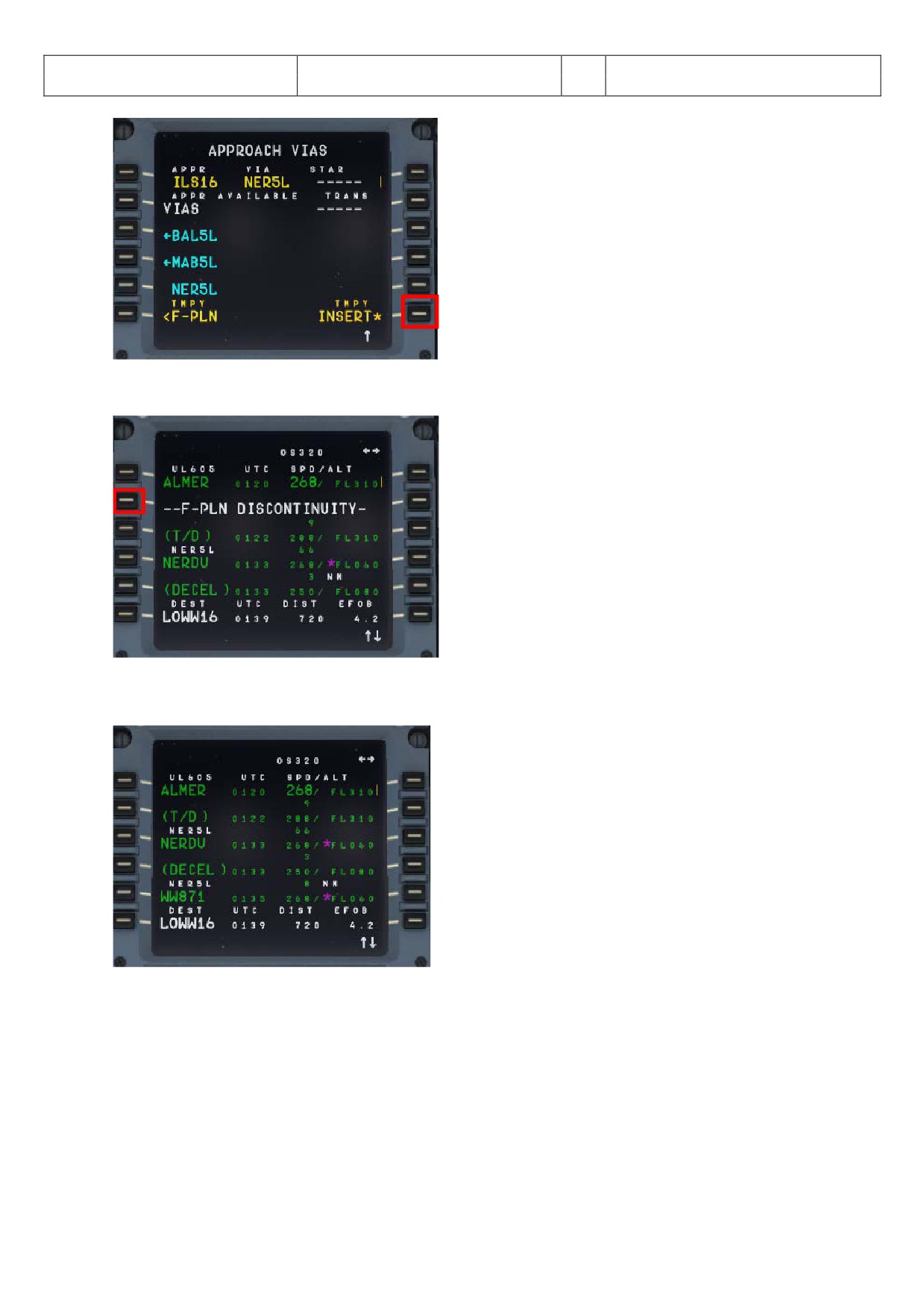
Aerosoft
The Airbus A318/319/320/321 in FSX
Vol
06-01-09 Page 110
Airbus A318/319/320/321
Step-By-Step Tutorial
6
25 October 2015
Picture 142: LOWW ARRIVAL
Delete the F-PLAN DISCONTINUITY
Picture 143: Active F-PLAN (before CLR)
Final active flightplan EDDF (primary departure) - LOWW (alternate destination)
Picture 144: Active F-PLAN EDDF - LOWW
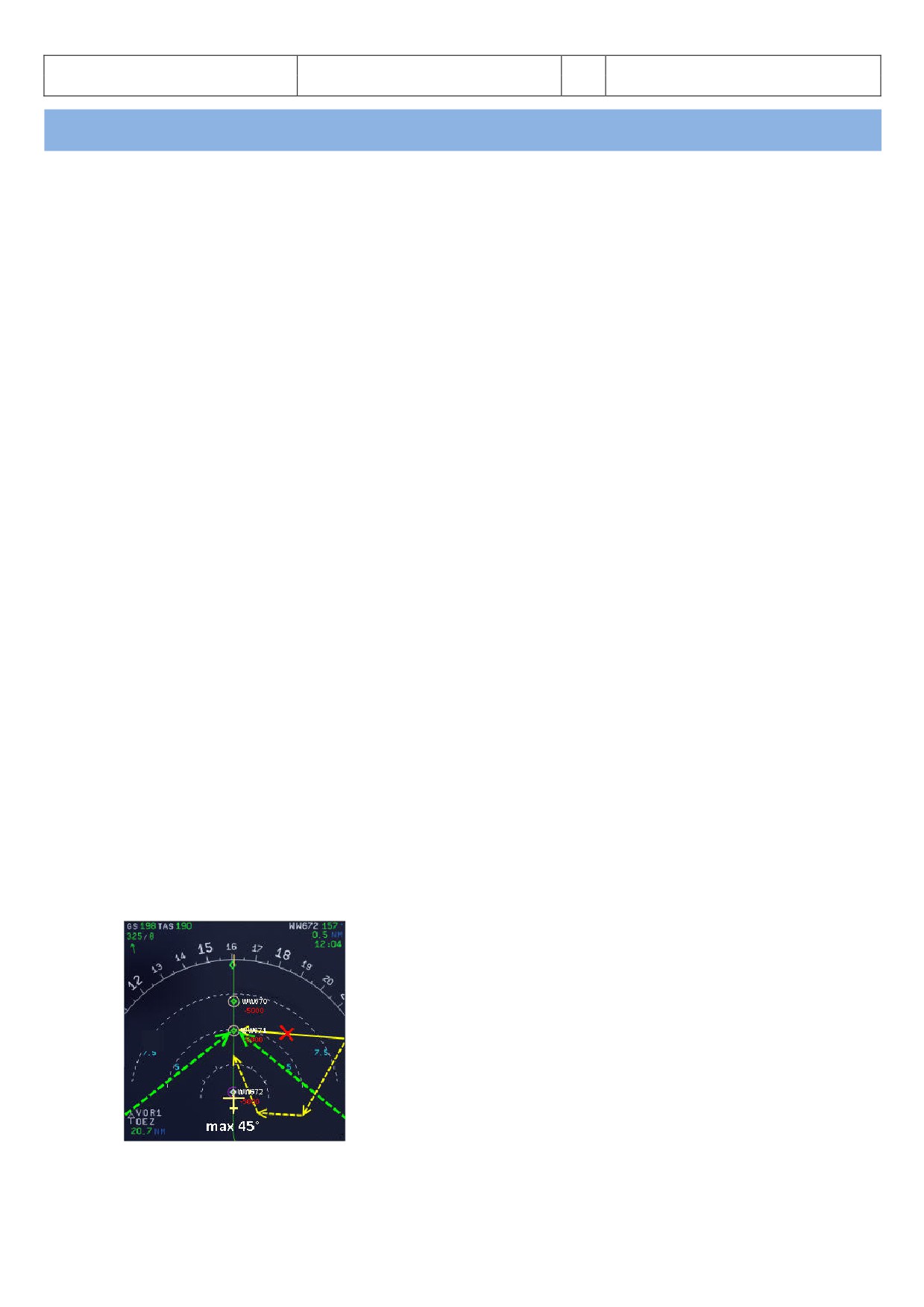
Aerosoft
The Airbus A318/319/320/321 in FSX
Vol
06-01-09 Page 111
Airbus A318/319/320/321
Step-By-Step Tutorial
6
25 October 2015
10.
Tips and Tricks:
10.1
Adjusting views:
If you want to adjust one of the various available views first open it e. g. it becomes the active window. Then the
following key combinations are available:
• CTRL + Return
- Forward
• CTRL + Backspace
- Backwards
• CTRL + SHIFT + Return
- Left
• CTRL + SHIFT + Backspace
- Righ
• SHIFT + Return
- Higher
• SHIFT + Backspace
- Lower
• SPACE BAR + Mouse wheel
- Zoom in or out
• SPACE BAR + Mouse
- Changing the view angle
10.2
Keeping / saving adjusted views
After you adjusted the views (using the aforementioned key combinations) during the whole flight e. g. until you
close the FSX respectively change to another aircraft, those adjustments will be kept.
10.3
Working with real Flight Plans:
On the Internet there are several pages where “real” flight plans (like the one we used in this tutorial) are
available. Two of the addresses are
On those pages you will find a lot of plans but you should know the airport codes (like in our example EDDF for
Frankfurt or LOWW for Vienna). But those codes can be found also using the Microsoft FS Flight Planner. Those
plans like in our example can be used for all Aerosoft Airbus A318/319/320/321 types.
10.4
„Capturing“ the ILS-Glide Path:
Sometimes the chosen flight path reaches the last waypoint before capturing the ILS glide path (13OEZ) in a way
that the angle would be too big to capture it. The ideal angle should not be greater than 45 degrees and in such
cases you then should fly a manually set course (see yellow dotted line) to catch the glide path the right way.
In the following example - Picture 65: Angle „capturing“ a glide path - (before we reach WW671) please press
LOC so that the lateral glide path will be caught. After catching the lateral glide and the vertical glide path starts
moving (please see Picture 60) press APPR (to also catch the vertical glide path) and prepare for a smooth
landing.
Picture 145: Angle „capturing“ a glide path
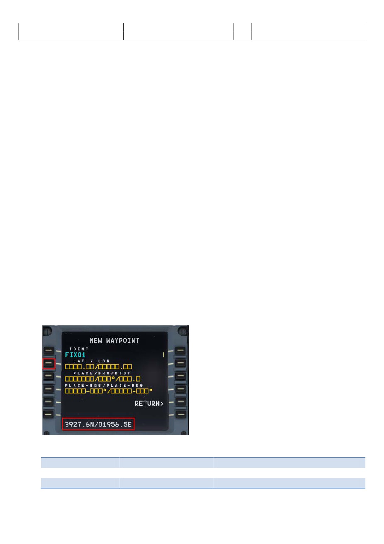
Aerosoft
The Airbus A318/319/320/321 in FSX
Vol
06-01-09 Page 112
Airbus A318/319/320/321
Step-By-Step Tutorial
6
25 October 2015
10.5
Transfer this document to the iPad
If you do not want to print out this document (and have an iPad in your possession), another way to have it
always available during the flight is: Transfer it to your iPad. The easiest way to do this is:
• Download the ACROBAT Reader for the iPad from the Apple Store (it is for free) and install it on your
iPad. An ACROBAT icon will be created on your iPad.
• Connect / synchronize your iPad with the PC using iTunes.
• In iTunes select the iPad and change to the APPS page.
• At the bottom of the page you will see the ACROBAT icon and the list of documents which are already
available in ACROBAT. Use “ADD” to select this document (saved in your FSX folder under Aerosoft /
Airbus A318_A319 (or Airbus A320_321) / Documentation) and it will be transferred to your iPad.
• Open ACROBAT and select “Documents”. Now this tutorial should be available and can be opened and
used on your iPad.
10.6
MCDU (left only) on an external device
To use the web interface start AirbusXConnectExtended.exe that is located in FSX Main Folder\Aerosoft\Airbus
A318_A319 (or Airbus A320_321). You can do this before starting FSX or later. It will open a small window
showing you the ip address and the port, something like this: 123.123.123.123:4040. You can enter this address
into the address bar of the browser on any device that is connected to the same network. It will open showing
the MCDU and you can use it as you would in the aircraft.
10.7
Use of the Procedure and Checklist
After using this tutorial and flying the Aerosoft Airbus A318/319/320 or 321 several times you will not need the
explanations anymore. Then you can just use the complete procedure and checklist and fly the Airbus as a pilot
and nearly as in the real life. Just the procedure- and checklist you will find as Appendix 11.
10.8
Manually entered waypoints
It is possible to manually enter waypoints (FIXES) which are not available in the Navigation DB. If you enter a
waypoint which is not available in the DB a new MCDU window opens. Enter the values for latitude and
longitude into the scratchpad and then push LSK 2L.
Picture 146: Manually entered waypoints
The following formats are possible to enter:
54.14.19N 002.58.51W
= 5414.2N/00258.5W
54.235333,-2.971667
= 54.2N/2.9W
+ LAT=N/-LAT=S/+LONG=E/-LONG=W
n54 14.2 w002 58.5
= N5414.2/W00258.5
Aerosoft
The Airbus A318/319/320/321 in FSX
Vol
06-01-09 Page 113
Airbus A318/319/320/321
Step-By-Step Tutorial
6
25 October 2015
11. Appendix / Glossary:
Abbreviation
Description
ABV
Above (TCAS)
ADF
Automatic Directon Finder
A/C
Aircraft
AGL
Above Ground Level
A.FLOOR
Alpha Floor
AMP
Audio Management Panel
ANN
Annunciator
A/THR
Autothrust
AC
Air Conditioning
ADIRS
Air Data Inertial Reference System
AIRAC
Aeronautical Information Circular
ALT
Altitude
AP
Autopilot
APPR
Approach (Key on FCU)
APU
Auxiliary Power Unit
ATC
Air Traffic Control
BLOCK
Fuel Weight (kg)
BLW
Below (TCAS)
BRG
Bearing
CFM
Engine Manufacturer GE + SNECMA
CL or CLB
Climb
CLR
CLEAR (Key on MCDU Keyboard)
CO RTE
Company Route
CRZ FL
Cruise Flight Level
DES
Descent
DH
Decision Height
DIR
Direct
DME
Distance Measuring Equipment
ECAM
Electronic Centralized Aircraft Monitoring
EFIS
Electronic Flight Instrument System
EFOB
Estimated Fuel On Board
ELAC
Elevator and Aileron Computer
ENG
Engine
ETD
Estimated Time of Departure
E/WD
Engine/Warning Display
EXPED
Expedite (FCU Key)
EXT PWR
External Power
EXT LT
External Lights
FAC
Flight Augmentation Computer
FADEC
Full Authority Digital Engine Control
FCU
Flight Control Unit
FD
Flight Director
FDR
Flight Data Recorder
FF
Fuel Flow
FL
Flight Level
FLEX
Flexible
FLX/MCT
Flexible/Maximum Continuous Thrust
FMA
Flight Mode Annunciator
FMGC
Flight Management and Guidance Computer
FO
First Officer
FOB
Fuel On Board
FPA
Flight Path Angle
F-PLAN
Flight Plan (MCDU Page)
Aerosoft
The Airbus A318/319/320/321 in FSX
Vol
06-01-09 Page 114
Airbus A318/319/320/321
Step-By-Step Tutorial
6
25 October 2015
FQ
Fuel Quantity
GPU
Ground Power Unit
GPWS
Ground Proximity Warning System
GS
Glide Slope
GW
Gross Weight
HDG
Heading
hPa
Air Pressure Unit of Measurement (hector Pascal)
IAE
Int. Aero Engines = Engine Manufacturer RR, P&E, MTU + JAEC
ILS
Instrument Landing System
In Hg
Air Pressure Unit of Measurement (Inch Mercury)
INIT
Initiation (MCDU Page)
KG
Kilogram
IRS
Inertial Reference System
L/G
Landing Gear
LK
Lock
LOC
ILS Localizer
LSK
Line Select Key
MCDU
Multifunction Control and Display Unit
MDA
Minimum Descent Altitude
MKR
Marker
N/W
Nose Wheel
ND
Navigation Display
NDB (ADF)
Nondirectional Beacon (Automatic Direction Finder)
NM
Nautical Miles
PERF
Performance (MCDU Page)
PFD
Primary Flight Display
PPU
Power Push Unit
PROG
Progress (MCDU Page)
QNH
Barometric Pressure Reported By A Station
PSI
Pounds Per Square Inch
PTU
Power Transfer Unit
RAD/NV
Radio/Navigation (MCDU Page)
RAAS
Runway Awareness and Advisory System
RMP
Radio Management Panel
RTO
Rejected Takeoff
RWY
Runway
SD
System Display
SEC
Spoiler and Elevator Computer
SID
Standard Instrument Departure
SRS
Speed Reference System
STAR
Standard Terminal Arrival Route
STDBY
Standby (TCAS)
SW
Switch
TA
Traffic Advisory (TCAS)
TA/RA
Traffic Advisory & Resolution Advisory
TAS
True Airspeed
T/C
Top of Climb
TCAS
Traffic Alert and Collision Avoidance System
T/D
Top of Descent
TERR
Terrain Proximity Alert (GPWS)
THR
Thrust
THR RED
Thrust Reduction
THRT
TCAS Threat
THS
Trimmable Horizontal Stabilizer
TOGA
Takeoff Go-Around
TOW
Takeoff Weight
TRANS
Transition
TRK
Track
UTC
Universal Coordinated Time
V1
Speed at which takeoff cannot be aborted
Aerosoft
The Airbus A318/319/320/321 in FSX
Vol
06-01-09 Page 115
Airbus A318/319/320/321
Step-By-Step Tutorial
6
25 October 2015
V2
Minimum Takeoff Safety Speed
V/S
Vertical Speed
Vfe
Maximum Flap Extended Speed
VHF
Very High Frequency
Vls
Minimum Safe Speed
Vmax
Maximum Operating Speed In Current Condition
Vmo/Mmo
Maximum Operating Limit Speed
VOR
Very High Frequency Omnirange Station
Vr
Rotation Speed
XFR
Transfer
ZFW
Zero Fuel Weight
ZFWCG
Zero Fuel Weight Centre of Gravity
Aerosoft
The Airbus A318/319/320/321 in FSX
Vol
06-01-09 Page 116
Airbus A318/319/320/321
Step-By-Step Tutorial
6
25 October 2015
12. Checklists and Procedures A 319 CFM
12.1
Basic Preparation Procedure (aircraft in COLD DARK state)
BASIC PREPARATION PROCEDURE
PANEL
ACTION
NO.
REMARK
TYP
PART (Name)
PART (No.)
PF (PILOT FLYING)
PM (PILOT MONITORING)
1
FUEL PLANNER ADV. METH.
PAX-, CARGO- and FUEL LOAD
SET and GEN. LOADSHEET
Please see chapter 4.1 for details
2
MCDU R
MAIN MENU
ACFT STATE
COLD DARK = LSKL1
PUSH
Should already been done
3
OVERHEAD
ELEC
3
BAT 1 + 2 (Batteries)
ON (BOTH)
Should already been done
4
OVERHEAD
ELEC
3
EXT POWER
ON
5
OVERHEAD
EXT. LIGHTS
9
EXT. LIGHTS (= Nav Lights)
ON
6
MAIN PANEL
PFD LIGHT
8
SWITCH
ON
7
MAIN PANEL
ND LIGHT
8
SWITCH
ON
8
ECAM
ECAM LIGHTS
4
SWITCH UPPER and LOWER
ON
9
PEDESTAL
INT. LIGHT
3
OVHD INTEG LT
ON
10
MCDU R
OPTIONS
SOUND
Cabin & Flight Crew, ATC
[ON] or [OFF]
As required - Color switches to green
11
MCDU R
OPTIONS
VIEWS
Panel & Wing View Bars and others
[ON] or [OFF]
As required - Color switches to green
12
MCDU R
OPTIONS
CHECKLISTS
CHECKL and COPILOT
ON (BOTH)
13
MCDU R
OPTIONS
CHECKLISTS
INFOBAR
ON
14
MCDU R
OPTIONS
CHECKLISTS
Various LIMITERS ( APP & 250 KNOTS) & ILS
[ON] or [OFF]
As required - Color switches to green
15
MCDU R
OPTIONS
CHECKLISTS
AES
[ON] or [OFF]
As required - Color switches to green
16
MCDU R
LOAD/FUEL
INIT LOADSHEET or manually enter data
16
MCDU R
LOAD/FUEL
LOAD to PLANE
LOAD INSTANT or separately
12.2
Cockpit Preparation
COCKPIT PREPARATION
PANEL
ACTION
NO.
REMARK
TYP
PART (Name)
PART (No.)
PF (PILOT FLYING)
PM (PILOT MONITORING)
TA
17
MCDU
MAIN MENU
CHECKLIST
A = PUSH LSK3L
PUSH
Start Checklist / Co-Pilot - if selected
18
OVERHEAD
ELEC
3
BAT 1 + 2 (Batteries)
CHECK ON (BOTH)
Cop
19
OVERHEAD
ELEC
6
EXT PWR (External Power)
ON
CoP
(if available - see MCDU MENU / DOORS)
20
OVERHEAD
EXT. LIGHTS
9
NAV. LIGHTS
CHECK ON
CoP
21
PEDESTAL
ENG
5
ENG MASTER 1 + 2
CHECK OFF
CoP
TA
22
PEDESTAL
ENG
5
ENG MODE SEL
CHECK NORM
CoP
TA
23
ECAM
LAND GEAR
2
LANDING GEAR LEVER
CHECK DOWN
CoP
24
PEDESTAL
P. BRAKE
7
PARKING BRAKE
CHECKED = OFF
CoP
TA
25
PEDESTAL
FLAPS
8
FLAPS LEVER
CHECK POSITION = 0
CoP
26
PEDESTAL
SP. BRAKE
6
SPEED BREAK LEVER
CHECK RETR. / DISARMED
CoP
27
PEDESTAL
THR LEVER
4
THRUST LEVERS
CHECK IDLE
TA
28
PEDESTAL
RADIO
1
TRANSPONDER MODE
CHECKED STANDBY
29
PEDESTAL
RADIO
1
RADIO CONTROL PANEL
ON
CoP
30
ECAM
ECAM
5
ECAM RECALL (RCL) BUTTON
PRESS
CoP
TA
31
MAIN PANEL
ANTI SKID
10
ANTI SKID
CHECK ON
CoP
TA
32
MAIN PANEL
EFIS
3
FLIGHT DIRECTOR
CHECK ON
CoP
33
OVERHEAD
SIGNS
12
EMERGENCY LIGHTS
ARM
CoP
TA
34
OVERHEAD
SIGNS
12
NO SMOKING SIGNS
ON
CoP
TA
35
OVERHEAD
SIGNS
8
WING & ENGINE ANTI ICE
CHECK OFF
Cop
36
OVERHEAD
PR.WI. HEAT
13
PROBE WINDOW HEAT
AUTO/OFF
37
OVERHEAD
AIR COND.
7
HOTAIR, ENG. BLEED L+R, PACKS L+R
CHECK ON
Cop
TA
(no white signs)
38
OVERHEAD
VENTILATION
14
BLOWER, EXTRACT, CAB. FANS
CHECK ON
TA
(no white signs - INOP not animated)
39
OVERHEAD
ELECTRIC
5
ENG. GENERATOR L+R
CHECK ON = FAULT
Cop
40
OVERHEAD
ELETRIC
5
APU GENERATOR
CHECK ON
(only if EXT. POWER is ON)
41
OVERHEAD
FUEL
2
ALL FUEL PUMPS
PRESS
CoP
TA
OFF should disappear
42
OVERHEAD
FUEL
2
ALL FUEL PUMPS = ON
CHECK
43
OVERHEAD
HYDRAULICS
1
ACCU BREAK PRESS: ELEC. PUMP
(ON)
See explanation
44
OVERHEAD
GPWS
15
GPWS: ALL SWITCHES
CHECK ON
Cop
(no white signs)
45
OVERHEAD
EFCS
16
EFCS: ALL SWITCHES
CHECK ON
Cop
(no white signs)
46
OVERHEAD
ADIRS
17
ADIRS (3x)
ON
CoP
TA
47
COCKPIT
EM.EQUIPMENT
ALL EQUIPEMT AVAILABLE AND OK
CHECK ON
Checklist complete
48
PEDESTAL
RADIO
1
SET FREQUENCIES
SET
If ATC is used
49
PEDESTAL
RADIO
1
ATC CLEARANCE
OBTAIN
If ATC is used
Aerosoft
The Airbus A318/319/320/321 in FSX
Vol
06-01-09 Page 117
Airbus A318/319/320/321
Step-By-Step Tutorial
6
25 October 2015
12.3
FMGS / MCDU - Data Insertion
COCKPIT PREPARATION - FMGS/MCDU DATA INSERTION
PANEL
ACTION
NO.
PART (Name)
PART
REMARK
TYP
PF (PILOT FLYING)
PM (PILOT MONITORING)
(No.)
50
MCDU
INIT 1
DEP and DEST AIRPORT
ENTER
LOWI/LFMN
51
MCDU
INIT 1
ALIGN IRS
PRESS
52
MCDU
INIT 1
FLT NBR (Flight Number)
ENTER
Par example =LH319
53
MCDU
INIT 1
COST INDEX
ENTER
40
54
MCDU
INIT 1
CRZ FL (Cruise Flight Level)
ENTER
=310 (31.000 feet)
55
MCDU
F-PLAN
FLIGHTPLAN
ENTER
Speeds and altitudes are now calculated
56
MCDU
RAD NAV
ENTER ADF1 FREQUENCY
ENTER
RTT
57
MCDU
INIT 2
BLOCK
ENTER
6.8
58
MCDU
INIT 2
ZFWCG/ZFW
CHECK
25.0/49.5 - speeds and altitude are calculated
59
MCDU
PERF-TO
FLAPS / THS
ENTER
2/
60
MCDU
PERF-TO
FLEX TO TEMP
CHECK
61
MCDU
PERF-TO
V1, VR and V2
CHECK
89/120/124
62
MCDU
PERF-CLIMB
DATA
CHECK
63
MCDU
PERF-CZR
DATA
CHECK
64
MCDU
PERF-DES/APPR
DATA
CHECK
65
MCDU
PERF-GO ARD
DATA
CHECK
12.4
Cockpit Preparation - Part 2
COCKPIT PREPARATION - Part 2
PANEL
ACTION
NO.
REMARK
TYP
PART (Name)
PART (No.)
PF (PILOT FLYING)
PM (PILOT MONITORING)
66
EFIS
FD / ILS
3
Button: LS
OFF
67
EFIS
ND MOD/RGE
5 & 6
ND mode and range
SET
Mode: ARC / Range 10
68
EFIS
ADF/VOR
7
VOR / ADF select
AS REQUIRED
69
FCU
ALTITUDE
3
First Altitude
SET TO 12.000 Feet
>than THR RED altitude
70
FCU
FCU
1 to 4
DASH-BALL-DASH-BALL-ALT-BALL-DASH
CHECK
71
ECAM
ECAM
1
STATUS
CHECK
72
PEDESTAL
RADIO
1
ATC - FREQUNCY
SET
If ATC is used
73
PEDESTAL
RADIO
1
ATC CLEARANCE
OBTAIN
If ATC is used
74
GLARESHIELD
ND-DISPL.
2
IRS ALIGN
CHECK
75
MCDU
F-PLAN
F-PLAN PAGE
SET
12.5
Before Pushback and Start
BEFORE PUSHBACK OR START
PANEL
ACTION
NO.
REMARK
TYP
PART (Name)
PART (No.)
PF (PILOT FLYING)
PM (PILOT MONITORING)
76
MCDUw
MAIN MENU
ACFT DOORS
CLOSE ALL DOORS
PUSH
Start Checklist / Co-Pilot - if selected
77
MCDU R
MAIN MENU
ACFT DOORS
ALL WINDOWS AND DOORS CLOSED
CHECK
CoP
78
OVERHEAD
APU
10
APU MASTER and START
ON
CoP
START= available 10 sec after MASTER
79
OVERHEAD
APU
10
APU BLEED = ON
ON
CoP
80
MCDU
ELEC
6
EXT PWR
OFF
CoP
81
OVERHEAD
SIGNS
12
SEAT BELT SIGNS / NO SMOKING = ON
ON
CoP
For Seat Belts also AUTO is OK
82
PEDESTAL
THR LEVER
4
LEVERS
CHECK IDLE
83
PEDESTAL
P. BRAKE
7
PARKING BRAKE
SET to ON
CoP
FSX: CTRL + . (period)
84
MCDU2
MAIN MENU
GND SERV.
TRAFFIC CONES
REMOVE
CoP
85
MCDU2
MAIN MENU
GND SERV.
WHEEL CHOCKS
REMOVE
CoP
86
EFIS
AP SETTING
2
BARO REF
SET / X CHECK (Read out)
CoP
87
OVERHEAD
EXT. LIGHTS
9
BEACON
ON
CoP
Checklist complete
Aerosoft
The Airbus A318/319/320/321 in FSX
Vol
06-01-09 Page 118
Airbus A318/319/320/321
Step-By-Step Tutorial
6
25 October 2015
12.6
Engine Start
12.6.1 Engine Start with Pushback
ENGINE START - with pushback
PANEL
ACTION
NO.
REMARK
TYP
PART (Name)
PART (No.)
PF (PILOT FLYING)
PM (PILOT MONITORING)
88
MCDU
MAIN MENU
CHECKLIST
SELECT: “START WITH PUSH” = LSK5L
Starts next Checklist / Co-Pilot - if selected
89
MCDU right
SELECT TAXIWAX DIST and PB DIRECTION
SET
90
MCDU right
START PUSHBACK
START
91
„Flight Deck to Ground“
GROUND: „Go ahead“
92
„We have ATC clearance“
GROUND: „Roger“
93
„Confirm ground equipment = clear”
GROUND: “Clear”
94
“Starting pushback”
GROUND: “Roger”
95
PEDESTAL
P. BRAKE
7
PARKING BRAKE = OFF
SET to OFF
FSX: . (period)
96
GROUND: “OK. Starting Pushback”
97
PEDESTAL
ENGINE
5
ENG MODE SEL
IGN START
98
PEDESTAL
ENGINE
5
MASTER SW 2
ON
99
MAIN PANEL
E/WD
5a
No. 2 RUNNING UP
CHECK
100
PEDESTAL
ENGINE
5
MASTER SW 1
ON
Engine 2 N1 > 20%
101
MAIN PANEL
E/WD
5a
No. 1 RUNNING UP
CHECK
102
When in Position: Stop Pushback
STOP (SHIFT + P)
103
GROUND: „Pushback complete”
104
PEDESTAL
P. BRAKE
7
PARKING BRAKE
ON
FSX: CRTL +.(period)
105
GROUND: “Have a good flight” - CL complete
12.6.2 Engine Start without Pushback
ENGINE START
PANEL
ACTION
NO.
REMARK
TYP
PART (Name)
PART (No.)
PF (PILOT FLYING)
PM (PILOT MONITORING)
106
MCDU
MAIN MENU
CHECKLIST
SELECT: “START” = LSK6L
Starts next Checklist / Co-Pilot - if selected
107
„Flight Deck to Ground“
GROUND: „Go ahead“
108
„We have ATC clearance“
GROUND: „Roger“
109
„Confirm ground equipment = clear”
GROUND: “Clear”
110
„Starting engines“
GROUND: „Roger“
111
PEDESTAL
ENGINE
5
ENG MODE SEL
IGN START
112
PEDESTAL
ENGINE
5
MASTER SW 2
ON
113
MAIN PANEL
E/WD
5a
No. 2 RUNNING UP
CHECK
114
PEDESTAL
ENGINE
5
MASTER SW 1
ON
Engine 2 N1 > 20%
115
MAIN PANEL
E/WD
5a
No. 1 RUNNING UP
CHECK
116
“Both Engines running”
GROUND: „Roger“
117
GROUND: “Have a good flight” - CL complete
12.7
After Engine Start
AFTER ENGINE START
PANEL
ACTION
NO.
REMARK
TYP
PART (Name)
PART (No.)
PF (PILOT FLYING)
PM (PILOT MONITORING)
118
ENGINE 1 & 2 are running for 15 sec
Start Checklist / Co-Pilot - if selected
119
PEDESTAL
ENGINE
5
ENG MODE SEL
NORM
CoP
120
OVERHEAD
APU
10
APU BLEED
OFF
CoP
121
OVERHEAD
APU
10
APU MASTER SW
OFF
CoP
122
PEDESTAL
SPEED-BR.
6
GROUND SPOILERS
ARM
CoP
Mouse click: right
123
PEDESTAL
RUDDER
4
RUDDER TRIM
SET to 0 degree
CoP
124
PEDESTAL
PITCH
4
PITCH TRIM
SET to THS Value
125
AILERON, ELEVATOR and RUDDER
CHECK ALL 6 POSITIONS
126
PEDESTAL
FLAPS
8
FLAPS
SET to 2
CoP
FSX: F7
127
OVERHEAD
ANTI-ICE
8
ENG ANTI ICE (1 &2)
ON / OFF
128
OVERHEAD
ANTI-ICE
8
WING ANTI ICE
ON / OFF
129
ECAM
ECAM
1
ECAM STATUS
CHECK
130
ECAM
ECAM
1
ECAM DOOR PAGE
CHECK
CoP
131
HAND SIGNAL RECEIVED
Checklist complete
Aerosoft
The Airbus A318/319/320/321 in FSX
Vol
06-01-09 Page 119
Airbus A318/319/320/321
Step-By-Step Tutorial
6
25 October 2015
12.8
TAXI
TAXI
PANEL
ACTION
NO.
REMARK
TYP
PART (Name)
PART (No.)
PF (PILOT FLYING)
PM (PILOT MONITORING)
132
PEDESTAL
RADIO
1
TAXI CLEARENCE
OBTAINED
If ATC is used
133
PEDESTAL
P. BRAKE
7
PARKING BRAKE
OFF
FSX: . (period)
134
GS> 10 Knots
Start Checklist / Co-Pilot - if selected
135
OVERHEAD
EXT. LIGHTS
9
NOSE LIGHT
TAXI
CoP
136
PEDESTAL
THR LEVER
4
LEVERS
AS REQUIRED
137
PRESS BRAKES to listen for PM CALL
PRESS PEDAL / RELEASE
138
MAIN PANEL
AUTO BRAKE
6
SET TO
MAX
CoP
139
MCDU
TAKEOFF DATA
REVIEW
CoP
140
FCU
HDG / ALT
2 & 3
FCU HDG/ALT = DASH-BALL-DASH-BALL
SET or CHECK
IF ALT NOT SET CoP sets it to 7000ft
141
ALL DISPLAYS ARE ON
CHECK
142
ECAM
PANEL
5
TO CONFIG
PRESS
CoP
143
MAIN PANEL
E/WD
5a
TO MEMO
CHECK NO BLUE
CoP
144
PEDESTAL
WXR
11
SET system to 1 (ON) and knob to WX-T
SET
CoP
Checklist complete
145
EFIS
FD / ILS
3
FD
CHECK ON
146
PEDESTAL
TRANSPOND.
9
ATC CODE
CONFIRM / SET
If ATC is used
12.9
Before Takeoff
BEFORE TAKEOFF
PANEL
ACTION
NO.
REMARK
TYP
PART (Name)
PART (No.)
PF (PILOT FLYING)
PM (PILOT MONITORING)
147
INFORMATION TO CABIN CREW
“Please prepare for Takeoff”
148
OVERHEAD
EXT. LIGHTS
9
TAXI TO RUNWAY HOLDING POINT
Start Checklist / Co-Pilot please see below
149
ECAM
WHEEL PAGE
1
BRAKE TEMP = below 150
CHECK
Cop
CoP set Brake Fans On if Brake Temp > 150
150
MAIN PANEL
BRAKE FAN
11
BRAKE FANS
OFF
Cop
151
PEDESTAL
ENGINE
5
ENG MODE SEL = NORMAL
CHECK
152
PEDESTAL
TCAS
10
TCAS TA/RA plus TILT ABOVE
SET
CoP
153
OVERHEAD
EXT. LIGHTS
9
EXT. LIGHTS
SET
CoP
Strobes, Land. and Nose Lights
154
PF SLIDING TABLE
STOWED
Cop
Checklist complete
155
PEDESTAL
WXR
11
TILT: UP and select 4 degrees up
SET
156
MAIN PANEL
N/SKID NW
10
A/SKID & NW STRG
CHECK = ON
157
PEDESTAL
RADIO
1
TAKEOFF / LINE UP CLEAR
OBTAIN
If ATC is used
158
PEDESTAL
RADIO
1
ATC (if no AUTO position)
ON
If ATC is used
12.10 Takeoff (Part 1)
TAKEOFF - Part 1
PANEL
ACTION
NO
REMARK
TYP
PART (Name)
PART (No.)
PF (PILOT FLYING)
PM (PILOT MONITORING)
158
PEDESTAL
THR LEVER
4
SET LEVERS TO
MAN TOGA
159
GLARESHIELD
CHRONO
7
CHRONO
START
CoP
Push upper right button
12.11 Takeoff Abort
ABORT TAKEOFF
PANEL
ACTION
REMARK
TYP
PART (Name)
PART (No.)
PF (PILOT FLYING)
PM (PILOT MONITORING)
PEDESTAL
THR LEVER
6
THRUST LEVERS
IDLE
FSX: F1
PEDESTAL
THR LEVER
6
REV
MAX
FSX: F2 (hold some time)
PEDESTAL
THR LEVER
6
REV
OFF
At 70 knots = FSX: 1
MAIN PANEL
BRAKES
6
AUTOBRAKES
OFF
At 35 knots
PEDESTAL
FLAPS
10
FLAPS
UP
>12 knots
PEDESTAL
SPEED-BR.
8
GRD SPOILERS
DISARM
>12 knots
OVERHEAD
EXT. LIGHTS
9
STROBES
OFF
>12 knots
OVERHEAD
EXT. LIGHTS
9
LANDING LIGHTS
OFF
>12 knots
PEDESTAL
TCAS
10
TCAS
STANBY
>12 knots
PEDESTAL
FLAPS
10
FLAPS
TO POSITION
PEDESTAL
SPEED-BR.
8
GRD SPOILERS
ARM
Please follow procedure again from # 128
Aerosoft
The Airbus A318/319/320/321 in FSX
Vol
06-01-09 Page 120
Airbus A318/319/320/321
Step-By-Step Tutorial
6
25 October 2015
12.12 Takeoff (Part 2)
TAKEOFF - Part 2
PANEL
ACTION
NO.
REMARK
TYP
PART (Name)
PART (No.)
PF (PILOT FLYING)
PM (PILOT MONITORING)
160
Takeoff thrust is set
Start Checklist / Co-Pilot - if selected
161
“Takeoff”
162
“MAN” „TOGA“ and „SRS“
„ Power set”
163
“100 Knots”
At 100
164
“Checked”
165
“V1”
At GS = V1
166
“Rotate”
At GS = VR
167
“Positive climb”
Radio Alt >50 ft, VS > 100 ft/min
168
MAIN PANEL
GEAR
7
“Gear up”
GEAR UP
CoP
FSX: G
169
PEDESTAL
SPEED-BR.
6
GROUND SPOILERS
DISARM
CoP
FSX: /
170
MAIN PANEL
GEAR
7
GEAR STOWED
“Gear is up , lights off”
Radio Alt >50 ft, VS > 100 ft/min
171
At Thrust Red. / Acceleration Alt.
172
PEDESTAL
THR LEVER
4
SET LEVERS TO
"CLIMB THRUST"
Blinking announcement in FMA
173
FCU
AP
5
AUTOPILOT
"AUTOPILOT ON"
174
At “Green Dot Speed” / “S-Speed”
175
PEDESTAL
FLAPS
8
“Flaps zero”
SELECT
CoP
FSX: F6
176
“Flaps zero”
Checklist complete
177
FCU
ALTITUDE
3
Cruise Altitude
SET TO 31.000 feet
12.13 After Takeoff
TAKEOFF - Part 2
NO.
PANEL
ACTION
REMARK
178
PEDESTAL
WXR
11
TILT: DOWN
SET
179
EFIS
INFOR.
4
EFIS OPTION
ARPT
180
PEDESTAL
RADIO
1
RADIO NAV
CHECK
181
PEDESTAL
ECAM
1
ECAM MENU
REVIEW
182
MCDU
PROG
OPT / MAX ALTITUDE
CHECK
183
FLAPS UP and RETRACTED
Start Checklist / Co-Pilot - if selected
184
PEDESTAL
ENGINE
5
ENG MODE SEL = NORMAL
CHECK
Cop
185
PEDESTAL
SPEED-BR.
6
GROUND SPOILERS
DISARMED
CoP
FSX: /
186
PEDESTAL
FLAPS
8
FLAPS UP and RETRACTED
CHECK
CoP
FSX: F6
187
ECAM
GEAR
2
GEAR IS UP and STOWED
„Gear is up, Lights off“
CoP
188
OVERHEAD
EXT. LIGHTS
9
RUNWAY / NOSE = OFF
OFF
CoP
189
OVERHEAD
AIR COND
7
1 st and 2ND PACK are ON
CHECK
Cop
190
OVERHEAD
ANTI-ICE
8
ANTI ICE (1 &2)
AS REQUIRED
=OFF
191
PEDESTAL
TCAS
10
TCAS = TA/RA and TILT = ABV or N
CHECK and set to ABV
192
EFIS
A PRESSURE
2
BARO REF
X-CHECK (Read out)
Checklist complete
12.14 Climb
CLIMB
PANEL
ACTION
NO.
REMARK
TYP
PART (Name)
PART (No.)
PF (PILOT FLYING)
PM (PILOT MONITORING)
193
CLIMB CHECKLIST
Start Checklist / Co-Pilot - if selected
194
At 10.000 feet
195
“Passing 10.000”
196
OVERHEAD
EXT. LIGHTS
9
LANDING LIGHTS
LIGHTS OFF
CoP
197
FCU
ALTITUDE
3
Cruise Altitude
CHECK
=31.000 feet
198
At Transition Altitude
= Checklist completed
199
GL.SH./EFIS
A PRESSURE
13 / 2
BARO REF to STD
SET / X CHECK
CoP
12.15 Cruise
CRUISE
PANEL
ACTION
NO.
REMARK
TYP
PART (Name)
PART (No.)
PF (PILOT FLYING)
PM (PILOT MONITORING)
200
FMA “ALT / ALT CRZ”
Start Checklist / Co-Pilot - if selected
201
PEDESTAL
TCAS
10
TCAS TA or TA/RA plus TILT NORMAL
SET
CoP
202
OVERHEAD
SIGNS
11
SEAT BELTS = OFF or AUTO
CHECK and set to OFF
CoP
203
SLIDING TABLE - COPILOT
EXTENDED
CoP
Procedure complete
204
PEDESTAL
ECAM
1
ECAM MEMO / SYS PAGES
REVIEW
205
MCDU
Var.PAGES
FLIGHT PROGRESS
CHECK
206
MCDU
FUEL PRED
FUEL
MONITOR
207
MCDU
PROG
NAV ACCURANCY
CHECK
208
OVERHEAD
AIR COND
7
CABIN TEMP
MONITOR
Aerosoft
The Airbus A318/319/320/321 in FSX
Vol
06-01-09 Page 121
Airbus A318/319/320/321
Step-By-Step Tutorial
6
25 October 2015
12.16 MCDU PERF APPR page
MCDU PERF APPR PAGE
PANEL
ACTION
NO.
REMARK
TYP
PART (Name)
PART (No.)
PF (PILOT FLYING)
PM (PILOT MONITORING)
209
MCDU
PERF
APPR
QNH, TEMP, MAG WIND
ENTER DATA
210
MCDU
PERF
APPR
TRANS ALT
ENTER DATA
= 5000
211
MCDU
PERF
APPR
BARO / RADIO
ENTER DATA
= BARO 210
212
MCDU
PERF
APPR
VAPP
CHECK
213
MCDU
PERF
APPR
LDG CONF
CHECK
12.17 Descent Preparation
DESCENT PREPARATION
PANEL
ACTION
NO.
REMARK
TYP
PART (Name)
PART (No.)
PF (PILOT FLYING)
PM (PILOT MONITORING)
214
1 min after CRZ level has been reached
Start Checklist / Co-Pilot - if selected
215
SEAT BELTS = ON or AUTO
CHECK and set to ON
Cop
216
OVERHEAD
ANTI-ICE
8
ANTI ICE = OFF
CHECK
217
PEDESTAL
RADIO
1
LANDING INFORMATION
RECEIVED
If ATC is used
218
EFIS
A.PRESSURE
2
BARO REF = STANDARD
CHECK
Cop
219
MCDU
PERF.
APPR
AIR PRESSURE ARRIVAL AIRPORT
“Checked” and readout
Cop
QNH= 1013
220
MCDU
PERF.
APPR
DECISION ALTITUDE
“Checked”
Cop
BARO = 210
221
MCDU
PERF.
APPR
LDG CONF (Flaps)
"Checked"
CoP
Checklist complete
12.18 Descent
DESCENT
PANEL
ACTION
NO.
REMARK
TYP
PART (Name)
PART (No.)
PF (PILOT FLYING)
PM (PILOT MONITORING)
222
FCU
ALT
3
INSERT NEW HEIGHT
INSERT
= 4.000
223
FCU
ALT
3
INITIATE DESCENT
PUSH KNOB
224
MAIN PANEL
PFD
1
DESCENT
MONITOR
225
PEDESTAL
SP BRAKES
6
SET
AS REQUIRED
226
Vert. Mode = DES / Desc.Prep.CL = compl.
Starts next Checklist / Co-Pilot - if selected
227
MAIN PANEL
PFD
1
FMA
CHECK
228
PEDESTAL
TCAS
10
TCAS = TILT BELOW
CHECK and SET
CoP
229
At 10.000 feet:
230
OVERHEAD
EXT. LIGHTS
9
LANDING LIGHTS
ON
CoP
231
EFIS
FD / ILS
3
ILS LOCALIZER (LS)
PUSH
CoP
EFIS
232
At Transition Altitude
= 5000
233
EFIS
A PRESSURE
2
BARO REF to actual pressure value
SET / X CHECK
CoP
Checklist complete
12.19 Approach
APPROACH
PANEL
ACTION
NO.
REMARK
TYP
PART (Name)
PART (No.)
PF (PILOT FLYING)
PM (PILOT MONITORING)
234
5 NM before DECEL pseudo waypoint
Starts next Checklist / Co-Pilot - if selected
235
ECAM
ECAM
1
ECAM MESSAGE
CHECK
236
SLIDING TABLE S - STOWED
STOWED
CoP
237
OVERHEAD
SIGNS
11
CABIN SIGNS = ON
CHECK or set to ON
238
MCDU
PROG
NAV ACCURANCY
CHECK
239
EFIS
A.PRESSURE
2
BARO REF CROSS CHECK
SET and Read out
CoP
Checklist complete
240
Initial approach:
241
OVERHEAD
SIGNS
11
SEAT BELTS
CHECK ON
AUTO is also OK
242
PEDESTAL
ENGINE
5
ENG MODE
CHECK NORM
243
Approx. 15 NM from touchdown:
244
MCDU
PROG
NAV ACCURANCY
MONITOR
245
MAIN PANEL
PFD
1
POSITIONING
MONITOR
Aerosoft
The Airbus A318/319/320/321 in FSX
Vol
06-01-09 Page 122
Airbus A318/319/320/321
Step-By-Step Tutorial
6
25 October 2015
12.20 Final
FINAL
PANEL
ACTION
NO.
REMARK
TYP
PART (Name)
PART (No.)
PF (PILOT FLYING)
PM (PILOT MONITORING)
246
Appr. CL has been completed
Starts next Checklist / Co-Pilot - if selected
247
MCDU
PERF
APPR PHASE
ACTIVATE
CoP
248
MAIN PANEL
PFD
1
CALL: LOCALIZER ALIVE
CoP
2499
FCU
APPR
6
APPR
PUSH
250
MAIN PANEL
PFD
1
LOCALIZER CAPTURED
CHECK
241
MAIN PANEL
251
Green Dot Speed
252
PEDESTAL
FLAPS
8
FLAPS 1
SELECT
CoP
FSX: F7
253
S-Speed
254
PEDESTAL
FLAPS
8
FLAP 2
SET
FSX: F7
OPTIONAL
255
Gkidescope becomes alive
256
FCU
AP
5
SECOND AP
ON
257
Glidescope captured
258
MAIN PANEL
PFD
1
G/S CAPTURE
CHECK
259
Rad. Alt. > 2.000 ft = LANDING MEMO
260
MAIN PANEL
EWD
5
LANDING MEMO
CHECK NO BLUE
261
PEDESTAL
FLAPS
8
FLAPS 2
SELECT
CoP
FSX: F7
262
FCU
ALT
4
GO AROUND ALT
SET TO 2.000 FEET
CoP
Just enter - do not push knob
263
MAIN PANEL
GEAR
7
L/G DOWN
SELECT
CoP
FSX: G
264
PEDESTAL
SPEED-BR.
6
GROUND SPOILERS
ARM
CoP
Mouse click: right
265
OVERHEAD
EXT. LIGHTS
9
NOSE LIGHT (if not TAXI) = TO
ON
CoP
266
When L/G down, below REF SPEED
267
PEDESTAL
FLAPS
8
FLAPS 3
SELECT
CoP
FSX: F7
268
Next REF SPEED:
269
PEDESTAL
FLAPS
8
FLAPS FULL
SELECT
CoP
FSX: F7 / Checklist complete
270
FCU
SPD
1
Set speed to VApp
SET
= 126 (MCDU - PERF - APPR page)
271
PEDESTAL
TCAS
10
TCAS
SET TO „TA ONLY“
272
MAIN PANEL
PFD
1
FMA
CHECK
273
MAIN PANEL
PFD
1
LOC CAPTURE
MONITOR
274
ECAM
ECAM
1
ECAM WHEEL PAGE
CHECK
275
FCU
ATHR
7
A/THR
CHECK SPD
276
OVERHEAD
ANTI-ICE
8
WING ANTI ICE
CHECK OFF
12.21 Landing
LANDING
PANEL
ACTION
NO.
REMARK
TYP
PART (Name)
PART (No.)
PF (PILOT FLYING)
PM (PILOT MONITORING)
277
Flaps in Landing Config. (MCDU Settings)
Start next Checklist / Co-Pilot - if selected
278
MAIN PANEL
GEAR
7
LAND. GEAR = FULL EXTRACTED
CHECK
CoP
279
PEDESTAL
SP. BRAKEs
6
GROUND SPOILERS = ARMED
CHECK
CoP
FSX: Right mouse click
280
MAIN PANEL
AUTO BRAKE
6
AUTO BRAKES = MEDIUM
SET
CoP
281
OVERHEAD
EXT. LIGHTS
9
NOSE = TO or TAXI / LANDING L. = ON
CHECK
CoP
282
FCU
ALT
3
GO AROUND ALT
CHECK
CoP
283
AT DECISION ALTITUDE
284
FCU
AP
5
AP
OFF
CoP
FSX: Z
285
At 20 feet:
286
FLARE
PERFORM
287
MAIN PANEL
PDF
1
ALTITUDE
MONITOR
288
PEDESTAL
THR LEVER
4
THRUST LEVERS
IDLE
FSX: F1
289
At touchdown:
290
PEDESTAL
THR LEVER
4
REV
MAX
FSX: F2
291
BRAKES
AS REQUIRED
292
At 70 knots:
293
PEDESTAL
THR LEVER
4
REV
IDLE
FSX: F1
294
At taxi speed:
295
PEDESTAL
THR LEVER
4
REV
STOW
CoP
296
Before 30 knots:
297
MAIN PANEL
AUTO BRAKE
6
AUTOBRK
DISENGAGE
CoP
Checklist complete
298
FCU
AP
5
AP (if applicable)
OFF
CoP
FSX: Z
Aerosoft
The Airbus A318/319/320/321 in FSX
Vol
06-01-09 Page 123
Airbus A318/319/320/321
Step-By-Step Tutorial
6
25 October 2015
12.22 Go Around
GO AROUND
PANEL
ACTION
NO.
REMARK
TYP
PART (Name)
PART (No.)
PF (PILOT FLYING)
PM (PILOT MONITORING)
A
PEDESTAL
THR LEVER
4
GA thrust is set
SET
Start Checklist / Co-Pilot - if selected
B
PEDESTAL
FLAPS
8
“GO AROUND FLAPS”
FLAPS ONE STEP BACK = 3
CoP
FSX: F6
C
“Positive climb”
Radio Alt >50 ft, VS > 100 ft/min
D
MAIN PANEL
GEAR
7
“Gear up”
GEAR UP
CoP
FSX: G
E
MAIN PANEL
GEAR
7
GEAR STOWED
“Gear up , Flaps 3”
F
PEDESTAL
SPEED-BR.
6
GROUND SPOILERS
DISARM
CoP
FSX: /
G
OVERHEAD
EXT. LIGHTS
9
RUNWAY / NOSE = OFF
„Off“
CoP
H
MAIN PANEL
BRAKES
6
AUTOBRAKES
„Off“
CoP
I
At Thrust Red. / Acceleration Alt.
J
PEDESTAL
FLAPS
8
“Flaps 1”
SELECT
CoP
FSX: F6
K
PEDESTAL
THR LEVER
4
SET LEVERS TO
"CLIMB THRUST"
Blinking announcement in FMA
L
FCU
AP
5
AUTOPILOT
ON
M
At “Green Dot Speed” / “S-Speed”
N
PEDESTAL
FLAPS
8
“Flaps up”
SELECT
CoP
FSX: F6
O
“Flaps up”
Checklist complete
P
FCU
AP
5
AUTOPILOT 2
„Off“
CoP
12.23 After Landing
AFTER LANDING
PANEL
ACTION
NO.
REMARK
TYP
PART (Name)
PART (No.)
PF (PILOT FLYING)
PM (PILOT MONITORING)
299
Ground Speed >35 / Dir. to runway > 15 °
Start Checklist / Co-Pilot - if selected
300
GLARESHIELD
CHRONO
7
CHRONO
STOP
Push upper right button
301
OVERHEAD
EXT. LIGHTS
9
NOSE LIGHTS
ON
CoP
302
OVERHEAD
EXT. LIGHTS
9
LANDING LIGHTS
OFF
CoP
303
OVERHEAD
EXT. LIGHTS
9
STROBE LIGHT = OFF or AUTO
If ON = OFF
CoP
304
PEDESTAL
TCAS
10
TCAS MODE SEL
STBY
CoP
305
PEDESTAL
FLAPS
8
FLAPS
RETRACT
CoP
FSX: F6
306
PEDESTAL
ENGINE
5
ENG MODE SEL
NORM
Cop
307
PEDESTAL
WXR
11
WXR: SET system to OFF
SET
Cop
308
EFIS
FD / ILS
3
ILS LOCALIZER (LS)
OFF
CoP
EFIS
309
OVERHEAD
APU
10
APU MASTER and APU START
ON
310
PEDESTAL
SP.BRAKES
6
GRND SPLRS
DISARM
CoP
FSX: /
311
ECAM
WHEEL PAGE
1
BRAKE TEMP all wheels = > 300 degrees
CHECK
Checklist complete
12.24 Parking
PARKING
PANEL
ACTION
NO.
REMARK
TYP
PART (Name)
PART (No.)
PF (PILOT FLYING)
PM (PILOT MONITORING)
312
PEDESTAL
RADIO
1
ATC (if no AUTO position)
STBY / OFF
313
OVERHEAD
ANTI-ICE
8
ANTI ICE (WING and ENGINES 1&2)
CHECK = OFF
314
PEDESTAL
RADIO
1
GROUND CONTACT
ESTABLISH
If ATC is used
315
PEDESTAL
P.BRAKE
7
PARKING BRAKE ON
SET ON
FSX: CTRL + . (period)
316
PEDESTAL
ENGINE
5
ENG MASTER 1 & 2
OFF
Start Checklist / Co-Pilot - if selected
317
MCDU R
GRND SERV
CHOCKS
SET
CoP
318
PEDESTAL
P.BRAKE
7
PARKING BRAKE
OFF
CoP
FSX: . (period)
319
OVERHEAD
SIGNS
11
SEAT BELTS
OFF
CoP
320
OVERHEAD
EXT. LIGHTS
9
BEACON LIGHT
OFF
CoP
321
OVERHEAD
EXT. LIGHTS
9
TAXI LIGHT.
OFF
CoP
322
OVERHEAD
ANTI-ICE
8
WING & ENGINE ANTI ICE = OFF
CHECK
Cop
323
OVERHEAD
FUEL
2
FUEL PUMPS
OFF
CoP
OFF should appear / Checklist complete
324
MCDU R
GRND SERV
CONES
SET
325
MCDU R
GRND SERV
ESTABLISH EXTERNAL POWER
CONNECT
326
OVERHEAD
EXT POWER
6
EXT. POWER = AVAILABLE
SET TO ON
327
OVERHEAD
APU
10
APU MASTER
SET TO OFF
328
MCDU
MENU
ACFT DOORS
DOORS
OPEN (AS REQUIRED)

Aerosoft
The Airbus A318/319/320/321 in FSX
Vol
06-01-09 Page 124
Airbus A318/319/320/321
Step-By-Step Tutorial
6
25 October 2015
12.25 Securing Aircraft
SECURING AIRCRAFT
PANEL
ACTION
NO.
REMARK
TYP
PART (Name)
PART (No.)
PF (PILOT FLYING)
PM (PILOT MONITORING)
329
OVERHEAD
ADIRS
ADIRS (1 + 2 + 3)
OFF
330
OVERHEAD
EXT. LIGHTS
9
NAV. LIGHTS
OFF
331
OVERHEAD
SIGNS
11
NO SMOKING & EMERGENCY LIGHT
OFF
332
MCDU
MENU
ACFT DOORS
DOORS
CLOSE (AS REQUIRED)
333
OVERHEAD
EXT. PWR
6
EXT PWR
AS REQUIRED
334
OVERHEAD
ELEC
5
GEN 1 + 2 (Electric Generators)
PRESS
OFF should appear
335
PEDESTAL
INT. LIGHT
3
INTEG LT
OFF
336
MAIN PANEL
PFD LIGHT
8
SWITCH
OFF
337
MAIN PANEL
ND LIGHT
8
SWITCH
OFF
338
ECAM
DIMMER
4
SWITCH UPPER and LOWER
OFF
339
PEDESTAL
RADIO
1
RADIO CONTROL PANEL
OFF
340
PEDESTAL
TCAS
10
TCAS = STBY
SET
341
OVERHEAD
BATTERIES
4
BAT 1 + 2
OFF
AIRBUS A320/A321
Volume 7
Thrust Lever Setup
Version 02-01-XX
RECORD OF REVISIONS
revision n°
Issue date
Descripton
001
28-Oct-2010
Release

Aerosof
FSX Thrust Lever Setup
Vol
07-01-2
Airbus A320/A321
(only in case you have issues!)
7
28 October 2014
INTRODUCTION
STOP, if you got no problems with the throtles in the Aerosof
Airbus, stop reading and go and fly. This document is really only
needed for people whose setup is none standard.
The throtles of the real Airbus A320 series are not mechanical connected to the engines like seen on most other
aircraf. Instead electrical signals are send from the thrust levers to the FADEC (Full Authority Digital Engine Control)
and this computer will control the thrust the engine provide. Please note the throtles of an Airbus are called thrust
levers but we use both terms in this document.
Normally FSX will use your hardware throtles to set thrust directly. Therefore it was necessary to develop a special
module that detaches the hardware throtles from the FSX throtles and then control them outside FSX. For this to work
it is VERY important that your hardware throtles are setup correctly in both Windows and FSX. Most users will not have
to do anything special as it will work fine with a standard FSX.
For the Aerosof Airbus products you MUST have at least one analog throtle axis available - keys won´t work.
Please follow the sequence below and don´t skip any step, also if
you think you are sure that it is correct, ofen it reveals that it´s not!
CALIBRATE, ALWAYS CALIBRATE
The first thing you should do is to test and calibrate all your controllers in the Windows Control Panel / Hardware and
Sound/Devices and Printer menu:
Right click with the mouse on the Gaming device and select “Game Controller Setup” - a new menu box opens, then
select the controller you want to calibrate and select “Propertes” - yet another menu box opens. On that menu box you
will see a “Test” tab at the top as well as a testng area where all the axis’ and butons are shown. You can test but it is
beter to calibrate. Select Setngs/Calibrate and follow the instructons. Take your tme, this really is important. If you
ever get problems again, always calibrate first before doing anything else!
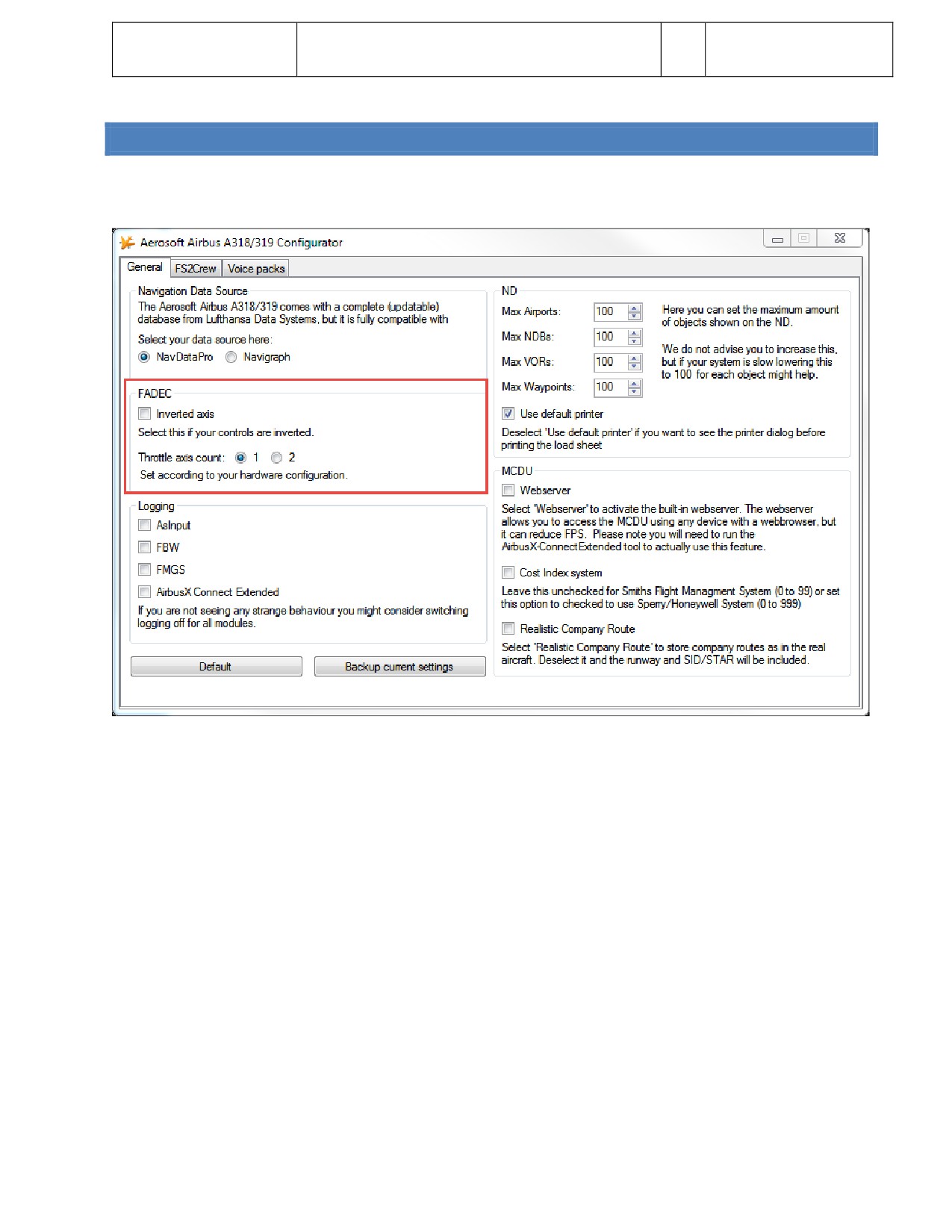
Aerosof
FSX Thrust Lever Setup
Vol
07-01-3
Airbus A320/A321
(only in case you have issues!)
7
28 October 2014
CHECK THE CONFIGURATION
The next thing we are going to check is the setng in the configuraton files of the Aerosof Airbus. Start the Aerosof
Airbus A318/A319 Configurator (it’s in the Windows Startmenu or what Microsof decided to call that this month). You
are looking at the FADEC secton here.
If you found the throtles to work inverted you now know what to click. Make sure you select the right number of
Throtle axis, if you got a dual controller make sure 2 is selected. It is not a bad idea to actvate logging of AsInput
because it can help to debug things. Just close the configurator, the new setngs will be stored.
Now let’s start FSX.
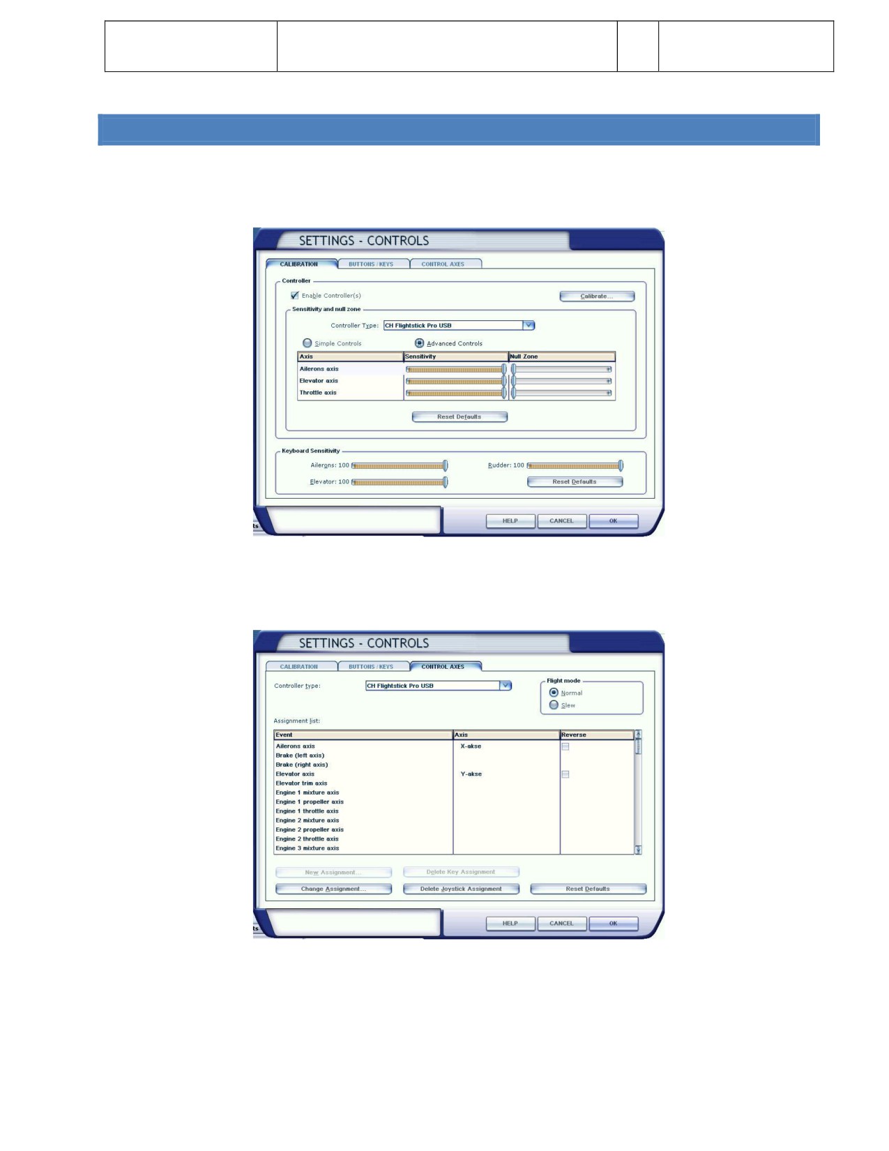
Aerosof
FSX Thrust Lever Setup
Vol
07-01-4
Airbus A320/A321
(only in case you have issues!)
7
28 October 2014
SETTINGS INSIDE FSX
Go slow, make sure you check the images thoroughly so you do not
miss any of the setngs!
In FSX select “Setngs”, then “Controls…”. We’ll look at the CALIBRATION tab first
Note that preferably the Null Zones should be set to minimum and Sensitvity set to Maximum.
Now click the CONTROL AXES tab. If you only have a single joystck with one throtle axis, the FSX controller menus
should look like this:
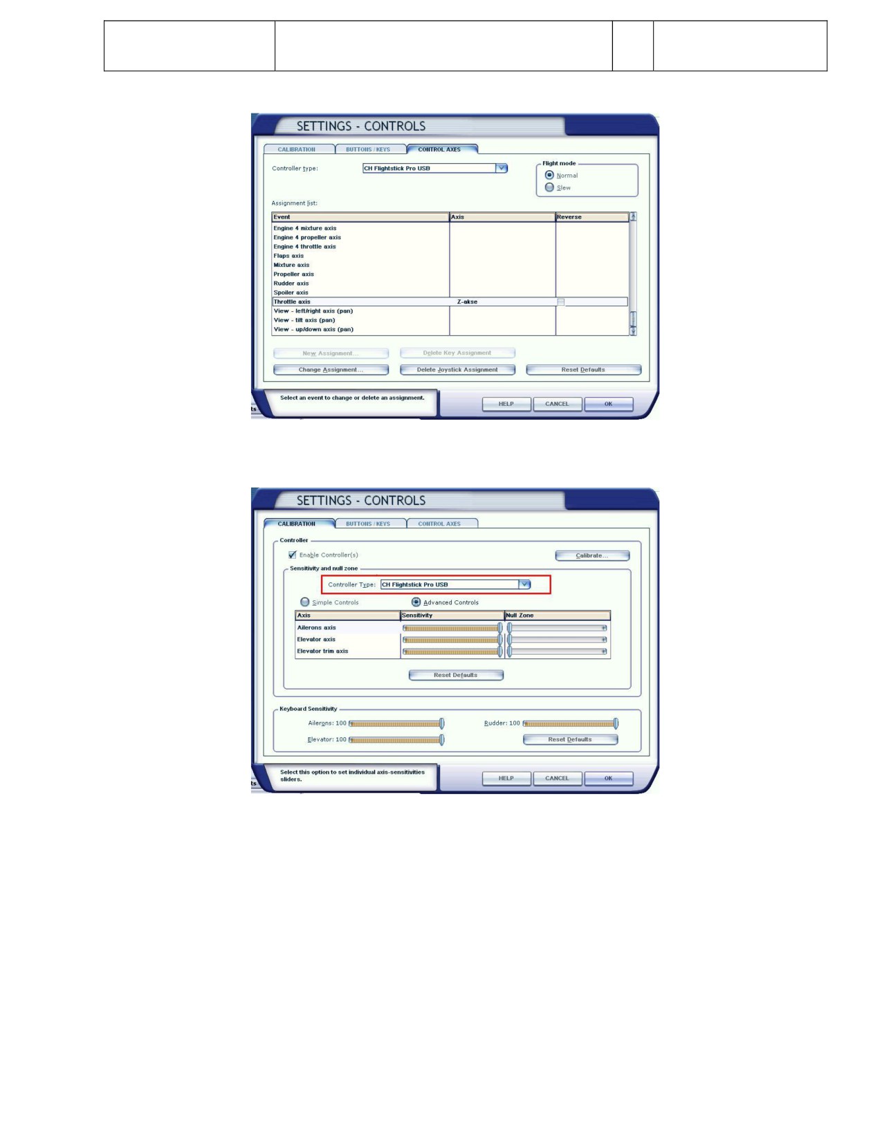
Aerosof
FSX Thrust Lever Setup
Vol
07-01-5
Airbus A320/A321
(only in case you have issues!)
7
28 October 2014
If you got an advanced setup with joystck/yoke, throtle quadrant and pedals, then it could look like this:
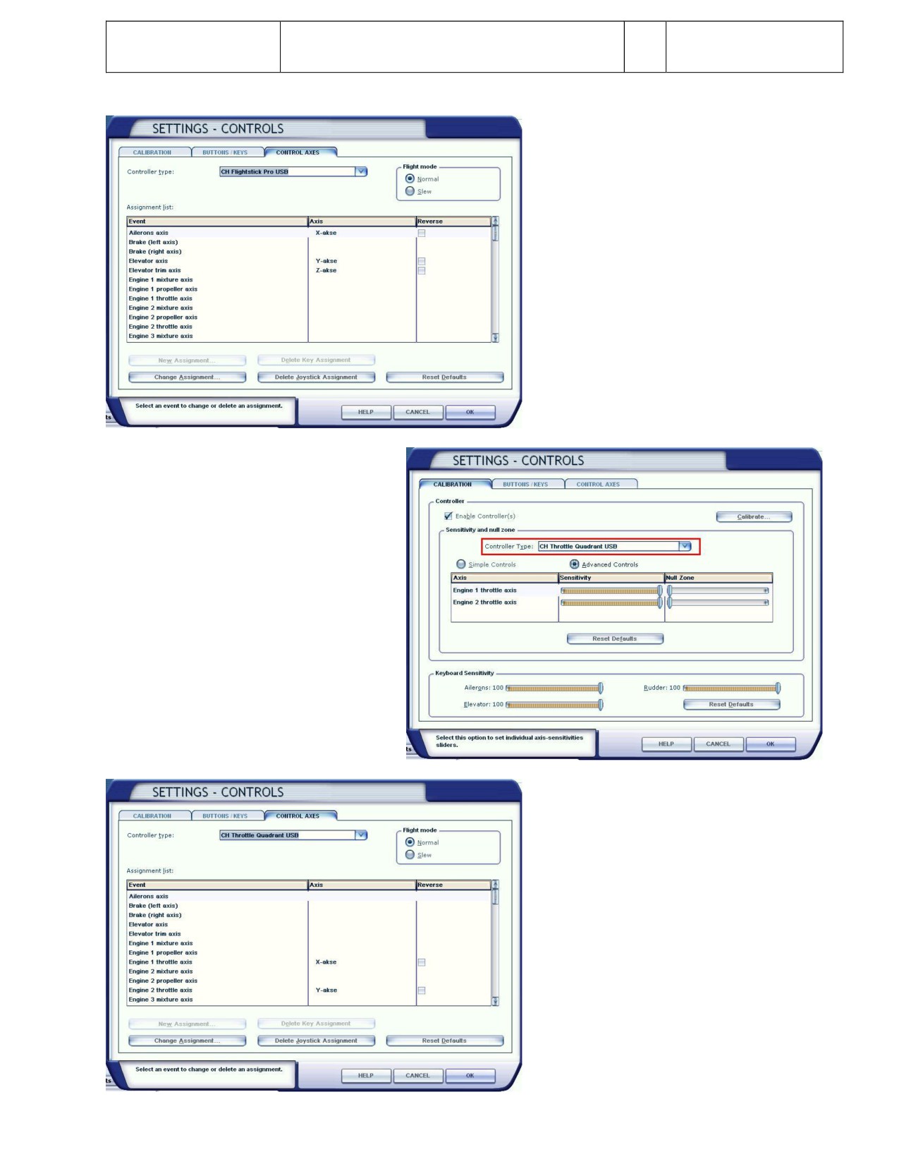
Aerosof
FSX Thrust Lever Setup
Vol
07-01-6
Airbus A320/A321
(only in case you have issues!)
7
28 October 2014
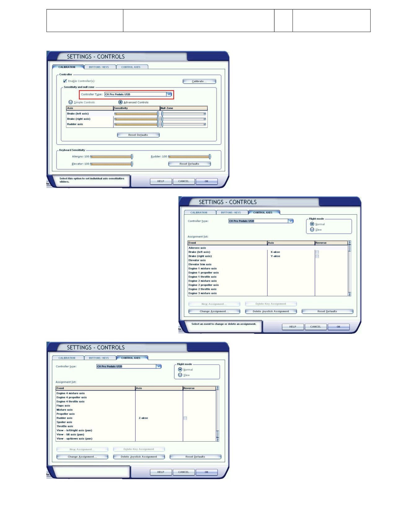
Aerosof
FSX Thrust Lever Setup
Vol
07-01-7
Airbus A320/A321
(only in case you have issues!)
7
28 October 2014
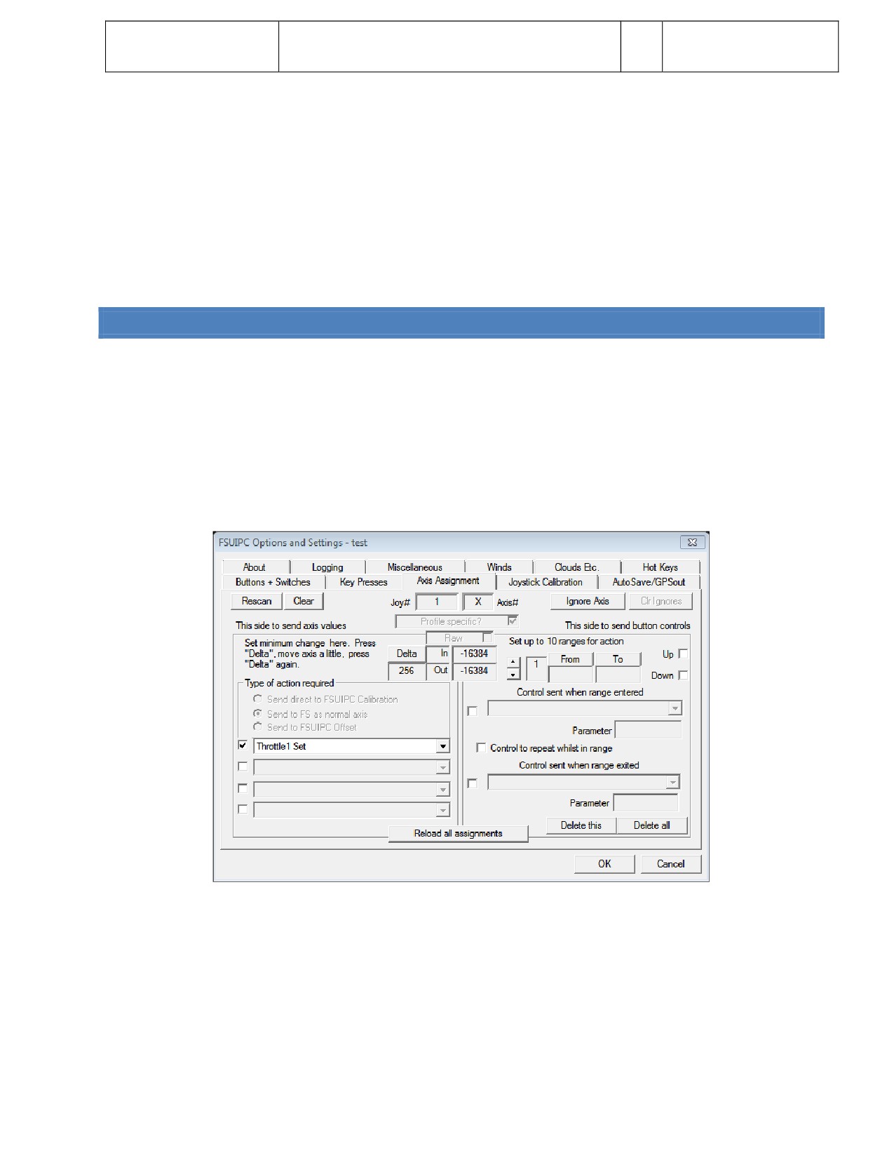
Aerosof
FSX Thrust Lever Setup
Vol
07-01-8
Airbus A320/A321
(only in case you have issues!)
7
28 October 2014
Please go through each and every controller you have atached to your system in the FSX controller menu and verify
that all axes for the various controllers are setup correctly, and more important, that there are no double assignments,
like “ENGINE 1 THROTTLE SET” assigned to both Your Throtle quadrant and Pedals.
If more than one hardware axis is setup for the same engine in FSX, the throtle(s) will simply NOT work with the Airbus.
We have seen quite a few customers where this had happened.
Afer assigning the various controllers and their axes, you should
close down FSX and restart it, otherwise the new setngs might not
be saved correctly.
USING FSUIPC WITH AXES NOT ASSIGNED IN FSXCONTROLLER MENU
We have seen a lot of users who define the axes not via the standard FSX routnes but via FSUIPC. Ofen this is simply
not needed!
You do NOT need FSUIPC for the Aerosof Airbus models, you will
only need FSX.
If using you are using FSUIPC assignment, make sure that the throtles are not assigned in the FSX controller menu.
Open the FSUIPC menu and go to Axis assignment and set a checkmark in Aircraf specific? Checkbox.
Setup each throtle axis to read like this:
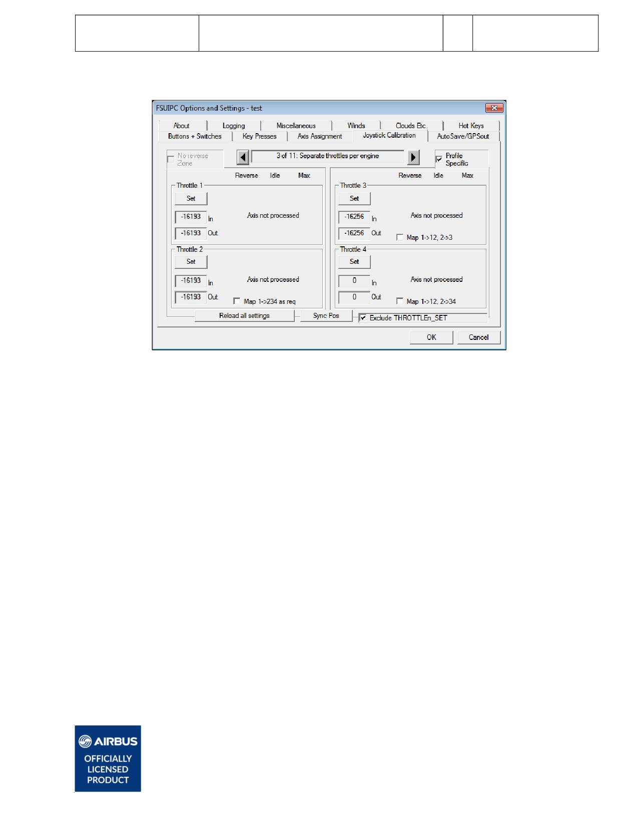
Aerosof
FSX Thrust Lever Setup
Vol
07-01-9
Airbus A320/A321
(only in case you have issues!)
7
28 October 2014
Then select the Joystck calibraton tab and check it look like this:
You will need to repeat this for each of the Airbus models you fly.
With the above setup you won´t have reverse thrust with your
hardware levers, but will need to use F2 to engage revers thrust.
Another soluton can be found here:
htp://forum.aerosof.com/index.php?/topic/60794-ch-throtle-quadrant-idle-thrust-woes/#entry432569
If you followed this instructon, the throtles should work correctly for the Aerosof Airbus aircraf!
All rights reserved. Officially licensed by Airbus.
AIRBUS A320/A321
Volume 8
The Weird And Wonderful Airbus Logic
Version 01-03-001
RECORD OF REVISIONS
revision n°
Issue date
Release
Descripton
001
Aug 20, 2014
1.00
completon
Aerosof
Vol
8-03-1
The Weird And Wonderful Airbus Logic
Airbus A320/A321
10
28 October 2014
CONTENTS
THE WEIRD AND WONDERFUL AIRBUS LOGIC
2
AUTOMATION
2
FLY BY WIRE
2
DARK COCKPIT CONCEPT
3
THRUST LEVERS THAT ARE MODE SELECTORS
3
THOSE PESKY FCU BUTTONS
4
LAWS AND PROTECTIONS
4
NORMAL LAW
4
ALPHA FLOOR PROTECTION
5
PHASES
5
PHASE TRIGGERS
6
MODES
6
MINIMUM GROUND SPEED
7
SPEED REFERENCE SYSTEM
8
FLAPS 1
8
Aerosof
Vol
8-03-2
The Weird And Wonderful Airbus Logic
Airbus A320/A321
10
28 October 2014
THE WEIRD AND WONDERFUL AIRBUS LOGIC
In the last few years we have seen that many pilot who were used to Boeing (and more ‘standard’ logic)
have problems understanding the logic of Airbus. We’ll try to discuss the most confusing and ofen illogical
aspect in this document.
This is not a highly technical document and people accustomed to Airbus logic will not need it. In fact they
might find it lacking in detail or inconsistent. But if you are a real Airbus virgin you will appreciate the
informaton.
AUTOMATION
Almost everything that can be automated is automated and handled without any need for operator
interventon. You just tell the aircraf what you want and it will try to do it. This seems logical these days
but when Airbus started with this it was a strange concept. A fine example is the window ant-icing systems.
As they are fully automatc and we do not spend a lot of tme on failures (as far as I could see a serious
problem resultng of a failure of the ant-icing system has never occurred in millions of flight hours) we
simply do not model them in our simulaton. There is no need to. As far as a real pilot is aware they simply
take care of the icing issues without bothering the crew.
Airbus pilots call it ‘automagically’. You should not always try to understand the logic of the systems
(certainly not when you are busy), just accept that the aircraf will try to assist you in every stage of the
flight.
FLY BY WIRE
Of course this is the big one and the thing that set Airbus Aircraf apart from others for a long tme. It’s a
simple concept, the pilot talks to the computer and the computer talks to the aircraf, but it has a profound
effect on every aspect of the flight. It is best explained by a comparison. As the pilot in a Boeing 737 pulls
hard on the yoke the aircraf will pitch up and it will keep pitching up untl thing go horribly wrong. If you
do the same in an Airbus the computers would try to figure out what you actually wanted and then try to
get it done for you. As it will understand you want to go up fast it will allow you to pitch up to a maximum
(but stll safe) angle and when you are running out of airspeed it will increase thrust to TOGO (Go Around,
the maximum amount of thrust possible). When even that does not keep enough air going over the wings it
will lower the nose to increase speed. The FBW systems also prevent the pilot from doing silly things like
stalling the aircraf or doing barrel rolls.
The controversy between FBW pilots and non FBW pilots will probably never end. There is a lot to be said
for each philosophy. While FBW will make flying inherently safer by preventng mistakes it also limits the
opton a pilot has to get out of a bad situaton. There is one fine example of a situaton where the
automaton helped. During the US Airways crash in the Hudson the pilot had to ditch with minimal ground
speed and minimal vertcal speed. To do this he simply had to pull the control fully back. The aircraf knew
the weight of the aircraf and the environmental conditons so it knew the stall speed. It sensed the stck
being pulled back fully but as it had no running engines it simple selected the best opton and that was to
slowly descend at a speed just above stall. In a Boeing the pilot would have to very carefully maintain that
minimal speed untl touch down. That is difficult in a normal situaton and neigh impossible in an
emergency.
Aerosof
Vol
8-03-3
The Weird And Wonderful Airbus Logic
Airbus A320/A321
10
28 October 2014
Another very important aspect of FBW is that when the pilot does not give any input the aircraf will stay
on its current flight path. Best explained with an example. Take an Airbus up to 5000 feet, bank it a bit and
let go of the side stck. Then go have diner. When you come back the aircraf will stll be at the same bank
and making large circles in the sky. A non FBW aircraf would be flying a straight course and it would level
out. This may sound not too important, but consider what happens when you extend the gear. That
increases drag and because they are positoned below the CoG they will cause a pitch down movement the
pilot has to correct. In an FBW aircraf this would happen automatcally and the aircraf would not pitch
down.
In very simple terms: When you point a FBW aircraf somewhere it will go there as long as it has enough
energy.
DARK COCKPIT CONCEPT
Airbus understood that the modern cockpit crew has a huge amount of informaton to process. To help
with that the cockpit is designed with the ‘dark cockpit concept’. Basically it means that if a system is
running normal there is no indicaton. No green light, no pressure indicaton, just nothing. Only when there
is an abnormality will the system try to draw your atenton. Even when there is a problem and the systems
were able to sort things out it might not be shown untl the flight is over! These days Boeing also adheres to
this concept in the 777 and to some degree in the MD11.
Of course some control do need to give some feedback and this is done in green (all okay) and blue (stll
okay).
THRUST LEVERS THAT ARE MODE SELECTORS
The thrust levers might be big and obvious things in the Airbus cockpit but they are hardly used. In a
standard flight the pilot only touches them a few tmes:
TAXI: the thrust levers behave like normal Thrust Levers.
TAKE-OFF: Pilot advances the thrust levers to the FLEX or TOGA indent.
AFTER TAKE-OFF: Pilot puts Thrust Lever on CLIMB indent.
And now comes the funny part. It stays in climb setng the whole flight untl a few seconds before landing!
To remind the pilot he need to do something with those levers the aircraf even tells him exactly what to do
with the ‘retard…retard’ call. So the Airbus cruises, descends and lands with the Thrust Lever set in the CLB
(Climb) setng.
AFTER LANDING: Pilot closes Thrust Lever and actvates reverse thrust.
So in the air the thrust Levers are used to select the FADEC (the computer that controls the thrust output of
the engines) mode and not the amount of thrust they provide.
Aerosof
Vol
8-03-4
The Weird And Wonderful Airbus Logic
Airbus A320/A321
10
28 October 2014
THOSE PESKY FCU BUTTONS
The butons on the FCU (the Flight Control Unit, on the glare shield) can be pushed or pulled and this leads
to endless confusion for new pilots. Yet there is a great way to remember what is what:
PUSH: you push control from you to the aircraf and go into MANAGED MODE. The aircraf will
now fly the route (with alttudes and speed etc) programmed in.
PULL: you pull control from the aircraf to yourself and go into SELECTED MODE. You now have to
tell the aircraf what to do.
You’ll never be confused again.
LAWS AND PROTECTIONS
Our airbus project is built to be used as 99.9% of all flights are flown. Without serious failures and without
the need for the systems to leave NORMAL law mode. However it is good to know about the modes!
There are 5 laws (but each has a ground and flight mode):
1. NORMAL LAW
2. ALTERNATE LAW
3. ALTERNATE LAW (without speed stability)
4. DIRECT LAW
5. MECHANICAL BACK-UP
And you can now forget about that list because when the shit hits the fan and the systems degrade into
‘lower’ modes even extremely well trained pilots will not know in what modes they are. That’s fine as long
as you keep flying the aircraf. The laws are there to make sure you get at much help from the systems as
possible.
NORMAL LAW
In normal law the aircrafs computers will provide as much protecton as possible. When the aircraf
threatens to go into an abnormal flight conditon (in other words, gets too close the edge of the flight
envelope) the systems will try to prevent it. When the aircraf gets into an abnormal flight conditon the
systems will try to correct it. Here is what it does:
LOAD FACTOR LIMITATION: prevents high G-loads that are unpleasant for the passengers and
potentally dangerous for the airframe. The system will try to stay between +2.5G and -1.0G. A
serious rollercoaster will be designed with these same limits in mind btw.
PITCH ATTITUDE PROTECTION: if there is one thing that your passengers will not like is going
steeply up or down (they might be more bothered by the later and so should you). The system
will try to stay between 30° nose up and 15° nose down. At low speed and extended flaps the nose
up limitaton will lower to 20°)
HIGH ANGLE OF ATTACK PROTECTION: as we all know your wings will stall when your angle of
atack (the angle between the wing and the oncoming air) is too great. That’s why the systems will
try to prevent the aircraf getng into this situaton.
HIGH SPEED PROTECTION: going too slow is dangerous but going to fast as well. Your Airbus will
prevent you from racing other aircraf to the airport.
Aerosof
Vol
8-03-5
The Weird And Wonderful Airbus Logic
Airbus A320/A321
10
28 October 2014
BANK ANGLE PROTECTION: another things your passengers will not like is to look out of the
window and stare direct at the ground. But also at high bank angles you will lose a lot of lif and
speed and G-loads will increase rapidly. That’s why the Airbus systems will prevent a very steep
bank. It will let you bank up to 67° and when you let go of the stck will return to 33°.
ALPHA FLOOR PROTECTION
A good example (and perhaps the most important) of the protectons is the alpha floor protecton. It’s
something every airbus pilot has to demonstrate on check flights and you can do the same. It’s safe and its
fun.
1. Disengage Auto-Pilot and Auto-Thrust Lever
2. Switch off the Flight Director
3. Retard Thrust Lever and let the speed go down to ‘green dot’ (the lowest safe speed at that
moment).
4. Now imagine an aircraf popping up and you have to avoid hitng it. Initate a move UP and RIGHT
(forcefully!) to avoid a midair collision and observe what happens.
Clearly the aircraf will rapidly run out of airspeed and something needs to happen. Thankfully the Airbus
systems will detect this problem and it will initate the alpha floor protecton. The trust will go into TOGA
(the maximum available) mode and will stay there untl the pilot tells it otherwise. The other protecton will
prevent you from startng a loop or a roll. Although very close to the edge of the flight envelope the aircraf
will stay controllable during the whole procedure!
Oh, you want to know how to get back to stabilized flight?
1. Push forwards on the stck to reduce the angle of atack
2. Level the wings and let the aircraf ‘fly out of’ the problem. But you are about to face a new
problem as speed will increase rapidly and you could go from too slow to too fast in seconds!
3. Disengage Auto-thrust again by pushing the side buton on the Thrust lever.
4. Select a safe speed on the FCU (for example 250 Knots).
5. Select both Flight Directors on again.
6. Re-engage Auto-thrust with the FCU A/THR buton.
7. Set Thrust lever in CLIMB detent.
8. Re-engage Auto-pilot and establish normal flight.
9. Might not be a bad idea to talk to the passengers and to tell the cabin crew to distribute drinks for
the adults and toys for the kids.
PHASES
In Airbus logic every flight is divided into stages and stages are very important to understand the logic of
the Airbus systems. Consider a stage to be a combinaton of system setngs and parameters. There are 8
phases:
PREFLIGHT
TAKE_OFF
CLIMB (CLB)
CRUISE (CRZ)
DESCENT (DES)
Aerosof
Vol
8-03-6
The Weird And Wonderful Airbus Logic
Airbus A320/A321
10
28 October 2014
APPROACH (APPR)
LANDING
GO AROUND
In a flight, even a very short one, all these stages will follow each other (or course expect the Go Around).
When this chain of phase is not completed some of the automaton of the aircraf systems will not be
available!
PHASE TRIGGERS
A phase trigger switches one phase into the next phase. These triggers (events) can be complex but can be
simplified like this:
PREFLIGHT
o Thrust levers to FLX or TOGA
TAKE_OFF
o Reaching ACCEL alttude that was set in the MCDU PERF page
CLIMB (CLB)
o Reaching cruise alttude that was set in the MCDU PERF page
CRUISE (CRZ)
o Manual actvaton of descent and leaving cruise alttude (keep in mind that in most
setngs the Airbus will not start to descent without pilot interacton!)
DESCENT (DES)
o Manually actvate and confirm APPR in the MCDU PERF page
APPROACH to LANDING
o Touchdown or Autopilot disconnected
APPPROACH to DONE
o
30 seconds afer landing and INIT or PERF pb is pressed
Alternatve from APPROACH to LANDING:
APPROACH to GO AROUND
o Thrust Levers to TOGA while in APPROACH phase
MODES
Next to phases you got to understand Modes. They are not as complex as Phases as there are only three (I
copied this from airbusdrivers.net, a great resource for any Airbus enthusiast) but as they change the way
controls work they are important.
Ground Mode
o Actve when aircraf is on the ground.
o Direct proportonal relatonship between sidestck deflecton and flight control movement
o Direct proportonal relatonship between the Thrust Lever levers control setng and
thrust.
o Is actve untl shortly afer lifoff.
o At touchdown, ground mode is reactvated and resets the stabilizer trim to zero.
Flight Mode
o Actve shortly afer takeoff and remains actve untl shortly before touchdown.
Aerosof
Vol
8-03-7
The Weird And Wonderful Airbus Logic
Airbus A320/A321
10
28 October 2014
o Sidestck deflecton and load factor imposed on the aircraf are directly proportonal,
regardless of airspeed.
o With sidestck neutral and wings level, system maintains a 1 g load in pitch.
o No requirement to change pitch trim for changes in airspeed, configuraton, or bank up to
33 degrees.
o At full af/fwd sidestck deflecton system maintains maximum load factor for flap
positon.
o Sidestck roll input commands a roll rate request.
o Roll rate is independent of airspeed.
o A given sidestck deflecton always results in the same roll rate response.
o Turn coordinaton and yaw damping are computed by the ELACs and transmited to the
FACs.
o No rudder pedal feedback for the yaw damping and turn coordinaton functons.
Flare Mode
o Transiton to flare mode occurs at 50' RA during landing.
o System memorizes pitch attude at 50' and begins to progressively reduce pitch, forcing
pilot to flare the aircraf
o In the event of a go-around, transiton to flight mode occurs again at 50' RA.
MINIMUM GROUND SPEED
Minimum Ground Speed (or MINI GS) is rather clever system that protects the aircraf from the dangers of
microburst related windshear. A microburst is a downwards moving pocket of air that can be highly
dangerous to aircraf on approach. Not only because it will ‘push’ the aircraf down but even more because
the aircraf can get in a sudden tail wind situaton that will reduce list or cause a sudden and unexpected
stalls.
MINI GS functons by increasing the Final Operatng Airspeed thus enhancing the protecton against stall.
The increase in based on the wind speed (taken from ATIS) inserted by the crew in the MAG WIND item of
the PERF/APPR page and will only functon in MANAGED speed mode.
On the Professional Pilots Rumour Network it was explained by Chris Scot like this: “GS-MINI is, as the
name implies, based on a minimum ground speed. Before the approach, once the crew can predict with
reasonable confidence what the surface-wind is likely to be at the landing threshold, they enter the figure
into the approach Performance page. The FMS works out the correct Vapp, which is a threshold IAS based
on weight and headwind component.
Now: let's take the sea-level ISA case, where IAS=TAS; a Vapp of 130kts; and a predicted headwind of 10kts
entered into the Performance page. On a conventonal airplane stabilised at Vapp (130kts) at a height of
500f, if the headwind is 30 kts the GS will be 100kts. But when it comes over the threshold, where the
headwind is only 10kts, it will need to have accelerated to a GS of 120kts to maintain the required Vapp of
130. This will require a lot of extra energy (from the engines), which may cause problems, partcularly if the
loss of headwind happens suddenly (like at night).
It makes sense, therefore, to ensure that the GS remains at or above 120kts throughout the approach, even
though this initally results in a higher IAS (150kts at 500f in this case). The "managed" speed (IAS) target
on the ASI (used by the pilot and the autot hrotle) goes up and down with the headwind, but never below
Vapp. Reaching the threshold, provided the actual headwind equals the predicted figure, the speed target
Aerosof
Vol
8-03-8
The Weird And Wonderful Airbus Logic
Airbus A320/A321
10
28 October 2014
will be Vapp. If the wind is higher, the speed target will be above Vapp. This should not be a problem for
stopping in the runway length, because the GS will be no higher than originally planned.
In practce? Works very well, partcularly using manual Thrust Lever, provided the pilot uses the "managed"
speed as a target speed; not a minimum speed. The power changes required in windshear are far less than
on a conventonal aeroplane, because the GS (kinetc energy) is steady.”
Using MINI GS is not without drawbacks. You might see that your managed speed (and thus ground speed)
fluctuates and in a busy environment this could cause problem in the traffic flows.
SPEED REFERENCE SYSTEM
The Speed Reference System (SRS) will guide the aircraf along the vertcal path during the take-off phase
(and go around stage). It prevents the aircraf from climbing too steep and loosing airspeed.
It is armed when V2 in entered on the PERF page of the MCDU and flaps/slats not fully retracted.
It is triggered by the thrust levers placed in the take-off positon and will control pitch afer rotaton and it
will maintain an airspeed between V2+10 knots and V2+15 knots and at minimum a 120 FPM climb. When
vertcal speed drops below 120 FPM the system allows the speed to decrease to V2.
FLAPS 1
Another fine example of Airbus logic. If you move the flaps lever from 0 to 1 airborne, the flaps will not
move! Only the slat (at the front of the wing) will deploy. Of course that would be too easy so on the
ground flaps 1 WILL extend the flaps and when you retract them from 2 to 1 they will stay out. Don’t even
try to get your head around this, accept that the engineers thought about this and that it is best for the
aircraf.
All rights reserved. Officially licensed by Airbus.
Aerosof Airbus
Vol
09-01-06 Page 1
CONNECTED FLIGHT DECK FLOWS
A318/A319/A320/A321
9
08 April 2015
Aerosof Airbus
A318/A319/A320/A321
Volume 9
Connected Flight Deck Flows
Robert Miroszewski & Emanuel Hagen
Version 09-002
RECORD OF REVISIONS
revision n°
Issue date
Release
Descripton
001
Mar 12, 2015
1.30
First issue
002
Apr 8, 2015
1.30
Added Introducton text & minor flow changes
Aerosof Airbus
Vol
09-01-06 Page 2
CONNECTED FLIGHT DECK FLOWS
A318/A319/A320/A321
9
08 April 2015
Welcome to your Mult Crew introducton course!
At the beginning let us discuss some of the details of mult crew operatons you may not be used to from
your previous operaton in single pilot cockpits. Even if you already have previous experience in a mult crew
cockpit you should read this secton to get comfortable with the way the Airbus should be operated to
ensure you and your crew member will fly it safely!
First of all you will notce the most obvious: There is someone else sitng next to you, including all the
advantages, but also all the weaknesses of humans. This is especially true concerning we are untrained
simmers, who, unlike professional pilots, do not have a type ratng.
As you might already know from your previous flight experience there are a few golden rules of operatng
an Airbus, which are especially important when flying it with two crew members.
You can find those in a very nice document by Airbus and the FAA here:
htp://lessonslearned.faa.gov/IndianAir605/AirbusSafetyLib_-FLT_OPS-SOP-SEQ03%20-
Take your tme to read and fully understand them. Always be aware of the Golden Rules when flying the
Airbus!
Now let's contnue with some specific aspects of operatng with another crew member. You may have flown,
or when no second pilot is available will stll fly, with addons providing a simulaton of a first officer. It will
not take long for you to notce that these are, as long as they understand your commands, more or less
“perfect” in doing their flows, etc.
This is not the case any longer!
Flying with a real person means he is going to make mistakes, not doing what you want him to do and
misunderstanding each other. This is normal and we have to deal with it. Over the last decades procedures
have been developed to counteract the human factors while flying. They can't prevent all kind of mistakes,
but they will help managing them!
Crew Resource Management (CRM)
What I'm outlining here is basically just a very small part of what real pilots learn in a CRM course. The real
course lasts several days and includes in depth discussions of how to react in certain situatons, etc.
Some people tend to put a CRM course on par with an actor training.
We're just doing a brief summary on this here, however once you have read and understood it, it will greatly
enhance your experience flying the Airbus in a mult crew environment.
All of the following sort of belongs to CRM, but for a beter readability I'll split it in several parts combined
with the most important informaton you need to fly the Airbus with a real person as your captain or first
officer:
Aerosof Airbus
Vol
09-01-06 Page 3
CONNECTED FLIGHT DECK FLOWS
A318/A319/A320/A321
9
08 April 2015
Know what your Crew member is doing
Probably the most important lesson to be learned is to check each other.
Just like a real crew that keeps watching each other you should also have a look at your crew member!
As we are all doing this in our free tme, sitng at home and probably having our
Wife/Husband/girlfriend/boyfriend/mistress/children around us we will do mistakes. This is normal and
there is nothing wrong with it.
Talk about it with your other crew member and let him know about mistakes you made. If he knows about
your mistakes he can watch you.
Flying is a constant learning experience and as such it is good to know which mistakes others make as you
may also make them without knowing about it!
My flight instructor always told me: “You should stop flying when you say you don't learn something new
any longer!”
So, keep watching your crew member and correct him when necessary. Doing mistakes is human and there
is nothing wrong with it as long as you acknowledge and correct them.
Sterile Cockpit
During high workload communicaton should be kept to a minimum necessary to operate the Airbus safely.
Such situatons are taxi, takeoff, climb out, approach and landing.
This not only includes communicaton, but also entering data into the systems (partcularly the FMGS), etc.
As a rule of thumb the Sterile Cockpit concept should be applied below FL100/10.000f, but also at any
other tmes of high workload.
Callouts
Just like in ATC communicaton there are certain standard phrases that are used for communicaton
between the crew in an Airbus (and in any other aircraf).
In the following document you can find some more informaton on this topic:
Aerosof Airbus
Vol
09-01-06 Page 4
CONNECTED FLIGHT DECK FLOWS
A318/A319/A320/A321
9
08 April 2015
I will list the most important callouts and some standard calls for procedures you should be familiar with
which are not listed in the doc above:
I have control/You have control
Set Heading/Speed/Alttude xxx
→ If a change in FCU alttude is made always check it on the PFD and reply Alttude/FL xxxx to
make sure the correct value is set and „seen“ by the System! When flying in managed modes
keep in mind the FMGS may overwrite your set alttude due to a CSTR.
[Insert System name] ON/OFF
Gear UP/DOWN
Altmeter reset:
PF: „altmeters“
PM: „standard, passing FLxxx“
PF: „standard, passing FLxxx“
Approaching FCU alttude
PM: „1000“
→ The PM has to call 1000 if the aircraf is 1000f before the assigned alttude. Some airlines
also have a 2000 or a 500 call, but 1000 is the most common one.
FMA Callouts
I'm making this as a separate secton as it is very important you are aware of these!
As you already know from the Golden Rules both pilots should always be aware of the FMA, regardless of
who the PF is and who is the PM. Therefore it is important that each change in the FMA is announced.
Announcements are to be made by the PF, however the PM shall announce the new mode if the PF does
not make a tmely announcement. Give him a short tme to notce the change though. Nothing can be more
annoying than someone always doing your announcements if you miss them by half a second!
A missing announcement may indicate an incapacitaton of the other crew member!
Task sharing/SOP
A proper sharing of tasks is needed in order to operate the aircraf in a professional and safe manner.
Following a Standard Operatng Procedures (SOP) is the only way to operate the aircraf tme and fuel
efficient and to create the base for proper CRM.
In the real world each operator creates their own SOP which tells exactly which tasks are to be performed
by which pilot. We have included a detailed SOP in this manual, which you should use to fly the Airbus.
If every pilot of our Airbus operates it according to the SOP we included you will have no problems, even
when flying with someone whom you have never seen or talked to before, so you could basically fly with
each and every pilot who has our Airbus!
Do not worry if you see something done differently in some video. Keep in mind each airline may do things
different than another.
Aerosof Airbus
Vol
09-01-06 Page 5
CONNECTED FLIGHT DECK FLOWS
A318/A319/A320/A321
9
08 April 2015
Briefing
The briefing is one of the parts most of us will not be very familiar with.
Even worse, many of us may have already adapted a wrong way of conductng a briefing as there are several
addons out there which include briefings, but to be honest, so far I haven't seen a single addon doing a
briefing correctly and as it would be done in real life.
Only a good briefing can lead to a good flight with both crewmembers knowing what will be done.
Knowing what the other pilot plans to do is the key element of flying with each other and to remain ahead
of the aircraf. In fact there is a lot more behind a briefing than most of us would think seeing a video of a
real crew conductng a briefing.
A detailed guide how to conduct a proper briefing is published by Airbus here:
You should follow this guide at all tmes when briefing your other crew member.
Make sure to plan with enough tme to prepare and conduct the briefing.
Equally important is the usage of the same charts by both crew members, in order for both to get the same
informaton. Of course it's ideal if the charts even comply with the database. If they are not up to date make
sure to check the procedure entered in the FMGS with your charts to make sure no sudden surprise happens
during the approach!
Below you will find the flows for our SOP divided into Captain/First Officer and Pilot Flying/Pilot Monitoring
sectons.
We recommend always to fly according to these flows, even when flying the Airbus in a single pilot
operatons in order to get used to them.
I'm looking forward to see you in the air and wish you always three greens!
Emanuel Hagen
Aerosof Airbus
Vol
09-01-06 Page 6
CONNECTED FLIGHT DECK FLOWS
A318/A319/A320/A321
9
08 April 2015
COCKPIT PREPARATION FLOWS
PF
PM / PNF
PFD/ND
BRTECAMS
BRT
FLOOD LT
AS RQRD
INTEG LT
AS RQRD
OVERHEAD PANEL
PEDESTAL
BATTERY 1+2
ON
PARKING BRAKE
SET
EXT POWER
ON
FLAPS
VERIFY 0
RCDR GND CTL
ON
SPEEDBRAKE
RET/DISARM
ADIRS
NAV
ENG MASTER 1+2
OFF
ELEC HYD PUMP
ON
ENG MODE SEL
NORM
FUEL PUMPS
ON
THRUST LEVERS
IDLE
ENG GEN
ON/FAULT
TRANSPONDER
STBY
PACK 1+2
ON
RADIO PANEL
ON
ENG BLEED 1+2
ON
FREQ
SET
HOT AIR
ON
ENG ANTI ICE
OFF
ECAM / MAIN PANEL
PROBE HEAT
AUTO
ECAM RECALL
SELECT
EMER EXIT LT
ARM
L/G LEVER
DOWN
CABIN SIGNS
ON
DOORS
OPEN/AS RQRD
NAV LT
ON
ANTI SKID
ON
GPWS
ON
ATIS/ATC CLRN
OBTAIN
MCDU
SET
SQUAWK
SET
---------------------------- TAKEOFF BRIEFING -----------------------------
TAKEOFF BRIEFING
PERFORM
GLARESHIELD
GLARESHIELD
BARO REF
SET
BARO REF
SET
FD
ON
LS
AS RQRD
ND MODE/RANGE
SET
VOR/ADF
SELECT
FCU
SET
FCU
VERIFY AND COMPLETE
PEDESTAL
MCDU
CHECK IRS ALIGN
Aerosof Airbus
Vol
09-01-06 Page 7
CONNECTED FLIGHT DECK FLOWS
A318/A319/A320/A321
9
08 April 2015
BEFORE PUSHBACK / START FLOWS
PF
PM / PNF
TO DATA
CHECK/REVISE
BOARDING
VERIFY COMPLETE
MCDU
PERF TO
FUELING
VERIFY COMPLETE
DOORS
CLOSE
PARKING BRAKE
ON
APU
START
CHOCKS
REMOVE
APU BLEED
ON
TRAFFIC CONES
REMOVE
EXT POWER
OFF
EXT POWER
DISCONNECT
--------------------- BEFORE START C/L TO THE LINE ----------------------
WINDOWS/DOORS
CHECK
PUSHBACK/START CLEAR
OBTAIN
THRUST LEVERS
IDLE
WINDOWS/DOORS
CHECK
PARKING BRAKE
AS RQRD
BEACON
ON
------------------- BEFORE START C/L BELOW THE LINE --------------------
BEFORE START/PUSHBACK CHECKLIST
COCKPIT PREP
COMPLETED
WHEEL CHOCKS
REMOVED !pm!
CABIN SIGNS
ON/AUTO
ADIRS
NAV
FUEL QUANTITY
_____KG
TO DATA
SET
BARO REF
____SET !B!
-----------------------------------
WINDOWS/DOORS
CLOSE
!B!
BEACON
ON
THRUST LEVERS
IDLE
PARKING BRAKE
AS RQRD
Aerosof Airbus
Vol
09-01-06 Page 8
CONNECTED FLIGHT DECK FLOWS
A318/A319/A320/A321
9
08 April 2015
ENGINE START FLOWS
CAPT
FO
ENG MODE SEL
IGN/START
ANNOUNCE
“STARTING ENG 2”
MASTER SW 2
ON
START VALVE
N2
IGNITER
FUEL FLOW
EGT
CHECK
N1
OIL PRESS
START VALVE CLOSE
50% N2 CFM
42% N2 IAE
ENG IDLE PARAMS
CHECK
ANNOUNCE
“ENG 1 OR 2 STABILIZED”
ANNOUNCE
“STARTING ENG 1”
REPEAT THE START SEQUENCE
AFTER START FLOWS
PF
PM / PNF
ENG MODE SEL
NORM
APU BLEED
OFF
ENG ANTI ICE
AS RQRD
WING ANTI ICE
AS RQRD
APU MASTER
AS RQRD
GND SPLRS
ARM
PITCH TRIM
SETRUD TRIM
ZERO
FLAPS
SET
ECAM STATUS
CHECK
FLT CTL
check
Flt CTL
check
----------------------------- AFTER START C/L ------------------------------
AFTER START CHECKLIST
ANTI ICE
AS RQRD
ECAM STATUS
CKD
PITCH/RUD TRIM
____/ZERO
HAND SIGNAL
RECEIVED
Aerosof Airbus
Vol
09-01-06 Page 9
CONNECTED FLIGHT DECK FLOWS
A318/A319/A320/A321
9
08 April 2015
Taxi FLOWS
CAPT
FO
NOSE LT
TAXI
TAXI CLEARANCE
OBTAIN
RWY TURN OFF
ON
TAXI CLEARANCE OBTAINED:
PARKING brake
OFF
Elapsed time
as RQRD
Thrust levers
as RQRD
brakes
check
Brake press
check zero
Auto brake
max
FLT INSTR/FMA
check
FLT INSTR/FMA
check
RADAR
as RQRD
TO BRIEFING
CONFIRM
TO CONFIG
PRESS
TO MEMO
CHECK NO BLUE
-------------------- BEFORE TAKEOFF c/l to the line ---------------------
BEFORE TAKEOFF FLOWS
CAPT
FO
Brake TEMP
check
Brake FANS
OFF
APPR PATH CLEAR OF TFC
check
TO/LU CLEARANCE
OBTAIN
CABIN CREW
ADVISE
ENG MODE SEL
AS RQRD
TCAS
TA OR TA/RA
THRUST BUMP
AS RQRD
EXT LT
SET
SLIDING TABLE
STOW
PACK 1+2
AS RQRD
SLIDING TABLE
STOW
------------------ BEFORE TAKEOFF c/l BELOW the line ------------------
WHEN LINED UP:
CONTROLS
HAND TO PF
BEFORE TAKEOFF CHECKLIST
FLT CTL
CKD!B!
FLT INSTR
CKD!B!
TAKEOFF BRIEFING
CONFIRMED
FLAPS CONF
FLAPS____!B!
V1, VR, V2, FLX TEMP . ___,___,___/___ !B!
ATC
SET
ECAM MEMO
TAKEOFF NO BLUE
-----------------------------------
CABIN CREW
ADVISED
TCAS
TA OR TA/RA
ENG MODE SEL
AS RQRD
PACK 1+2
AS RQRD
Aerosof Airbus
Vol
09-01-06 Page 10
CONNECTED FLIGHT DECK FLOWS
A318/A319/A320/A321
9
08 April 2015
TAKEOFF FLOWS
PF
PM / PNF
ANNOUNCE
“TAKEOFF”
brakes
RELEASE
THRUST LEVERS
FLEX/TOGA
CHRONO
START
PFD/ND
SCAN
N1 (EPR)
CHECK
BELOW 80 KT:
ANNOUNCE
“POWER SET”
PFD/ENG PARAMS
SCAN
AT 100 KT:
ANNOUNCE
“100 KT”
ANNOUNCE
“Checked”
AT v1:
announce
“v1”
AT vr:
announce
“ROTATE”
When v/s positive:
announce
“POSITIVE CLIMB”
ORDER
“GEAR UP”
l/g
UP
GRND SPLRS
DISARM
NOSE LT
OFF
RWY TURN OFF LT
OFF
AP
AS RQRD
announce
“GEAR UP”
AT THRUST REDUCTION ALT:
THRUST LEVERS
CL
ONE PACK
ON
AT F SPEED:
ORDER
“FLAPS 1”
FLAPS 1
SELECT
ANNOUNCE
“SPD CKD FLAPS 1”
AT S SPEED:
ORDER
“FLAPS 0”
FLAPS 0
SELECT
ANNOUNCE
“SPD CKD FLAPS 0”
2ND PACK
ON
Aerosof Airbus
Vol
09-01-06 Page 11
CONNECTED FLIGHT DECK FLOWS
A318/A319/A320/A321
9
08 April 2015
AFTER TAKEOFF AND CLIMB FLOWS
PF
PM / PNF
APU MASTER
AS RQRD
ENG MODE SEL
AS RQRD
TCAS
TA/RA
ANTI ICE
AS RQRD
--------------------- AFTER TAKEOFF c/l TO the line ---------------------
MCDU
PERF CLB
FCU/FMGS
SET IF AP ON
AT TRANSITION ALT:
BARO REF
STD
BARO REF
STD
------------------- AFTER TAKEOFF c/l BELOW the line -------------------
ENG ANTI ICE
AS RQRD
AT 10000 FT:
EFIS OPTION
ARPT
LAND LT
OFF
RADIO NAV
CHECK
SEAT BELTS
AS RQRD
ECAM MEMO
REVIEW
OPT/MAX ALT
CHECK
SEC F-PLN
AS RQRD
AFTER TAKEOFF CHECKLIST
L/G
UP
FLAPS
RETRACTED
PACKS
ON
-----------------------------------
BARO REF
STANDARD SET !B!
Aerosof Airbus
Vol
09-01-06 Page 12
CONNECTED FLIGHT DECK FLOWS
A318/A319/A320/A321
9
08 April 2015
cruise FLOWS
PF
PM / PNF
EVERY 30 MINS:
MONITOR FLIGHTPATH
FUEL
CHECK
ECAM (ALL PAGES)
CHECK
DESCENT PREP AND DESCENT FLOWS
PF
PM / PNF
LDG ELEV
CHECK
ATIS
OBTAIN
LANDING DATA
PREPARE
GPWS LDG FLAP 3
AS RQRD
---------------------------- APPROACH BRIEFING ----------------------------
APPR BRIEFING
PERFORM
DESCENT CLEARANCE
OBTAIN
ANTI ICE
AS RQRD
DESCENT
INITIATE
MCDU
PROG/PERF DES
DESCENT
MONITOR
SPEEDBRAKES
AS RQRD
WHEN CLEARED TO ALTITUDE:
BARO REF
SET
BARO REF
SET
ECAM STATUS
CHECK
AT 10000 FT:
EFIS OPTION
CSTR
LAND LT
ON
LS PUSHBUTTON
AS RQRD
SEAT BELTS
AS RQRD
RADIO NAV
SELECT/IDENT
NAV ACCURACY
CHECK
Aerosof Airbus
Vol
09-01-06 Page 13
CONNECTED FLIGHT DECK FLOWS
A318/A319/A320/A321
9
08 April 2015
APPROACH FLOWS
PF
PM / PNF
ENG MODE SEL
AS RQRD
SEAT BELTS
ON/AUTO
15 NM FROM TOUCHDOWN:
APPR PHASE
ACTIVATE
OR SET GREEN DOT SPEED
NAV ACCURACY
MONITOR
------------------------------- APPROACH C/L -------------------------------
APPROACH CHECKLIST
APPROACH BRIEFING
CONFIRMED
ECAM STATUS
CKD
SEAT BELTS
ON
BARO REF
____SET !B!
MDA/DH
____SET !B!
ENG MODE SEL
AS RQRD
Aerosof Airbus
Vol
09-01-06 Page 14
CONNECTED FLIGHT DECK FLOWS
A318/A319/A320/A321
9
08 April 2015
FINAL FLOWS
PF
PM / PNF
AT GREEN DOT SPEED:
ORDER
“FLAPS 1”
FLAPS 1
SELECT
ANNOUNCE
“SPD CKD FLAPS 1”
CHECK OR SET S SPEED
TCAS
TA OR TA/RA
When established on approach:
GO AROUND ALT
SET
AT 2000 FT AGL
ORDER
“FLAPS 2”
FLAPS 2
SELECT
ANNOUNCE
“SPD CKD FLAPS 1”
CHECK OR SET F SPEED
WHEN FLAPS 2
ORDER
“GEAR DOWN”
L/G
DOWN
GRND SPLRS
ARM
AUTO BRAKE
AS RQRD
CONFIRM/ANNOUNCE
“GEAR DOWN”
WHEN L/G DOWN, BELOW VFE
ORDER
“FLAPS 3”
FLAPS 3
SELECT
ANNOUNCE
“SPD CKD FLAPS 3”
WHEN FLAPS 3, BELOW VFE
ORDER
“FLAPS FULL”
FLAPS FULL
SELECT
ANNOUNCE
“SPD CKD FLAPS FULL”
CHECK OR SET VAPP
A/THR
CHECK SPD OR OFF
WING ANTI ICE
AS RQRD
EXT LT
SET
SLIDING TABLE
STOWED
SLIDING TABLE
STOWED
CABIN REPORT
OBTAIN
CABIN CREW
ADVISE
-------------------------------- LANDING C/L --------------------------------
landing CHECKLIST
CABIN CREW
ADVISED
a/THR
speed/off
ECAM MEMO
LANDING NO BLUE !B!
Aerosof Airbus
Vol
09-01-06 Page 15
CONNECTED FLIGHT DECK FLOWS
A318/A319/A320/A321
9
08 April 2015
SHORT FINAL FLOWS
PF
PM / PNF
FLT PARAMS
CHECK
Announce any deviaton in excess of:
V/S: 1000 f/min
IAS: speed target + 10 KT; VAPP - 5 KT
At dh/mda + 100 ft:
announce
“HUNDRED above”
At dh/mda:
announce
“minimum”
announce
“landing” or “ga/flaps”
LANDING FLOWS
PF
PM / PNF
AT 20 FEET:
FLARE
PERFORM
ATTITUDE
MONITOR
THRUST LEVERS
IDLE
AT TOUCHDOWN:
REV
MAX
ANNOUNCE
“GRND SPLRS”
BRAKES
AS RQRD
ANNOUNCE
“REVERSE GREEN”
If decelerating:
ANNOUNCE
“DECEL”
AT 70 KT:
REV
CHECK IDLE
ANNOUNCE
“70 KT”
AT TAXI SPEED:
REV
STOW
BEFORE 20 KT:
AUTO BRAKE
DISENGAGE
GO AROUND FLOWS
PF
PM / PNF
THRUST LEVERS
TOGA
ANNOUNCE
“GO AROUND”
ROTATION
PERFORM
FLAPS
RETRACT ONE STEP
ANNOUNCE
NEW FLAPS SETTING
ANNOUNCE
“POSITIVE CLIMB
ORDER
“GEAR UP”
L/G
UP
ANNOUNCE
“GEAR UP”
NAV/HDG
SELECT
AT GA THRUST RED. ALTITUDE:
THRUST LEVERS
CL
AT GA ACCEL ALTITUDE:
SPEED
MONITOR FLAPS
RETRACT ON SCHEDULE
Aerosof Airbus
Vol
09-01-06 Page 16
CONNECTED FLIGHT DECK FLOWS
A318/A319/A320/A321
9
08 April 2015
AFTER LANDING FLOWS
CAPT
FO
AT NIGHT TIME:
AT DAY TIME:
LAND LT
RETRACT
LAND LT
RETRACT
GRND SPLRS
DISARM
SIGNAL FOR PM/PNF TO COMENCE CLEAN-UP
CLEAN-UP:
FLAPS
RETRACT
ENG MODE SEL
NORM
TRANSPONDER
STBY
ANTI ICE
AS RQRD
APU
START
RADAR
OFF/STBY
BRAKE TEMP
CHECK
---------------------------- AFTER LANDING C/L ----------------------------
AFTER landing CHECKLIST
(FO SILENTLY)
GRND SPLRS
DISARMED
FLAPS
RETRACTED
ENG MODE SEL
NORM
APU
AS RQRD
Aerosof Airbus
Vol
09-01-06 Page 17
CONNECTED FLIGHT DECK FLOWS
A318/A319/A320/A321
9
08 April 2015
PARKING FLOWS
PF
PM / PNF
ANTI ICE
OFF
PARKING BRAKE
SET
APU BLEED
ON
ENG MASTER 1+2
OFF
FUEL PUMPS
OFF
GRND CONTACT
ESTABLISHED
ELAPSED TIME
STOP
BEACON LT
OFF
WHEEL CHOCKS
SET
EXT LT
AS RQRDEXT POWER
CONNECT
SEATBELTS
OFFECAM STATUS
CHECK
PARKING BRAKE
AS RQRD
BRAKE FAN
OFF
dUS
DIM
-------------------------------- PARKING C/L --------------------------------
PARKING CHECKLIST
APU BLEED
ON
ENG MASTER 1+2
OFF
ANTI ICE
OFF
SEAT BELTS
OFF
EXT LT
AS RQRD
FUEL PUMPS
OFF
PARKING BRAKE
AS RQRD
SECURING THE AIRCRAFT FLOWS
PF
PM / PNF
PARKING BRAKE
CHECK ON
ADIRS(1+2+3)
OFF
EXT LT
OFF
APU BLEED
OFF
APU MASTER
OFF
EMER EXIT LT
OFF
NO SMOKING
OFF
EXT POWER
AS RQRD
BATTERY 1+2
OFF
----------------------- SECURING THE AIRCRAFT C/L -----------------------
SECURING THE AIRCRAFT CHECKLIST
ADIRS
OFF
NO SMOKING
OFF
APU
OFF
BATTERY 1+2
OFF
Aerosof Airbus
Vol
09-01-06 Page 18
CONNECTED FLIGHT DECK FLOWS
A318/A319/A320/A321
9
08 April 2015
CHECKLISTS
BEFORE START/PUSHBACK CHECKLIST
APPROACH CHECKLIST
COCKPIT PREP
COMPLETED
APPROACH BRIEFING
CONFIRMED
WHEEL CHOCKS
REMOVED !pm!
ECAM STATUS
CKD
CABIN SIGNS
ON/AUTO
SEAT BELTS
ON
ADIRS
NAV
BARO REF
____SET !B!
FUEL QUANTITY
_____KG
MDA/DH
____SET!B!
TO DATA
SET
ENG MODE SEL
AS RQRD
BARO REF
____SET !B!
-----------------------------------
WINDOWS/DOORS
CLOSED !B!
landing CHECKLIST
BEACON
ON
CABIN CREW
ADVISED
THRUST LEVERS
IDLE
a/THR
speed/off
PARKING BRAKE
AS RQRD
ECAM MEMO
LANDING NO BLUE !B!
AFTER START CHECKLIST
AFTER landing CHECKLIST
ANTI ICE
AS RQRD
(FO SILENTLY)
ECAM STATUS
CKD
PITCH/RUD TRIM
____/ZERO
GRND SPLRS
DISARMED
HAND SIGNAL
RECEIVED
FLAPS
RETRACTED
ENG MODE SEL
NORM
APU
AS RQRD
BEFORE TAKEOFF CHECKLIST
FLT CTL
CKD !B!
PARKING CHECKLIST
FLT INSTR
CKD!B!
TAKEOFF BRIEFING
CONFIRMED
APU BLEED
ON
ENG MASTER 1+2
OFF
FLAPS CONF
FLAPS____!B!
ANTI ICE
OFF
V1, VR, V2, FLX TEMP ___,___,___/___ !B!
SEAT BELTS
OFF
ATC
SET
EXT LT
AS RQRD
ECAM MEMO
TAKEOFF NO BLUE
FUEL PUMPS
OFF
-----------------------------------
PARKING BRAKE
AS RQRD
CABIN CREW
ADVISED
TCAS
TA OR TA/RA
ENG MODE SEL
AS RQRD
PACK 1+2
AS RQRD
SECURING THE AIRCRAFT CHECKLIST
ADIRS
OFF
NO SMOKING
OFF
APU
OFF
AFTER TAKEOFF CHECKLIST
BATTERY 1+2
OFF
L/G
UP
FLAPS
RETRACTED
PACKS
ON
-----------------------------------
BARO REF
STANDARD SET !B!
trademarks of Airbus. All rights reserved. Officially licensed by Airbus.