Airbus A320. AIRCRAFT CHARACTERISTICS AIRPORT AND MAINTENANCE PLANNING (2016-2023) - page 20
A320 INSTRUCTOR SUPPORT
NORMAL OPERATION
!
Use of RADAR
Effective TILT MANAGEMENT is the MOST IMPORTANT KEY FOR WEATHER AVOIDANCE:
-
TILT is directly linked to PHASE OF FLIGHT and ND RANGE,
-
WEATHER SCANNING is achieved by VARYING THE TILT,
-
the basic value of ANTENNA TILT IS SUCH TO ALLOW IT TO PAINT THE FIRST GROUND RETURNS on
TOP OF THE ND.
• GAIN is mostly used in AUTO or CAL.
-
Before EVALUATING WEATHER, start with GAIN in AUTO/CAL.
-
MANUALLY VARY THE GAIN TO DETERMINE THE STRONGEST PART OF A CELL.
-
Set the GAIN BACK TO AUTO.
• WX + T and TURB are used to locate the WET TURBULENCE AREAS.
-
When using TURB DETECTION, adjust TILT to eliminate GROUND RETURNS up to 90 NM.
-
TURB is detected within approx. 50 NM and not affected by GAIN setting.
• For MAPPING, TILT and GAIN have to be adjusted harmoniously because the ground returns vary greatly with the
angle of the radar beam, which illuminates them.
-
MAP is to be used to detect PROMINENT TERRAIN (mountain, city, coastline).
-
Adjust TILT and GAIN - MAPPING COVERAGE VARIES WITH TILT and A/C ALTITUDE.
TILT ANGLE (MAP)
AREA SCANNED AT FL 330
3° DN
72 NM to 190 NM
5° DN
47 NM to 190 NM
7° DN
36 NM to 70 NM
10° DN
26 NM to 41 NM
PHASE OF
DETECTION AND MONITORING PROCEDURES
REMARKS
FLIGHT
Clear on parking area, set ND to lowest RNG, TILT DOWN
RADAR CHECK
TAXI
then UP; check appearance/disappearance of GND
AWAY FROM
RETURNS
PEOPLE
Weather suspected SLOWLY SCAN up to + 10° then TILT +
Scanning along
TAKE OFF
4°
departure path
TILTangle function
To avoid OVER SCANNING, TILT DOWNWARD as the A/C
CLIMB
of
ALT/ND
climbs and maintain GND RETURNS ON TOP OF ND
RANGE
No ground returns
Use WX TILT slightly NEGATIVE: maintain GND RETURNS
beyond line of
ON TOP OF ND.
sight
Range 320 - TILT ≈ - 1°
In higher altitudes when closing
Dnm=1,23√ ALT ft
CRUISE
Range 160 - TILT ≈ - 1.5°
Weather:
- Decrease ND range
FL 370 D 240 NM
Range 80 - TILT ≈ - 3.5°
- TILT move down.
Poor ground
Range 40 - TILT ≈ - 6°
return over calm
Use TURB to ISOLATE Turbulence - GAIN to AUTO
sea / even ground
During DES, TILT UPWARD about + 1° / 10.000 ft in higher
DESCENT
altitudes, then + 1°/5000 ft below 15.000 ft
To avoid ground
APPROACH
TILT + 4°
returns
DATE: JAN 2001
Page 161
UDY0102
A320 INSTRUCTOR SUPPORT
NORMAL OPERATION
NOTE:
Weather and ground returns are difficult to differentiate. A change in TILT rapidly changes the shape and color of
ground returns and eventually cause them to disappear which is not the case for weather.
Use of RADAR ON GROUND requires precautions since it can cause damage to human body. Distance for MAX
PERMISSIBLE EXPOSURE LEVEL (MPEL 10 mw/cm²) = 4 m with X band radar.
DATE: JAN 2001
Page 162
UDY0102
A320 INSTRUCTOR SUPPORT
NORMAL OPERATION
30 - ADVERSE WEATHER OPERATIONS
!
General
The adverse weather operation addresses following topics:
-
Cold Weather operation and icing conditions
-
Turbulence
-
Windshear
-
Volcanic ashes
Refer to FCOM VOL 3 (3.04.30 and 91).
!
Cold weather operation and flight in icing conditions
A wing contaminated with ice has different characteristics from a clean wing. The airflow, which smoothly follows the
shape of the wing when clean, separates from the wing covered with ice when AOA increases. Thus the Maximum Lift
is reduced, stall may occur at lower AOA and Drag increases as well.
➥ Ice accretion on the wing while the A/C is on the ground may significantly affect the safety of the
Take
Off, and the initial climb performance.
➥ Ice accretion on the wing in flight has the same consequences; minimum speeds are affected.
Consequently whenever OAT is below 0° C and there are moisture cues around (fog, rain, snow, ice crystals, slush, ice
etc.) a thorough exterior inspection must be carried out and ALL CRITICAL SURFACES have to be inspected and clear
of ice/snow: wing leading edge and upper surface, vertical and horizontal tailplane, slats, flaps and control surfaces.
Furthermore specific equipment shall be checked to be free of ice and snow: landing gear, engine inlet, fan, drains,
bleeds, probes, radome, Fuel Tank Vent.
➥ This inspection will determine the Captain’s Decision to proceed for a ground De icing/Anti icing treatment.
NOTE :
An aircraft after landing may have its wing temperature below 0° C while OAT is above 0° C. In case of drizzle or rain
falling on the wing, ice will accumulate on the upper wing, with light frost under wing.
3 mm of frost under wing is acceptable.
The exterior inspection may be affected by the cold soak procedure, which is applied in very cold weather conditions:
-
the Outflow valves are closed, the Cpt seat is full forward, the batteries may have been removed and specific water
draining procedures have been applied,
-
these systems shall be more specifically verified.
In very cold weather some systems might be affected:
-
the EFIS/ECAM when cockpit temp is very low,
-
the IRS alignment which takes a longer time (15 mn).
Pitot and window heat may be used on ground; they automatically operate at low level.
The ground de icing / anti icing procedure is decided by the Captain.
When an aircraft is contaminated with frost, ice, snow etc., it must be DE ICED prior to take off; furthermore if there are
risks of further icing, the surfaces must be ANTI ICED.
The DE ICING / ANTI ICING process consists in spraying fluid over the aircraft.
DATE: JAN 2001
Page 163
UDY0102
A320 INSTRUCTOR SUPPORT
NORMAL OPERATION
There are three types of fluids:
1. Type 1 (glycol + water - No thickener); it is heated prior to application and the water dilution allows to lower down
its freezing point.
The hold over time is short (time of anti ice fluid efficiency measured from beginning of application).
2. Type 2 (glycol + water + thickener) has a longer protection time.
The hold over time is a function of glycol concentration, and weather conditions.
The protective film efficiency is also affected by wind velocity, jet blast…
Hold over times are provided on specific tables.
3. Type 4 similar to type 2 but providing longer hold over times.
Depending upon the severity of the weather, a ONE STEP or TWO STEP de icing / anti icing procedure will be applied.
The ONE STEP procedure consists in a single application of heated and diluted de icing / anti icing fluid; the amount of
heated fluid is large and the hold over time starts at the beginning of the spray.
-
Hold over time is shorter and this procedure is somehow more costly.
-
Thus it must be used when moisture is low.
The TWO STEP procedure consists in spraying heated and diluted de-icing fluid first; then a protective anti icing
coating is built by a second not heated fluid spray. These two sprays must be achieved consecutively. The hold over
time starts at the beginning of the second spray.
Specific tables give guidelines on when to use those procedures.
PRECAUTIONS
-
Fluids to be used must be in accordance with airline requirements and AMM.
-
Aircraft anti icing may be performed with ENG and APU running or stopped.
➥ Do not start APU or ENG during spraying.
-
Aircraft de ice / anti ice must be achieved SYMETRICALLY on both sides of the A/C; avoid ingestion of de icing
fluid by APU or ENG.
-
If repeated anti icing is required, the surfaces must be systematically de iced first, prior to spraying the anti icing
fluid.
PROCEDURES
Specific procedure is provided before and after spray, the purpose of which is to prevent de icing / anti icing fluid from
penetrating the aircraft (BLEED OFF, DITCHING P/B) - Keep Engine Bleeds OFF after spray with engine running at
higher N1 (EPR). Keep APU running with bleeds OFF after spray for a couple of minutes…
Good communication with ground crew must be established.
After the spray, a check of the surfaces must be carried out.
A De icing / Anti icing report must be filled in.
Slats / Flaps and Flight Controls may now be moved since clear of ice.
At the end of a flight, in extreme cold conditions, a cold soak protection is requested when a longer stop over is
expected.
DATE: JAN 2001
Page 164
UDY0102

A320 INSTRUCTOR SUPPORT
NORMAL OPERATION
•
In flight
-
Taxi, Take off and Landing precautions on contaminated runways have been detailed in chap. 29.
-
Consider using ANTI ICE when SAT / TAT < 10° C and visible moisture.
ENG A/I
when SAT between 0° and - 40° C and Icing conditions
or if SAT below - 40° C and flight in CBs.
WING A/I
when Ice apparent on wipers or Ice detectors.
-
If Anti ice is used at T/O, apply TOW weight or FLX TEMP penalty.
-
If ENG ANTI ICE must be selected ON with ice build up apparent (late selection).
• Eng mode selector to IGN.
• Retard one engine and select ENG A/I.
• Adjust thrust back smoothly and wait for stabilization.
• Proceed the same with other engines.
• Eng mode selector back to NORM.
-
In approach, whenever temperature is below ISA -10, the target altitudes provided by ATC must be corrected by
adding the values provided in the hereunder table:
Corrections to be added [ft]
HEIGHT [ft]
ISA - 10 °C
ISA - 20 °C
ISA - 30 °C
500
20
40
60
1000
40
80
120
2000
80
160
240
3000
140
260
380
4000
180
340
500
5000
220
420
620
Miscellaneous
• With SLATS EXTENDED, avoid prolonged flight in icing conditions or retract them.
• If ICE ACCUMULATION on wings, the minimum speed VLS is increased by 5 kt (10 kt on A 321 for CONF 3).
• A prolonged flight in icing conditions shall be reported to maintenance (engine inspection… ).
NOTE:
Icing on surfaces occur when TAT is lower than 0° C.
Risks of water in clouds are encountered when SAT between 0° and - 15° C.
-
TAT = SAT + ∆:
∆ is function of Mach: + 25°C (0.7), + 20°C (0.6), + 13°C (0.5), +5°C (0.3).
FUEL TEMPERATURE must be above the minimum specified temp so as to keep its fluidity. When the temp is too low
a caution is triggered (- 48°C for A319 & A320, -46.5° C for A321).
The TAT is a good indicator of fuel temp potential problems.
Consider increasing Mach, or descending if necessary: refer to chap. 8.
DATE: JAN 2001
Page 165
UDY0102
A320 INSTRUCTOR SUPPORT
NORMAL OPERATION
!
Landing on iced or very slippery runway
Landing on a very slippery or iced runway is obviously to be avoided.
However if conditions make such landing necessary keep in mind that:
- The aircraft must be stabilized at minimum VAPP at runway threshold.
- The aircraft must overfly runway threshold at 50 ft, not more.
- A long flare is to be avoided.
- The use of ground spoiler is compulsory.
- The reversers shall be selected immediately at touch down.
- The landing distance factor to be applied to actual landing distance is approximately 3.5, on an iced runway to
get an assessment of the expected landing distance.
Limited crosswind can be sustained (approx 5 kts on an iced runway).
In case of crosswind, be aware that:
- The side stick must be centered during roll out to prevent asymetric wheel loading, thus resulting asymetric
braking effect increasing the intowind turn tendency of the aircraft.
- The Auto Brake MED is recommended on contaminated runway.
- The use of reverser, which is recommended, might induce some directional problems by creating a side force
increasing the lateral skidding tendency and by reducing the efficiency of the rudder due to the perturbation of
the airflow around the vertical tailplane.
- The use of differential braking when required must be done by totally releasing the pedal on the opposite side
to the expected turn direction (indeed on avery slippery runway the same braking effect may be produced with
full or half deflection of the pedal).
!
Flight in Severe Turbulence
-
Turbulence area awareness:
Extensively use MET reports and charts to determine the location and altitude of possible CBs, storms and CAT.
In flight use the RADAR (weather, weather + turbulence temporarily, as well as the reports from other aircraft).
-
If Take off has to be achieved with high turbulence:
• Wait F + 20 kt,
+ to retract surfaces
• Wait S + 20 kt (or VFE - 5 kt).
+ to retract surfaces
-
In case of MODERATE TURBULENCE:
• Keep AP ON,
• Keep ATHR ON and managed speed in cruise and in approach (GS mini most effective).
DATE: JAN 2001
Page 166
UDY0102

A320 INSTRUCTOR SUPPORT
NORMAL OPERATION
In case of SEVERE TURBULENCE:
• Keep AP ON; the altitude might temporarily vary. This is normal.
If you feel like setting the AP OFF because it reacts roughly, preferably use the I/D on the stick and keep
ATTITUDE constant.
Avoid overriding the AP with the stick, since when AP goes OFF, the resulting stick deflection may cause a
brutal A/C response.
• SET the ATHR OFF more specifically in cruise: set thrust levers to turbulence N1 as per QRH and press I/D.
The turbulence speed profile must be followed:
A319 & A320
250 kt below FL 200
275 kt/M 0.76 above FL 200
A321
265 kt below FL 230
300 kt/M 0.76 above FL 230
Avoid high thrust changes; however don’t let the speed drop too significantly since this decreases the buffet
margins.
In approach set the ATHR ON with managed speed, to gain benefit from GS mini guidance.
-
Miscellaneous:
SEAT BELTS ON / NO SMOKING ON,
PILOT harness ON,
ALL WHITE LIGHTS ON in thunderstorm.
SET SEAT BELTS ON WHENEVER EXPECTING TURBULENCE
TO PREVENT INJURIES
NOTE:
-
It is not necessary to set the engine mode selector to Ignition. Indeed, in case of engine flame out, the igniters will
be triggered automatically.
-
When you set the ATHR OFF, set the thrust levers to the intended N1 and depress the I/D.
This will minimize the thrust changes, which have to be avoided in those conditions.
!
WINDSHEAR at T/O and LDG
-
Windshear awareness
Extensively use MET Reports, Tower reports in order to locate possible Windshear in T/O segment or Approach
area.
The PREDICTIVE W/S (PWS) system must be set ON; it advises the crew of potential windshear AHEAD of the
A/C.
The REACTIVE W/S system detects a windshear and sends an AURAL warning as well as a message on PFD. It
is available between ground and 1300 ft AGL.
-
Operational Rules
-
If W/S suspected at T/O, DELAY T/O.
-
If W/S reported in approach area, or detected by PWS, AVOID the W/S area.
-
If necessary, hold as long as necessary and consider fuel requirements or fly to ALTN.
-
In case W/S is encountered, immediately and WITH NO ARGUMENT:
• SET TOGA thrust (if DERATED T/O, set TOGA when required; be aware of VMC potential problem).
• FLY SRS FD pitch orders rapidly, smoothly but not aggressively,
• consider using full back stick if necessary to follow SRS or minimize height loss,
• while in the windshear, DON’T CHANGE THE CONFIGURATION (it induces additional drag, or rises the
minimum speeds).
DATE: JAN 2001
Page 167
UDY0102
A320 INSTRUCTOR SUPPORT
NORMAL OPERATION
NOTE:
Speed, Speed Trend, Attitude, Flight Path angle, Flight Path vector, V/S are good indicators of the situation.
NOTE:
Refer to chapter 24 for more details.
In approach, use ATHR ON with managed speed, to benefit from GS mini guidance.
!
Volcanic Ashes
Volcanic ashes or dust are composed of very ABRASIVE particles which may cause engine surge, accumulation of
volcanic material on turbine vanes and cause severe damage to aircraft surfaces most exposed to airflow. Refer to
FCOM VOL3 (3.04.91).
➥ Avoid flying into such areas and
Avoid flying into airfields covered with volcanic ashes.
For ground operation, following GENERAL PRECAUTIONS must be applied if necessary:
• Exterior Inspection.
-
ash to be removed from lubricated surfaces, seals, engines…
-
ash to be removed around ENG INLET.
• APU: if possible DO NOT USE.
• ENG START with Jet Air Turbine and Ground Power Unit.
• CRANK before start.
• KEEP BLEEDS OFF during taxi and keep thrust as low as possible.
• T/O: Rolling T/O is advisable with smooth thrust application.
• LANDING: Reversers do not use unless necessary.
• WIPERS do not use.
IN FLIGHT: the problem is to detect volcanic dust which might not be visible (dust in cockpit, smell similar to elec.
smoke, engine misbehavior such as EGT increase, thrust loss, engine stall).
The essential actions to be taken are:
-
If feasible, make a 180° turn,
-
Engine protection:
• ATHR OFF / Thrust reduce / Set all bleeds ON - Pack High flow - Eng and wing anti ice ON in order to
increase the surge margin,
• Eng mode selector to IGN,
• Monitor EGT if EGT rises, consider shutting down the associated engine.
Restart when out of volcanic area and within start envelope.
APU shall be started as well, because it may be useful for engine relight in flight and
-
Crew Oxygen mask ON - Consider PAX Oxygen.
NOTE:
Be aware that after engine relight, some parts of the engine might be eroded, leading to a higher EGT and FF.
Consider landing on the nearest suitable airport.
The volcanic ashes may corrupt the IAS / MACH indication by contaminating the pitot sensors. If IAS becomes
unreliable refer to "flight with unreliable speed indication" in the QRH.
DATE: JAN 2001
Page 168
UDY0102

A320 INSTRUCTOR SUPPORT
NORMAL OPERATION
31 - FERRY FLIGHT WITH LANDING GEAR DOWN
!
General
All data linked to ferry flight is provided in FCOM VOL 2 and MEL.
One of the key issues for this flight is obviously the performance degradation at T/O, CLB, CRUISE.
!
Flight with Landing gear down
Before such a flight refer to FCOM VOL 2 (2.04.25) and to MEL.
The flight is possible with the gear doors properly closed.
In case of a normal flight, if the landing gear fails to retract, refer to FCOM VOL 2 for flight continuation.
PERFORMANCE CONSIDERATIONS
The TOW determination must take into account:
•
2nd segment gradient requirement,
•
Final Take off requirement,
•
En Route requirement (eng failure drift down net flight path obstacle clearance).
The 2nd segment gradient requirement is fulfilled by applying a CONSTANT WEIGHT REDUCTION to the normal
MTOW as determined on RTOW.
Once an MTOW is determined, read the speeds corresponding to this weight in the normal RTOW charts.
Final T/O, Climb and Drift down Speeds
• In Final T/O segment, IAS = VLS.
• In Climb, IAS / MACH = 230/0.50.
• Drift down out of cruise, IAS = Green Dot.
Go Around Performance
Determine the Go Around limiting weight as for a normal flight and apply a 15 % reduction to this limiting weight.
Some System Limitation
• Disregard FMS fuel predictions.
• Disregard FMS Speed Computation: use SELECTED SPEEDS.
• VMO / MMO - 235 / 0.60.
➥ modify VMO/MMO selection in avionics compartment (LDG DOWN configuration).
• Should a failure lead to ALTN Law, DIRECT Law will actually be triggered due to the fact that landing gear is
down.
Procedure
• T/O: CONF 1 + F - No Tail Wind.
• Preset 230 kt Climb SPD on PERF CLB.
• Holding: CONF1
• Avoid Icing conditions
NOTE:
In certain cases the ferry flight may be associated to flight without pressurization due to structural issues. In that case:
-
either limit FL to 100,
-
or climb to a higher level with 02 masks,
In both cases, keep PACK ON with outflow valves fully open.
DATE: JAN 2001
Page 169
UDY0102

A320 INSTRUCTOR SUPPORT
NORMAL OPERATION
32 - WET AND CONTAMINATED RUNWAYS
!
General
The take off and landing from wet and contaminated runway has 2 operational aspects:
1.
Performance and limitations and
2.
Specific operational characteristics.
There are major differences in operational constraints between a so-called WET RUNWAY (which can be covered with
a small amount of slush, standing water, wet/dry snow) and a CONTAMINATED RUNWAY (which is covered with a
bigger amount of wet/dry snow or slush).
The definitions of those runways are quite accurate, and provided in FCOM VOL 2 (2.04.10).
!
Performance Considerations
-
The problem consists essentially in determining the take off data.
-
The dispatch from WET or CONTAMINATED RUNWAY is possible if:
WET and CONTAMINATED
CONTAMINATED
A/SKID & GND SPOILERS available
All reversers available
Uniform depth & density of contaminant
Take off with TOGA thrust (no FLX)
Friction coefficient derived from flight tests
or DERATED TOGA thrust
-
The take off data for WET and CONTAMINATED runways assume:
15 ft screen height at the end of T/O segment
Instead of 35 ft
15 ft obstacle clearances provided by net trajectory
-
Consequently the principle in determining the Take off data from wet and contaminated runway is as follows:
• Determine MTOW and associated V1/VR/V2
on DRY runway taking
Or FLX TEMP and associated V1/VR/V2
into account QNH/BLEED
• Determine if the runway is WET or CONTAMINATED; if CONTAMINATED determine the level of
contamination (e.g. 6.3 mm or 1/4 inch slush…).
• Then apply the corrections or decrements as provided in the related tables.
•
Check that the resulting take off speeds are GREATER than MINIMUM V1 (VMCG considerations),
MINIMUM VR/V2 (VMCA or VMU considerations).
If they are LOWER than the minimum values, apply further decrements.
However in some cases SPECIFIC RTOW CHARTS must be computed because the decrement method
is not accurate enough.
-
For WET runways, several tables are provided depending upon the availability of thrust reversers.
On WET runways, decrements can be applied EITHER on MTOW or on FLX TEMP.
-
For CONTAMINATED runways, several tables are provided depending upon the type of contamination (standing
water, compacted snow …).
DATE: JAN 2001
Page 170
UDY0102
A320 INSTRUCTOR SUPPORT
NORMAL OPERATION
-
CONTAMINATED runways, decrements are applied to MTOW in order to determine a MTOW on contaminated
runway.
-
If actual TOW is lower than MTOW (contaminated), the take off speeds are directly red from the tables.
-
Landing distance assume an even distribution of contaminant, the use of full pedal braking from touchdown
onwards and an operative anti skid system.
The braking effect due to aerodynamic drag (ground spoilers + impegement drag caused by spray pattern of the
fluid contaminant on the landing gear and airframe) and due to thrust reversers is obviously important on a more
contaminated runway.
OPERATIONAL CONSIDERATIONS
DO NOT TAKE-OFF FROM ICY RUNWAY
As a general rule, it is NOT recommended to take off from HIGHLY CONTAMINATED RUNWAY (2 inch Dry snow or 1
inch of Wet snow).
Taxiing before take off
Taxi at low speeds and use as low thrust settings as possible. There is however no risk of nose wheel steering
splashing contamination into the engines.
In icing conditions with rain/snow falls, on taxiways covered with slush or snow, taxi with CONF 0 in order to avoid
contamination of the flap/slat extension system
➥ as a consequence the BEFORE T/O C/L shall be interrupted at the FLAP configuration check and
➥ once holding short of the T/O runway, or during alignment on the T/O runway, extend the FLAP to the T/O
CONF and complete the before T/O C/L.
During taxi, use BRAKES with care (no A/SKID at low speed) as well as NWS. Avoid large tiller inputs to correct for
skidding.
➥ use Differential thrust to smooth the turns, and smooth differential braking.
➥ in sharp turns, keep a low GS (5 kts to 7 kts) in order to minimize the effects of the Nose Wheel slippage
(noise, vibration, jerks).
Take off and RTO
• In the T/O Brief, mention all the particulars linked to runway contamination.
• Set TOGA Thrust on contaminated runway.
• The Maximum recommended XWIND component is specified for each type of runway condition.
-
The Directional control of the A/C is best ensured by the rudder:
use pedals; NEVER use the tiller and
use Differential Braking if necessary. Release totally the pedal on the opposite side of the intended turn
direction.
• Rotate at VR, NOT BEFORE.
• In case of RTO:
-
use MAX REV: however in case of XWIND be aware that reversers increase directional control problems by
perturbing the airflow around the rudder.
-
use Pedals and diff braking if necessary. Release totally the pedal on the opposite side of the intended turn.
NOTE:
Eng start selector may be set to IGN START if eng anti ice is OFF.
DATE: JAN 2001
Page 171
UDY0102

A320 INSTRUCTOR SUPPORT
NORMAL OPERATION
Landing and return to gate parking
•
Consider a diversion to an airport with better runway conditions, if the destination runway conditions are poor, more
specifically if additionally there is crosswind, or if the reversers or ground spoilers are failed.
•
Use of AUTOBRAKE is recommended as long as the contamination is even; preferably MED
•
Approach is achieved with NORMAL VAPP (standard + 5 kts correction on top of VLS is taking care of ice
accretion).
•
Shoot for a firm touch down and select MAX REV as soon as MLG is on ground (PLD will then increase weight on
wheels).
➥ Be aware that in case of XWIND, and directional control problems, the reversers destabilize the rudder
efficiency and creates a side force increasing the intowind turn tendancy of the aircraft.
Consider using Idle Rev.
➥ Use of Diff Braking might be necessary (release totally the pedal on the opposite side to the expected turn
direction).
•
The maximum sustainable crosswind is a function of the reported braking action (see table hereunder)
•
Stick into wind shall be avoided since it increases directional control problems.
•
Taxi back to the gate with SLATS/FLAPS extended. Don’t retract them in order to avoid any potential damage,
caused by crushing the ice present in slats slot during retraction.
•
Be smooth on the tiller.
•
Once engines are stopped, a visual inspection shall be achieved to determine whether the flat / slats system is free
of contamination. Then only, these may be retracted using the ELEC HYD PUMP.
•
Be aware that the deceleration is much less than normal (DECEL light might not illuminate on Auto Brake panel)
and that directional problems increase at low speed.
Reported braking
Reported Runway
Equivalent Runway
Maximum Crosswind
action - Index
friction coef.
Condition
for Landing
Good -5
≥ .4
Dry / Damp / Wet
35 kts
Damp / Wet
Good / Medium - 4
.39 to .36
30 kts
(< 3 mm)
Medium - 3
.35 to .30
Slush or Dry snow
25 kts
Medium / Poor - 2
.29 to .26
Dry snow
20 kts
Standing water /
Poor -1
≤ .25
15 kts
Wet snow
Ice - Risk of
Unreliable - 9
Unreliable
5 kts
hydroplaning
- Maximum sustainable crosswind function of runway condition -
NOTE:
The concept of Equivalent runway condition is to be used only to determine the maximum crosswind, but not for
the computation of take off and landing performances since it does not account for the effects of the displacement
and impingement drag.
NOTE:
• With dry snow the reverser might reduce the visibility, more specifically at low speeds. Set Idle Rev or stow it in
case of reduced visibility.
• The maximum XWIND component recommended in approach is the same as for T/O.
• Landing distances with A/BRAKE are provided in QRH; it gives a good assessment of the runway distance
required at various levels of contamination.
DATE: JAN 2001
Page 172
UDY0102
A320 INSTRUCTOR SUPPORT
ABNORMAL OPERATION
B. ABNORMAL OPERATION
DATE: JAN 2001
PAGE 173
UDY0202
A320 INSTRUCTOR SUPPORT
ABNORMAL OPERATION
THIS PAGE INTENTIONALLY LEFT BLANK
DATE: JAN 2001
PAGE 174
UDY0202

A320 INSTRUCTOR SUPPORT
ABNORMAL OPERATION
1 - ECAM PHILOSOPHY
!
General
The ECAM system is a central component of the Airbus 2 crew member cockpit; it is fully linked to the Dark Cockpit
and Forward Facing Crew Cockpit concepts.
The purpose of the ECAM is:
-
to display the aircraft system information,
-
to monitor the aircraft systems,
-
to provide the actions required by the crew in most normal/abnormal and emergency situations.
As a consequence, the ECAM being available in most failure conditions, it is a significant step forward towards the
paperless cockpit and the removal of memory items.
The ECAM being used for SYSTEMS OPERATION, it provides
-
PERMANENTLY the engine control parameters, total FOB, S/F CONF, as well as TAT/SAT, TIME, GW, CG,
which is data needed throughout all flight phases,
-
WHEN NEEDED, the system synoptics, which is necessary for the pilot to achieve a task, or during a given
phase,
-
WHEN NEEDED, written messages describing actions required in case of failure, or improving crew awareness of
the OPERATIONAL STATUS of the aircraft in degraded situations, or assisting the crew in TEMPORARY
SYSTEM operation.
The ECAM is driven by three essential computers:
-
the DMCs (which drive the DUs),
-
the SDACs (which acquire most of the data and send the signals necessary to display the synoptics; it sends to the
FWCs the data necessary to generate the ECAM msg),
-
the FWCs (which acquire data from SDACs and some A/C sensors in order to generate alert messages, aural
alerts, flight phases etc. and also to achieve R/A, DH/MDA call outs and Landing Speed increment computations.
RED WARNINGS are processed by FWCs, amber cautions as well but through SDACs).
Thus, in case of total failures of the FWCs, the system operation is done using QRH and OVHD panel.
!
3 Design Principals and Particulars
1. INFORMATION PROVIDED WHEN NEEDED
The information is provided only when needed; else it disappears.
This dictates the OPERATING MODES OF THE ECAM:
-
Normal mode: automatic flight phase related mode (for System Display and Memo),
-
Failure related mode: automatic display of abnormal/emergency procedures and of associated system synoptic
on SD in case of failure,
-
Advisory mode: automatic display of the SD associated to a drifting parameter and
-
Manual mode: manual display of any SD by acting on the ECP (ECAM CTL panel).
Additionally some failures are NOT DISPLAYED during a given flight phase in order not to distract the pilot from his
essential task during a touchy flight phase: T/O INHIBIT - LDG INHIBIT.
DATE: JAN 2001
PAGE 175
UDY0202

A320 INSTRUCTOR SUPPORT
ABNORMAL OPERATION
2. FAILURE LEVELS AND CRITICALITY
The failures are classified in 3 LEVELS depending on their CRITICALITY, in other words on the OPERATIONAL
CONSEQUENCES.
The FWC will thus display the failures in their order of criticality.
Furthermore if a failure of a system affects another system, the FWC will display the PRIMARY FAILURE first, the
consequential or SECONDARY failure subsequently.
In order to make it INSTINCTIVE to the crews, a simple COLOR CODING of the information is used to indicate the
CRITICALITY of the SITUATION, as well as an adapted AURAL signal.
LEVEL OF FAILURE
CRITICALITY
COLOR/AURAL
PILOT REACTION
LEVEL 3
SAFETY
RED / CONTINUOUS
IMMEDIATE
REPETITIVE
LEVEL 2
ABNORMAL
AMBER / SINGLE
AWARENESS, THEN ACTION
CHIME
LEVEL 1
DEGRADATION
AMBER / NONE
AWARENESS / MONITORING
NOTE:
The color coding is also used for other purposes such as Green for normal ops, Blue for required actions and
limitations, White for titles/remarks, Magenta for messages.
3. FEED BACK PRINCIPLE
In case of MEMO (messages, or T/O and LANDING memos), in case of ADVISORY, in case of a FAILURE, there is a
feedback to the crew materialized
-
on the system synoptic regarding the status of given components,
-
by the action line disappearing when the related action is completed.
In other words, whenever a failure or an advisory occurs, the associated System Display page is provided on the
bottom CRT. Allowing the crew to analyze the situation, materialized by the status of the various affected components
of the synoptic. If a procedure is proposed to the crew by various action lines, each action line disappears once the
corresponding action is achieved.
The ECAM reacts to failures as well as to pilot actions.
4. ECAM PARTICULARS
Redundancy:
in case of loss of one DU, the remaining DU is able to display both the E/W-D, and the SD, called by the pilot on the
ECP. The ND may also be used to recover the second DU. In case of loss of 2 ECAM DUs, the ND is able to do the
same after having switched the selector ECAM/ND XFR to associated side.
DATE: JAN 2001
PAGE 176
UDY0202
A320 INSTRUCTOR SUPPORT
ABNORMAL OPERATION
ECP:
(ECAM Control Panel) allows any SD page to be called on pilot request.
-
RCL key allows a warning/caution message just cleared by the CLR key to be visualized. Furthermore pressed
more than 3 sec it recalls caution messages inhibited by EMER CANCEL.
-
ALL allows the SD pages to be successively displayed for review. Furthermore in case of ECP failure, it allows any
SD page to be accessed (release it when the required SD page is displayed).
EMER CANCEL:
suppresses ANY AURAL associated to a Red Warning, but does not affect the warning; or it cancels the AURAL and
the CAUTION for the rest of the flight. The purpose of EMER CANCEL is to suppress any FLUCTUATING caution. This
is materialized on STATUS PAGE by the title "CANCELLED CAUTION".
MASTER WARNING/CAUTION:
These are ATTENTION GETTERS in case of a failure.
Pressing the related P/B extinguishes the light (except for STALL/OVERSPD…) and stops the aural (except for the
same cases).
In case of ALTITUDE ALERT AURAL, pressing MASTER WARNING stops the aural.
T/O CONFIG P/B:
is part of the system. It simulates T/O power application and allows the pilot to check that S/F, PITCH TRIM, RUD
TRIM, SPD BRAKES, BRAKE TEMP, PKG BRAKE, FLX TEMP NOT SET, DOORS are in proper status for T/O.
NOTE:
In case of ECP failure the keys CLR, RCL, STS, ALL & EMER CANCEL operate since they are hard wired to the
FWC/DMC.
!
Operational Use of the ECAM
The following rules are a direct consequence of the design philosophy of the ECAM. One of the main purposes of the
ECAM is SYSTEM MANAGEMENT in a 2 CREW COCKPIT environment. Consequently TASK SHARING is an
ESSENTIAL issue in the ECAM operation more specifically in case of ABNORMAL.
1. In case of NORMAL OPERATION
-
PERIODICALLY review the main systems during flight (Eng, Bleed, Elec, Hyd, Fuel, Flt Ctl) to know if everything is
OK and detect a potential problem in advance.
-
The ECAM MEMO must be included in the instrument SCAN; in most cases during cruise, it should be blank. It
helps the pilot to notice that a system, temporarily selected such as SEAT BELTS/IGNITION/ENG ANTI ICE …,
has been forgotten ON.
-
When STS label in displayed at the bottom of E/W-D, this means that there is a STATUS to be reviewed.
Consequently, when C/L calls for STATUS review, press STS only if the label is displayed.
-
At engine shutdown if there is a STS, it pulses at the bottom of E/W-D. Review the STATUS page as a help to fill in
the technical log.
-
In order to check whether IRS are aligned, review the MEMO; remaining time of alignment is displayed if the
alignment is not completed. It is useless to refer to OVHD panel.
2. In case of ECAM ADVISORY
The first pilot who notices an Advisory announces "ADVISORY on XYZ system".
The PF asks the PNF for a review of the drifting parameter.
DATE: JAN 2001
PAGE 177
UDY0202
A320 INSTRUCTOR SUPPORT
ABNORMAL OPERATION
3. In case of ABNORMAL or FAILURE OPERATION
In case of ABNORMAL, the task sharing and crew coordination are essential in order to PROPERLY FLY THE A/C
while PROPERLY DEALING with the FAILURE.
There are very FEW MEMORY ITEMS:
-
Emergency Descent Initiation,
-
First reaction in case of unreliable Speed Indication,
-
Loss of Braking,
-
Wind shear (reactive & predictive),
-
EGPWS & GPWS and
-
TCAS.
TASK SHARING RULES in case of ABNORMAL
Since there are two essential sets of functions to be achieved, (fly and deal with the failure) both pilots must be aware
of what is going ON when an abnormal occurs, and during the completion of the associated drills.
Thus the role of each pilot must be quickly assigned and known.
PF is usually PF throughout the flight UNLESS CM1 decides to take control.
" PF announces "I have control and/or communication".
PNF confirms "You have control and/or communication".
PF will then control the A/C Flight path, Speed, Configuration and engines (this is why the PF always controls the thrust
levers even in case an ECAM action is required on thrust levers); he will deal with navigation and communication; he
will initiate the ECAM action to be done by PNF and check that the actions are properly completed.
For some items such as FIRE P/B - ENG MASTER - IDG - IRS, a positive confirmation by PF is required prior to
switching them OFF.
PNF has quite a heavy role since he handles the ECAM actions and assists the PF on his request.
" PNF reads ECAM and C/L, executes the ECAM actions on PF command, asks for PF confirmation to clear,
executes the actions required by PF.
DATE: JAN 2001
PAGE 178
UDY0202

A320 INSTRUCTOR SUPPORT
ABNORMAL OPERATION
The PNF never touches the Thrust Levers even if so asked by the ECAM (normally action of PF unless otherwise
advised by customer's procedure).
When a failure or abnormal occurs, the general scheme of actions is as follows:
-
the first pilot to recognize the problem announces the
-
MASTER WARNING or CAUTION - TITLE OF THE FAILURE,
-
the PF properly controls the A/C: FPA/BANK/BETA/IAS - Once properly stabilized (at around 400 ft AGL, at T/O -
GA or APPR; this is a good compromise between A/C stabilization and action delay), the PF orders ECAM
ACTION.
Then:
PF
PNF
« ECAM ACTION »
Reviews SD and reads ECAM
Achieves the action
Checks associated line disappears
Once all lines away asks « CLR XYZ* »
After crosscheck actions properly done
confirms « CLR XYZ* »
Continues the action or reads STATUS
Calls « STOP ECAM » if specific procedure
has to be done (except in case of fire); then
« CONTINUE ECAM »
Once all done asks « CLR STATUS »
After crosscheck confirms « CLR STATUS »
« ECAM ACTION COMPLETED »
* XYZ - call affected system or component
Operation of the ECAM with one ECAM DU only available
-
In case of one ECAM DU failed, the other one displays the E.W/D.
In that case, there is not Automatic System or Status page display when a failure or advisory occurs; the display of
a system synoptic is provided on the remaining DU by pressing on the related system P/B on ECP. The synoptic is
displayed as long as the P/B is pressed.
-
In case of an advisory or a failure, the PNF has therefore to call for the affected system synoptic by pressing the
associated key on the ECP. When an advisory occurs, ADV flag pulses white at the bottom ot the E.W/D.
Some remarks on ECAM
-
When a failure occurs it is important to review the SD prior to act, in order to get a proper assessment of the
situation. This is the main reason to have the SD associated to the failure being displayed.
-
LAND ASAP RED: indicates a high level of emergency. Don't delay actions and consider closest airport.
-
LAND ASAP AMBER: the crew has to assess the seriousness of the situation and possibly review the selection of
a suitable airport.
-
Some actions have no feedback on ECAM; the blue line does not disappear. For example, ATC NOTIFY or VHF 1
(2) (3) USE or MIN RAT SPEED 140 etc.
Some procedures require reference to QRH; this is the case of ABNORMAL CONF, EVACUATION etc. This is
indicated by PROC APPLY on the ECAM. It is good practice to LOCATE the associated C/L in the QRH.
-
In case of OEB, the affected procedure or status is suppressed.
The ECAM states: REFER TO QRH (if applicable - depending on FWC status).
The OEB modified procedure is provided at the end of the QRH.
DATE: JAN 2001
PAGE 179
UDY0202

A320 INSTRUCTOR SUPPORT
ABNORMAL OPERATION
-
In some failure cases, the STATUS asks for a specific procedure to be achieved in approach.
STS page is automatically displayed when (among others - refer to FCOM) CONF 1 is selected, as a reminder for
APPR C/L. Properly review the STS and apply the required procedure.
-
All procedures, not provided on the ECAM in case of abnormal situation, are in the QRH.
The ECAM is an EFFICIENT TOOL in case of ABORMALS, provided:
- it is CAREFULLY handled,
- actions are done and checked on SD,
- proper crosscheck is applied and
- care is taken not to be distracted.
DATE: JAN 2001
PAGE 180
UDY0202

A320 INSTRUCTOR SUPPORT
ABNORMAL OPERATION
2 - REJECTED TAKE-OFF (REFER FCOM 3-02-01)
The rejected T/O is a difficult, touchy and potentially hazardous procedure at high speed because
-
being seldom achieved, this induces a delay,
-
there are many reasons not to obtain proper deceleration: brake wear, tire status, brakes not fully applied if pilot
takes over,
-
remaining RWY not enough in case of RWY limited (e.g. A/C lines up too long, rolling T/O with slow thrust
application etc.)
-
uncertainty on A/C GW, thus non adequate speeds and
-
in certain cases CM1 decides to call STOP; then PF acts, which causes a delay.
Consequently AI recommends:
-
CM1 to set thrust at T/O and keep thrust lever control till V1 call out and
-
CM1 to call STOP and to STOP the A/C e.g. CM1 is PF till V1.
Furthermore the earlier a malfunction is detected the safer is the RTO; therefore in case of any ECAM at low speed
BELOW 100 kts " STOP.
At high speed ABOVE 100 kts, STOP ONLY FOR SERIOUS matters:
-
either in case of not inhibited ECAM warnings (ENG FAIL - LO OIL PR - ENG/APU FIRE - REV UNLK - L + R ELV
FAULT) which affects flight safety on short term basis or
-
in case of detected thrust loss or tire failure till V1 - 20 kt inducing noticeable engine damage etc.
But heavy vibration on NLG at high speed should not cause a stop.
* The procedure is therefore as follows:
CM1
CM2
Calls STOP
Sets thrust Idle + Rev
Monitors
REV GREEN + SPLRS + DECEL
Advises ATC of RTO
Sets PKG BRAKE to PARK
Cabin crew advises " Cabin Crew at your station "
Calls for ECAM ACTION
Confirms ATC " Abort T/O + additional info "
Achieves ECAM actions
Locates " On Gnd Emer Evac C/L" in QRH
Reads the on ground Emer EVAC C/L
If required, request " EVAC C/L"
Advises CC of which side EVAC
Presses EVAC and cancels the horn
Advises ATC
DATE: JAN 2001
PAGE 181
UDY0202
A320 INSTRUCTOR SUPPORT
ABNORMAL OPERATION
ENGINE FIRE ON GROUND
Same procedure but once ECAM actions are completed, refer to ENG FIRE ON GND paper C/L (QRH 1.05.).
PRECAUTIONS
-
When you stop the A/C and A/BRAKE MAX decelerates the aircraft, avoid pressing the pedals (which might be a
reflex action).
-
If you don't feel a deceleration, use the brakes and press the pedals FULLY down. Don' t forget to STOW
REVERSERS at low speed.
-
Don't forget to set PKG BRK ON to achieve the ECAM actions.
-
If Engine Stall is experienced (high EGT, heavy vibration and noise, flames on the exhaust, poor engine response
to thrust lever etc.), STOP although no Caution/Warning.
-
If EVACUATION, don't forget that the A/C will be powered by BAT ONLY during C/L completion -> DOME LIGHT
ON.
-
Once EVAC C/L is done -> SEATS TO BE MOVED MECHANICALLY.
-
Don't get confused between ON GND EVAC C/L and ENG FIRE ON GND C/L.
NOTE:
If fire/flames are experienced during engine start "ENG TAILPIPE FIRE C/L" is to be done. (Refer to p 79).
In case normal braking does not work, select NWS/A/SKID switch to OFF in order to select ALTN BRK. Be careful with
the rudder pedals. Indeed if they are fully down when you set the switch off you will blow all your tires since A/SKID
does not work.
DATE: JAN 2001
PAGE 182
UDY0202

A320 INSTRUCTOR SUPPORT
ABNORMAL OPERATION
3 - ENGINE FAILURE/FIRE AFTER V1
In case such type of failure occurs after V1, the essential and primary actions are linked with the A/C handling; the
A/C must be properly STABILIZED in PITCH/SPEED and LATERALLY on the proper TRACK before starting any drill.
Thus the PF controls:
-
PITCH at around 12.5° or SRS,
-
YAW and BANK without RUSH: when β target comes up, smoothly and continuously press on the pedal to center it
and then act on the stick laterally to fly constant heading,
no rush; don't forget that the Yaw Damper will react to a detected side slip and, hands off the stick, the aircraft will
bank at about 5° maximum. Thus laterally the A/C is a stable platform. On the other hand, if with full rudder you
cannot center the beta target, this means that the A/C speed is too low (most probably below VMCA). In that case,
check IAS and PITCH; most probably pitch down is required and
-
consider the use of TOGA which will provide you extra thrust in order to achieve the initial climb even more safety.
The A/C control in case of EO at T/O and GA is most comfortable and by far easier than on certain mechanically
controlled A/C. This is due to the pitch and roll control laws which make the A/C very stable, and to the efficiency of the
Yaw Damper which assists the pilot in counteracting the yaw movement.
Thus be calm, don't over control it! Act in following order:
PITCH for SPD " RUDDER (ZERO BETA TARGET) " STICK (HDG CONSTANT)
PF may then use the RUDDER TRIM to release the pressure required on the pedal. Finally PF may ask PNF to set AP
ON. PF must then closely monitor the reaction of the AP in the same order.
NOTE:
Once CONF1 "
0 is ordered, normal side slip (yellow) is provided on the PFD. When it comes up, it is not properly
centered due to the difference of the nature of the information (calculation source and meaning). Adjust rudder pedals
accordingly.
Don't fight with the rudder trim, use it once stabilized.
PROCEDURE
The principle of this procedure is obviously to ensure a SAFE A/C handling, a proper task sharing, and to define an
order in the various drills which facilitates the proper achievement of each one:
STABILIZE A/C PATH " INITIAL ECAM " ACCEL and CLEAN UP " REMAINING ECAM (to STS) " AFTER T/O
C/L " STATUS
The PF will command the various sequences of those drills.
When the failure occurs, the PNF announces ENG FAILURE/FIRE and cancels the MASTER WARNING thus the
aural.
DATE: JAN 2001
PAGE 183
UDY0202

A320 INSTRUCTOR SUPPORT
ABNORMAL OPERATION
PF
PNF
Stabilizes the A/C:
PITCH/SPD - YAW/BETA - AIL/TRK
TOGA if necessary
Asks for ECAM ACTION
Executes ECAM till ENG relit/
2nd agent discharge
EO ACCEL ALT " Stop ECAM "
“ PUSH TO LEVEL OFF "
Orders A/C CONF clean up
At G.DOT asks " OP CLB " and sets
Acts on FCU as per PF orders
thrust levers to MCT
and selects successive CONF
Asks " Continue ECAM "
Resumes ECAM action
Asks “ CLR XYZ ”
Announces “ STATUS ”
Orders " Stand by STATUS”
Asks " After T/O C/L "
Reads “ After T/O C/L ”
“ After T/O C/L completed ”
Reads STS - asks " CLR STATUS "
Orders " Read STATUS "
“ ECAM ACTIONS COMPLETED ”
REMARKS
-
The procedure asks to retard Thrust Levers " done by PF.
-
The procedure asks to set MASTER SWITCH OFF and PRESS FIRE P/B. This must be confirmed by PF prior to
be achieved by PNF.
-
The procedure asks to determine if there is any structural damage. This is not so simple. Some cues might be:
high vibration prior engine stopped, stall, OIL very low quantity or low press, hydraulic failure, N1 or N2 around 0,
etc.
-
If a relight is considered, it may be attempted at a later stage once A/C is cleaned up.
-
If an immediate return in considered, the crew might consider to keep CONF1 (be aware it will be 1 + F thus
penalizing if more climb required! Flap autoretraction may be used to get slats extended only).
-
TOGA is allowed for 10 mn (5 mn FAA) maximum.
-
Consider starting the APU and the use of APU BLEED if performance limited.
-
Be aware of MSA.
-
Use of AP is recommended.
-
Bank angle is limited to 15° if IAS < maneuvering speed (F or S or G.DOT).
-
If EOSID is in the Data Base, TMPY EOSID is triggered if BEFORE the diversion point between SID/EOSID. Else
it is displayed for information on the ND. Thus either INSERT EOSID, or in the second case follow it with HDG
mode.
DATE: JAN 2001
PAGE 184
UDY0202

A320 INSTRUCTOR SUPPORT
ABNORMAL OPERATION
4 - FAILURE OF SOME ENGINE COMPONENTS
!
EIVMU
There is one EIVMU per engine which achieves the interface function between various peripherals and the FADEC
(e.g. BMC - Norm start - Norm Ign selection…), as well as vibration monitoring.
EIVMU is a Go Item. If it fails the following functions are lost:
-
Manual start,
-
Vibration indication,
-
ATHR on the affected engine,
-
Reverser,
-
Modulated Idle (only approach Idle) and
-
FLX T/O.
However Alternate auto start / CONT REL with ENG ANTI ICE ON / ATHR on other engine are available.
!
TLA DISAGREE / FAULT
There are 2 resolvers per thrust lever and per engine.
The thrust levers are directly linked to the FADEC.
Two types of problem may occur:
TLA DISAGREE which means that the 2 resolvers are seen to disagree by the FADEC which has therefore a problem
to set a given thrust.
Thus the thrust will be set as follows depending upon the moment of the failure:
Prior T/O
"
Idle
During T/O
"
Highest T/O thrust or TOGA maintained
In flight in clean
"
Highest thrust from the 2 resolvers (max MCT)
Whenever CONF 0 "
1
"
Idle (or if LDG DN)
TLA FAULT which means that no signal is transmitted from thrust levers to FADEC.
The thrust is set as follows:
Ground
"
Idle
During T/O
"
Thrust is frozen (FLX or TOGA)
In flight, clean
"
MCT
CONF 0 "
1
"
Idle (for approach and Go Around) (or if LDG DN)
ATHR is available with those thrust limits; LVR CLB is flashing even with TLA in CLB.
The REVERSER on affected engine is INOP.
NOTE:
The TLA symbol, moves along the N1 (EPR) gauge erratically in case of disagree; whereas it goes from MCT to IDLE
in case of fault.
DATE: JAN 2001
PAGE 185
UDY0202
A320 INSTRUCTOR SUPPORT
ABNORMAL OPERATION
!
N1 rated / unrated mode (IAE)
Whenever EPR cannot be computed by the FADEC, N1 mode is triggered. This happens when a failure occurs on
Pressure and Temperature sensors within the engines.
In this case the EPR gauge is amber on E/W-D.
Depending upon the sensors which have failed, the engine can operate either in N1 rated or N1 unrated modes:
-
if sensed EPR (based on P2 - engine inlet total pressure - and P5 - LP turbine exit total pressure) is unreliable
=> N1 rated
-
if computed EPR (based on T2 - engine inlet TAT - and ambient pressure from engine sensors) is unreliable =>
N1 unrated.
N1 rated mode
The FADEC computes EPR function of TLA and translates it into an N1 TLA function of Mach.
In this case ATHR is INOP; thus when the failure occurs, THR LK is displayed on FMA. The procedure asks to select
N1 mode on both engines, so as to allow them to be simultaneously and similarly controlled (same TLA on both).
The A/C can be dispatched with N1 rated mode (see MEL); but the performances are degraded at T/O, Go Around,
Max EO ALT.
No FLX T/O possible.
Tables are provided to adjust N1 for a given M (0.78) at different CRZ FL (see tables FCOM 3.05.02).
The N1 gauge on ECAM E/W-D displays N1 TLA, N1max etc.
NOTE:
If for any reason, a failure leads to a reversion to N1 rated mode during taxi for T/O, be aware that the T/O
performance penalties are provided in the MEL. This is an example where MEL is used during taxi.
N1 unrated mode
The FADEC computes N1 function of TLA, ALT and limits it to N1 red line or N1 max.
In this case ATHR is INOP as well (THRLK).
N1 mode has to be selected on both engines as well.
The A/C cannot be dispatched with N1 unrated mode.
The N1 gauge on ECAM E/W-D does not display N1 TLA.
DATE: JAN 2001
PAGE 186
UDY0202
A320 INSTRUCTOR SUPPORT
ABNORMAL OPERATION
5 - EMERGENCY ELECTRICAL CONFIGURATION
The Emergency Electrical Configuration is due to the loss of all AC BUSSES (AC BUS 1+2) causing the engagement
of the CSM-G or STANDBY GEN. This malfunction may be caused by:
-
either the loss of all AC GEN,
-
or the loss of one engine and the failure of the opposite and APU generators,
-
or the loss of both engines.
In all those cases, the CSM-G comes in line; the CSM-G is driven by the BLUE HYD system which is not powered with
such failures. This is why the RAT extends.
Consequently, when such a combination of malfunctions occurs, the RAT extends and then, the CSM-G comes on line
which explains why during 5 sec the electrical network is powered by batteries only.
They are two RAT types: the “old” or smaller/less powerfull one which equippes the early A320s. The “new” or
bigger/more powerfull one which equippes the A319/A321 and the latest A320s.
The role of the RAT is to provide 5 kVA electrical power either in emergency electrical configuration where it is used for
CSM-G and blue hyd power for flight controls, or in certain cases of double hydraulic failures (B+Y, B+G) where it
supplies blue hydraulic pressure only.
The RAT is a kind of a turbine which runs at roughly constant RPM; when aircraft IAS drops, the RAT stalls, which is
more symptomatic when the landing gear is down.
Therefore, in all cases of RAT extended, it is recommended by ECAM to fly at or above RAT MINI speed 140 kts;
-
but with the “old” RAT, when landing gear is selected down, the CSM-G automatically disconnects,
-
with the “new” RAT, when landing gear is selected down, the CSM-G remains on line.
The CSM-G provides 5 kVA on the network and feeds the AC/DC ESS bars and the AC/DC ESS SHED bars; the loads
on those bars are such that the flight is comfortable.
The batteries feed only the AC/DC ESS bars and DC HOT bars; which means that the loads are reduced and that the
flight time is limited. Furthermore when the aircraft is on ground, typically at rest (IAS < 50 kts), the AC ESS which
feeds the CRTs is lost, in order to minimize the electrical use of the batteries: keep in mind that when the battery
voltage drops down to 20 V, there is little time left of battery operation, and the battery life drops down as well.
Note that once the CSM-G powers the electrical network, it has priority on the AC/DC ESS bars feeding over any other
generator which might still be available.
-
with the “old” RAT, if the CSM-G has disconnected with landing gear selected down, it may be reconnected by
selecting landing gear up and pressing the EMER GEN MAN ON P/B; if the landing gear cannot be retracted,
CSM-G is recovered by pulling the LGCIU1 C/B and pressing the EMER GEN MAN ON P/B.
-
with the “new” RAT if the CSM-G is in line, it cannot be disconnected.
Operational Consequences in Case of Emer. Elec. Configuration
• Sequence of events
EVENT
“OLD” A320 RAT
“NEW” A320-A319-A321 RAT
AC BUS 1 + 2 LOSS
→
5 sec Batt only
→ RAT extends + CSM-G on line
LDG DOWN
BATT ONLY (AC/DC SHED lost)
CSM-G
IAS < 125 kts
BATT ONLY
RAT stalls
IAS < 50 kts
BATT ONLY and AC ESS lost
DATE: JAN 2001
PAGE 187
UDY0202
A320 INSTRUCTOR SUPPORT
ABNORMAL OPERATION
•
With the OLD RAT:
Once landing gear is extended, the flight time is limited to 22/25 mn. Some convenient loads are lost such as
FAC1 (characteristic speeds are lost on PFD) ND1, FMGC1 (RMP1 must be used to tune the navaids),
ATC1.Thus landing gear must be extended at about 1000 ft AGL for landing.
If the flying time has to be extended, the landing gear must be retracted or if not possible, the LGCIU1 C/B must
be pulled, and EMERG GEN MAN ON P/B must be pressed (see FLT ON BAT ONLY proc in QRH).
•
With the NEW RAT:
There is no more flying time limitation since the CSM-G feeds the network till 125 kts at landing. Thus, the overall
approach is by far more comfortable with all CSM-G loads available till landing, provided speed is kept above
125 kts.
•
In all cases:
-
If both generators are lost, the pilots may tempted to start the APU in order to beneficiate from APU GEN. Be
aware that a successful coupling of the APU GEN to the network is remote and that each APU start reduces the
battery time availability by approx. 3.5 mn.
-
Characteristic speeds are lost in final approach.
-
Navaids must be tuned on RMPs.
-
All types of approaches are flown manually with raw data (no AP, FD or ATHR)
-
The flight control law is initially ALTN and thus DIRECT once landing gear is down.
-
The BSCUs are lost; thus, no NWS, no ANTI SKID available during roll out but alternate braking used up to
1000 psi; furthermore, the reversers are lost.
-
RA 1 + 2 are lost with their associated auto callouts; thus call outs by PNF.
What are the pilots left with to achieve their main task ?
Obviously FCOM 3.02.24 outlines the available systems. The following table provides the essential systems:
DATE: JAN 2001
PAGE 188
UDY0202
A320 INSTRUCTOR SUPPORT
ABNORMAL OPERATION
- WHAT ARE THEY LEFT WITH -
ASSOCIATED
OLD RAT
NEW RAT
TASK
SYS
LDG UP
LDG DN
IAS > 125
IAS < 125
ELAC1/SEC1
X
X
X
X
FAC1
X
LOST
X
LOST
FCDC1
X
X
X
X
CONTROL LAW
ALTN
DIRECT
ALTN
DIRECT
DMC1 (3)
X
X
X
X
PFD1
X
X
X
X
FADEC1
X
X
X
X
ND1
X
LOST
X
LOST
VOR1
X
X
X
X
DME1 - ADF1
X
LOST
X
LOST
ILS1
X
X
X
X
ADIRS1 (3)
X
X
X
X
FMGC1
X
LOST
X
LOST
E.W/D
X
X
X
X
SDAC1 / FWC1
X
X
X
X
RMP1
X
X
X
X
VHF1
X
X
X
X
HF1
X
LOST
X
LOST
ACP1 + 2
X
X
X
X
BMC1
X
LOST
X
LOST
X BLEED
X
AUTO ONLY
X
AUTO ONLY
CPC1
X
X
X
X
O2CREW
X
X
X
X
O2PAX
X
LOST
X
LOST
NOTE:
If switching has been done on DMC3 or ADIRS3 prior to electrical failure, those are powered in emer elec conf
On IAE engines, N1 UNRATED or DEGRADED mode only is provided by the FADEC.
NEW RAT on A320 available from MSN 1045 onwards provided FWC E3 is installed.
DATE: JAN 2001
PAGE 189
UDY0202

A320 INSTRUCTOR SUPPORT
ABNORMAL OPERATION
6 - DOUBLE HYDRAULIC FAILURE
Although this is an improbable double failure in operation, it is a dimensioning failure case for abnormal operation on
Airbus aircraft because of the following consequences:
-
loss of APs,
-
Flight Controls degraded law (alternate and direct law),
-
landing in abnormal configuration,
-
thorough use of ECAM, QRH and paper c/l and
-
properly envisage different safety factors for approach and go around.
The loss of two hydraulic systems systematically causes the loss of the auto pilot system, thus the role of the PF on
stabilizing the a/c flight path will be more demanding.
Although ALTN law (with landing gear retracted) is available and quite comfortable, the handling of the a/c will be
affected by the loss of the following flight control parts or systems:
-
pitch trim,
-
elevators,
-
ailerons,
-
slats/flaps,
-
brake system (normal, autobrake, alternate, antiskid),
-
NWS and
-
spoilers.
Major effects on a/c handling and procedures:
-
Roll control is always affected by loss of spoilers. With one hydraulic system remaining, there is always one part of
the high lift devices lost (whether slats or flaps).
-
Landing gear has to be extended by gravity (paper c/l) and NWS is systematically lost. In the event of loss of G +
B, the speed has to be increased to 200 kt during gravity extension to provide a good pitch control until stabilized.
The flight controls revert to direct law. To leave the runway after landing under these circumstances might become
a demanding exercise. Thus high speed turn off may preferably satisfy the demand rather than 90° turns.
-
The landing will need most likely a high speed touch down as the abnormal configuration may require a greater
speed increment (i.e. VREF + 30 kt - depending on a/c version - refer to QRH chapter 2). Both normal and
alternate braking may be lost and the braking relies on yellow brake accumulator without antiskid.
-
The approach after landing gear extension may require (ECAM procedure) a voluntary disconnection of the ATHR
(G + B) in order to obtain an easier a/c pitch control during approach and go around.
-
In the event of loss of G + Y hydraulics, the pitch trim is lost. The procedure thus requires the landing gear
extension at VAPP at the earliest, since the integrator provides a trim with the elevator as long as the landing gear
is not extended. If this procedure is missed, the flare and the pitch control in case of go around may be difficult.
The PFD message MANUAL PITCH TRIM USE after landing gear extension should thus be disregarded.
-
In the event of loss of G + Y there is high pitch during approach and go around expected (slats may be extended
only), causing a duck under during approach because of PFs eye position in relation to the runway and causing a
risk of tail strike upon touch down (A321). To properly brief the PNF to watch the pitch during approach and touch
down becomes thus essential.
-
Hard pitch inputs on side stick during approach may trigger spurious stall warnings. The PF should thus manage a
well stabilized approach with the landing gear down early in order to avoid those distractions that may cause an
unnecessary go around.
DATE: JAN 2001
PAGE 190
UDY0202
A320 INSTRUCTOR SUPPORT
ABNORMAL OPERATION
Procedure sequence
A dual hydraulic malfunction is considered as an Emergency situation (LAND ASAP in red on ECAM memo status)
and shall be declared as such to the ATC units.
The general procedure recommended sequence is as follows:
1.)
PF should be well declared. CM1 may take the opportunity to shift from PNF to PF tasks.
2.)
ECAM actions including a/c status reading should be done as prescribed in SOPs.
3.)
QRH tables in chapter 2 (ABNORMAL PROCEDURES) and in chapter 4 (IN FLIGHT PERFORMANCE) become
the reference next in order to whether confirm or to calculate, VAPP, FLAPs lever position, actual landing
distance etc.
4.)
FMGS may be prepared next (suitable position prior to land). VAPP should be set as a reminder.
5.)
The a/c configuration should be established early prior to approach (on down wind or on a suitable place on long
final) by asking for and performing SLATS FLAPS JAMMED C/L till landing configuration has been achieved. The
PNF should brief the PF on go around procedure (minimum) from the same c/l. The procedure should be
performed entirely with selected speed.
6.)
For landing gear gravity extension, the L/G GRAVITY EXTENSION paper c/l should be asked for and should be
performed while doing the actions. It is strongly recommended to have the gear down and be stabilized prior to
starting the final descent.
7.)
The approach briefing should concentrate on safety issues and should be given early, probably after FMGS
preparation or in any other suitable moment of the sequence. It should mention all the special items above
concerning the situation amongst the normal approach briefing.
NOTE:
For PF's awareness, the S/F jammed c/l and the L/G gravity extension c/l additional information (NOTES written in
small font) may be read after ECAM has been completed and thus may be skipped whilst configuring the a/c or
whereas extending the landing gear by gravity.
Rules for VAPP and landing distance calculation:
-
The QRH tables (chapter 2) are providing corrections related to VREF (1.23 VS1G for CONFIG FULL). These
corrections probably correspond to a combination of different abnormal configuration cases e.g. SPLR loss and
ELEV loss, each case calling for a given CONFIG selection and a given ∆VREF. The MINI CONFIG and the MAX
∆VREF shall be selected as a basic rule.
-
For the landing distance, the correction coefficients should be multiplied, if a combination of abnormals affects
both the a/c configuration and the braking capability. Else the highest correction coefficient should be taken if only
one type of abnormal (configuration or braking capability) is affected.
However refer to QRH (2.27) for complete information concerning VAPP and landing distance increment
calculation.
DATE: JAN 2001
PAGE 191
UDY0202

A320 INSTRUCTOR SUPPORT
ABNORMAL OPERATION
7 - ABNORMAL SLATS/FLAPS
The slats and/or flaps abnormal configuration may be essential due to the following causes:
-
dual hydraulic (G + B or G + Y) malfunction,
-
dual SFCC (dual channel faults) failure and
-
slats and/or flaps jammed (locked by WTB activation).
The consequences of malfunctions as such may be serious since
-
a/c handling is affected (flight control reconfiguration law),
-
modification of approach attitude references,
-
approach speed and landing distances increase and
-
frozen high lift devices during go around and diversion, if applicable.
Consequences in case of SFCC dual channel fault:
-
F/CTL SLATS FAULT (dual SFCC slat channel fault)
⇒ flight control protections are lost (alternate law and direct law with landing gear extended),
⇒ no characteristic speed calculation available (red SPD LIM flag on PFD). There is no slat position detection
available. VAPP is provided by FMGC on the PFD,
⇒ speed is limited to VFE next (corresponding to next slat position),
⇒ aural stall warning and overspeed warning are provided,
⇒ selected speed for landing configuration should be systematically engaged when the malfunction occurs,
⇒ AP, ATHR and FDs are lost and
⇒ increased VAPP and landing distances may apply (depending upon slat position).
-
F/CTL FLAPS FAULT (dual SFCC flap channel fault)
⇒ flight controls remain in normal law,
⇒ AP, ATHR and FDs are lost,
⇒ in order to avoid degraded handling characteristics, flaps full shall not be used,
⇒ abnormal attitude references may apply for approach and landing,
⇒ increased VAPP and landing distances may apply (depending upon flap position) and
⇒ selected speed for landing configuration should be systematically engaged when the malfunction occurs.
In case of slat malfunction caused by dual SFCC slat channel fault, the SFCC slat position information provided to the
flight control computers is lost. Thus causing the loss of VS1G calculation and switching the flight controls to alternate
and direct law subsequently. The warnings are actually processed by the FWC specific sensors, which are detecting
the real slat position.
Slats/Flaps jammed procedure applies for a/c configuration preparation.
NOTE:
VSW is not provided in case of dual slat channel fault or in case of dual SFCC fault (all 4 channels have failed). G DOT
speed is displayed if the dual SFCC failure has occurred in clean configuration. AP is still available in this case.
DATE: JAN 2001
PAGE 192
UDY0202
A320 INSTRUCTOR SUPPORT
ABNORMAL OPERATION
Consequences in case slats/flaps jammed:
-
F/CTL SLATS/FLAPS LOCKED (by wing tip brake WTB)
⇒ flight controls in normal law,
⇒ AP, ATHR and FDs are available,
⇒ AP may be used to 500 ft AGL and shall be disconnected upon reaching (procedure),
⇒ VLS on PFD is correct and calculated upon S/F real position,
⇒ VFE is calculated upon VFE next, corresponding to the flaps lever position,
⇒ characteristic speeds are provided on PFD and
⇒ selected speed for a/c configuration should be engaged when the malfunction occurs.
NOTE:
For VAPP and landing distance calculation, abnormal attitudes, procedures etc., the same applies as above.
-
For double hydraulic malfunction refer to chapter 6 of this document. For dealing with the problem, the proposed
procedure sequence may be followed.
Obviously the crew reaction will depend upon the moment of the failure.
-
If it occurs during take-off with still some configuration remaining, VFE should not be exceeded. Thus selected
speed must be used.
-
If the origin is the diversion airport, GW should be checked. Depending upon circumstances, a fuel burn off may
apply in order to land with GW below MLW or overweight landing may be considered.
In case of diversion whether clean configuration may be selected or the best possible configuration should be kept.
-
If the malfunction occurs during approach, usually it is detected upon selecting CONFIG 1 (e.g. in case of WTB
activation) whereas with other malfunction (e.g. double hydraulics) it is known early. It may be detected upon
selecting CONFIG 2 (flaps jammed). Selected speed should be used and the adapted procedure sequence in
chapter 6 of this manual applies.
-
The rules for determining VAPP are given in the QRH chapter 2. Finally VLS can always be selected, if applicable.
∆VREF and flap lever position should be determined as given in QRH 2.25/2.26/2.27 (e.g. S/F stuck in
intermediate position) and taking into consideration the nature of the malfunction, tower wind, use of ATHR, ice
accretion etc.
-
AP and ATHR may be used, if applicable. The AP should be used as prescribed above and required by the
procedure.
If a cruise to diversion is envisaged, the clean up will be achieved as follows, pending upon malfunction.
S/F POSITION
ACTION
CONSEQUENCES
Slats at 0
Retract Flaps
normal fuel consumption
Slats > 0
Retract Flaps
205 kt / max FL 200 / Fuel + 40 %
Flaps at 0
Retract Slats
normal fuel consumption
Flaps > 0
Keep CONFIG
MAX SPEED - 10 kt / max FL 200 / Fuel + 100 %
S/F > 0
CONFIG stuck
MAX SPEED - 10 kt / max FL 200 / Fuel + 130 %
MAX SPEED should be extracted whether from ECAM or from QRH 2.06 (table). For additional information upon fuel
consumption refer to note underneath the table in QRH 2.06 as well.
DATE: JAN 2001
PAGE 193
UDY0202

A320 INSTRUCTOR SUPPORT
ABNORMAL OPERATION
8 - ZFW ENTRY ERROR (PILOT'S ENTRY)
The a/c gross weight (GW) is an important parameter for the flight.
There are two computer sets supposed to elaborate the GW - FMGC and FAC.
1. FMGC (Flight Management and Guidance Computers)
Before engine start, the pilot enters data into INIT B page:
-
ZFWCG / ZFW and
-
FOB.
These values are memorized in the FMGC.
Once the engines are started, FMGC makes predictions for GW and CG.
[GW = ZFW + FOB - Estimated Fuel Used]
NOTE:
When the approach phase is activated, the calculation is updated with the actual fuel used value.
[GW = ZFW + FOB - Actual Fuel Used]
Based on this FMGC calculated GW value (displayed on ECAM SD and MCDU FUEL PRED page), the MCDU
displays:
-
characteristic speeds,
-
performance predictions and
-
VAPP on PFD.
2. FAC (Flight Augmentation Computers)
Each FAC receives AOA (angle of attack) information from 3 AOA probes. It takes an average value from these 3
inputs and calculates the stall speed as a function of:
-
AOA,
-
speed (EAS),
-
load factor (CG) and
-
CONFIG.
From this stall speed, according to the a/c configuration, FAC determines the GW.
The characteristic speeds, displayed on the PFD:
-
VLS,
-
S - speed,
-
F - speed and
-
G - dot speed
are generated by the FACs.
On ground and up to take-off phase (landing gear extended), the FAC takes the GW parameter from the FMGC (pilot's
entry).
Below 14 600 ft and
-
speed < 240 kt (255 kt for A321) and
-
bank angle < 5° and
-
speed brakes retracted and
-
no dynamic maneuvers and
-
no configuration change (being not in FULL)
DATE: JAN 2001
PAGE 194
UDY0202
A320 INSTRUCTOR SUPPORT
ABNORMAL OPERATION
GW is calculated by the FAC from the AOA data.
If the conditions above are not satisfied,
[GW = Last Memorized GW - Fuel Used]
Consequences in case of erroneous ZFWCG / ZFW entry:
Operational consequences:
-
At take-off, the pitch trim setting might be wrong. This is a minor mistake, since the take-off has been certified in full
forward GG with full aft pitch trim and vice versa.
-
VS1G and VLS may be slightly affected (± 2 kt) as CG is taken into account in their calculation.
Consequences in case of wrong GW entry upon FMGC initialization
The error may be twofold:
a.) Either error on FOB entry
-
As long as the engines are not started, the FMGC GW is wrong as well as resulting FPLN predictions and
performance data (on PROG or PERF MCDU pages) whereas the FOB information on Fuel page and ECAM E/W
display are correct since they are provided from FQI data.
-
Once the engines are started, the FOB information is updated by the FQI - FOB processed out of the fuel gauge
readings.
Consequently the FMGC GW, predictions and performance data are updated accordingly, as well as the GW
displayed on the permanent display part of ECAM system and status display (S/D).
b.) Or an error on ZFW entry
-
This ZFW is memorized within the FMGC and leads to a permanent GW error throughout the flight. Furthermore
the FAC calculated GW, which is based and initialized on that value, will be updated only once airborne through a
specific slow calculation using AOA data information.
The consequences are as follows:
-
at take-off, VLS, S, F and G - DOT speeds are erroneous,
-
the SRS mode guidance is affected (if VLS > V2 as inserted on PERF take-off page),
-
the FMS predictions and performance data are erroneous,
-
the data on FUEL PRED page are erroneous except FOB value and
-
the GW on ECAM S/D is wrong.
But there are no consequences on Vαprot and Vαmax speed calculations nor on flight control laws.
-
If FMGC and FAC calculated GW differ by more than:
-
5 t with FMGC Full Standard and
-
7 t with FMGC Intermediate Standards,
“CHECK GW” amber warning will be displayed on MCDUs.
If CHECK GW message is displayed:
Compare the current GW value on FUEL PRED page, with current GW value computed from the load sheet figures,
using the Fuel Used values from ECAM.
-
If an obvious error is detected on current GW, the correct value must be inserted on FUEL PRED page.
DATE: JAN 2001
PAGE 195
UDY0202
A320 INSTRUCTOR SUPPORT
ABNORMAL OPERATION
-
If current GW appears to be correct:
-
characteristic speeds on PFD are erroneous and should be disregarded (AOA sensor problem ?)
-
characteristic speeds should be extracted from QRH chapter 4 (notice forward CG impact).
-
If current GW appears not to be correct, the load sheet being suspected:
-
FAC and QRH speeds should be compared and
-
the most appropriate apply.
Technical log book must be informed in case CHECK GW message is triggered, with no obvious error.
If the warning is repetitive during consecutive legs, an AOA probe offset might be suspected.
DATE: JAN 2001
PAGE 196
UDY0202

A320 INSTRUCTOR SUPPORT
ABNORMAL OPERATION
9 - DOUBLE RADIO ALTIMETER FAILURE
The double Radio Altimeter (R/A) failure has various consequences on many systems of the a/c, since the R/A
information is used to switch flight control laws or AP - ATHR modes etc. or in auto call outs and warnings. It is clearly
materialized by RA red flag on PFD (just underneath the horizon).
The procedure is simple, since the ECAM provides all required information. However, the consequences of such
malfunction affect the a/c normal operations in many directions.
Consequences upon Fly by Wire systems:
Rather than using R/A information, the FBW systems use the LGCIU outputs for most of the logics.
a. APPROACH
-
The flare law (usually blended in at 50 ft) engages when the landing gear is extended.
-
The warning USE MANUAL PITCH TRIM comes up few seconds later on PFD, in order to remind the crew that
the remainder of the approach is to be flown in a comfortable direct law (with pitch rate feed back).
b. LANDING
-
The ground law engages when MLG is compressed and pitch attitude is less than 2.5°.
-
The ground spoilers extend using wheel speed information.
c. WARNINGs
-
The low energy warning is lost in case of double R/A malfunction.
Consequences for FMGC:
Basically LAND modes do not engage, since it ensures that (for autoland) subsequently FLARE and ROLLOUT will
engage which is not possible as the R/A information is missing.
Consequently (landing gear extended):
-
FD basic modes available only,
-
approach modes are not available (no LOC, no G/S),
-
autoland modes are not available (no LAND, no FLARE, no ROLLOUT),
-
ATHR remains in speed mode, in approach (no RETARD),
-
APs are lost.
Consequences for GPWS / EGPWS:
Most functions require R/A signal information. Therefore GPWS and EGPWS, if applicable, are lost.
DATE: JAN 2001
PAGE 197
UDY0202
A320 INSTRUCTOR SUPPORT
ABNORMAL OPERATION
Consequences for FWC:
-
R/A auto call outs are lost,
-
DH / MIMIMUM auto call outs are lost (non-modified FWC),
-
Retard call out is lost and
-
Landing Memo is lost (non-modified FWC).
NOTE:
LOC mode is available using the LOC p/b for re-engagement (after landing gear extension). Lateral guidance is not
tuned appropriately.
When the R/A is no computed data (NCD), LOC and G/S modes are available using the APPR p/b. CAT I approach is
available only till a valid R/A signal is provided through the R/A system. This occurs typically, when ATC clears
approach early and systemwise NCD is different from malfunction.
The FWCs do not predict approach conditions but provide proper information and actions in all FWC computed flight
phases.
DATE: JAN 2001
PAGE 198
UDY0202
A320 INSTRUCTOR SUPPORT
ABNORMAL OPERATION
10 - UNRELIABLE SPEED/ALTITUDE INDICATION
It is quite a touchy problem to differentiate the cause and the nature of unreliability of those indications. The unreliability
maybe caused by pitot or static probe sensor problems, or to radome burst…
The pitot sensors can be blocked due to several causes, such as:
-
heavy rain may cause decreasing speed indication and/or temporary fluctuating speed indication and
-
severe pitot icing caused by severe icing conditions or pitot heat failures.
⇒ In the first case the measured pressure generally decreases. The IAS decreases and fluctuates during the
period of time the icing is severe. ATHR may cause engine thrust fluctuations.
⇒ In the second case, the pitot probe is blocked entirely, including the drain hole. The consequences are similar
to the case when the pitot probe is blocked by a foreign object. Thus the measured pressure decreases. IAS
remains constant in level flight, increases in climb and decreases in descent. Thus causing abnormal
behaviour of AP and FD. Pitch up in climb and pitch down in descent. The Mach number varies like the IAS.
When pitot probe is affected only, ALT, V/S, FPA are correct; FPV is correct.
A non-removed cover may block the static probes, most probably. In such case the static pressure measured remains
constant at the airfield value. Consequently:
-
the IAS indications are correct during take-off roll,
-
the IAS decreases in CLB and increases in descent and
-
the altitude remains constant.
When static probes are affected, the altitude, the V/S and FPA, the IAS and Mach number are wrong and the FPV as
well.
If some sensors are independently affected, this will cause an ECAM warning since it can be detected.
If all sensors are simultaneously affected, no ECAM warning will be provided since all measured data will vary similarly.
This situation may only be detected by the crew who will observe:
-
IAS fluctuations,
-
jerky and delayed ALT indications,
-
abnormal correlation of basic flight parameters (IAS, pitch, thrust, V/S etc.),
-
abnormal correlation between ALT and V/S indications,
-
abnormal behaviour of AP, FD, ATHR,
-
undue stall or overspeed warnings respectively and
-
reductions of aerodynamic noise when IAS decreases.
PROCEDURE
1. Safety Recovery
THRUST MCT / PITCH 10° ADJUST
ATHR / FD / AP
⇒
OFF
FLAP CONFIG
⇒
MAINTAIN
SPD BRAKE
⇒
RETRACT
REFER TO
⇒
GPS ALTITUDE, if applicable
GPS GS, if applicable
IRS GS (ND)
DATE: JAN 2001
PAGE 199
UDY0202
A320 INSTRUCTOR SUPPORT
ABNORMAL OPERATION
2. Check POBE / WINDOW HEAT ON
Declare emergency and set A7700 on ATC.
3. Check whether altitude is reliable or not.
-
If positive, the BIRD may be used.
-
If negative, the bird is unreliable.
4. Refer to QRH, chapter 5 in order to determine the required, pitch and thrust data.
The following table may assist the crew in determining the nature of the problem and the information that are still
valuable:
UNRELIABLE
DISREGARD
USE
ALT
GPS ALT* and GPS GS
ALTITUDE
IAS / TAS
GS on ND
WIND
R/A
V/S - FPA
CAB ALT
SPEED
IAS / TAS
GPS GS
WIND
BIRD
WIND reported by other a/c
GPS altitude is different from barometric but allows a reasonable use.
The unreliable speed and/or altitude indication may cause the following undue phenomena (but most distracting):
-
SPD LIM flag on PFD,
-
ALPHA FLOOR activation,
-
stall - windshear warnings (due to Mach effect),
-
flap auto retraction,
-
ALPHA LOCK system activation,
-
overspeed warning on ECAM,
-
altitude discrepancy warning on ECAM and
-
rudder TLU fault on ECAM.
NOTE:
Unreliable speed indication procedure is provided in FCOM VOL3 Abnormal and Emergency chapter and in QRH OPS
DATA chapter.
DATE: JAN 2001
PAGE 200
UDY0202
A320 NORMAL PROCEDURES
Last Updated: 01st SEP 2023
TheAirlinePilots.com
SAFETY EXTERIOR INSPECTION
DESCENT PREPARATION
PRELIMINARY COCKPIT PREPARATION
ARRIVAL BRIEFING
EXTERIOR WALKAROUND
DESCENT
BEFORE BOARDING CLEARANCE
APPROACH
COCKPIT PREPARATION
TYPE OF APPROACHES
DEPARTURE BRIEFING
STANDARD ILS APPROACH
EMERGENCY BRIEFING
AUTOLAND WARNING
BEFORE PUSH & START CLEARANCE
GO AROUND
RNAV (GNSS) APPROACH - FINAL APP
AT PUSH & START CLEARANCE
ENGINE START - MANUAL
RNAV (GNSS) APPROACH - FPA
RNAV (GNSS) - FINAL APP OR FPA
ENGINE START - AUTOMATIC
AFTER START
RNP APCH / RNAV (GNSS)
TAXI
VOR APPROACH - TRK / FPA
CIRCLING APPROACH
DEPARTURE CHANGE
BEFORE TAKEOFF
VISUAL APPROACH
LANDING
TAKEOFF
AFTER LANDING
AFTER TAKEOFF
PARKING
LOW VISIBILITY T/O & TURBULENCE
SECURING THE AIRCRAFT
CLIMB
POST FLIGHT EXTERIOR INSPECTION
TOP OF CLIMB
CRUISE
1
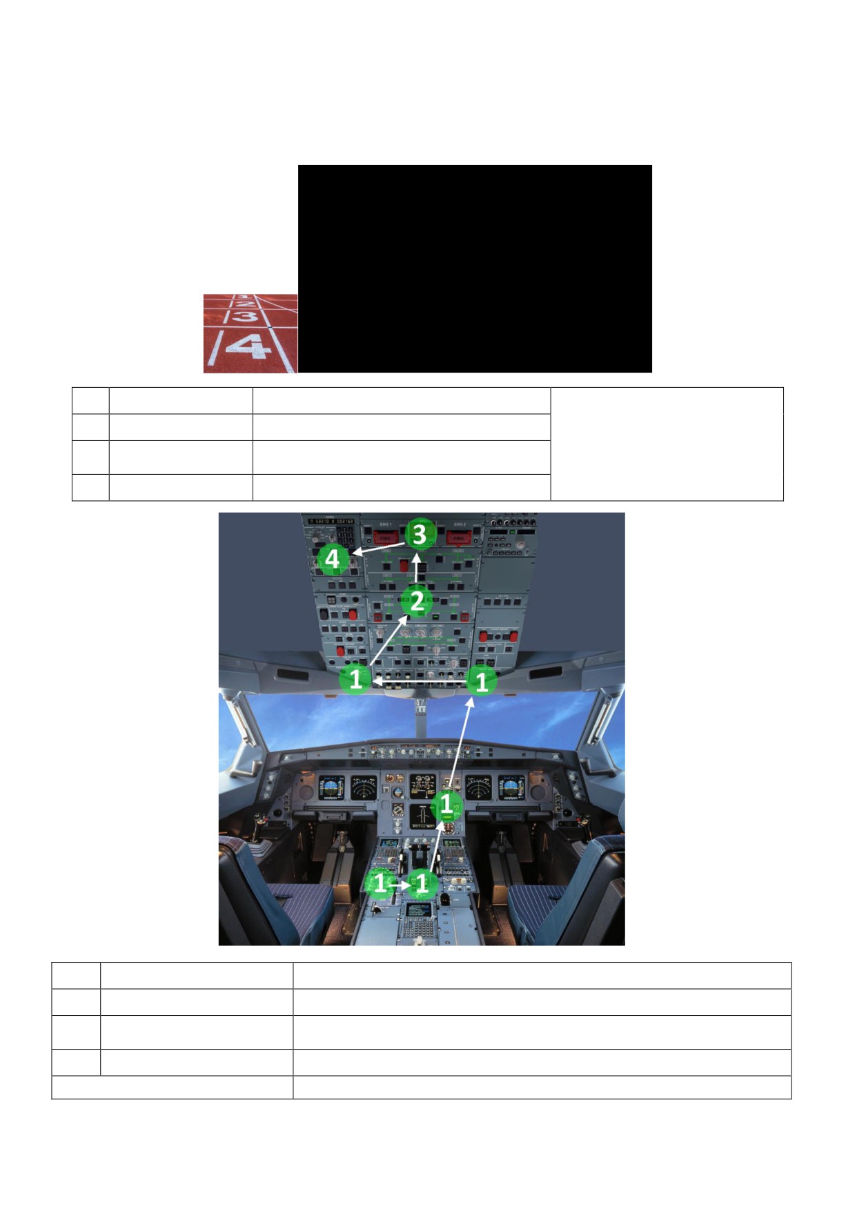
SAFETY EXTERIOR INSPECTION - CM2
• Wheel Chocks
• Landing Gear Doors
• APU Area
PRELIMINARY COCKPIT PREPARATION OVERVIEW
1
AIRCRAFT SETUP
Wx Radar, Engines, Landing Gear, Wipers
2
ELEC POWER
Battery Check & External power
CM2
RMP Setting
3
APU
Fire Test & Starting
4
ADIRS
Alignment
L
LIGHTS
CM1 + CM2
E
EFB
CM1 + CM2
Recall Warnings & Acceptance - CM1
A
ACCEPTANCE
TECH-LOG, MEL/CDL, QRH (A/C Config Summary, OEB) - CM1 + CM2
P
PERFORMANCE
Preliminary Takeoff Performance Calculation- CM1 + CM2
BEFORE WALKAROUND
PM
2

PRELIMINARY COCKPIT PREPARATION - EXPANDED
AIRCRAFT SETUP
Radar - OFF
WEATHER RADAR 1
This is the only step
Windshear / PWS- OFF
that is to be done in
Gain knob - AUTO/CAL
the transit checks.
Mode Selector - As Required
Masters Switch 1 and 2 - OFF
ENGINE
Mode Selector - NORM
LANDING GEAR
Lever - Down
WIPERS
Both Selectors - OFF
BATTERY CHECK & EXTERNAL POWER
• A/C Not Electrically Supplied for > 6 hours
¾ Batt Voltage Check 2
o Above 25.5 V - Batt 1,2 AUTO
ELECTRICS
o At or Below 25.5 V - Charge for 20 mins and check again 3
• A/C Electrically Supplied within < 6 hours
¾ Batt 1,2 AUTO 4
o EXT PWR ON if AVAIL light is on.
1. Procedures throughout this document refer to Collins WXR-1200. For Honeywell RDR-4000 (installed in some aircraft
like AP-BMX), please refer to the A320 Line Training Document.
2. Check batteries voltage with Batt Pb OFF.
3. Charge with Batt Pb on AUTO & EXT PWR ON. Check charging on ELEC page (i.e. battery contactor closed).
4. Batt voltage >25.5 ensures a charge above 50%. If APU is to be started on batteries then start within 30 mins of
putting Batt Pb on AUTO (delay of more than 35 mins can lead to battery charge of <25% of max capacity).
APU
• RMP
o Power - ON
o Nav Light - OFF
o SEL Light OFF
o FREQ - TUNE (communication frequencies)
• APU
o Fire Test - Perform 1
o Start - Perform 2
o Bleed - ON (temperature as required) 3
1. Automatic shutdown of APU & discharge of APU fire extinguisher bottle may occur if APU FIRE test pb is pressed for
more than 3 seconds. APU fire pb switch is lighted partially if AC power not available.
2. Use ground support & delay APU start. After master switch, wait 3s before selecting APU START pb. Keep external
power on to reduce APU load especially in hot weather. Follow LIM-APU-Start/Shutdown during refueling/defueling.
3. Do not use APU bleed with LP or HP ground air unit connected. To determine if HP ground air unit is connected,
check BLEED page to see if there is pressure in the bleed air system.
3
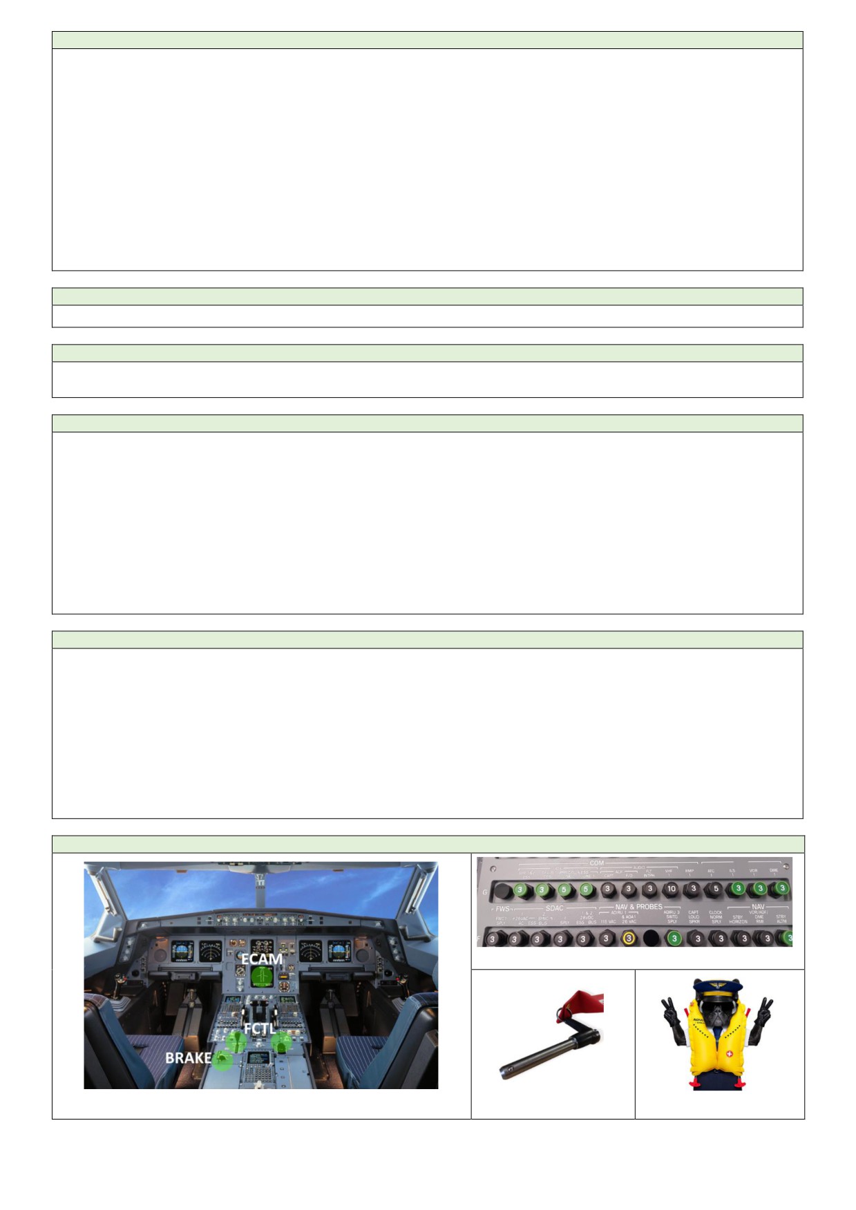
ADIRS
•
ALL IR Modes - SEL to NAV
•
A complete IRS alignment must be performed in the following cases:
o Before the first flight of the day, or
o When there is a crew change, or
o When the departure airport is located between latitudes 2 ° North and 2 ° South, or
o When the GPS is not available and the NAVAID coverage is poor on the expected route, or
o When the GPS is not available and the expected flight time is more than 3 hours.
•
A fast IRS alignment must be performed if:
o A complete IRS alignment is not necessary and
o Difference between IRS position & FMGC position is at or above 5 NM (Position Monitor Page).
LIGHT UP
•
Cockpit Lights - As Required
EFB
•
Version - Check
•
Initialization - Start
AIRCRAFT ACCEPTANCE
•
RCL - Push for 3 second to recall all cleared/cancelled warnings.
•
Technical Log - Check
•
MEL/ CDL - Check and activate in the performance application.
•
QRH:
o A/C Reg, MSN, Revision & Insertion Date
o OEB - Check
o A/C CONFIG SUMMARY - Check (Ops Data)
•
A/C Acceptance - Perform
•
In icing condition with OAT +3°C or below, check taxi-in time of the previous flight to determine the remaining
taxi-out time before next engine acceleration for ice shedding (PRO-NOR-SUP-ADVWXR).
PRELIMINARY PERFORMANCE
•
IPAD:
o Jeppesen FD Pro - Check Updated
o Fly Smart - Check Updated
o Digital Crew App:
Operator’s Data - EO SID Check Updated
Manuals - Check Updated
•
Airfield Data - Obtain
•
Preliminary Performance - Compare OPT vs CONF2 performance. If difference in TFLEX is < 3oC, select
higher flaps config. For short/badly paved runways - Higher Flaps. For better climb gradient - Lower Flaps.
•
NAV Charts - Prepare
BEFORE WALKAROUND
4

•
ECAM SD PAGES:
o ENG - Check Oil Quantity 1
o HYD - Check Reservoir Fluid Level 2
o DOOR - Check Oxygen pressure 3
•
FCTL: 4
o Flaps - Confirm Flap position agrees with the handle position.
o SPD Brake - Check retracted and disarmed.
•
Brakes:
o Parking Brake:
ACC Pressure - Check in Green 5
Parking Brake Handle - ON 6
Brake Pressure Indicator - Check Normal
o Alternate Brake - Check: 7
Yellow Elec Pump - Off
Chocks - On
Parking Brakes - Off
Brake Pedals - Press to Check Pressure on Brake Pressure Indicator 8
Brake Pedals Release - Parking Brakes ON
•
Emergency Equipment - Check 9
o Life Jackets
o Smoke Hoods
o Gloves
o Axe
o Portable Fire Extinguisher
o Oxygen Masks (goggles attached)
o Escape Ropes
•
CB Panels - Check:
o Overhead (49 VU)
o Rear (121, 122, 123, 124, 125 VU)
•
Landing Gear Pins - Onboard and Stowed
1. FCOM Limitations ENG OIL. Oil quantity >9.5qt + Estimated Consumption (approx. 0.5 qt/h).
2. Fluid volume may change with OAT and appear out of range w/o any low air pressure/level warning. Contact
maintenance in this case.
3. If half boxed in amber, refer to FCOM LIM-OXY Minimum Flight Crew Oxygen Pressure.
4. For a flight control surface/handle position disagree, check with maintenance before applying hydraulic power.
5. Use yellow electric pump to recharge if required. Yellow & Green systems required ground clearance before use.
6. With 1 brake > 500oC, or 350oC with brake fans ON, avoid parking brakes unless necessary. Parking brake must
be on for exterior inspection to check brake wear indicators.
7. Check before first flight of the day.
8. Pressure must build up without delay symmetrically on left & right sides for the same application simultaneously
applied on left & right pedals. With full pedal deflection, the pressure must be between 2000 and 2700 PSI.
9. Imagine yourself wearing a "Life Jacket" and a "Smoke Hood". Then putting on your "Gloves" with "Axe" in one
hand and "Fire Extinguisher" in the other. You then use the "Rope" to exit the cockpit to breath some fresh "Oxygen".
5
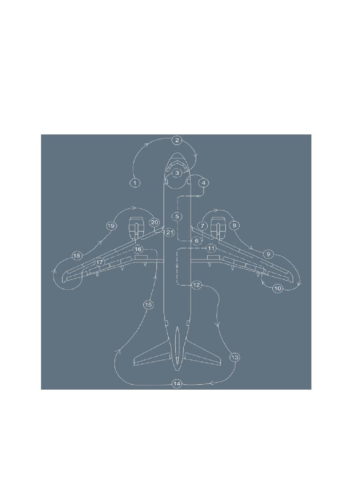
EXTERIOR WALKAROUND
Flight crew must perform a complete walkaround before each flight and ensure:
• General condition of the aircraft is satisfactory.
• Visible aircraft components and equipment are safe.
o No impact/damage to the structure.
o No evident fuel, oil, or hydraulic leak.
o All ground access doors are closed.
• Parking brake must be ON in order to check the brake wear indicators.
6
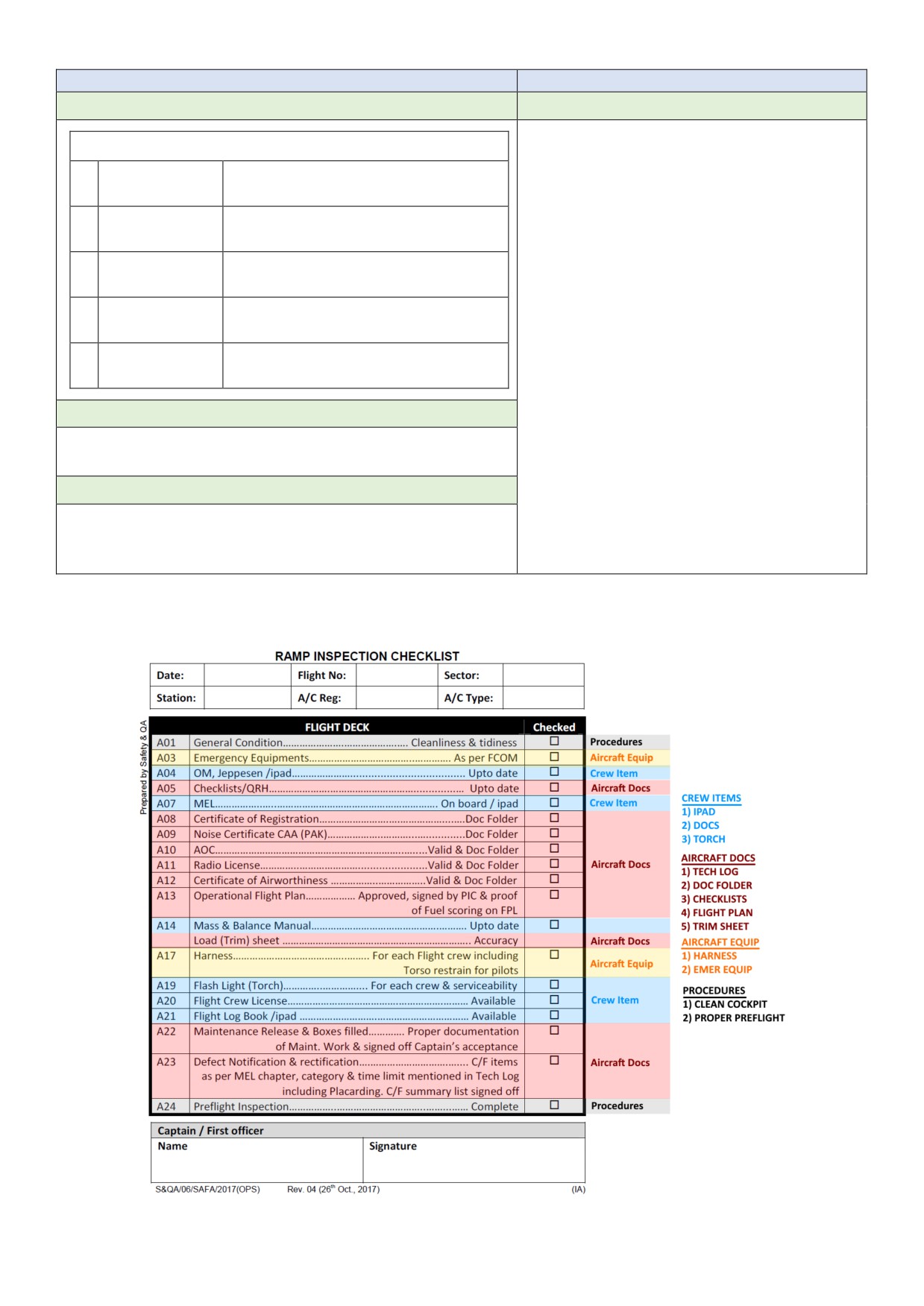
BEFORE BOARDING CLEARANCE
CM1
CM2
Man
Check
Cabin Crew Briefing
Aircraft Onboard Documents
A
Air Travel
Taxi & Flight Time, Routing, FL & WX.
• Certificate of Registration
• Certificate of Airworthiness
• Air Operator Certificate
B
Baggage
Baggage & seating related CG issues.
• Insurance Certificate
• Certificate of Radio Installation
C
Communication
Intercom, discrete code & cockpit door.
• Mobile Wireless License
• Weight Certificate
• Noise Certificate
D
Documents
Valid crew (cabin/cockpit) documents.
• RVSM Certificate
• IPAD Approval
E
Emergencies
Evacuation, emergency descent etc.
• Fuel Carnet
• Residual Disinfection Certificate
Machine
• Dent and Repair Chart
• Emergency Equipment Location Chart
• GACA Foreign Operator Authorization
• Technical Status
Other
Environment
• SAFA checklist *
• Misc. Blank Forms File
• Weather conditions
• Latest revision record (within 20 days)
• Cabin Status (temperature, catering etc.)
• Flight Pack List
* SAFA (Safety Assessment of Foreign Aircraft) CHECKLIST
7
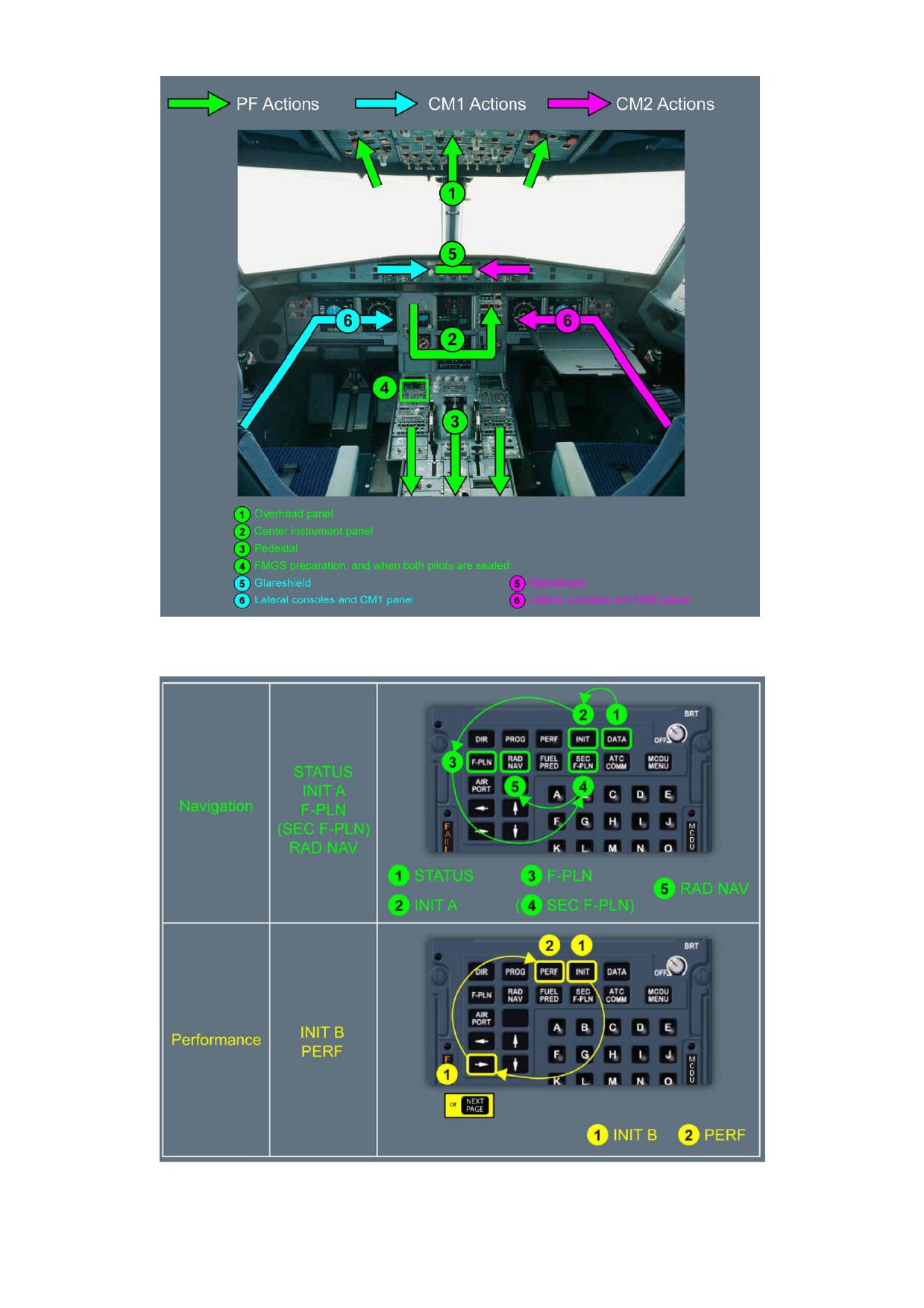
COCKPIT PREPARATION
8
•
A fast IRS alignment must be performed if a complete IRS alignment is not necessary and the difference between
the IRS position and the FMGC position is at or above 5 NM.
•
Pack Flow: LO if the number of occupants is below 141 and HI for abnormally hot and humid conditions.
•
BAT buttons OFF then ON to initiate a charging cycle. After 10 secs charging current should be < 60 A &
decreasing. If not, then after the end of the charging cycle perform this check again.
•
If center tank is < 200 kg for the flight and if affected by FUEL CTR TK PUMPS LO PR cautions the set FUEL MODE
SEL to MAN and CTR TK PUMPS to OFF. If the FUEL MODE SEL is unduly left in the MAN position on ground,
when CTR TK PUMPS or CTR TK XFR pb-sw are not in the OFF position then there is a possibility of fuel spillage.
Do not transmit on HF during refueling, defueling or fuel transfer. Only perform HF radio checks when appropriate
(i.e. no personnel in the immediate vicinity).
•
Third ACP PA knob on RECEPT allows CVR recording of cabin announcements. Set volume > medium range.
•
Use of the ISIS bugs function is not recommended.
•
If clock date is incorrect set it manually and keep the mode to internal (INT) for the whole flight. Clock date
initialization must be completed in less than a minute otherwise, CFDS will have to be reset by a maintenance
procedure in order to synchronize the lower ECAM time display with the cockpit clock display. For time precision
keep the clock in GPS or INT by syncing it with GPS at least once per day.
•
Insert the weights in FMGC after completing all other insertions to avoid cycles of prediction computations.
•
Thrust Reduction Altitude - 1000 feet AAL. Acceleration Altitude - 3000 feet AAL.
•
Cost Index - As mentioned in the flight plan. Keep a track of latest circulars.
•
Check the accuracy of tropopause value to ensure accuracy of FMS predictions.
•
Do not engage autothrust on ground, as it may generate the AUTO FLT A/THR OFF warning at engine start.
•
Note altimeter readings (QNH) on the CFP. Maximum altitude difference between:
o PFD and PFD = +20 feet.
o PFD and Elevation = +75 feet (RVSM tolerance).
o PFD and ISIS = + 100 feet.
•
To prevent hearing damage while performing oxygen mask test, inform ground crew connected to the intercom
system that a loud noise may be heard in the headset. After testing, check that there is no REGUL LO PR message
on DOOR/OXY page. Due to residual pressure between the LP valve and oxygen masks, an LP valve failed in the
closed position may go undetected during oxygen masks test. Absence of REGUL LO PR message ensures that
LP valve is open.
•
Check that CAB PRESS page displays LDG ELEV AUTO.
•
Check on STS page if INOP SYS display is compatible with MEL.
•
Check IRS alignment on POSITION MONITOR page. Distance between each IRS and the FMS position should be
lower than 5 NM. Confirm on ND aircraft position with that of airport, SID and surrounding NAVAIDs.
•
Releasing the parking brake prevents the critical structures from being exposed to high temperature levels for an
extended time. However, if operational conditions require (e.g., slippery tarmac), parking brake may remain applied.
9
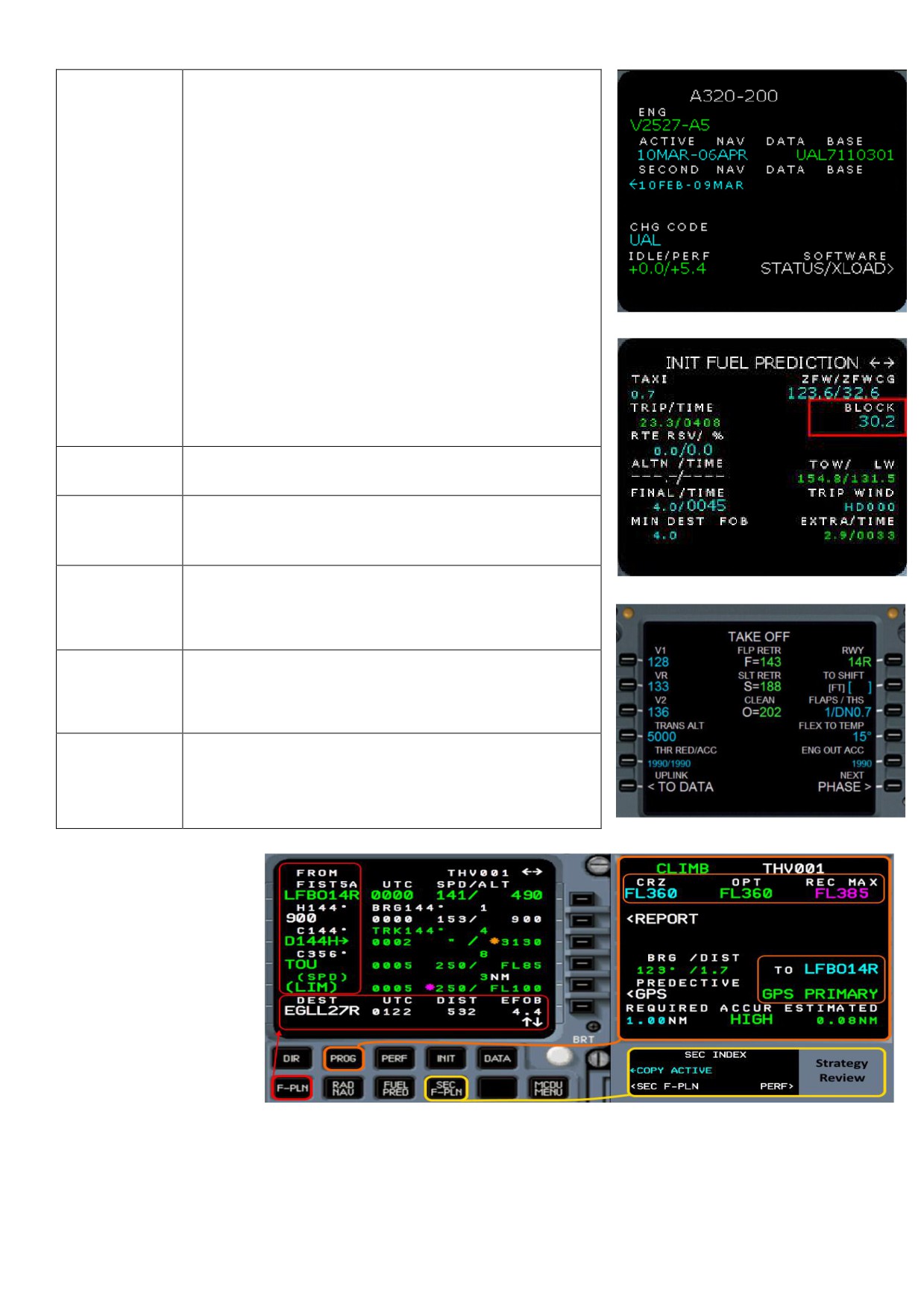
DEPARTURE BRIEFING 1
•
FMS
¾ DATA Page
Type and Model
APD & Nav Database Date
¾ FMS INIT- B Pag
Block Fuel (FOB on EWD)
Estimated TOW
Extra Time / Fuel at Destination
¾ PERF TAKEOFF Pag
AIRCRAFT
TO RWY
TO CONF
Flex / TOGA
V1, VR, V2
Transition Altitude
Thrust Reduction / ACC Altitude
¾ F-PLN & PROG Page
Route Waypoints
Time, Distance and Fuel
Strategy in secondary flight plan
WEATHER &
•
Weather reports and applicable procedures
NOTAMS
•
Applicable NOTAMS and procedures
•
ATC Procedures (push and start procedures)
STARTUP &
•
A/C Procedures (engine start etc.)
TAXI
•
Routing to the anticipated runway
•
Dimensions (Length, Width, Stopway)
•
Surface Condition
RUNWAY
•
Lighting
•
Packs / Anti ice - On/Off Takeoff
•
Normal SID - Routing and Constraints
•
Engine Out SID - Routing and Constraint
DEPARTURE
•
Navigation Frequencies to be used (RAD NAV)
•
MSA
•
NADP
•
Weather
SPECIAL
•
Terrain
PROCEDURES
•
Failures (Communication, Technical etc.)
•
Contingencies & Procedures - EO SID, DGR etc.
1. The main purpose of a
briefing is that all team
members should have the
same game plan to achieve
the target which in this case
is a safe flight from A to B.
The game plan in this case
comprises of:
a) Identifying threats.
b) Identifying deviations
from routine line operations.
c) Agreement on: “Actions to Mitigate Identified Threats” and “Strategies to Tackle Deviations”.
Instead of giving too much importance to “which crew (PF or PM)” will brief “which element” and losing the bigger picture,
it is important to keep the briefing interactive and in a logical sequence so that in the end everyone has the same mental
image regarding the game plan.
10