Airbus A320. AIRCRAFT CHARACTERISTICS AIRPORT AND MAINTENANCE PLANNING (2016-2023) - page 18

A320 INSTRUCTOR SUPPORT
NORMAL OPERATION
!
Operational Consequences
TASK SHARING
•
The task of each pilot is essential and complementary.
The PF supervises the approach (trajectory, attitude, speed) and takes appropriate decisions in case of
failure and/or at DH.
Since the approach is flown with AP/ATHR ON, the PF must be continuously ready to take over
if any AP hardover is experienced,
if a major failure occurs and
if any doubt arises.
•
The PNF monitors the following parameters
the FMA (LAND - FLARE - THR IDLE),
the Auto Call out,
the A/C trajectory or attitude exceedances. He will carry out the following call outs as per the table
hereunder:
the possible failures.
Parameter
Exceedance
Call out
IAS
VAPP - 5 / + 10 kt
Speed
V/S
> 1000 ft/mn
Sink Rate
Pitch
> 10° < - 2.5°
Pitch
Bank
> 7°
Bank
LOC
> ¼ dot
Loc
G/S
> 1 dot
Glide
- Exceedances and PNF associated call out -
•
The PNF state of mind is to be “Go Around Minded”.
Additionally the PNF takes care of ATC communication and applies the specific procedures associated to
CAT II / III operations.
•
The PF is usually the Captain (CM1) and PNF is the F/O (CM2).
FAILURES
In case a failure occurs during final approach there are three possible strategies:
-
continue the approach down to DH,
-
continue the approach to HIGHER DH or
-
Go Around.
In case of major failure during final approach, the following general rule applies:
-
if the failure occurs ABOVE 1000 ft, take appropriate action; continue the approach down to applicable
minima.
-
if some failures occur BELOW 1000 ft and ABOVE 200 ft, Go-Around unless visual. Those failures are:
one AP OFF, Capability degradation (triple clic), Amber cautions, Engine failure, Std by Attitude indicator
flag.
-
if those occur BELOW 200 ft, continue the approach.
-
if AUTOLAND red light comes up BELOW 200 ft, Go-Around. (2 APs OFF, LOC - G/S signal loss, LOC - G/S
excessive deviation).
-
if NO FLARE at 30 ft R/A, Go-Around unless visual.
NOTE:
If LAND green does not come up by 350 ft R/A, a Go-Around must be initiated. This is not a failure as such;
however it means that the AP is not properly stabilized at that altitude, which might cause guidance instability
lower and no proper autoland.
If ALPHA FLOOR is triggered below 1000 ft with no visual references, Go-around.
DATE: JAN 2001
Page 61
UDY0102

A320 INSTRUCTOR SUPPORT
NORMAL OPERATION
-
Some requirements are specific to CATIII with NO DH, because an Autoland is compulsory. These are not
necessarily monitored and thus not indicated.
• Incorrect ILS CRS (∆ 5° with runway CRS) leads to incorrect autopilot DECRAB.
Check ILS CRS at 350 ft. If incorrect, continue approach down to CAT II minima (AP must be set OFF at
80 ft latest).
• Nose Wheel Steering - Anti skid failure.
This will affect proper landing roll out function.
If failure ABOVE 350 ft R/A:
NWS failure
⇒ continue down to 50ft DH,
A/SKID failure
⇒ continue down to CAT II minima,
If failure BELOW 350 ft and ABOVE 200 ft
⇒ Go Around.
-
- The precision approaches are flown with AP/FD + ATHR ON. It is recommended to systematically set BOTH
APs ON even for CAT II or CAT III DH50 approaches.
In case ATHR goes OFF during the approach above 1000 ft:
-
try to set it back ON,
-
if only one AP is ON, set the other one ON and then try ATHR ON,
-
if ATHR is not recovered, only CAT II approach may be flown.
Always keep hands on thrust levers during final approach.
SUMMARY OF FAILURES AND CONSEQUENCES:
Failure
Action ABOVE 1000 ft
LANDING CATEGORY
1 Engine Out
ECAM procedure - Land CONF FULL
CAT III SINGLE
Loss of ATHR
Switch AP - Set ATHR back ON
CAT II if ATHR not recovered
NWS
N/A
CAT III SINGLE
(set AP OFF at touchdown)
A/SKID
N/A
CAT II
(set AP OFF at touchdown)
SLATS/FLAPS
N/A
CAT I
(set AP OFF at 500 ft latest)
2 R/A
Land in CONF 3
CAT I with raw data
1 PFD/1ND
Use switching to recover
CAT I if no recovery
Due to the loss of hydraulic redundancy.
REACHING DH
-
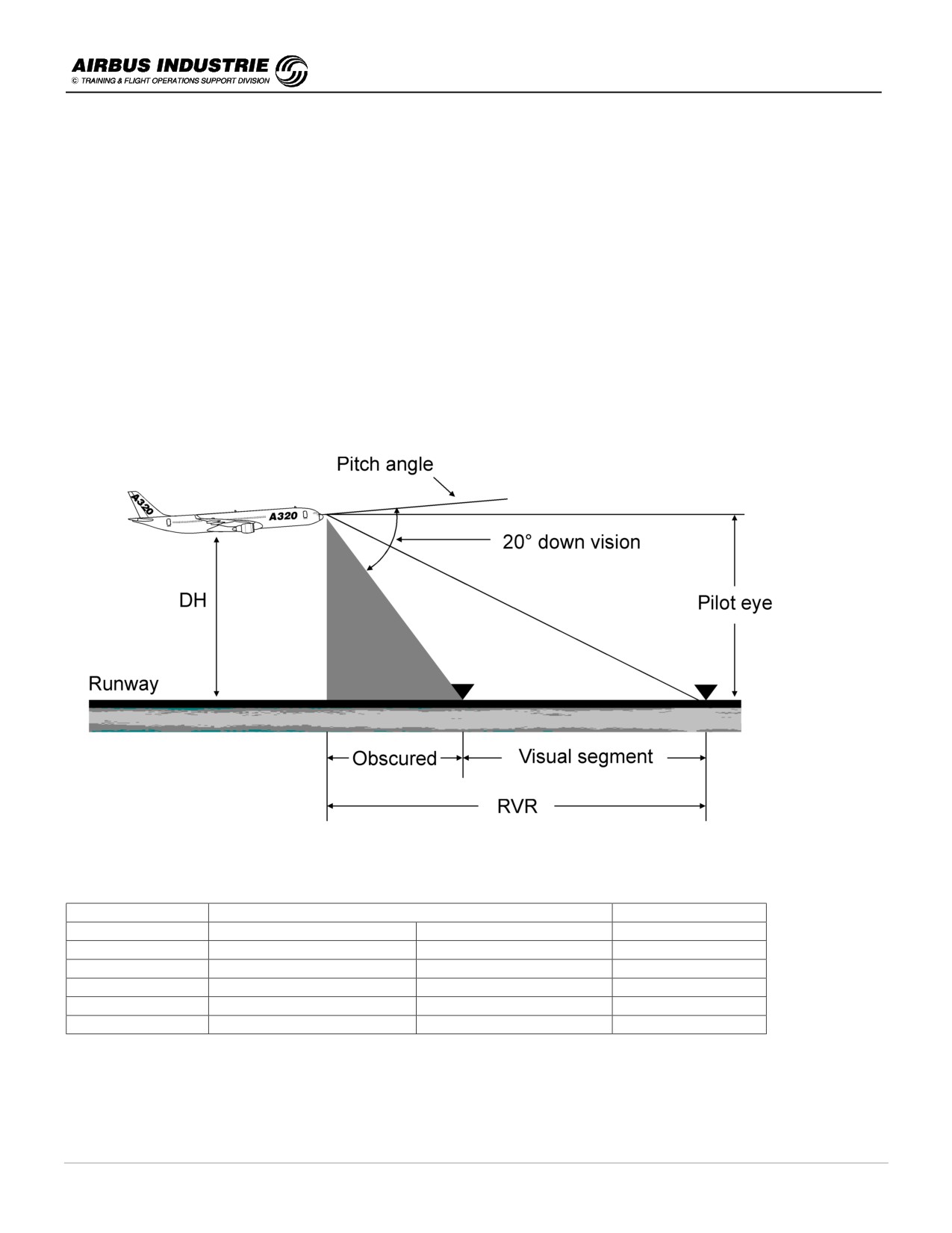
For precision approaches, DHs are lower than 100 ft and RVRs are very short. Therefore it is not easy for the
PF to get a good assessment of the A/C proper positioning versus the touchdown zone; and the time for this is
short.
• Before the approach initiation CAREFULLY adjust your seat position.
-
If no visual or if any doubt, Go Around immediately with NO ARGUMENTS
• Thrust levers TOGA
• Fly SRS FD Bars or AP
• Flaps retract on schedule.
In order to be ready mentally for Go Around, the CALL OUTs are essential; but for CATII approaches, the AUTO
CALL OUT is NOT mandatory; thus if not available the CALLOUT must be done by PNF.
For CATIII approaches, the AUTO CALL OUT is mandatory and has to be monitored by the PNF.
NOTE:
Actually in all cases of Autoland, Auto call out shall be available.
DATE: JAN 2001
Page 62
UDY0102
A320 INSTRUCTOR SUPPORT
NORMAL OPERATION
SOME SYSTEM PARTICULARS
-
The FMGS monitors its landing capability. If both APs are engaged, the capability displayed on FMA
corresponds to the LOWEST of both APs.
There is no capability degradation below 200 ft (alert height), due to the extremly low probability of a
second failure within the remaining time.
-
A capability degradation is shown on FMA enhanced by the triple click, and/or on ECAM (e.g. CATII ONLY) in
case of malfunction on following monitored systems:
AP - FD - ATHR - PFD - DMC - R/A - ILS - ADR/IR - ELAC/FAC - YAW DAMP, RUD TRIM - HYD - BSCU
channel - ELEC split - FWC - DH indication.
-
The AUTOLAND red light comes up on the glareshield if the aircraft is below 200 ft RA with at least one AP
ON, and one of the following event occurs:
• both APs trip off,
• excessive beam deviation is sensed (LOC above 15 ft, G/S above 100 ft),
• localizer or glide slope transmitter or receiver fails,
• a RA discrepancy higher than 15 ft is sensed.
But there are several other systems not monitored with regard to capability degradation (technical feasibility)
among others.
Window heat - Wipers - ND - VHF - A/SKID - NWS - AUTO CALLOUT - RUD TVL LIM - STD BY ATT (which must
be available in case of loss of main attitude indication to initiate safely a go around).
When AP is on with LOC - G/S engaged:
-
below 700 ft R/A, all data coming from the FMS are frozen (ILS tune inhibit, target speed etc.),
-
at 350 ft R/A, LAND must appear on FMA. This ensures that the remainder of the approach guidance will be
correct,
-
LAND might come below 300 ft R/A, which is too late; usually the triple click comes up before,
-
below 400 ft R/A, the FCU is frozen. Any action on FCU is disregarded by the FMGC (pressing AP - ATHR
P/Bs or change of modes etc.).
-
But the I/Ds on STICK and LEVERS are effective, regardless of Radio Altitude.
-
LAND mode can only be disregarded by Go Around (thrust levers on TOGA),
-
once A/C on ground, if thrust levers are set to TOGA, this engages SRS / GA TRK modes and sets APs to
OFF. This is usefull for Touch and Goes,
-
FLARE comes at or below 40 ft. THR IDLE at or below 30 ft R/A,
-
the RETARD AUTO CALL OUT is:
• at 20 ft R/A for manual landing, as an indication and
• at 10 ft R/A for autoland, as an order.
DATE: JAN 2001
Page 63
UDY0102
A320 INSTRUCTOR SUPPORT
NORMAL OPERATION
!
Landing / Roll out
- Although when LAND mode appears on FMA, this ensures that all is set for autoland, it is most recommended
that the PNF announces FLARE. The PF should then notice a pitch up reaction of the aircraft.
- During FLARE, Decrab and Roll out, the PF shall watch outside to assess that the maneuver is OK considering
the available visual references or if DH is very low, to achieve the visual references.
- Note that landing lights might be prejudicial to acquire visual reference.
- AUTO BRAKE is recommended; it ensures a symmetrical brake pressure application. However be aware of
possible dissymmetry in case of Xwind and wet runway.
- Select MAX REV when MLG is on ground; this triggers the Partial Lift Dumping (PLD) which ensures that both
MLG will be properly on ground.
- Monitor the ROLL OUT with the available visual references.
- Once the A/C is properly controlled (speed and lateral trajectory), PNF advises ATC.
- In case of CAT II, Autoland is recommended. If the PF takes over, he shall do it 80 ft R/A at the latest; this
ensures a good transition for the manual landing.
!
Reaching DH - Visual Segment and Minimum RVR (A320)
Height/Dist.
CAT III
CAT II
DH
15 ft
50 ft
100 ft
Pitch
5.4°
4.7°
4.7°
Pilot eye
36 ft
71 ft
121 ft
Visual segment
60 m
60 m
120 m
Obscured
43 m
79 m
134 m
Minimum RVR
103 m
139 m
254 m
DATE: JAN 2001
Page 64
UDY0102

A320 INSTRUCTOR SUPPORT
NORMAL OPERATION
!
Approach briefing associated to precision approaches before TOD
Considering all the specifics of Precision Approaches, the approach briefing will outline additionally to the standard
approach briefing:
-
the airport specific requirements,
-
the general task sharing strategy, and exceedance call outs and
-
the general strategy in case of failure (above/below 1000 ft).
!
Precision Approach Minima Reminder
Approach Category
ICAO
FAA
JAA
DH
100 ft ≤ DH < 200 ft
100 ft ≤ DH < 200 ft
100 ft ≤ DH < 200 ft
CAT II
350 m ≤ RVR
350 m ≤ RVR < 800 m
300 m ≤ RVR
RVR
1200 ft ≤ RVR
1200 ft ≤ RVR < 2400 ft
1000 ft ≤ RVR
DH
No DH or DH < 100 ft
No DH or DH < 100 ft
DH < 100 ft typic 50 ft
CAT III A
(single)
200 m ≤ RVR
200 m ≤ RVR
200 m ≤ RVR
RVR
700 ft ≤ RVR
700 ft ≤ RVR
700 ft ≤ RVR
No DH or DH < 50 ft
DH
No DH or DH < 50 ft
No DH or DH < 50 ft
typic 20 ft
CAT III B
(dual)
50 m ≤ RVR < 200m
50 m ≤ RVR < 200 m
75 m ≤ RVR < 200 m
RVR
150 ft ≤ RVR < 700 ft
150 ft ≤ RVR < 700 ft
250 ft ≤ RVR < 700 ft
No DH
No DH
CAT III C
No RVR limitation
No RVR limitation
Acceptable operational correspondance meter/feet (ICAO)
15 m
=
50 ft
150 m
=
500 ft
250 m
=
800 ft
500 m
=
1600 ft
30 m
=
100 ft
175 m
=
600 ft
300 m
=
1000 ft
550 m
=
1800 ft
50 m
=
150 ft
200 m
=
700 ft
350 m
=
1200 ft
600 m
=
2000 ft
75 m
=
250 ft
400 m
=
1400 ft
800 m
=
2400 ft
100 m
=
300 ft
1000 m
=
3000 ft
DATE: JAN 2001
Page 65
UDY0102

A320 INSTRUCTOR SUPPORT
NORMAL OPERATION
13 - VAPP DETERMINATION
!
VAPP in Normal Configuration
-
VAPP is defined by the crew to perform the safest approach; it is a function of GW, CONF, WIND, ATHR ON/OFF,
ICING, DOWNBURST.
-
VAPP is computed out of VLS (1,23 VS1G) of the landing configuration:
5kts for ATHR
VAPP = VLS + ∆ maximum of
5kts for severe icing
1/3 of STEADY headwind (max 15 kts)
-
In 95% of the cases the FMGC provides the valuable VAPP on PERF APPR page, once FLAP 3 or FLAPS
FULL landing configuration has been inserted, as well as tower wind:
VAPP = VLS + max
5kts, 1/3 tower wind component on landing RWY in the FPLN
Be aware that the wind direction provided by the Tower or ATIS is given in the same reference as the runway direction
(magnetic or true) whereas the wind provided by VOLMET, METAR or TAF is always true.
On PERF APPR, the FMS considers the wind direction to be in the same reference as the runway direction; therefore if
the airport is magnetic referenced, insert the magnetic wind direction.
NOTE:
VAPP is computed at predicted LW while the A/C is in CRZ, DES phases. Once in APPR phase, VAPP is computed
using current GW.
-
Can you insert a lower VAPP if no wind ? Yes, provided the landing is performed manually with ATHR OFF and
there is no ice or expected downburst.
-
Can you increase the VAPP manually ? Yes in case of a strong suspected downburst. In that case:
• VAPP = VLS + max 15 kts can be inserted.
NOTE:
In case of expected downburst, you might obviously envisage to delay landing or divert.
DATE: JAN 2001
Page 66
UDY0102
A320 INSTRUCTOR SUPPORT
NORMAL OPERATION
!
VAPP in Case of Abnormal Configuration (slats / flaps, flight controls etc…).
When a slats / flaps abnormal configuration occurs, the PFD displays a correct VLS related to the actual slats / flaps
configuration, except if both SFCCs have failed.
In some of these abnormal configurations, it is advisable to fly at a minimum speed higher than VLS to improve the
handling characteristics of the A/C. The ECAM then outputs the ∆VLS to be added to the VLS value displayed on
PFD, when the abnormal configuration is reached.
Hence VAPP will be ≥ VLS + ∆VLS → from ECAM
In order to prepare the approach and landing, the pilot needs to know VAPP in advance; but the VLS is not necessarily
available at that time on the PFD because the A/C flies at a higher speed or because the abnormal CONF is not yet
reached.
Hence VAPP will be determined using the QRH (2.25). The principle is to refer to VREF (VLS CONF full), which can be
read on PERF APPR or QRH, and to add ∆VREF from the QRH table.
VAPP = VREF
+
∆VREF
+ WIND CORR
➥ VLS CONF FULL ➥ from the table
∆VREF + WIND CORR is limited to 20 kts
Thus if ∆VREF > 20, there is no wind correction to apply.
!
Some consideration regarding GS mini guidance
-
As a general rule, use MANAGED SPEED in approach, in order to benefit from of the Ground Speed mini
guidance (GS mini) which assists the pilots in managing longitudinal shears, or severe gusts.
There are some exceptions to this rule in some abnormal configurations, dictated by the fact that the resulting
target speeds might be very high.
-
The purpose of the GS mini guidance in approach is to always keep the A/C energy level above a minimum
value, regardless of the wind variations or gusts - This minimum level is the energy the A/C will have at landing
with the expected tower wind; it is materialized by the ground speed of the A/C at that time which is called GS
mini:
GS mini = VAPP - Tower head wind component
In order to achieve that goal, the A/C GS should never drop below GS mini in the approach while the winds are
changing - Thus the A/C IAS must vary while flying down in order to cope with the gusts or wind changes.
In order to make this possible for the pilot or for the ATHR, the FMGS continuously computes an IAS target speed,
which ensures that the A/C GS is at least equal to GS mini; the FMGS uses the instantaneous wind component
experienced by the A/C:
IAS Target Speed = GS mini + Current headwind component
This target speed is limited by VFE-5 in case of very strong gusts, by VAPP in case of tailwind or if instantaneous
wind is lower than the tower wind; below 400ft, the effect of the current wind variations is smoothly decreased so
as to avoid too high speeds in the flare (1/3 of current wind variations taken into account).
DATE: JAN 2001
Page 67
UDY0102
A320 INSTRUCTOR SUPPORT
NORMAL OPERATION
The GS mini guidance has 3 major benefits:
1. It allows an efficient management of the thrust in gusts or longitudinal shears. Thrust varies in the right sense
but in a smaller range (± 15% N1) in gusty situations which explains why it is recommended in such situations.
2. It provides additional but rational safety margins in shears.
3. It allows pilots "to understand what is going on" in perturbed approaches by monitoring the target speed magenta
bugs: when it goes up = head wind gust.
The following schematic explains those advantages:
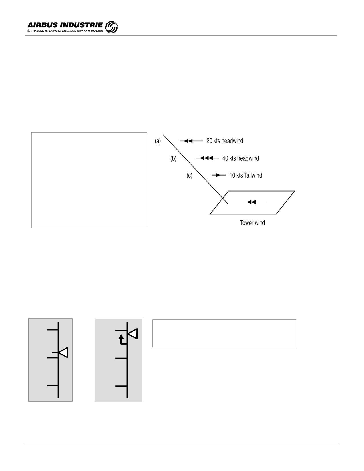
Suppose VLS = 130 kts
and the tower wind from
ATIS is 20kts (head wind component)
The FMGS computes VAPP:
VAPP = VLS + max (5, 1/3 Tower wind)
VAPP = 137 kts
Thus GS mini = VAPP - Tower wind
GS mini = 117 kts
The FMGS will therefore compute the IAS target speed = GS mini + current wind.
In the 3 cases of the schematic, we will read on PFD speed scale:
a) Target speed = 137 kts,
b) Target speed = 157 kts,
c) Target speed = 137 kts (because VAPP is the minimum value).
We can notice that in between a) and b) we have a front gust. We shall see on the PFD speed scale the target speed
going up from 137 kts to 157 kts, while simultaneously the speed trend arrow and the IAS will go up for obvious
aerodynamic consequences; the thrust will increase, but not excessively because of the speed trend already
experienced.
160
160
Head wind gust:
IAS and speed trend arrow go up, target speed
goes up and N1 smoothly increases.
140
140
a)
b)
120
120
DATE: JAN 2001
Page 68
UDY0102
A320 INSTRUCTOR SUPPORT
NORMAL OPERATION
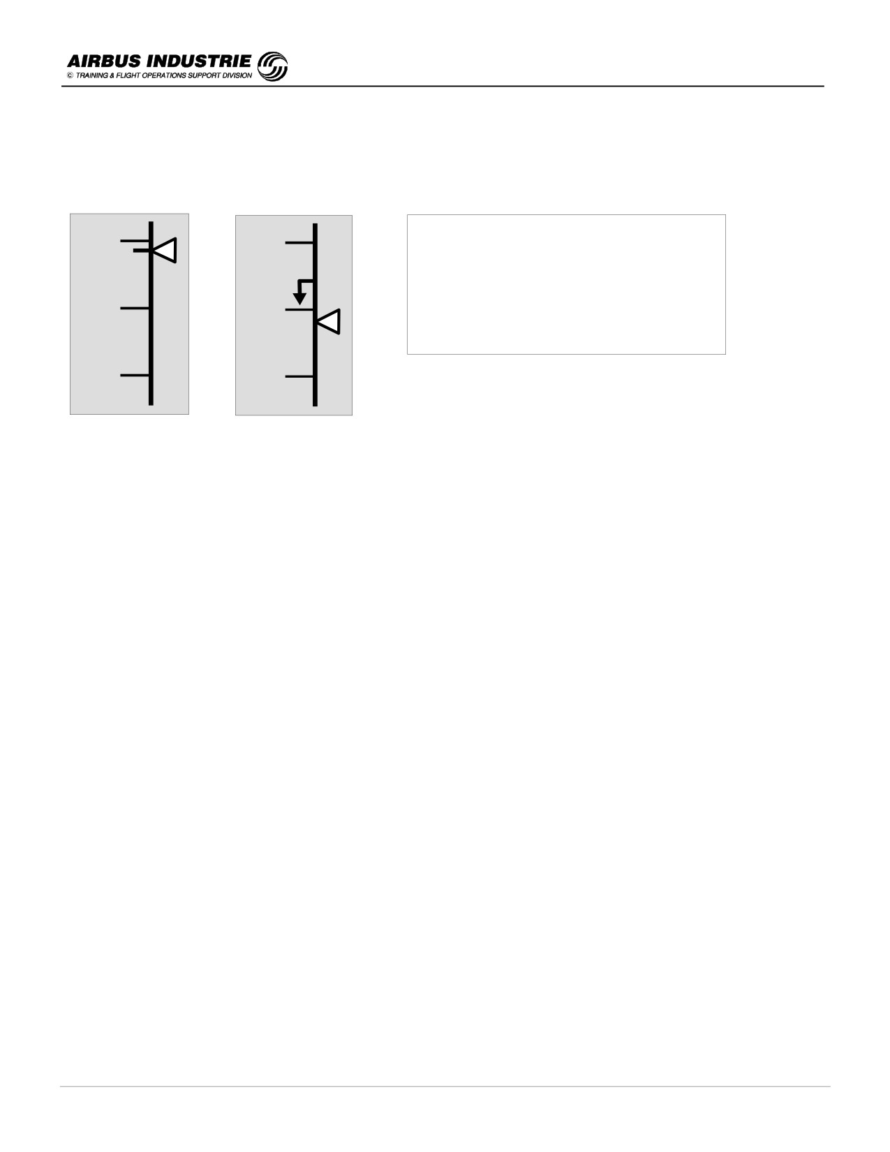
In case of a tailwind gust, which often follows a head wind gust in a shear, IAS and speed trend arrow go down, as well
as the target sped; N1 smoothly decreases - This is what happens in between b) and c).
160
160
Tailwind gust:
IAS and speed trend arrow go down, target
speed goes down and N1 smoothly
decreases.
140
140
Note that b) at the time of the tailwind gust,
the thrust was high which is safe.
b)
c)
120
120
NOTE:
• The ATIS and TOWER wind is a two minute average wind; gusts are considered if in the past 10 mn the peak wind
value exceeds by typically 10 kts or more the two minute average wind.
• The METAR is a ten minute average wind, with 10 minute gusts. It is always referenced to True North.
• The wind information used by the FMGS for the Managed Speed target control during the approach (GS mini
guidance) is provided by the onside IRS (update rate typically 10 times/sec); thus it is an instantaneous wind
information.
DATE: JAN 2001
Page 69
UDY0102
A320 INSTRUCTOR SUPPORT
NORMAL OPERATION
14 - LANDING, FLARE, ROLLOUT AND BRAKING
There are 3 steps in the landing: Flare / Touchdown / Rollout.
!
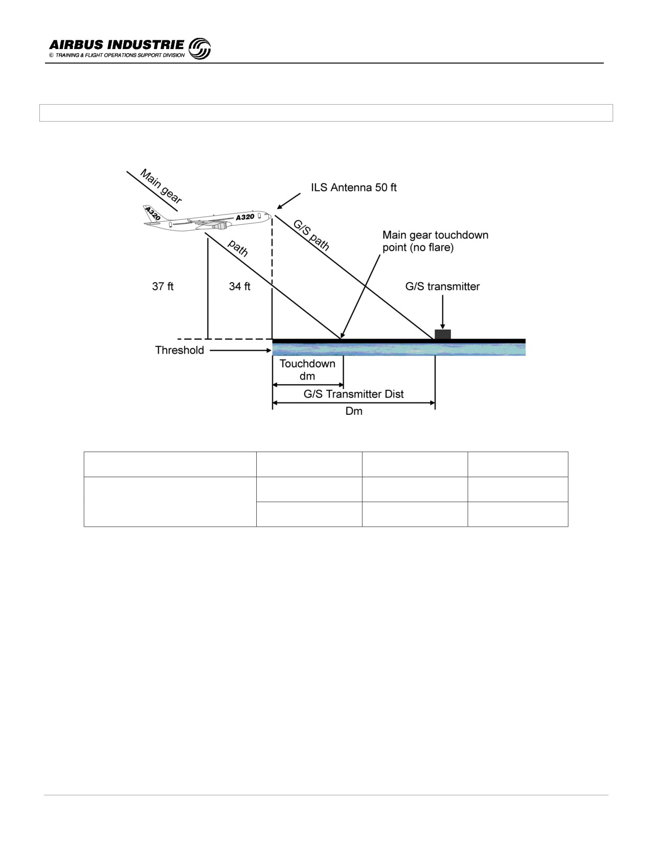
Aircraft Approach and Landing Geometry at 50 ft (A 320)
A/C conditions
G/S path
Dm
dm
A 319/A 320/A 321
A/C ILS antenna at 50ft
2°5
227 m
348 m
236 m/223 m
CONF FULL - Pitch ≈ 4° No flare
3°
187 m
291 m
198 m/182 m
The pilot eyes are approximately at 56 ft when crossing runway threshold.
!
Flare
-
Once AP is set to OFF using the Instinctive Disconnect button on the stick either on short final or in the flare,
be smooth on the stick. The A/C is stable.
If you feel that you are very ACTIVE on the stick, release it; the A/C will stabilize.
-
When transitioning from IMC to VMC, watch the BIRD position versus the A/C attitude symbol in the center of
PFD; this gives a good assessment of the drift, thus in which direction to look for the runway.
But then:
- don’t turn towards the runway,
- don’t duck under.
-
The final approach with crosswind is conducted flying the aircraft track to the runway centreline, i.e. applying a
drift correction. This is a "crabbed approach" with wings level.
DATE: JAN 2001
Page 70
UDY0102
A320 INSTRUCTOR SUPPORT
NORMAL OPERATION
FLARE ITSELF
-
When reaching 50 ft RA, the pitch law is modified to flare mode: indeed, the normal pitch law which provides
trajectory stability is not the best adapted for the flare maneuver. The system memorizes the attitude at 50 ft,
and that attitude becomes the initial reference for pitch attitude control. As the aircraft descends through 30 ft,
the system begins to reduce the pitch attitude (2° down in 8 sec). Consequently as the speed reduces, the pilot
will have to move the stick rearwards to maintain a constant path. The Flare technique is thus very
conventional.
Feedbacks and static stability augmentation are removed on ground.
The roll is a roll rate law till the A/C is on ground.
-
Start the Flare at around 20 ft; it is a progressive aft action on the stick. A continuous aft pressure has to be
applied as usual.
-
At 20 ft a call out « RETARD » reminds the pilot to retard thrust lever. It is a reminder, not an order. Indeed with
ATHR ON, SPEED mode is effective except if autoland (AP ON with LAND/FLARE). Therefore if you are late to
retard the thrust levers in a MANUAL landing, the ATHR will add thrust during the Flare to keep the A/C on
target speed.
-
In order to assess the Flare and the A/C position versus the ground, look out well ahead of the A/C.
-
However if PITCH > 10°, PNF shall announce it.
-
The typical pitch increment in Flare is approximately 4° which leads to a
- 1° flight path angle associated to a
10 kts speed decay in the maneuver. These are « typical » figures.
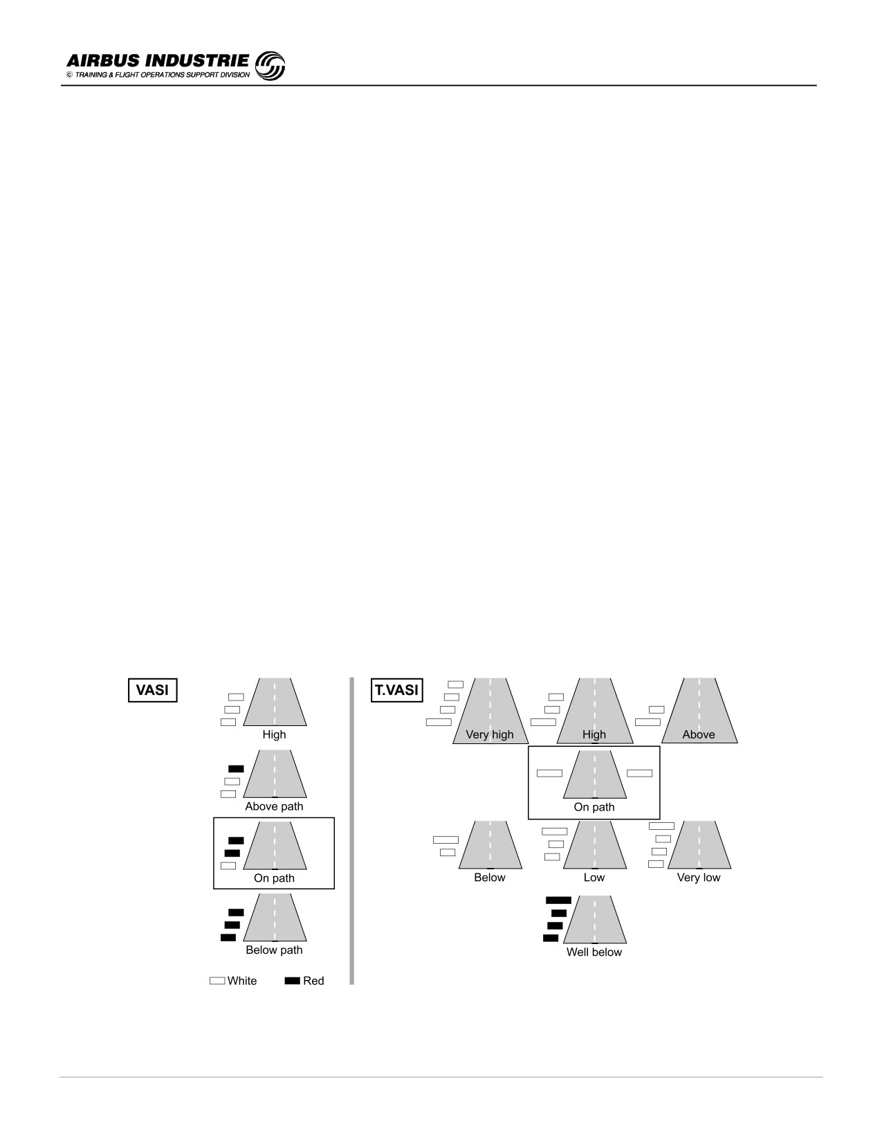
VASI - TVASI - PAPI approach slope / path indicators
VASI and TVASI are providing the crew with an aim point located adjacent to the installation, as well as a mean to
stabilize the aircraft on a proper constant visual approach path.
The boxed displays are to be used in approach. They ensure a wheel clearance above threshold of about 20
feet, on the A320 family.
DATE: JAN 2001
Page 71
UDY0102
A320 INSTRUCTOR SUPPORT
NORMAL OPERATION
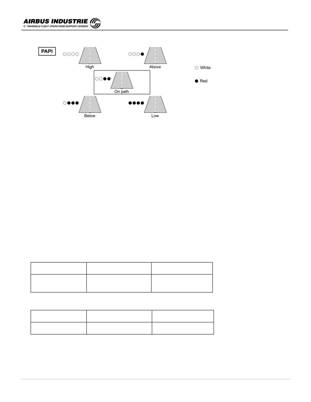
PAPI is aligned with a G/S path. As the VASI it provides an aiming point adjacent to the installation, and
materializes a constant visual approach path to assist the pilot in the visual part of the approach.
ICAO requirements specify that PAPIs should be positioned such that Minimum Eye Height over Threshold
(MEHT) gives adequate wheel clearance for aircraft which are regular users. Thus, for each runway PAPI are
adjusted so as to provide adequate wheel clearance to regular user aircraft.
MEHT is not easily accessible to pilots; they are only on national publications.
On the A320 the eye to wheel height is approximately 25 ft and the minimum wheel clearance over threshold is 20
ft. Thus a PAPI may be followed below 200 ft on A320 provided the MEHT > 45 ft.
!
Avoiding Tailstrike (refer to FCOM bulletin N°22)
-
Deviation from normal landing technique is the main cause of tailstrike at landing:
• too high speed drop below VAPP (pitch up to avoid high sink rate),
• prolonged hold off to do a « kiss » landing,
• flare too high and
• no control of the de-rotation once the A/C is on ground.
-
Once the A/C closes up the ground and touches, there are factors which increase the tendency of pitch up
such as the ground reaction itself at aft C.G., the ground spoilers deployment. Smoothly control the de-rotation.
Typical values of ground clearance in pitch:
A/C
Pitch with Ldg Gear
Pitch with Ldg Gear
compressed
extended
A 319
13.9°
15.7°
A 320
11.7°
13.7°
A 321
9.7°
11.4°
Typical values in bank for wing tip or engine scrape:
A/C
Bank with Ldg Gear
Bank with Ldg Gear
compressed
extended
A 319/A 320/A 321
16°
18°
CROSSWIND LANDING
-
During the Flare, the roll normal law is still effective. Thus when the pilot applies a RIGHT rudder pedal input
for example, the aircraft yaws and rolls to the RIGHT; but it stabilizes with a steady bank angle. The more
pedal input there is, the more induced yaw and bank there is with stick free. The aircraft will then turn gently to
the right.
DATE: JAN 2001
Page 72
UDY0102
A320 INSTRUCTOR SUPPORT
NORMAL OPERATION
-
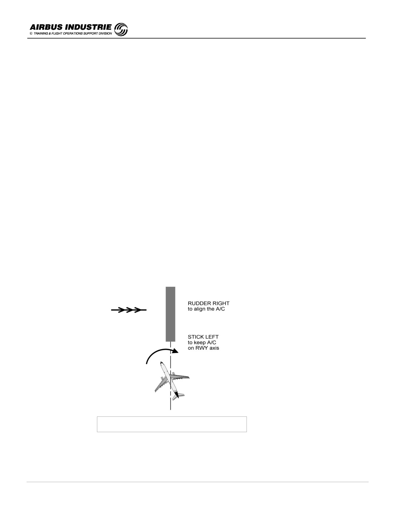
If the A/C comes for landing with wind from the LEFT, and if the pilot wishes the A/C to land with the fuselage
aligned with runway center line, he has to apply some rudder to the RIGHT. Thus, if he does not act laterally
on the stick, the A/C will turn to the right because of the resulting bank angle and because of the effect of the
wind.
In order to keep the A/C on the runway center line, the pilot will have to apply some stick to the left.
-
Hence the recommended technique for crosswind landing is:
• apply rudder to align the A/C on runway center line and
• act on the stick (on the opposite direction) to maintain the A/C on the center line, with possibly very slight
wing down into wind.
NOTE:
In strong crosswind, a full decrab might lead to a significant into wind aileron input causing a significant bank angle.
The pilot must be aware that there are aircraft geometry limitations in pitch and in bank not only to prevent incurring a
tailstrike but to prevent scrapping the engine pod, the flaps or the wing tip.
In such conditions, a partial decrab is preferable.
Example: with 30kt crosswind, a full decrab leads to 10° bank angle, whereas a partial decrab (5° crab angle
remaining) requires only 5° bank angle.
NOTE:
The Maximum Demonstrated Crosswind (maximum encountered crosswind component during flight test) is published
in the AFM. It is not an operating limitation (unless stated); it applies to a steady wind and does not necessarily reflect
the maximum capability of the aircraft.
A Maximum Computed Crosswind reflects the aircraft capability in terms of rudder, roll and wheel cornering capability.
DECRAB TECHNIQUE WITH CROSS CONTROLS
DECRAB TECHNIQUE = CROSS CONTROLS
NOTE:
Once on ground avoid putting stick into wind, for better steering efficiency.
DATE: JAN 2001
Page 73
UDY0102
A320 INSTRUCTOR SUPPORT
NORMAL OPERATION
!
Derotation, roll out and braking
•
Derotation
-
When the A/C is on ground, pitch and roll laws are basically direct.
-
As a consequence, when the A/C touches down, the pilot has to fly the nose down gently by maintaining a
slight aft pressure on the stick to slow down the de-rotation movement.
-
When the A/C touches down with at least one Main Landing Gear and when at least 1 thrust lever is in the
reverse sector, the ground spoilers partially automatically deploy to around 10° to ensure that the A/C will
properly sit down on ground. Then the ground spoilers automatically fully extend. This is the Partial Lift
Dumping function (PLD).
-
It is not recommended to keep nose high in order to supposedly increase the aircraft drag during the initial part
of the roll out; this technic has a poor efficiency. Furthermore it leads the pilot to delay full thrust reverser
application as well as brake application. Finally, it increases the potential of tailstrike.
•
Roll out
-
During the Roll out, use the rudder pedals to steer the aircraft on the runway centreline; initially the rudder
will ensure the steering function at high speeds, and below around 100 kts the Nose Wheel Steering function
commanded by the pedals will take over.
-
In case of crosswind various precautions need to be considered:
* Avoid deflecting the stick into wind. It has practically no efficiency, but adverse side effects on braking.
Indeed, it creates a differential down force on the wheels into the wind side due to the aileron deflection,
and it creates a differential drag effect due to spoiler retraction on the out of wind side. These differential
effects favors the "natural into the wind" turn tendency of the aircraft.
* The reversers have a destabilizing effect on the airflow around the rudder and thus decrease the
efficiency of the rudder. Furthermore, it creates a side force, in case of a remaining crab angle, which
increases the lateral skidding tendency of the aircraft. This adverse effect is quite noticeable on
contaminated runways with crosswind. In case a lateral control problem occurs in high crosswind landing,
consider to set reversers back to Idle.
* In lower speeds, the directional control of the A/C is more problematic, more specifically on wet and
contaminated runways. Differential braking is to be used if necessary. On wet and contaminated runways,
the same braking effect may be reached with full or half deflection of the pedals; additionally the anti skid
system releases the brake pressure on both sides very early when the pilot presses on the pedals.
Thus if differential braking is to be used, totally release the pedal on the opposite side to the expected turn
direction.
DATE: JAN 2001
Page 74
UDY0102
A320 INSTRUCTOR SUPPORT
NORMAL OPERATION
•
Braking
A proper braking technic will minimize the landing distance.
However there are many factors during final approach which affect the landing distance and reduce some
of the regulatory margins built in the minimum required distance for landing:
- factors increasing the TAS at landing:
airport elevation 1000 ft, and/or QNH 980 hPa adds 10% to actual landing distance
- a 10% excess in approach speed, adds some 20% to actual landing distance
- a 50 ft excess in altitude at runway threshold (i.e. flying 100 ft at runway threshold) adds some 300 m
to the actual landing distance.
- a long flare may add to some 30% to actual landing distance (typically to bleed a 5% excess in
approach speed).
Thus a properly stabilized approach on path and on speed is essential for a proper landing as
well as to minimize landing distance.
What are the systems, once the aircraft is on ground, which participate to the braking?
These are the Ground Spoilers, the Reversers and the brake on wheels:
-
the Ground Spoilers have three effects: they contribute to the aircraft deceleration by aerodynamic
drag, they increase considerably the wheel braking efficiency by increasing the load on the
wheels and in case of Autobrake selected, they allow the autobrake to function (A/Brake triggered by
Ground Spoiler extension signal).
In terms of aerodynamic drag, the ground spoilers are efficient at high speed and participate to some
30% in the landing distance.
-
the thrust reversers have a significant braking efficiency at higher speeds, say down to 70 kts, below
which their efficiency drops rapidly; their efficiency is independent from the runway condition.
The Maximum reverser thrust is obtained at N1 between 70% to 85%; it is not necessary to go higher
because no additional drag is obtained.
Below typically IAS 60 kts, there is a risk of engine stall; this is why it is recommended to smoothly
bring the reverser thrust to Idle at around this speed. However, it is allowed to keep Maximum
Reverser thrust down to aircraft stop, in emergency situation.
-
From touchdown to Maximum Reverse thrust available, it takes typically between 6 sec to 14 sec
(selection of Max Rev at MLG touchdown, or at NLG touchdown). Thus, in case Auto Brake is used,
the participation of the reverser in landing distance varies with the A/Brake deceleration rate selected:
* if MED is selected (.3 g or 6 kts/sec), the brakes takes the major part in braking contribution and the
reverser some 10% to 15%.
* if LO is selected (.15 g or 3 kts/sec), the reversers take some 25% in braking contribution.
-
Finally the Actual Landing distances demonstrated in flight test and provided in FCOM/QRH do not
include the use of reversers (which constitute a safety margin).
-
the wheel brakes are obviously the main actors in aircraft deceleration on ground; the brake force from
wheels are a function of:
* the force on tires due to load on wheels,
* the brake coefficient,
* the contact area of the tires with the runway,
* the friction coefficient between the tires and the runway.
DATE: JAN 2001
Page 75
UDY0102

A320 INSTRUCTOR SUPPORT
NORMAL OPERATION
Thus the braking efficiency depends upon the A/C speed, the load on wheels, the wheel speed (free
rolling, skidding or locked wheels), the runway condition but also the brake temperature and wear.
The antiskid system maintains the skidding factor close to the point providing maximum friction force; with
full pedal braking with anti skid the typical deceleration rate is 10 kts/sec (or .5g).
The brake efficiency depends upon the brake temperature despite the fact that carbon brakes are tolerant
to thermal overloads and maintain maximum torque capability at high temperatures. A BRAKE HOT
warning comes up so that the temperature in the middle of the brakes is below the hydraulic fluid
ignition point, typically 400° C. The indicated brake temperature is provided by sensors located close to
the brakes but not inside the brakes; this is why the BRAKE HOT message comes up at 300°C.
BRAKE HOT WARNING PURPOSE IS TO PREVENT FIRE
AFTER L/G RETRACTION IN CASE OF HYD FLUID LEAKAGE
Thus the proper use of all braking means at landing and during subsequent taxi, as well as proper use of
brake fans will allow minimizing turn around time: indeed the minimum turn around time ensures that the
brakes will cool down sufficiently so as to have the capability to absorb the energy built up during an RTO,
should it occur during the next T/O; in other words, the cool down will be sufficient so that no BRAKE HOT
warning will be triggered during the next taxi for T/O.
Brake fans will therefore be used after the landing roll to cool down the brakes after a significant braking
action. The indicated temperature will drop faster than the actual brake temperature, because of the sensor
location (typically indicated temp 150°, actual brake temp 300°). The brake fans must not be used during T/O
roll or landing roll in order to avoid deterioration. After landing, it is advisable to select them on when brake
temperature rises and the aircraft reaches the gate to avoid thermal oxidation of the brakes.
When reaching the gate, if there is a significant difference in brake temperature between the wheels of the
same gear, this materializes a potential problem with brakes: e.g. if one wheel reaches the limit temperature
of 600° while all other wheels indicate less than 400° to 450°, this indicates that there is a potential problem
of brake binding/or permanent brake application on that wheel. If, on the contrary, one wheel is at or below
60° C whereas the others are beyond 200°, this indicates that there is a potential loss of braking on that
wheel.
The brake wear is a factor affecting braking efficiency more specifically in case of RTO: indeed the maximum
energy which can be absorbed by a brake is proportional to the weight of its heat sink. With Carbon brakes,
the wear is directly linked to the number of pedal applications; pressing the pedals and modulating the
pressure without releasing the pedals is therefore a recommended technic for minimizing the brake wear.
You may use either pedal braking or Auto Brake; Auto Brake may be used in LO or MED for landing, MAX is
used for RTO. It controls a given deceleration rate (.15g and .3g). The DECEL light indicates that the
selected deceleration rate is or is not achieved, irrespective of the functioning of the autobrake. For
example, DECEL might not come up when A/Brake is selected on a contaminated runway because the
deceleration rate is not reached with the A/Brake properly functioning, whereas DECEL light might come up
with LO selected on Dry runway while the only reversers achieve the selected deceleration rate without
A/Brake being actually activated (in other words DECEL light is not an indicator of the A/Brake operation as
such or not, but that the deceleration rate is reached).
The Autobrake minimizes the number of brake applications thus the brake wear; therefore, except for those
cases where A/Brake selection is strongly recommended, it is up to the Captain's discretion to select it,
whenever he foresees a significant need for wheel brake application.
DATE: JAN 2001
Page 76
UDY0102
A320 INSTRUCTOR SUPPORT
NORMAL OPERATION
•
Overall recommendations for the ground phase:
-
Always Arm the ground spoilers.
-
Use A/Brake on Short, or on Wet & Contaminated runways, if poor visibility or with Autoland. MED is
recommended.
Selection of A/Brake is left at Captain's discretion in other cases; more particularly when significant need of
wheel brake application is foreseen (brake wear consideration).
-
Smoothly fly down the aircraft derotation.
-
During Roll out, track the runway centreline using the rudder pedals but not the tiller.
In case of crosswind:
* Avoid stick into wind.
* Be aware that Max Reverser thrust might laterally destabilize the aircraft.
* On wet or contaminated runway, differential braking might be necessary; release totally the pedals on the
opposite side to the expected turn direction.
-
At MLG touchdown, select REVERSER IDLE and once NLG is on ground, select MAX REVERSER, unless
required earlier. Don't wait the REV green indication on ECAM to pull for MAX REVERSER.
Reaching typically 70 kts, set gently reversers back to IDLE REVERSER and keep it IDLE till taxi speed is
reached.
In emergency situations, MAX REVERSER may be considered till aircraft stop.
-
In case of A/Brake use, select LO or MED for landing.
Monitor the DECEL light on the A/Brake panel; be aware that DECEL light merely indicates that the intended
deceleration rate is achieved.
On wet and contaminated runway, in case of uneven contamination, the A/Brake might destabilize the aircraft
laterally; consider deselecting it.
-
In case of PEDAL BRAKING, press on the pedals once the NLG is on ground unless earlier required. In order
to minimize brake wear, press on the pedals and modulate the pressure as required without releasing.
-
Select BRAKE FANS once taxi speed is reached; at the earliest but not prior to landing (to avoid
deterioration of those fans); to avoid thermal oxidation, it may be delayed till at the gate.
-
Reaching the gate, check the brake temperature and report any major difference in between two brake
temperatures.
DATE: JAN 2001
Page 77
UDY0102

A320 INSTRUCTOR SUPPORT
NORMAL OPERATION
•
Landing distances in QRH
-
The actual landing distance published in FCOM and QRH (4.0) is the certified landing distance demonstrated
using manual landing technique, ground spoilers and full pedal braking from touch down to complete A/C stop,
but with no reverser. Therefore there is quasi no margin in the actual landing distance to stop the aircraft within
that distance, to the exception of the marginal effect of the reversers: in order to take into account runway
slope, temperature effect, landing speed uncertainties, runway wet conditions… the regulations define an
adequate coefficient to determine the "required landing distance” (or minimum required runway length) at
destination or alternate out of this actual landing distance.
Therefore the actual landing distance is used for two purposes:
* For aircraft dispatch, in order to determine the "required landing distance" at destination, which
represents the minimum runway length required for landing at destination.
* In flight, in case of landing in abnormal configuration, in order to determine the additional amount of
landing distance caused by this situation. The multiplicative factor determined in the QRH is to be applied
to the actual landing distance CONF FULL.
-
The Landing distances in autoland with Auto brake is to be used in flight in case of diversion or in case the
crew wishes to assess the landing distance at destination in case of wet & contaminated runway conditions for
example. Those distances are indeed determined in autoland with A/Brake LO and MED; thus the flare phase
is close to what an airline pilot will manually fly and the braking technic is more representative of the airline
pilot braking technic, than full pedal braking at touchdown as done in certification flights.
In case of a diversion, if autoland is expected with a failure affecting the landing distance, the resulting landing
coefficient factor is to be applied on the Actual Landing distance determined with manual landing technic, but
not on the landing distance determined in autoland.
GOOD LANDING IS ENSURED AFTER A PROPERLY STABILIZED APPROACH
ON PITCH, ON PATH, ON SPEED
OPTIMUM LANDING DISTANCE IS OBTAINED BY ADEQUATE USE OF BRAKING MEANS:
GND SPOILERS, REVERSERS, AUTO/MANUAL BRAKING
NOTE:
As a rule of thumb, if the aircraft flies above runway threshold at MLW:
-
at too high speed: + 10 kts, landing distance increased by 200 m
-
too high altitude: + 50 ft, landing distance increased by 300 m
-
with ground spoilers not armed, landing distance increased by 250 m
-
if runway wet, multiply landing distance by 1.3; if compacted snow, by 1.7; if slush, by 2; if icy, by 3.5…
These are typical values.
DATE: JAN 2001
Page 78
UDY0102
A320 INSTRUCTOR SUPPORT
NORMAL OPERATION
!
Shutting down the engines - Potential of Tail Pipe Fire
-
When the aircraft taxies back to the gate, the crew must respect a minimum time required on certain engines
between landing (use of reverser) and engine shut down.
-
A tail pipe fire may occur at engine shutdown (as well as engine start), due to an excess of fuel in the
combustion chambre or an oil leak in the LP turbine race.
The excess fuel results either from an overfuel command by the FADEC or from a rotating stall, or from a
malfunctioning ignition system (or from a second engine start). This excess fuel ignites in the combustion
chambre with the engine rotating too slowly; it leads to an INTERNAL fire within the engine core or some
fuel burn in the aft LP turbine race; this fire is contained within the engine and has a minimum risk to develop in
an engine fire.
The oil which burns a "lazy fire" in the aft LP turbine race, comes at the time where an engine is shutdown
with no sufficient time running at idle; there is no significant risk of hazard for the engine, but a considerable
dense, black then white smoke develops out of the engine.
-
Thus in case of reported Engine Tail Pipe Fire:
-
Shutdown the Engine with Engine Master Switch (do not use the Eng Fire P/B, neither Engine fire
extinguishing bottles).
-
Crank the engine using either opposite or APU bleed, or external pneumatic power.
NOTE1:
Shutdown then crank actions:
ENG MASTER OFF / AIRBLEED PRESS ESTABLISH / ENG MODE SEL CRANK / MAN START ON.
The start valve automatically reopens when N2 > 20%.
NOTE2:
Extinguishing the Engine with the Eng Fire P/B prevents the possibility of engine cranking. The engine fire
extinguishing bottles spray the agent so as to extinguish the fire in the nacelle compartment; the agent does not reach
the LP turbine and does not extinguish a fire in the combustion chambre.
NOTE3:
If a tail pipe fire is reported after the last engine shutdown with no GPU readily available, a ground fire extinguisher is to
be used as last means (chemical or dry chemical powder causes serious corrosive damage to the engine).
DATE: JAN 2001
Page 79
UDY0102
A320 INSTRUCTOR SUPPORT
NORMAL OPERATION
15 - GO AROUND
The Go Around is always a touchy maneuver because it is often unexpected.
Thus if during the approach you feel the A/C is not properly stabilized, or will not be well positioned at MDA etc. DON’T
DELAY YOUR DECISION. An EARLY Go Around is SAFER than a low and last minute one.
The Go Around is initiated systematically by thrust levers to TOGA.
This ensures (if FLAP1 at least selected):
-
SRS and GA TRK modes to engage,
-
Missed approach becomes the ACTIVE F.PLN and the previously flown approach is strung back into the F.PLN
and
-
Go Around phase is activated.
NOTE:
If Go Around is triggered at higher height above landing airport or at low weight, you may consider to reduce thrust to
MCT or CLB whenever the a/c is established in pitch since, with TOGA thrust, the resulting rate of climb is very high.
The recommended flying reference for Go Around is ATTITUDE, because it is a dynamic maneuver.
Hence if BIRD was ON (NPA or VISUAL APPR) ask PNF to set it OFF (if applicable).
NOTE:
On certain versions of A320, the switching from BIRD ON to OFF is automatic at Go Around as well as the selection of
FDs ON.
The SRS mode guides the A/C on MAX of [VLS, VAPP or IAS at time of Go Around].
SRS mode remains active till GA ACCEL ALT, or engagement of any other pitch mode (ALT*, V/S …).
The GA TRK mode guides the A/C on the memorized track at the time of TOGA selection.
In order to fly the MISSED APPR, ask PNF to engage NAV mode or HDG mode, as suitable.
-
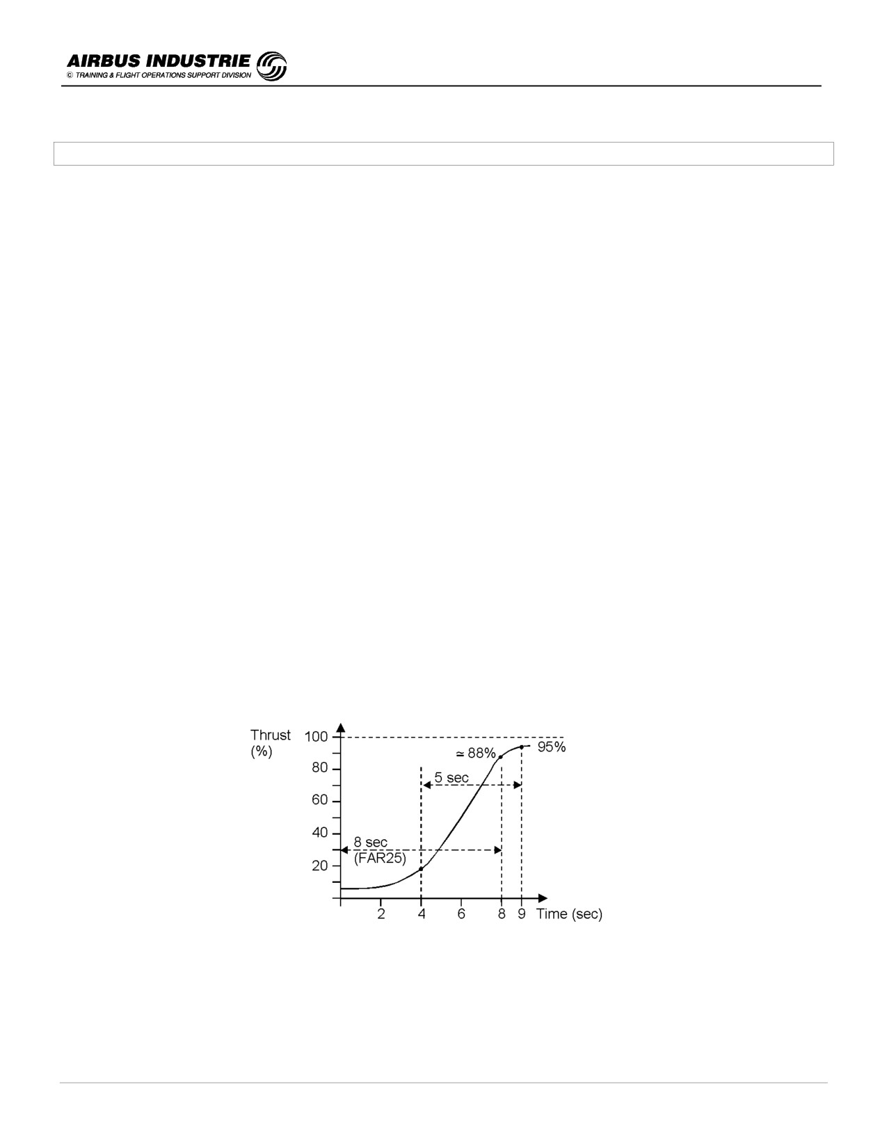
When the pilot sets TOGA thrust for Go Around, it takes some time for the engines to spool up due to the
acceleration capability of the high by pass ratio engines.
The engine certification criteria ensures a Maximum time to accelerate from 15% to 95% of the Go Around
thrust in 5 sec. (FAR 23). 15% of TOGA is typically the thrust required to fly VAPP in landing configuration on a
typical - 3° descent path.
The airframe certification criteria ensures that, within 8 sec., the thrust which can be achieved from approach idle,
allows the aircraft to fly the minimum "Landing climb gradient" 3.2%, with all engine operative in landing
configuration.
DATE: JAN 2001
Page 80
UDY0102
A320 INSTRUCTOR SUPPORT
NORMAL OPERATION
-
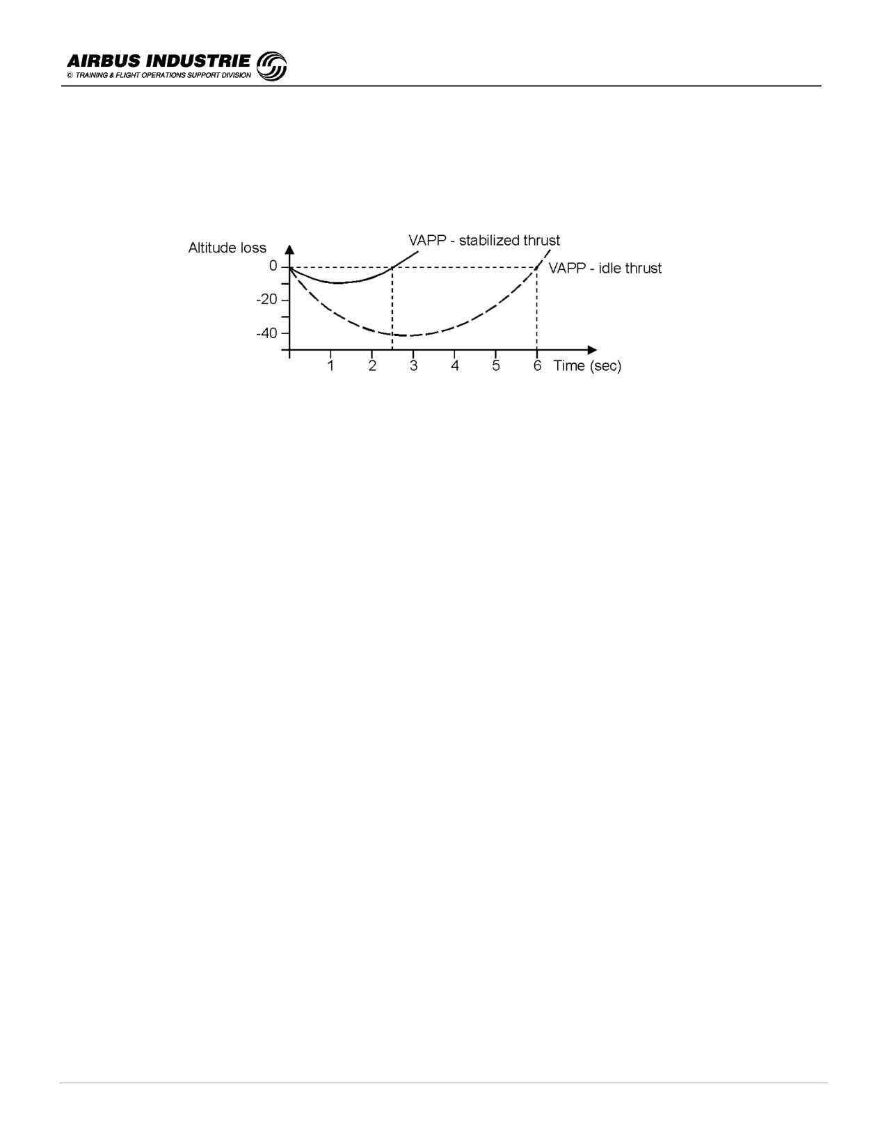
Therefore when the pilot initiates a Go Around while on the final descent path, he must be aware that the aircraft
will initially loose some altitude. This altitude loss will be greater:
• If the initial thrust is close to Idle.
• If the aircraft speed is lower than VAPP (backside of the thrust/speed curve).
During the Go Around phase the target speed is GREEN DOT above GA ACCEL ALT.
How to get out of Go Around phase ?
The purpose of getting out of the Go Around phase is to obtain the proper target speed, and proper predictions
depending upon the continuation of the flight as decided by the pilot.
During the missed approach the crew will elect a strategy which it will indicate to the FMS (indeed the FMS is unable to
choose a strategy!…):
-
either come back and land ➜ ACTIVATE APPR PHASE,
-
or divert to an ALTN airfield. There are 3 possibilities to indicate this to the FMS:
• the ALTN FPLN has been prepared
⇒ Lat Rev at TO WPT + ENABLE ALTN,
• the SEC FPLN has been prepared to a diversion airfield
⇒ ACTIVATE SEC FPLN (HDG mode must normally be active).
• Nothing has been prepared! Then select SPD 250 kt + OP CLB to initiate climb. Insert NEW DEST + CRZ FL;
then finalize the diversion FPLN.
The Go Around phase will automatically switch to CLB phase (or to appropriate phase - depending on altitude), and
managed speed target is then initial climb speed.
Once the aircraft has started the final approach, a Go Around or missed approach must be considered:
-
If there is a loss or a doubt about situation awareness.
-
If there is a malfunction which jeopardizes the safe completion of the approach.
-
If the ATC changes the final approach clearance resulting in rushed reaction from the crew or potentially unstable
approach.
-
If the approach is unstable in speed, altitude, flight path (vertical or lateral) or configuration, in such a way that
most probably it won't be stable by 1000 ft AGL in IMC, or by 500 ft AGL in VMC.
-
If adequate visual cues are not obtained at MDA or DH.
-
If any GPWS/TCAS or Windshear alert occurs.
DATE: JAN 2001
Page 81
UDY0102

A320 INSTRUCTOR SUPPORT
NORMAL OPERATION
16 - ETOPS
!
Background
ETOPS stands for Extended range Twin engine aircraft OPerationS.
ETOPS describes the operations of Twin Engine A/C over routes that contain waypoints located further than one hour
flying time from an adequate airport at one engine inoperative cruise speed.
The ETOPS regulations are applicable to overwater or overland operations and to all revenue flights with passengers
or freighters.
The purpose of ETOPS regulations is to provide a greater flexibility in twin engine aircraft operation while maintaining
a high level of safety.
In the 80’s ICAO formed an ETOPS study group to examine the flexibility of extended range operation, while the FAA
begun the design of AC 120-42 which defines the US criteria for ETOPS.
During the 80’s and 90’s the various aspects of ETOPS criteria have been thoroughly reviewed by the industry allowing
now to consider over 180 mn ETOPS (up to 207 mn is proposed by the US to day, for obvious reasons...!).
!
Regulatory Aspects of ETOPS
The purpose of the regulations is to ensure that twin engine A/C operating under ETOPS are at least as reliable as the
existing 3 or 4 engine A/C.
The regulations cover 2 aspects:
a)
The A/C ETOPS type design approval.
The A/C manufacturer has to demonstrate that the A/C complies with the ETOPS design criteria. Any changes required
to the A/C basic design are contained in the “Configuration, Maintenance and Procedure Standards” (CMP) which is an
authority approved document.
Design considerations cover the following issues:
→ Propulsion System Reliability,
→ Electric power redundancy and distribution consideration,
→ APU design,
→ Single Engine operation with adequate system redundancy,
→ Ice protection for engine and air frame,
→ all system safety assessment to take into account the max diversion time,
→ adequate fire extinguishing system for cargo and
→ crew workload consideration under failure conditions.
The ETOPS capability assessment is done by the Airworthiness Authorities who analyze the IFSD rates (In Flight Shut
Down) and all in-service events in order to grant the Maximum allowed ETOPS diversion time for the candidate A/C.
The A320 family is granted 120 mn with all installed engines. A319CJ is planed to be granted 180 mn in 2001. Up to
now, no airline has officially requested for the A320 family an extension of the diversion time up to 180 mn.
DATE: JAN 2001
Page 82
UDY0102
A320 INSTRUCTOR SUPPORT
NORMAL OPERATION
b) The ETOPS operational approval given to the airlines.
The airline has to demonstrate its competence to the authorities regarding flight operations, flight procedures, A/C
configuration, maintenance, dispatch practices and ETOPS training.
Each authority defines its own means of compliance stating the method the airline has to use to demonstrate its
competence.
In order to get 120 mn diversion time approval, the regulations require from the candidate airline to accumulate 12
months of consecutive in service experience on the A/C and engine type. But an “accelerated ETOPS approval
scheme“ may be applied by the airline.
!
ETOPS Flight Dispatch
The ETOPS flight preparation process determines the specific documentation and data, which will be handed over to
the crews at flight dispatch.
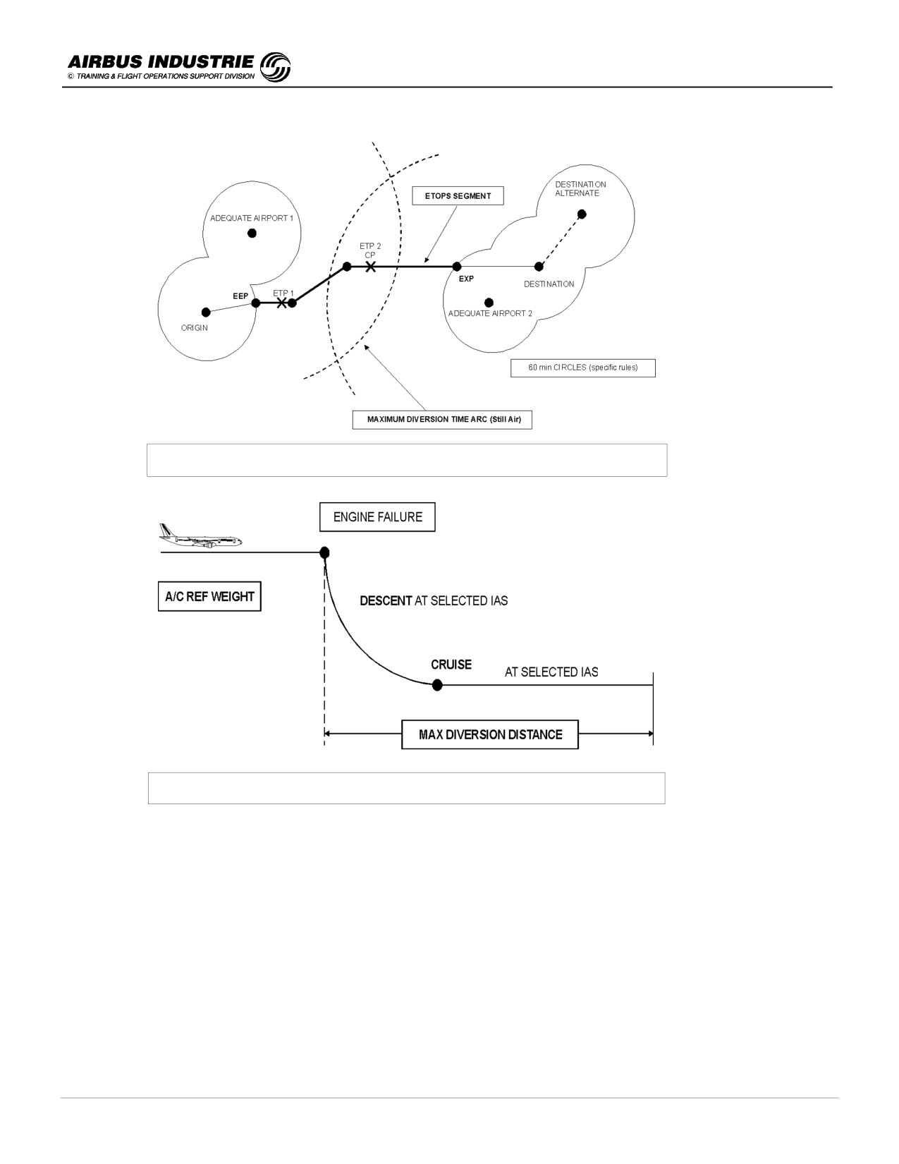
a) Definitions
-
ETOPS operation
Flight conducted on a twin engine A/C over a route containing a point further than 60 mn flying time from an
ADEQUATE airport.
The “Maximum Diversion Distance” with 60 mn diversion time is determined in STILL AIR and ISA conditions
according to specific rules.
)
See diversion speed schedule.
-
Adequate Airport
Airport acknowledged by the AA, which satisfies A/C performance requirements at expected LW. The airport
must be available at the expected time of use, capable of ground operational assistance, equipped with at least
one approach navaid, fire fighting and rescue facilities.
-
Suitable Airport
Adequate airport which satisfies ETOPS dispatch weather requirements within a validity period (one hour
before earliest ETA, to one hour after the latest ETA). Wind limitations at landing are to be considered.
-
Maximum Diversion Time
Granted by the AA - From 75 mn to 180 mn from a diversion airport; it is used to determine the ETOPS area of
operation for dispatch purposes.
-
Maximum Diversion Distance
Distance covered in Still Air/ISA or ∆ ISA conditions within the maximum diversion time at the SELECTED
ONE ENGINE OUT SPEED and ASSOCIATED ALTITUDE.
The EEP (ETOPS ENTRY POINT) is located at 60 mn flying time from the last ADEQUATE AIRPORT. The EXP
(ETOPS EXIT POINT) 60 mn from the first ADEQUATE AIRPORT.
The ETPs (Equitime Point) and CP (critical point) are determined from SUITABLE AIRPORTS with FORECASTED
ATMOSPHERIC CONDITIONS.
DATE: JAN 2001
Page 83
UDY0102
A320 INSTRUCTOR SUPPORT
NORMAL OPERATION
b)
ETOPS AREA OF OPERATIONS - DIVERSION STRATEGIES.
The ETOPS area of operation is the area in which it is permitted to conduct a flight under ETOPS - it is a function of
-
Adequate Airports,
-
Max Diversion Time granted by AA and
-
EO Speed Schedule.
This area of operations is determined once, in Still Air conditions and ISA. It does not need to be reassessed.
The Airline chooses the DIVERSION STRATEGY to be applied in order to determine the ETOPS area of operation.
The Diversion strategy defines, amongst others, the Engine Out Speed schedule which will condition the Diversion
Distance; thus the diversion strategy will be determined so as to ensure a minimum overlap of the diversion distance
circles, a proper obstacle clearance if any, and a safe fuel policy.
There are 3 possible Diversion Strategies:
-
STANDARD - CRZ MACH 0.78 M/300 kt descent down to LRC CRZ FL,
-
OBSTACLE - DRIFTDOWN GREEN DOT/MCT descent; when obstacles are cleared, then cruise at LRC CRZ FL
and
-
ETOPS FIXED SPEED STRATEGY - Several speed samples are defined for each aircraft type. This is the
“minimum time strategy“, which however must allow the net flight path to clear the obstacles.
For the A320 the typical speed scenarios are 0.80 M/350 kt at MCT or 0.78 M/320 kt at MCT.
Thus the operator determines a reference GW and selects a diversion strategy. It allows him to draw the maximum
diversion distance circles around the adequate airport and thus to determine the ETOPS area of operation.
FCOM 2.04.40 provides the 60 mn maximum diversion distance at FL170 (as per JAR OPS 1-245) used to decide if a
route is ETOPS. This distance is used to draw the 60 mn distance circles and to locate the EEPs and EXPs.
e.g A319-113/114 (CFM56-5A1/A3)
TOW = 75500 kg
D = 386 NM
A319-132 (IAE V2524-A5)
TOW = 75500 kg
D = 405 NM
A319CJ-115 (CFM56-5B7)
TOW = 75500 kg
D = 407 NM
A319CJ-133 (IAE V2527M-A5)
TOW = 75500 kg
D = 407 NM
A320-214 (CFM56-5B4 SAC)
TOW = 77000 kg
D = 403 NM
A320-232 (IAE V2527-A5)
TOW = 77000 kg
D = 402 NM
A321-111/112 (CFM56-5B1/B2 SAC)
TOW = 80000 kg
D = 401 NM
A321-131 (IAE V2530-A5)
TOW = 80000 kg
D = 395 NM
A321-211 (CFM56-5B3)
TOW = 89000 kg
D = 385 NM
A321-231 (IAE V2533-A5)
TOW = 89000 kg
D = 373 NM
FCOM 2.04.40 provides the diversion distances for various speed schedules and GW, used to draw the maximum
diversion time circles or arcs and thus to determine the area of operations.
DATE: JAN 2001
Page 84
UDY0102
A320 INSTRUCTOR SUPPORT
NORMAL OPERATION
60 mn Diversion Circles and Maximum Diversion ARCS
Determination of the Maximum Diversion Distance
c)
Determination of SUITABLE Airports.
An adequate airport is SUITABLE when the weather forecasted at this airport is better in terms of ceiling and visibility
than the REQUIRED MINIMA FOR DISPATCH during the EN ROUTE ALTN SUITABILITY PERIOD. Landing wind
limitations are to be considered as well.
-
The required minimum at en route alternate for dispatch for ETOPS are HIGHER than the normal defined minima
at the airport. They are determined by the FAA or JAA regulations; they are published in FCOM 2.04.40.
e.g: ONE RUNWAY with one instrument approach ILS or NPA (+ Circling or not):
> minimum alternate airfield ceiling = [DH or MDH] + 400 ft or Circling minima,
> minimum alternate airfield visibility = authorized visibility + 1500m (JAA rule).
DATE: JAN 2001
Page 85
UDY0102
A320 INSTRUCTOR SUPPORT
NORMAL OPERATION
The surface conditions (forecast crosswind component, including gust) must not exceed the maximum permitted
crosswind for landing; fluid contaminated runway is to be considered (2.04.10).
e.g.:
for the A320 family (3.01.20):
-
max crosswind for LDG demonstrated 33 kts gusting 38kts and
-
max tailwind for LDG 10 kts.
Be aware that:
-
Runway course is MAGNETIC (except at very high latitudes),
-
METAR & TAF give TRUE wind,
-
VOLMET gives TRUE wind and
-
ATIS & TWR give MAGNETIC wind.
e.g.: SONDERSTROM
-
RUNWAY 10 is 100° magnetic. Variation 40° W,
-
METAR WIND 125°/ 35 kt is TRUE (= WIND 165°/ 35 kt is MAGNETIC),
+
CROSSWIND = 32 kt.
The EN ROUTE ALTN SUITABILITY period is determined as being between
-
ONE HOUR BEFORE THE EARLIEST TIME OF ARRIVAL and
-
ONE HOUR AFTER THE LATEST TIME OF ARRIVAL.
This suitability period is provided for the ESTIMATED TIME OF DEPARTURE. It must be UPDATED with the ACTUAL
DEPARTURE TIME.
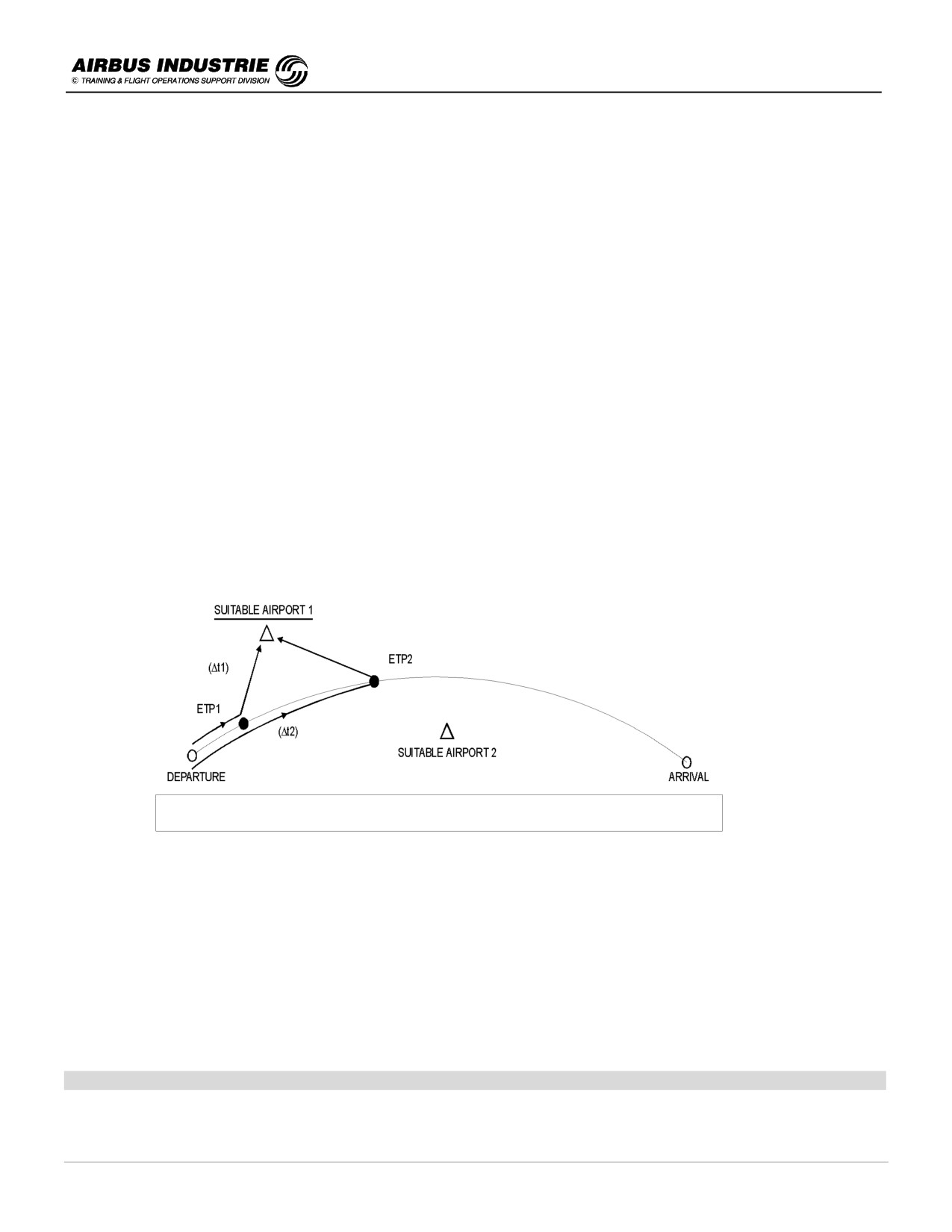
En Route ALTN Suitability Period
Let us consider the example here above:
ETP1 - equitime point between departure and suitable airport 1,
ETP2 - equitime point between suitable airport 1 and 2,
ETPs are determined FOR THE ENG FAIL CASE (EO cruise altitude, wind, time).
NOTE:
The ETPs determined in the FMS are computed with two engine operative.
∆t 1 from departure to suitable 1 is determined at NORMAL CRUISE SPEED / FL, via ETP1.
∆t 2 idem to suitable 2 via ETP2.
PERIOD = (ETD + ∆t1 - 1h); (ETD + ∆t2 + 1h).
[EN ROUTE ALTN SUITABILITY PERIOD = (ETD + ∆t1 - 1h); (ETD + ∆t1 + 1h)]
DATE: JAN 2001
Page 86
UDY0102
A320 INSTRUCTOR SUPPORT
NORMAL OPERATION
d)
Fuel Requirements
The dispatcher determines the fuel required for a given route considering
-
STANDARD FUEL PLANNING and
-
SPECIFIC ETOPS FUEL REQUIREMENTS.
The STANDARD FUEL PLANNING is:
-
TAXI + TRIP + RSV + ALTN + 30 mn HOLD at ALTN.
The SPECIFIC ETOPS REQUIREMENTS consist in determining the fuel, which would be required to reach a suitable
airport in case of
-
an Engine out situation,
-
a failure of the pressurization system and
-
an engine failure linked to a pressurization failure.
This fuel is computed from each ETP to the associated suitable diversion airport, for each failure case.
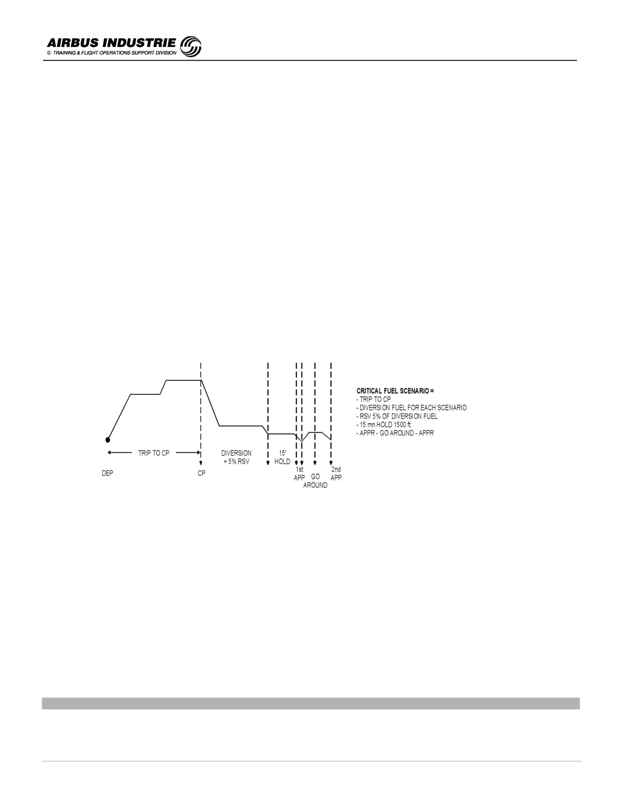
The ETP on the route which is CRITICAL REGARDING THE ETOPS FUEL REQUIREMENTS is called CRITICAL
POINT (CP). It is usually the LAST ETP of the ETOPS SEGMENT.
The dimensioning FAILURE SCENARIOS are:
-
FAILURE OF PRESSURIZATION and
-
FAILURE OF PRESSURIZATION + EO, for the A320.
NOTE:
A contingency around 2% to 3% is recommended on the trip to CP although not required by regulations.
Considerations for ETOPS Fuel:
-
Diversion fuel tables from CP to LDG including holding/2 approaches/Go Around for the 2 dimensioning failure
scenarios are provided in FCOM 2.04.20.
-
Additional fuel is to be considered for ICING conditions:
> for EAI / WAI use and
> for potential ice accretion on unheated surfaces.
Additional fuel due to the potential drag of ice accretion on unheated surfaces is a %tage of the fuel burnt during the
considered exposure time. The value of this %tage is equal to 5 times the forecast exposure time in hours (1 hour +
5%, 2 hours +
10%).
If moderate icing is forecast, the above fuel provision is divided by 2 (see FCOM 2.04.40 - ETOPS CRITICAL FUEL
RESERVE).
Some airlines add a contingency on the trip from departure to CP (as recommended hereabove).
FUEL RQD FOR ETOPS SECTOR = MAX {STD FUEL, SPECIFIC ETOPS FUEL REQUIREMENT}
DATE: JAN 2001
Page 87
UDY0102
A320 INSTRUCTOR SUPPORT
NORMAL OPERATION
e) Crew Duties at Flight Dispatch.
The following mnemonic can help. It is MNPS (which has nothing to do with the North Atlantic operation or Minimum
Navigation Performance!).
Meteo:
TAF/METAR/SIGMET at departure/arrival/en route alternate.
Consider SUITABILITY PERIOD
TEMSI-ICING FORECAST
WIND/TEMP at CRZ FL and DIV FL
Notam and Navigation:
Check departure/arrival/en route alternate Notams.
) CONFIRM SUITABLE AIRPORTS.
ETOPS Area chart - Check ETOPS Area (EEP-EXP) - Identify ETPs.
Performance:
Perf. factor / CI / Icing constraints / MEL - CDL constraints.
Review CFP
-
versus ATC F.PLN,
-
check Trip Fuel (2.05.40),
-
check Critical Fuel Scenario (2.0540); whether additional ETOPS fuel required or not.
Determine FUEL RQD and Expected TOW → T/O data.
Determine WINDs to be inserted for the FMS - en route and overhead suitable Airports for ETPs.
Status:
Aircraft for ETOPS dispatch,
Crew (qualified …).
The Route itself.
NOTE:
Be aware that the time estimates from an ETP to two associated suitable airports are usually different on the CFP.
This is normal because ETPs are determined for the engine failure case, which means at EO cruising altitude with
associated winds and at the selected EO IAS.
The predictions on the CFP from ETP assume the CRITICAL FUEL SCENARIO which is in most cases the failure of
pressurization or the combination of Engine failure and Failure of pressurization.
If the critical case is the pressurization failure, for example, the estimates will assume the aircraft will fly at FL100, with
associated winds at that FL and with LRC speeds at FL100.
→ The estimated times at suitable airports will be different.
→ The time between ETP at a suitable airport may be greater than the "approved diversion time" (120 mn or 180 mn)
which are used to determine the "ETOPS area of operation"; but those times are used to determine the so called
Maximum Diversion Distance in still air, at the selected one engine out speed.
!
ETOPS In Flight Operation.
The crew must be AWARE OF THE DISPATCH CONSTRAINTS (weather minima, fuel); but must be aware that
NORMAL CONDITIONS APPLY ONCE IN FLIGHT in terms of weather minima, fuel estimates at CP. Furthermore in
case of emergency (depressurization, EO) the Captain will elect the most suitable speed schedule or strategy, which
might be different from the one of the dispatch, if he judges it to be necessary.
a)
Cockpit Preparation (ETOPS Specifics)
-
Crew ensures that MAINTENANCE PREFLIGHT checks are completed
-
Specific system checks: STAND BY GEN (ASAP so as not to corrupt refuel, cabin etc.) and FUEL X FEED valve.
-
IRS: Perform full alignment.
-
FMS handling as for any Long Range Flight.
Additionally insert EEP/EXP on STORED WPT page (CFP ETPs may also be stored).
b)
After Engine Start
Once the engines are started and BEFORE THE A/C IS MOVING UNDER ITS OWN THRUST, ETOPS MEL
restrictions have to be applied.
Once the A/C is taxiing, the MEL does not apply any longer, unless the airline policy is different or captain’s decision.
DATE: JAN 2001
Page 88
UDY0102
A320 INSTRUCTOR SUPPORT
NORMAL OPERATION
c) In Flight
Before reaching EEP
-
Insert wind/temp into FMS for proper predictions.
-
Copy Active into SEC FPLN and prepare first applicable diversion FPLN.
-
Check weather at en route ALTN by listening to VOLMET or by contacting Airline Flight watch via ACARS, HF
STOCKOLM… or any other means. Weather at suitable airports must be BETTER THAN STANDARD
PUBLISHED MINIMA (or than authorized minima if higher).
-
A/C Status must be ok for ETOPS.
+ If WEATHER or A/C STATUS become NOT SATISFACTORY, the crew must contact the ETOPS FLT WATCH
OFFICE for a possible REROUTING, which must be available before EEP.
Once in ETOPS Area
-
There is no longer a requirement for weather to remain BETTER THAN STD MINIMA.
-
Always check weather at DEST and ALTN.
-
Update the ETPs along with flight progress.
Fuel Monitoring
-
Normal or STD fuel policy applies.
-
Amongst others, the FUEL at CP must be above the minimum required to continue the flight to destination or to en
route alternate in normal conditions; the amount of fuel must allow the aircraft to land at least at destination or
divert and land, with at least the FINAL reserve (30 mn hold at 1500 ft).
The CP shall not be considered as a reclearance point.
Navigation
-
Standard navigation procedures apply. With GPS PRIMARY, no specific precautions.
-
In case of loss of GPS PRIMARY:
> use any VOR/DME or BEACON to consolidate FMS position,
> determine the BEST IRS on DATA POS MON,
> in case of loss of one IRS, use AP on side of the BEST IRS and
> consult the CLOSEST ARPT and update ETPs as required.
d)
Diversion
There are specific reasons to divert in case of ETOPS:
-
weather at suitable airport getting below minima BEFORE EEP,
-
failure requiring LAND ASAP,
-
failure leading to excess FUEL CONSUMPTION (depressurization, fuel trapped in CTR TK, …) and
-
Cargo Fire (divert at maximum speed).
DATE: JAN 2001
Page 89
UDY0102

A320 INSTRUCTOR SUPPORT
NORMAL OPERATION
17 - RVSM
A few words about Reduced Vertical Separation Minimum airspace where the aircraft flying between FL 290
and FL 410 are separated vertically by 1000 ft instead of 2000 ft.
The purpose of RVSM is to allow to increase the traffic rates in saturated airspaces, while keeping up the same safety
level. Since vertical separation is planned to be reduced, this necessitates some requirements on aircraft equipment,
on flight crew training, on ATC personnel training, on aircraft maintenance and MEL, and on altitude performance
monitoring.
The RVSM has been first implemented in the NAT MNPS area initially between FL330 to FL370, then in the full altitude
intended range. This first operation has allowed to detect the existence of spurious Traffic advisories (this has dictated
the TCAS II change 7, amongst others), as well as some wake vortex encounters (this has dictated some specific
lateral
offset
procedures
in
case some special weather
conditions
are
encountered).
Then RVSM has been applied over Pacific, and will be applied over Europe.
As for any special operation of this type (ETOPS, RVSM, MNPS…) following considerations apply:
1. The A/C must be certified for RVSM:
- Minimum altimetry performance must be demonstrated (e.g. the mean Altimetry System Error must be within
80 ft).
- The A/C must carry a minimum set of equipment which in turn dictates the MMEL dispatch conditions which are:
-
2 ADR or 2 ADCs.
-
1 ATC transponder.
-
1 FCU for altitude selection and climb/descent AP mode selection (2 FCU channels minimum).
-
1 Autopilot.
-
1 FWC for altitude alert.
-
2 PFDs and DMCs for altitude display.
- A comparative check of altitude readings in flight at 3 different flight levels from all altimetry sources must fall
within tolerances (in FCOM 3-04-34 see below), and must be recorded.
2. The airline must be approved for RVSM operation by local Authorities, which necessitates that all operation
documentation has been amended, that flight crews are trained, that the maintenance program is reviewed and that
the airline participates to an "altitude keeping performance" monitoring program.
3. Specific procedures have to be applied,
- by the maintenance team, on the equipment required for RVSM,
- by the crews in flight.
The outstanding in flight procedures are:
• Cockpit preparation:
-
Maintenance log / form properly documented.
-
RVSM MEL dispatch conditions are fullfilled.
-
RVSM tolerances properly fulfilled on each PFD (on side ADR versus ADR3; ∆ ALT < 25 ft).
-
Review weather forecast with particular attention to severe turbulence.
-
Check letter W in field 10 of ATC Flight Plan.
• Before reaching RVSM airspace:
-
Any failure of the required equipment leads to rerouting away from RVSM airspace.
-
Two main altimeters indications on STD setting must be within 200 ft.
-
If one ADR fails, check the remaining ADRs versus the STD BY ALTI and note the δ. This will be useful in case of
a subsequent failure.
DATE: JAN 2001
Page 90
UDY0102
A320 INSTRUCTOR SUPPORT
NORMAL OPERATION
• Within RVSM
-
Use AP for cruise Flight and level change (OVERSHOOT < 150 ft).
-
Periodically check ADR tolerances (∆ ALT < 200 ft); use AP and ATC on side ADR in agreement.
NOTE:
The TCAS (unless change 7) may output some spurious TAs (and exceptionally RAs) when crossing or overtaking a
traffic.
• Problems within RVSM
The nature of the problem is linked to the ability to properly maintain a Flight Level:
-
Loss of altimeter redundancy (only one PFD indication)
-
Loss of two APs
-
Failure of a system affecting the aircraft's ability to maintain the flight level
-
Severe turbulences …
→ NOTIFY ATC; "Unable RVSM due to equipment or turbulences…" and apply the contingency procedure as
assigned by ATC.
→ Report the failure in the maintenance log.
Altitude Tolerances for RVSM operation
ADR1 / ADR2
ADR1 (ADR2)
STD BY ALT1/
IAS
on PFD
ADR3 on PFD
ADR1 - ADR2 - ADR3
[kt]
[ft]
[ft]
[ft]
GROUND
-
20
20
-
FL50
250
50
80
130
FL100
250
55
80
185
FL200
300
90
145
295
FL300
.78 M
130
355
390
FL410
.78 M
130
365
445
NOTE:
The Airline must report within 72 h to the responsible authority height keeping deviations if those exceed:
-
Over 300 ft (total vertical error as measured during altimeter monitoring program)
-
An altimeter system error over 245 ft.
-
A cleared altitude deviation over 300 ft.
DATE: JAN 2001
Page 91
UDY0102
A320 INSTRUCTOR SUPPORT
NORMAL OPERATION
18 - PERFORMANCE CONSIDERATIONS
I - General
The wing of the A320 has been designed to be best efficient at “around” a cruise Mach Number of 0.78 (which defines
its sweep angle and thickness).
However the cost of a given sector depends upon the fuel consumption but also of many other factors such as
→ Over flight charges,
→ Price of fuel at origin, destination leading to possible fuel tankering,
→ Price of flight time (crew, maintenance …),
→ Wind gradient, flight plan constraints (such as constant Mach …) and
→ Aircraft GW itself etc.
For each sector, the airline determines a cost factor:
COST 1 mn FLIGHT
the COST INDEX CI =
COST 1 mn FUEL
where the cost of variable items is considered. The greatest variables are FUEL / MAINTENANCE. However despite
the fact that the crew costs are fixed, duty time constraints leading to a night stop will modify the costs index of a given
sector.
Once a COST INDEX is determined for a given sector, this allows the FMS to generate a CLIMB / CRUISE /
DESCENT SPEED profile which will minimize the cost, by balancing the cost of fuel against the cost of time.
For example, if the fuel consumption is the essential economical factor on a given sector, the COST INDEX will be
LOW (0 is MAX RANGE), the time is the essential economical factor on a given sector, the COST INDEX will be HIGH
(999 is MIN TIME).
It is essential to understand that once the CI is defined for a given sector, the MANAGED SPEED PROFILE will be
computed by the FMS, as well as the OPTIMUM FLIGHT LEVEL, OPTIMUM STEP etc.
Furthermore with Cruise Wind variations and temperature changes, the Cruise Mach number will vary, as it varies also
with GW and cruise altitude.
For example at GW 65 t FL350 on an A320-212 / CFM56-5A3
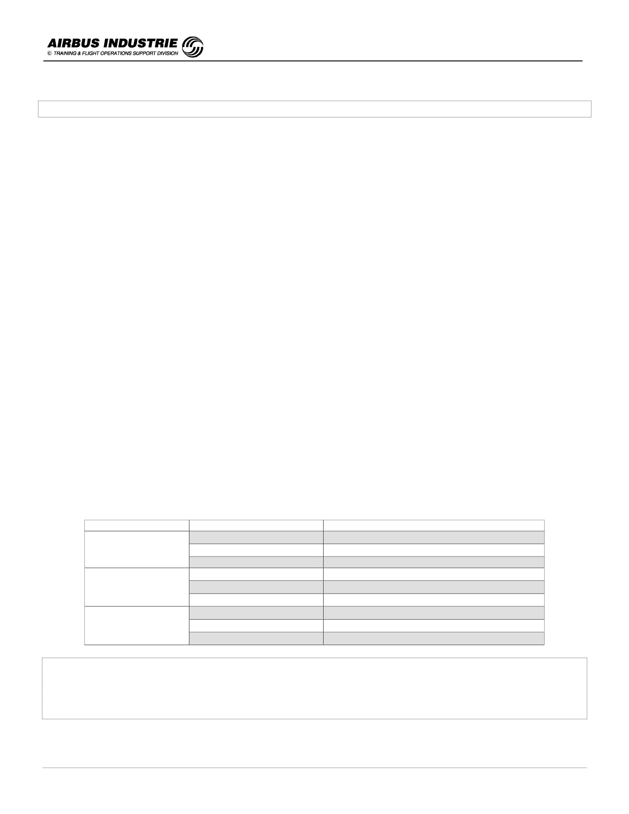
CI
WIND COMPONENT
ECON CRZ MACH [M]
Head Wind 100 kt
0.782
0
Still Air
0.781
Tail Wind 100 kt
0.769
Head Wind 100 kt
0.790
50
Still air
0.796
Tail Wind 100 kt
0.802
Head Wind 100 kt
0.811
100
Still Air
0.804
Tail Wind 100 kt
0.803
As a consequence, the COST INDEX IS NOT TO BE MODIFIED BY THE CREW IN FLIGHT, unless for FUEL or
FLIGHT TIME CONSIDERATIONS.
If for any reason, the crew wishes to fly at a GIVEN FIXED CRUISE MACH NUMBER, SELECT IT ON THE FCU (all
predictions will be updated accordingly).
DATE: JAN 2001
Page 92
UDY0102
A320 INSTRUCTOR SUPPORT
NORMAL OPERATION
II - Take off Considerations
Unreliable Speed Indication
Before ACCEL ALT
) TOGA / PITCH 13°
Crossing ACCEL ALT
) CLB / PITCH 10°
+ 15 sec FLAP1
+ 15 sec FLAP0
Performance Data
T/O Segment Reminder
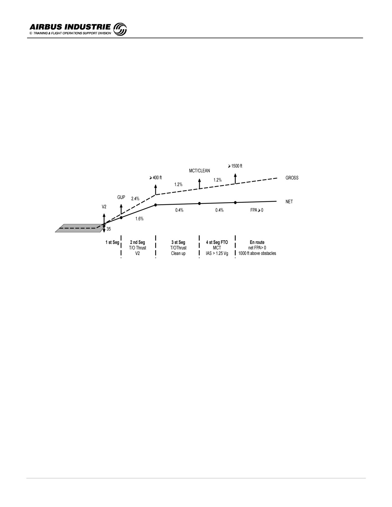
The ENGINE OUT ACCELERATION ALTITUDE must be
-
at least HIGHER than the MINIMUM ALTITUDE required for OBSTACLE CLEARANCE,
but limited to the ALTITUDE reached at the END of CLEAN UP with 10 mn TOGA THRUST
Definition of speeds associated to Take-off
VMCG:
mini control speed on the ground, using PRIMARY CONTROLS only (no NWS). Maximum rudder
force 68 kg / Maximum lateral deviation on ground 30 ft.
VEF:
engine failure speed allowing the crew to recognize the failure and act when reaching V1. There is
typically 1 sec between VEF and V1 (which leads to approx 4 kts).
On a twin engine, if the Take-off is CONTINUED following an engine failure BEFORE VEF, this leads
to a significant increase in Take off Dist (TOD). E.g if the failure occurs 8 sec below VEF, V2 will be
reached at 10 ft instead of 35 ft at the end of TOD.
VMBE:
maximum braking energy speed, at which the brakes can absorb all the energy required.
VMBE becomes a limiting factor at high OAT on long runways. An RTO achieved in such
circumstances may lead to very hot brakes, tires automatically deflated and potential fire.
V1:
Commital speed for Take off. V1 call out must be made so that “ONE” is called when V1 is reached.
VMU:
minimum unstick speed is the speed at which the aircraft can safely lift off the ground and continue
take off. VMU is a function of GW, Aircraft configuration and altitude.
VR:
rotation speed. Allows the aircraft to reach V2 at 35 ft with engine failed. A rotation initiated before VR
leads to a potential tailstrike.
The HIGHER THE FLAP SETTING, the GREATER THE TAIL CLEARANCE is.
V2:
minimum speed reached at 35 ft with one engine failed. It must be between 1.13 Vs1g and 1.28 Vs1g.
The HIGHEST V2 is, the BETTER IS THE A/C CLIMB OUT GRADIENT IN T/O SEGMENTS.
DATE: JAN 2001
Page 93
UDY0102
A320 INSTRUCTOR SUPPORT
NORMAL OPERATION
VMCA:
minimum control speed with one engine out using maximum rudder deflection and 5° bank angle
towards engine inoperative.
Flying BELOW VMCA leads to a significant INCREASE of the SLIDE SLIP (Beta Target); thus, if in
case of an engine failure the PILOT
IS
UNABLE TO CENTER BETA with FULL RUDDER →
ACCELERATE.
Relations between all those speeds:
VMCG
≤ VEF ≤ V1 ≤ VMBE
VR
≥ 1.05 VMCA
VLOF
≤ V MAX TIRE
V2
≥ 1.1 VMCA
On SA family, Vmax tire = 195 kt
A/C
VERSION
ENGINE
VMCG
VMCA [kt] (Alt = 0 ft)
VMBE
A319
A319-111
CFM 56-5-B5
105.5
108
170.6
A319-112
CFM 56-5-B6
108
111
164.2
A319-113
CFM 56-5-A4
104
108
166.9
A319-114
CFM 56-5-A5
107.5
111
171.4
A319-115
CFM 56-5-B7
113.5
114.5
169
A319-131
IAE V2522
104.5
107
173.1
A319-132
IAE V2524
107.5
109.5
172.2
A319-133
IAE V2527M
111.5
133
171.9
A320
A320-111
CFM 56-5-A1 *
107
105
174.2
A320-211
CFM 56-5-A1 *
107
105
160.2
A320-212
CFM 56-5-A3
110.5
110.5
156
A320-214
CFM 56-5-B4
111.5
110
155.1
A320-231
IAE V2500
101.5
108.5
160.7
A320-232
IAE V2527
112.5
111.5
158.7
A320-233
IAE V2527E
112.5
111.5
158.4
A321
A321-111
CFM 56-5-B1
104.5
109
171.9
A321-112
CFM 56-5-B2
106
110.5
171.4
A321-211
CFM 56-5-B3
106
114
173.4
A321-131
IAE V2530
109
112.5
167.9
A321-231
IAE V2533
109
114
170.1
* A320 - 111 MTOW 68 T; A320 - 211 MTOW 77 T
NOTE:
VMBE provided here is with no wind, no runway slope, ISA and CONF2.
VMCG and VMCA are function of altitude.
The certification of the A320 has matched the Amendment 42 of JAR / FAR which has considerably increased the
safety margins in case of an engine failure.
For A 319 & A 321, a so called “post amendment 42” applies which states that a 2 sec delay (at constant V1 speed) is
to be applied between the stop decision and the first pilot reaction in order to determine the acceleration/stop distance.
DATE: JAN 2001
Page 94
UDY0102

A320 INSTRUCTOR SUPPORT
NORMAL OPERATION
Influence factors for Take off performance:
There are obviously many factors influencing the take off performance such as aircraft GW, aircraft configuration,
outside conditions (OAT, wind, pressure), the runway available and the obstacles.
Those factors allow the basic T/O DATA to be determined, which have still to be modulated by other influence factors
which must be applied on tactical basis:
-
Runway is WET: this affects the acceleration/stop capability of the aircraft (as well as possibly, its lateral
controllability in case of crosswind). Thus once MTOW and associated T/O speeds, or FLX TEMP and associated
speeds
are
determined
on
a DRY runway
(this
is
the
basic
T/O
data),
- a weight decrement and associated speed decrease must be applied
- or a ∆TFLEX decrement and associated speed decrease must be applied.
-
AIR COND ON: the basic T/O data is often provided on the RTOW charts supposing AIR COND OFF. In that case
if PACKS are ON engine bleeds
-
a weight decrement and associated speed decrease must be applied for MTOW
-
or a ∆TFLEX decrement must be applied; NO speed decrease is to be applied, since the ∆TFLEX decrement
compensates for the thrust drop caused by the AIR COND.
-
QNH different from standard: in case of low pressure, the engine thrust is lower than in STD conditions. Thus in
case QNH << STD
-
a weight decrement and associated speed decrease must be applied for MTOW
-
or a ∆TFLEX decrement must be applied to compensate this thrust drop.
-
ANTI ICE: the same method applies. The decrements are often not provided on the RTOW charts but as defaulted
values in a FCOM specific table.
FLEXIBLE TEMP for T/O reduced thrust - RTOW chart use.
Whenever maximum T/O thrust is not necessary due to aircraft GW or/and runway conditions, it is most efficient to
REDUCE the T/O THRUST in order to SAVE ENGINE LIFE. By limiting the thrust, the centrifrugal forces are reduced
on engine components (blade tip less contact with compressor case). The deposit of molten metal is reduced further
back in the engine (which affects the aerodynamic and thermodynamic efficiency of the engines), the EGT is reduced
(thermal stresses are reduced on the blades, lowering the bending effects).
All A320 engines are high by-pass Turbo Fan engines FLAT RATED till a given temperature called TREF; this means
that BEYOND TREF the maximum thrust of the engine reduces.
Thus by determining an assumed value of outside air temperature which would allow the engines to provide the thrust
required to take off the aircraft in the current conditions, this allows to THE THRUST TO BE REDUCED. This
temperature value is called FLEX TEMP.
THE HIGHER THE FLX, THE MORE THE THRUST IS REDUCED,
THE LOWER IS THE ENGINE EROSION RATE.
DATE: JAN 2001
Page 95
UDY0102
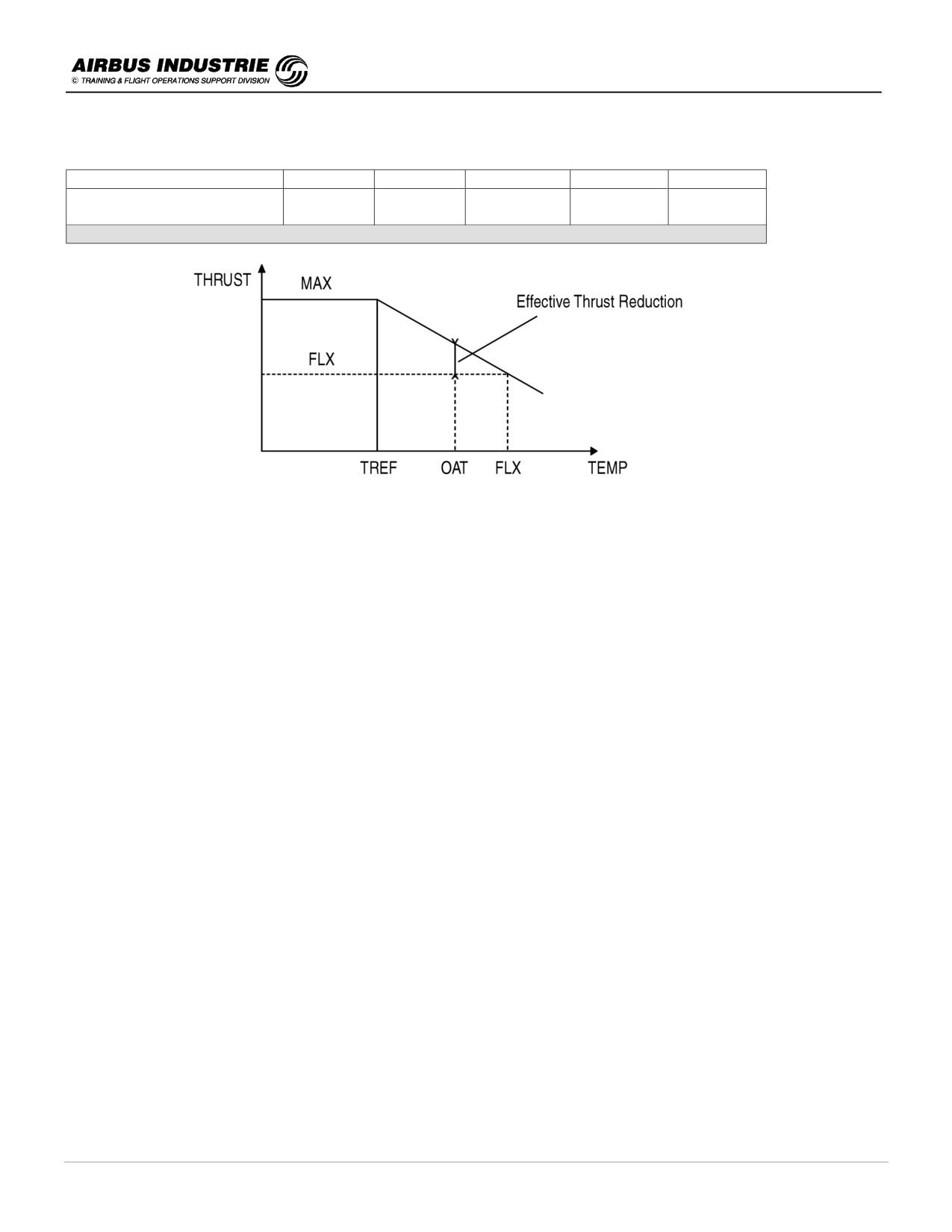
A320 INSTRUCTOR SUPPORT
NORMAL OPERATION
The percentage of the effective Thrust reduction is a function of (FLX TEMP - OAT).
FLX TEMP - OAT [° C]
8°
14°
20°
25°
29°
EFFECTIVE THRUST
5
10
15
20
23
REDUCTION [%]
Indicative figures for A 320-212/ CFM56-5A3
FLX is limited as follows:
-
Max authorized FLX THRUST reduction 25%,
-
FLX T/O N1/EPR ≥ MAX CLB N1/EPR,
-
FLX TEMP by definition > TREF and OAT.
DATE: JAN 2001
Page 96
UDY0102
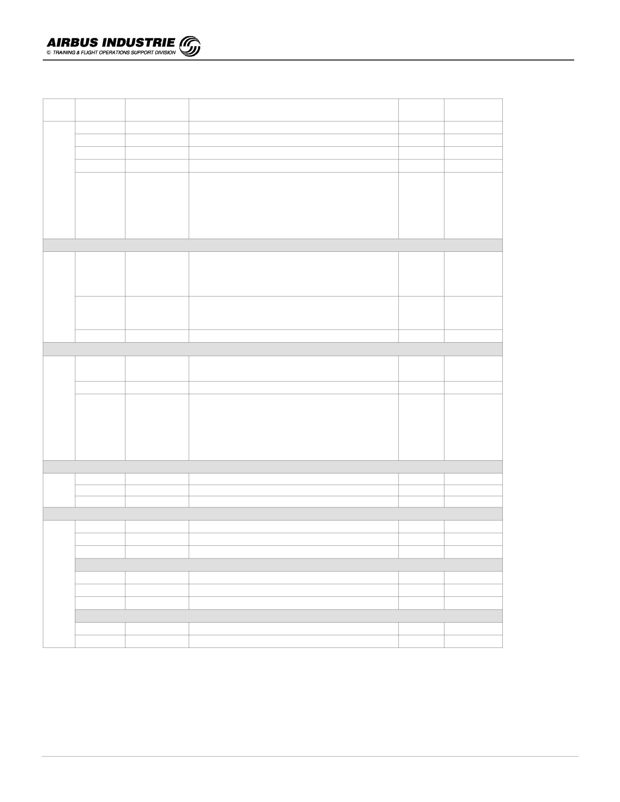
A320 INSTRUCTOR SUPPORT
NORMAL OPERATION
A/C
VERSION
ENGINE
TREF
TMAX
TMAX.FLEX
[°C]
[°C]
[°C]
A319
A319-111
CFM 56-5-B5
ISA + 30
ISA + 40
ISA + 45
A319-112
CFM 56-5-B6
ISA + 30
ISA + 40
ISA + 53
A319-113
CFM 56-5-A4
ISA + 30
ISA + 40
ISA + 44
A319-114
CFM 56-5-A5
ISA + 22
ISA + 40
ISA + 44
A319-115
CFM 56-5-B7
ISA + 29 up to 2000 ft
ISA + 40
ISA + 53
ISA + 18 between 5000 and 10 000 ft
+1 Deg.C per 1000 ft above 10 000 ft up to
ISA + 23 at 15 000 ft
Linear interpolation between
2000 and 5000 ft
A319
A319-131
IAE V2522
ISA + 40 at 8000 ft
ISA + 40
ISA + 65
ISA + 30 at 13 000 ft
Linear interpolation between 8000 ft and
13 000 ft
A319-132
IAE V2524
ISA + 40 at 0 ft
ISA + 40
ISA + 65
ISA + 30 at 5000 ft
Linear interpolation between 0 and 5000 ft
A319-133
IAE V2527M
TREF = f(Zp) TBC or Read it on Takeoff chart
ISA + 40
ISA + 53
A320
A320-111
CFM 56-5-A1
ISA + 15
ISA + 40
ISA + 41
A320-211
A320-212
CFM 56-5-A3
ISA + 15
ISA + 40
ISA + 45
A320-214
CFM 56-5-B4
ISA + 29 up to 2000 ft
ISA + 40
ISA + 53
ISA + 18 between 5000 and 10 000 ft
+1 Deg.C per 1000 ft above 10 000 ft up to
ISA + 23 at 15 000 ft
Linear interpolation between
2000 and 5000 ft
A320
A320-231
IAE V2500
ISA + 15
ISA + 40
ISA + 46
A320-232
IAE V2527
Read it on Takeoff chart
ISA + 40
ISA + 55
A320-233
IAE V2527E
Read it on Takeoff chart
ISA + 40
ISA + 55
A321
A320-231
IAE V2500
ISA + 15
ISA + 40
ISA + 46
A320-232
IAE V2527
Read it on Takeoff chart
ISA + 40
ISA + 55
A320-233
IAE V2527E
Read it on Takeoff chart
ISA + 40
ISA + 55
A321-111
CFM 56-5-B1
ISA + 15
ISA + 40
ISA + 43
A321-112
CFM 56-5-B2
ISA + 15
ISA + 40
ISA + 43
A321-211
CFM 56-5-B3
ISA + 15
ISA + 40
ISA + 43
A321-131
IAE V2530
ISA + 15
ISA + 40
ISA + 45
A321-231
IAE V2533
Read it on Takeoff chart
ISA + 40
ISA + 42
DATE: JAN 2001
Page 97
UDY0102
A320 INSTRUCTOR SUPPORT
NORMAL OPERATION
NOTE:
The use of FLX TEMP adds some “safety” margins for T/O.
Indeed if V1 = 160 kt with FLX 65 → V1 TAS = 172 kt.
If the OAT = 35 °C that day, the effective V1 TAS = 164 kt.
The STOP calculations are computed on V1 TAS 172 kt (as well as would be the GO calculation on the FLX V2 TAS).
This somehow corresponds to a V1 gain of 8 kt, which could equate to 8 (FLX TEMP - OAT) meters gain on distances.
The RTOW charts are not exactly the same for A320 and for A319/A321
(Octopus).
They also may have different presentations according to airline’s choice: entry with GW or with TEMP. For Octopus
charts, the influence factor corrections are provided either in 2 lines or 4 lines.
For A320 charts, the corrections are found in FCOM 2-02-24. In all cases the principle to determine the T/O data is the
same:
1. Determine the MTOW and apply the influence factor corrections.
For Octopus charts, as per the order, those factors are provided on the chart:
-
for the 1st influence, apply the correction from first 2 lines (unless OAT > TVMC in which case the last 2 lines
apply) - NO SPEED CHECK VERSUS V1 / VR / V2 MIN, VMU is necessary,
-
for the 2nd or 3rd influences, apply the corrections as follows:
-
if only 2 lines are provided, achieve a SPEED CHECK,
-
if the SPEED CHECK is NOT SUCCESSFUL, T/O is NOT POSSIBLE UNDER THE PRESENT
CONDITIONS,
-
if 4 lines are provided, USE THE 2 BOTTOM LINES (no speed check required).
2. Determine the FLEX TEMP and apply the influence factor corrections.
For Octopus charts:
-
for the 1st influence correction, apply the FLX and Speed corrections as required, and CHECK SPEEDS
VERSUS V1 / VR / V2 and VMU,
-
for the next one, same method. If 4 line corrections are provided, you may use the BOTTOM 2 LINES with NO
SPEED CHECK; this is very conservative.
If the SPEED CHECK is NOT SUCCESSFUL, FLX is NOT POSSIBLE. Use MAX T/O and the SPEED associated to
MTOW or the SPEEDS ASSOCIATED to CURRENT GW if all those speeds are lower.
NOTE:
For Octopus charts, if GW is lower than any GW provided on the charts, apply all influence corrections first. Then apply
the speed decrement corresponding to lower GW, e.g. 1 kt/t, and check the resulting speed versus V1, VR, V2 min and
VMU.
T/O CONFIGURATION CHOICE
CONF 1 + F / CONF 2 / CONF 3 may be elected for T/O.
A high T/O CONF is preferable to minimize tailstrike risks, or on rough runways to decrease the T/O speeds.
A low T/O CONF (1+F) is preferable to optimize the climb gradient more specifically in hot weather.
As a consequence the general criteria to determine the best T/O CONF are:
-
HIGHEST FLX TEMP (engine life saving),
-
LOWER T/O SPEED and
-
PREFERRED CONF FOR COMFORTABLE A/C HANDLING (e.g. tailstrike).
The preferred T/O CONF is thus CONF2 as long as it does not induce a reduction of FLX TEMP higher than 5°.
CONF 2 provides the best compromise to fulfil these criteria.
Various other factors influencing Take-off
Brakes
The Carbon brakes are quite efficient when hot (≅ 100 °C) or with some wear.
However the Carbon brake temp increases rapidly with brake application.
The HOT BRAKES caution comes up at 300 °C indicating that if the L/G is retracted, there is a potential risk of fire
caused by this temperature being spread to the hydraulic system.
DATE: JAN 2001
Page 98
UDY0102
A320 INSTRUCTOR SUPPORT
NORMAL OPERATION
IF HOT BRAKES BEFORE T/O, DO NOT T/O.
IF HOT BRAKES DURING T/O, DO NOT RETRACT L/G.
DO NOT USE BRAKE FANS DURING T/O, OR IF FIRE.
Tires
Under inflation is one of the major cause of tire failure; it heats up faster and may cause a breakdown of the rubber
material.
The tire develops a BRAKING force when the tire is rolling (not when skidding).
The Brake coefficient is high on a dry runway and LOWER on a WET runway where the brake loss increases with
speed.
Tire wear favors Aquaplaning. With normal tire pressure (around 180 PSI) the aquaplaning speed on STANDING
WATER is around 120 kt, on SLUSH around 130 kt.
A tire failure causes longer T/O distances.
Line Up allowance
Line up allowances after a 90° turn or 180° turn are included in the take off data determination e.g.
ASDA
A 319
A 320
A 321
ASDA line up allowance (90° turn)
23.1 m
25.5 m
28.0 m
ASDA line up allowance (180° turn)
26.4 m
27.5 m
35.8 m
Some Rules of Thumb
Flex Temp [°C]
∆ Thrust [%]
∆ N1 [%]
∆ EGT [°C]
∆ EPR
+ 10
- 6
- 2,9
- 30
- 0,048
Air Cond
∆ Flex Temp [°C]
∆ Thrust [%]
∆ EGT [°C]
Off
+ 3
+ 2,4
- 10
∆ Thrust [%]
∆ N1 [%]
∆ EGT [°C]
∆ EPR
25
- 14
- 251
- 0,128
Runway shortening [m]
∆ TOW [t]
∆ OAT [°C]
- 100
- 1.5
- 5
DATE: JAN 2001
Page 99
UDY0102

A320 INSTRUCTOR SUPPORT
NORMAL OPERATION
III - Climb Considerations
Unreliable Speed Indication
MAX CLB THRUST
PITCH 7°
till FL 100
IAS ≅ 250 kt
PITCH 5°
FL > 100
IAS ≅ 280 kt
PITCH 3°
FL > 200
M 0.76
Performance data
En Route climb gradient (from 1500 ft AGL at origin):
-
Gross climb gradient with one EO
1.1 %
-
Net climb gradient
0
Obstacle clearance criteria:
-
Net flight path must be > 0, 1000 ft above all obstacles, 4.34 NM either side of track,
-
Drift down net slope after EO, 2000 ft above all obstacles, 4.34 NM either side of track.
Maximum altitude (FCOM 3.05.15)
-
0.2 g buffet margin,
-
limited by minimum rate of climb capability and
-
limited by flying CRZ MACH NR with MAX CRZ thrust.
Optimum altitude
-
for a given CRZ Mach Nr→ gives the best specific range
-
for the MANAGED SPD PROFILE → provides the best cost for the given sector. Thus it is directly affected by CI,
PERF FACTOR.
Step Climb (FCOM 3.05.15)
A step climb is worth being achieved if:
-
there is not a significant additional headwind at higher altitude (approx 25 kts),
-
the additional fuel consumed in climb (0.1% of GW) is compensated by enough Cruise time and descent.
FMS data
-
REC MAX ALT → 0.3 g buffet margin.
-
OPT ALT is a function of CI, PERF FACTOR, WIND and TEMP forecasted as a consequence of pilot’s entries and
remaining cruise distance.
Maximum gradient / V/S Climb Speeds with one engine inoperative
-
The Maximum Climb gradient speed is the speed, which allows the aircraft to reach a given altitude within the
SHORTEST DISTANCE. (e.g close obstacles ),
MAX CLB GRADIENT SPEED = G.DOT
varies from 205 kt at 60 t to 225 kt at 70 t ➔ + 2 kt/1 t
G.DOT is close to the best L/D ratio speed - It increases with Zp.
The Maximum V/S climb speed all engine running is used to expedite through a given FL; in other words when the a/c
is asked to cross a given FL in SHORTEST TIME (TMA altitude constraints etc.).
DATE: JAN 2001
Page 100
UDY0102

A320 INSTRUCTOR SUPPORT
NORMAL OPERATION
I.e.: Aircraft weight = 70 000 kg
MAX V/S CLIMB SPD with ALL ENG OPERATIVE ≅ CLOSE TO TURB SPD
varies from 279 kt at FL100 to 260 kt at FL250 ➔ - 1.3 kt/1000 ft
NOTE:
This is also the Minimum Consumption - Distance speed in climb, in other words the speed for which the fuel
consumption in climb is the lowest.
From FL100 to FL250
MAX V/S CLIMB SPD with ONE ENG OPERATIVE = G.DOT
Varies from 210 kt at 55 t to 225 kt at 70 t ➔ 1 kt/ 1 t
NOTE:
OEO G.DOT speed = AEO G.DOT - 10 kt.
Rules of thumb for A 320:
OAT < ISA + 15:
-
OPT FL = 570 - 3 x GW (t) OPTo
-
MAX FL = OPT FL + 15
-
Time to MAX = 30 mn / Fuel burned = 2.2 t / D (NM) to TOC = 120 NM + GW (t). Correction per - 1000 ft/ - 2 mn /-
15 NM.
OAT ≥ ISA + 20:
OPT FL = MAX FL = OPTo - 10
Time to MAX
=
36 mn
/
Fuel burned
=
2.6 t
/
D
(NM) to TOC
=
140 NM
+ GW
(t)
Various other considerations in Climb
-
Slats and Flaps extended are penalizing with regard to Climb gradient. Furthermore the loss of climb gradient in
turn WITH SLATS/FLAPS EXTENDED is greater than in CLEAN CONF.
-
This is why in single engine operations the FG BANK ANGLE is LIMITED to 15° while S/F are extended and speed
is below F or S. In clean CONF when IAS ≥ G.DOT, the FG bank angle is limited to 25°.
-
Obstacles must be clearly identified on departure, as well as for low altitude turn backs (even with EGPWS which
does not necessarily carry artificial obstacles in its data base). Maneuvering below MSA or below circling minima
must be fully studied by the crew and is done under the sole responsibility of the Capt.
-
It may not always be possible to achieve MSA within 25 NM before starting to turn away from the Final T/O
segment; in such cases a SAFE ALTITUDE must be determined above terrain to allow the aircraft to maneuver
back towards the airport.
DATE: JAN 2001
Page 101
UDY0102
A320 INSTRUCTOR SUPPORT
NORMAL OPERATION
-
The RADIUS OF TURN of the trajectory is a function of TAS and BANK.
TAS [kt]
RADIUS (15° Φ) [NM]
RADIUS (25° Φ) [NM]
150
1.2
0.7
180
1.8
1.0
210
2.4
1.4
250
3.4
2.0
300
4.9
2.8
480
12.5
7.2
DATE: JAN 2001
Page 102
UDY0102

A320 INSTRUCTOR SUPPORT
NORMAL OPERATION
IV - Cruise Considerations
Unreliable Speed Indication
N1 82 %
Pitch 2°
M 0.76
FL ≥ 250
NOTE:
Even on IAE engines where the thrust is controlled using EPR, it is preferable to use N1 as reference in such
circumstances.
Performance data - as for climb
The FMS is an essential assistance for the pilot to achieve an efficient monitoring of the cruise, and an efficient cruise.
-
Reaching the first CRZ FL, ensure ALT CRZ mode on FMA. This means that:
• the aircraft will fly at the intended CRZ MACH No,
• the AP will operate in altitude soft mode for more efficient thrust regulation.
-
Insert WINDS and TEMP at successive waypoints of the cruise. It is not necessary to insert them at all waypoints
obviously, but when winds and /or temp vary by more than approx 30° or 30 kt and 5°.
-
Having done that, the OPTIMUM FUNCTIONS of the FMS are valuable:
• the OPT FL is meaning full.
-
MANAGED SPEED is mostly recommended. Indeed it allows the aircraft to fly an ECON SPEED profile during
cruise as determined by the FMS.
-
The COST INDEX is a strategic parameter in cruise. It is to be changed only for STRATEGIC purposes such as
XTRA FUEL getting close to 0.
-
In case the ETA at destination is beyond schedule and ETA is an important cruise management factor on the
sector, insert SCHEDULE TIME of ARRIVAL as time constraint at destination. The FMS will adapt the ECON SPD
profile so as to best match the ETA time constraint.
-
The FMS MAX REC ALT is 0.3 g buffet limit altitude. The crew may elect to fly higher if necessary. He will be
advised that he is flying beyond the 0.3 g boundary by a message. The MAX [MAX ALT] above which managed
modes are no longer available is defined by the 0.2 g limit.
-
In case ATC requires the aircraft to fly at a FIXED CRZ MACH NR, SELECT IT on the FCU. All predictions are
updated accordingly in cruise till next STEP or T/D, where the FMS assumes that Managed speed will be resumed.
NOTE:
It is absurd and pointless to try to adjust a Cost Index to match such a tactical ATC constraint. A Tactical
constraint is to be matched using the FCU per design. Furthermore per definition, the ECON CRZ MACH profile
varies with the flight progress.
FCOM 3.05.15 provides all the data necessary for proper cruise management.
Do not forget the effects of:
-
AIR COND LO
- 0.6 %
-
ENG A/I
+ 3 %
-
ENG + WING A/I
+ 6 %
ISA deviation
ISA + 10
+ [0.05 % x Dist] [kg]
Turbulence
-
Light
< 1.2 g
-
Moderate
1.2 to 1.5g
Speed 250 (FL200)/275/0.76 for A319 and A320
Speed 265 (FL230)/300/0.76 for A321
-
Severe
> 1.5 g
DATE: JAN 2001
Page 103
UDY0102

A320 INSTRUCTOR SUPPORT
NORMAL OPERATION
V - Descent Considerations
Unreliable Speed Indication
Thrust Idle
Pitch
- 2°
0.76 / 280 kt
-
The MAXIMUM SPD in DESCENT allows MAXIMUM V/S IN DESCENT when thrust is idle.
-
THE MINIMUM GRADIENT DESCENT is obtained at G. DOT SPEED.
-
The wind in descent has a significant influence on the descent FPA and thus on the descent distance:
• with TAILWIND, FPA decreases and GND DIST increases.
-
When the A/C is HIGH ABOVE PATH:
• SELECT HIGHER SPD (as allowed by ATC) + SPD BRK EXTEND with OP DES,
• KEEP HIGH SPD TILL ALT*,
• only then SELECT LOWER SPD (or Activate Appr) and RETRACT SPD BRK when getting close to intended
Target Speed.
-
The FMS provides an efficient assistance to properly carry out the descent provided the LATERAL FPLN and
VERTICAL FPLN are properly filled in, descent winds if significant, are properly inserted, and PERF APPR page
completed:
• the FMS computes a DESCENT PROFILE; it provides, on EFIS PFD and MCDU PROG, the VERTICAL
DEVIATION of the A/C vertical position versus the descent profile (VDEV also called YOYO).
• the VDEV is an excellent cue to monitor the descent when in NAV mode or when in HDG (TRK) modes as long
as XTK is within 5 NM.
• when in HDG (TRK) modes, on latest versions of the FMS, it computes the ENERGY CIRCLE displayed on
the ND which represents the distance required to descend from present altitude down to landing elevation, and
to decelerate from descent speed to VAPP (including SPD LIM) and land.
• On previous versions, this information is available on MCDU PROG page.
• when SELECTING A SPD on the FCU (e.g for TURBULENCE), the A/C is still guided on the original descent
path.
• The
level off symbol on the ND along the F. PLN or TRK LINE materializes the position where the A/C
will reach the FCU in the CURRENT AP/FD ACTIVE mode.
-
EMERGENCY DESCENT One of the goals of the Emergency Descent is to reach a lower level (FL < 140) without
triggering the PAX O2 mask deployment. Thus the emergency descent is achieved with
• IDLE THRUST,
• HIGH SPEED (up to VMO-MMO if failure permits),
• SPD BRAKES extended.
On A320, the rate of descent is approximately 6000 ft/mn; which means that it takes approximately 5 mn to
descend from FL 390 to FL 100, and approximately 40 NM.
-
Holding Speed and Configuration The MAXIMUM ENDURANCE HOLDING is achieved:
• with CLEAN CONF,
• at G. DOT speed (actually the speed is slightly lower than max L/D ratio speed),
• at level as high as approximately FL 250.
Rules of thumb to monitor descent:
D [NM] = ∆ FL x 3 + 10 + 2 % per 10 kt tailwind
Crosscheck with FPA:
D [NM] = ∆ FL / FPA [°]
V/S [ft/mn] = GS x FPA [%] = GS x FPA [°] / 0.6
DATE: JAN 2001
Page 104
UDY0102
A320 INSTRUCTOR SUPPORT
NORMAL OPERATION
NOTE:
The descent profile is computed as the succession of several descent segments. From TOD to the first constrained
waypoint the descent segment is called “Idle segment”; it assumes a given speed profile with thrust equal to IDLE +
∆. This ∆ allows a more flexible guidance of the aircraft on the precomputed descent path, when out side conditions
vary or Anti Ice is selected. The Idle Factor on the A/C STATUS page is used to adjust the ∆; a negative value
increases the descent path angle.
DATE: JAN 2001
Page 105
UDY0102
A320 INSTRUCTOR SUPPORT
NORMAL OPERATION
VI - Approach Considerations
Unreliable Speed Indication
CONFIG
Speed [kt]
AOA
Pitch attitude [°]
Slope [°]
N1 [%]
Clean
250
3.0
-
63
Clean
G.Dot
5.5
5.5
-
55
1
S
7.5
7.5
-
57
2
F
8.0
8.0
-
55
3
F
7.0
7.0
-
58
3/GD
F
7.0
4.0
- 3.0
50
FULL/GD
VLS + 5
5.5
2.5
- 3.0
53
FULL/GD
VLS
7.0
4.0
- 3.0
51
Rules of thumb:
•
At Green Dot speed, clean aircraft configuration, set N1 to the aircraft weight value in tons.
•
On final approach, landing configuration, set N1 to the aircraft weight value minus 2%.
Performance Data
There are runway distance limitations
On Dry Rwy
Landing Dist Avaible
≥ Actual Landing Distance /0.6
On Wet Rwy
LDA wet
≥ 1.15 x Actual Landing Dist /0.6
LDA wet
≥ 1.92 x Actual Landing Dist
On Contaminated Rwy LDA contaminated
≥ 1.92 x Actual Landing Dist
The Actual Landing Distances are provided in QRH and are used essentially for dispatch considerations to determine
the Landing Distance Available (LDA) which is to be compared to the runway length at destination.
The GO Around limitation requirements are twofold:
Approach Climb criteria
-
minimum gradient 2.1 % - OEO/TOGA/L/G UP/FLAPS one detent up, as compared to approach configuration.
Landing Climb criteria
-
minimum gradient 3.2 % - AEO/Thrust after 8 sec from flight idle /L/G DN, FLAPS in APPR CONF - A320 is
NEVER landing climb limited.
Aircraft Category
A/C
IAS [kt] at
IAS [kt]
Circling
Final App
Missed
Final Missed
Category
threshold
initial App
[kt]
[kt]
App [kt]
App [kt]
C
121/140
160/240
180
115/160
160
240
D
141/165
185/250
205
130/185
185
265
A319/A320/A321 are Category C aircraft.
PCN/ACN
The Aircraft Classification Number must be lower than the Pavement Classification number. PCN varies with the life of
the pavement since it is a function of the traffic, traffic distribution etc. On a FLEXIBLE pavement (asphalt - concrete)
occasional movements with ACN = PCN + 10 % are allowed.
On a rigid pavement (concrete surface) occasional movements with ACN=PCN + 5% are allowed.
Actual Landing distance / Landing distance determined with autoland
-
Actual landing distance is used for dispatch in order to determine the minimum runway length which should be
available for landing (or minimum LDA).
-
Actual landing distance CONF FULL is to be used in ABNORMAL CONFIGURATION, where a multiplicative factor
is provided in QRH in order to determine the expected landing distance in such configuration whether in manual
landing, or in autoland.
DATE: JAN 2001
Page 106
UDY0102
A320 INSTRUCTOR SUPPORT
NORMAL OPERATION
-
Landing distance determined in Autoland with Auto Brake LOW/MED are very realistic distances which are used in
flight, for example in case of diversion (no coefficient to be applied).
APPROACH SPEED VAPP
-
In most cases in normal configuration the FMS computes VAPP considering the STEADY WIND inserted by the
pilot in PERF APPR and the landing configuration selected.
-
In case of suspected wind shear or downburst, or in case of strong gusty cross wind, the FMS VAPP may be
overwritten by the pilot (up to VLS + 15 max).
-
In all those cases, use MANAGED SPEED in approach.
-
In case of ABNORMAL CONFIGURATION determine VAPP
• either as PFD displayed VLS + ∆VLS from ECAM + WIND CORR,
• or as VREF (VLS CONF FULL) + ∆ VREF + WIND CORR from QRH 2.23.
In such a case use SELECTED SPEED in approach.
OVERWEIGHT LANDING
-
Overweight landing may be achieved exceptionally with care (limit V/S to 360 ft/mn).
-
Determine if CONF3 or CONF FULL shall be used depending upon the Approach climb gradient requirement
(QRH).
-
Be aware that the transition from FPA - 3° in approach to the Go Around climb gradient requires a lot of energy and
therefore some altitude loss (< 100 ft).
MISSED APPROACH CLIMB GRADIENT
-
The crews must be aware that the 2.1% approach climb gradient requirement has nothing to do with the actual
climb gradients which may be necessary in a missed approach.
-
The crews must consider the obstacles, which are in the missed approach flight path.
-
The SAFE ALTITUDE to use as a reference for acceleration is either the published missed approach altitude, or
the MSA.
In case of COLD TEMPERATURE the target altitudes must be corrected.
-
When significantly below ISA, the height above the field must be corrected by adding the following corrections:
Corrections to be added [ft]
HEIGHT [ft]
ISA - 10 °C
ISA - 20 °C
ISA - 30 °C
500
20
40
60
1000
40
80
120
2000
80
160
240
3000
140
260
380
4000
180
340
500
5000
220
420
620
DATE: JAN 2001
Page 107
UDY0102
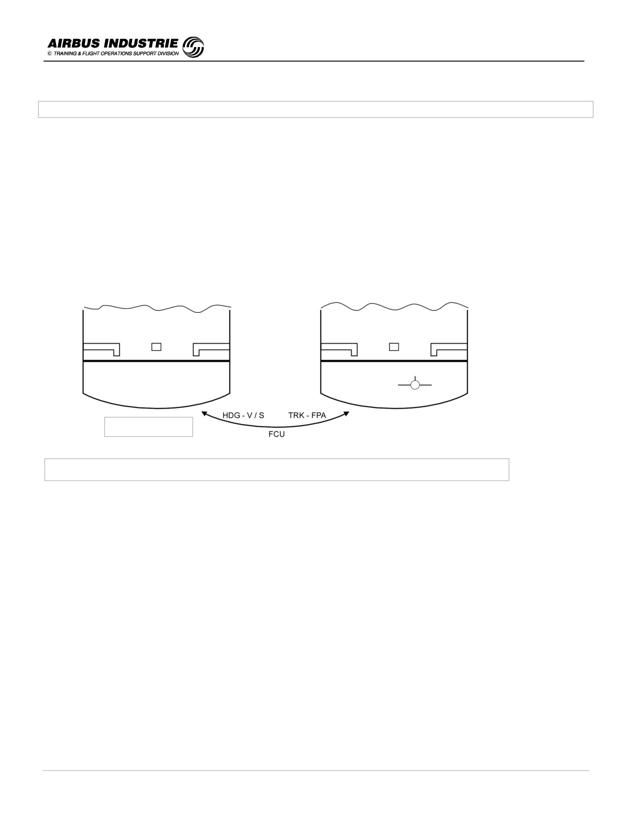
A320 INSTRUCTOR SUPPORT
NORMAL OPERATION
19 - USE OF FLYING REFERENCES - ATTITUDE OR BIRD (FPV)
On the PFD 2 flying references may be selected:
-
The ATTITUDE
-
The FLIGHT PATH VECTOR called BIRD.
The selection is done on the FCU by pressing the P/B identified as HDG - V/S (for ATTITUDE) TRK - FPA (for BIRD).
THE ATTITUDE is a flying reference to be used for DYNAMIC MANEUVERS such as T/O and GO AROUND.
Indeed an action on the stick has an immediate effect on the A/C attitude; thus the pilot can immediately and accurately
control this parameter in those maneuvers.
The BIRD or FLIGHT PATH VECTOR (FPV) represents the A/C trajectory; in dynamic maneuvers it is directly affected
by the A/C inertia. It reacts with a delay. Thus it is difficult to control in dynamic but when the pilot wishes to fly a
STABILIZED SEGMENT OF TRAJECTORY, then the BIRD is well adapted.
FD - Modes
FLYING REFERENCE SELECTION ON THE FCU
When to use the BIRD ?
-
The BIRD may be used in all flight phases, except T/O and GO AROUND.
It is more specifically recommended for NPAs, VISUAL CIRCUITS, VISUAL FLYING.
What to check when pressing the HDG - V/S / TRK - FPA knob ?
-
If you press this P/B, this means that you wish to select the BIRD ON or OFF.
Hence, when you press this P/B, CHECK BIRD ON or BIRD OFF on the PFD.
If the APs/FDs are ON, the internal FG guidance parameters are a function of the flying reference you have selected:
-
If BIRD ON, the basic guidance parameters of AP/FD will be TRK-FPA.
-
If ATTITUDE ON, the basic guidance parameters of AP/FD will be HDG-V/S.
This explains the name of the P/B located on the FCU.
As a consequence if the APs/FDs are in the basic modes HDG - V/S and you select the BIRD ON, the basic modes will
change to TRK - FPA.
In all other cases the modes do not change (e.g. NAV - LOC - CLB - DES - ALT - G/S …).
DATE: JAN 2001
Page 108
UDY0102
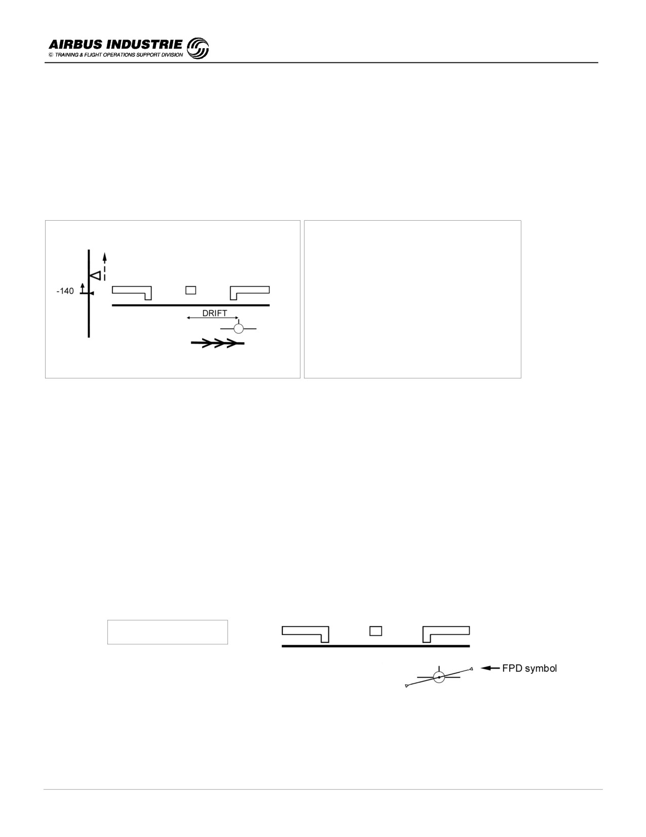
A320 INSTRUCTOR SUPPORT
NORMAL OPERATION
The BIRD is a very efficient flying reference in APPROACH since:
-
It gives the TRAJECTORY PARAMETERS flown by the A/C,
-
It rapidly warns the pilot of WIND DIRECTION changes and
-
It rapidly warns the pilot of DOWNBURST.
Along with the GS MINI target speed, it is an excellent indicator of shears, or wind variations.
Furthermore just by looking at the BIRD versus the center of PFD, the pilot gets immediately the FEELING of the wind
direction; consequently when the A/C reaches MDA, the pilot knows the direction where to search for the runway.
EXAMPLE:
Bird drifts to the right. Hence wind from the
LEFT.
Target approach speed is increasing.
Hence HEADWIND gusts.
BIRD + Target Approach Speed
= Wind Interpretation
The BIRD is computed out of IRS data. It is therefore affected by the errors of the ADIRS.
This is most obvious on the TRK, which, at the end of a flight, may be typically wrong by 1,5° to 2°.
This may be easily determined during the approach.
When FD P/B is set to ON, the Flight Path Director (FPD) symbol is displayed on PFD and referred to the bird. The bird
represents the A/C trajectory (TRK and FPA) and is thus affected by the A/C inertia.
The FPD is also referred to TRK and FPA thus affected by the A/C inertia; this gives the pilot the impression of some
kind of sluggishness of the FPD orders as compared to the orders of the FD crossbars. This is inherent to the BIRD
and FPD type of information.
Thus be smooth when you follow FPD orders.
BIRD ON with PFD
DATE: JAN 2001
Page 109
UDY0102

A320 INSTRUCTOR SUPPORT
NORMAL OPERATION
20 - USE OF AP/FD
These are some highlights regarding the use of AP/FD.
-
The APs/FDs are an assistance to the pilot to fly the aircraft WITHIN the NORMAL FLIGHT envelope in order to
achieve the best performance in T/O, GA, CLB or DES phases. In order to follow the ATC clearances (lateral or
vertical) and in order to fly down and autoland the A/C repetitively with very high accuracy for CAT II and CAT III
conditions.
+ AP can be set ON when the aircraft is within the Flight Envelope (attitude, bank, speed). It automatically goes
OFF, when normal flight envelope is significantly exceeded.
+ Don’t try to engage the AP when it is out of the Flight Envelope; the FBW control laws are there to assist you to
BEST come back within the flight envelope according to your chosen strategy.
-
The APs/FDs operate in MANAGED & SELECTED modes. The choice of the modes is a strategic decision of the
pilot. The pilot chooses Managed modes when he expects the aircraft to fly along the preplanned F.PLN he has
inserted in the MCDU. He chooses Selected modes for specific ATC interventions (e.g. radar vectors), or when
time does not permit to reprogram the FMS to fulfill an ATC clearance.
As a general rule the MANAGED modes may be used when the FMS works properly, which essentially means
that:
• the FMS Navigation Accuracy has been crosschecked and is good, or if GPS available, GPS is primary,
• the ACTIVE F.PLN is meaningful: in other words, the intended lateral & vertical trajectory is inserted, and the
sequencing of the F.PLN is properly monitored.
+ If these 2 conditions are NOT fulfilled, use SELECTED modes and monitor using Raw Data.
-
The 2 main interfaces to AP/FD are the FCU and the MCDU.
• The FCU is the SHORT TERM interface to AP/FD. This means that when you have to achieve a short term
intervention (ATC HDG, expedite, speed etc…). SELECT it on the FCU. You will do it head up and by far more
rapidly.
• The MCDU is the LONG TERM interface to AP/FD. This means that, in most cases except DIR TO. You will
prepare the long term lateral or vertical revisions or you will PRESET SPEEDs for next flight phases on the
MCDU. This is the reason why it is important to use all the facilities available to get prepared for future events
(e.g Preset of speeds, SEC.FPLN, etc.).
If future events are prepared, this allows you to use the MCDU for SHORTER TERM type of interventions such
as LATE CHANGE of RWY, CIRCLING, DIVERSION en ROUTE, or DIVERSION to ALTN.
ANTICIPATE WITH THE FMS
DATE: JAN 2001
Page 110
UDY0102