Robinson Helicopter Company RTR 660 (Number R00015LA). Maintenance Manual (2012) - page 6
Intentionally Blank
Page 96.ii
Chapter 96 Electrical System
CHAPTER 96
ELECTRICAL SYSTEM
96-00 Description
CAUTION
The installation of electrical devices can affect the accuracy
and reliability of the electronic tachometer.
A 28-volt DC electrical system is standard. Primary system components are a sealed lead-acid
battery, a starter-generator, and a generator control unit. The battery is located beneath the
left front seat or in a compartment in the left side of the baggage compartment.
The circuit breaker panel is on the ledge just forward of the left front seat. Breakers are
marked to indicate function and amperage and are of the push-to-reset type.
The battery switch controls the battery relay which connects the battery to the electrical
system. A wire protected by a fuse near the battery bypasses the battery relay to allow the
tachometers and clock to receive battery power with the battery switch OFF.
The avionics switch controls power to avionics. This allows avionics to be switched OFF via
a single switch. Having sensitive electrical equipment off when the generator is switched ON
protects against voltage spikes.
An ammeter indicates total generator output. A digital voltmeter which reads main bus voltage
at the circuit breaker panel is incorporated as part of the OAT indicator. Normal indication is
27.3 to 28.7 volts with the generator ON.
A generator control unit (GCU) controls starter-generator function. Below 58 percent N1 RPM,
the GCU is in start mode regardless of generator switch position. Above 58 percent, the GCU
automatically switches to generate mode. The generator switch should normally be off for
starting to prevent applying generator load to the engine before reaching idle RPM.
If the GEN annunciator illuminates in flight, turn off nonessential electrical equipment and
switch generator to reset (momentary position) and then ON. If the GEN annunciator remains
illuminated, land as soon as practical.
Chapter 96 Electrical System
Page 96.1
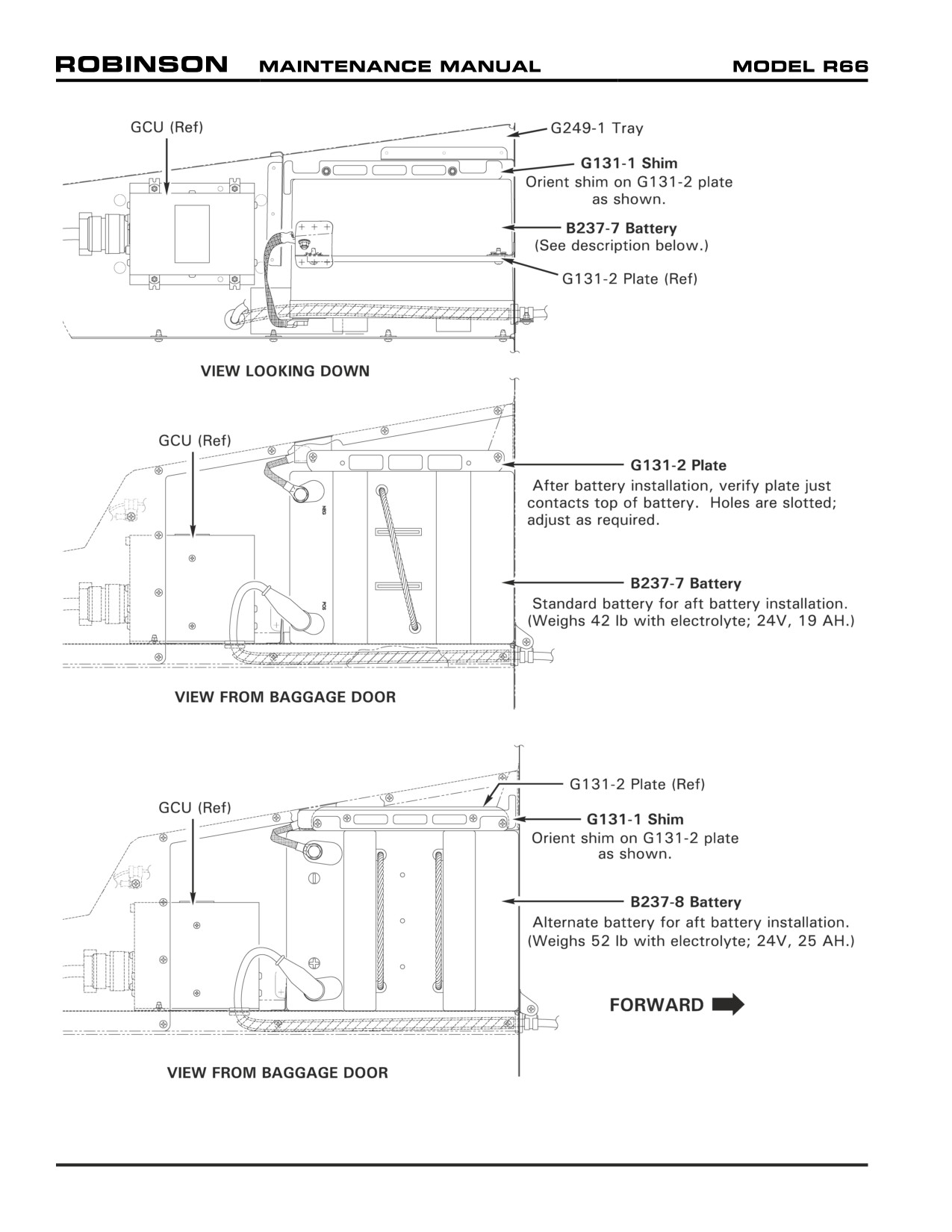
FIGURE 96-1 AFT BATTERY INSTALLATIONS
Page 96.2
Chapter 96 Electrical System
96-10 Battery
NOTE
Refer to Concorde Battery Corporation's Owner/Operator's
Manual, and Instruction for Continued Airworthiness for battery
maintenance procedures.
CAUTION
B237-7 battery (standard; forward and aft) weighs 42 lb and
B237-8 battery (alternate; aft only) weighs
52 lb including
electrolyte. Carefully remove/install battery using handle
provided to prevent injury.
CAUTION
To minimize risk of electrical discharge: When disconnecting
battery, disconnect negative (ground) cable from battery first,
then the positive cable. When connecting battery, connect
positive cable to battery first, then the negative (ground) cable.
A. Disconnecting and Removing Battery
1. Turn BATTERY switch OFF. Refer to Section 6-70.
a. Forward battery: Hinge forward left seat forward and remove F003-11 insulation.
Remove hardware securing F748-1 (battery) cover assembly and remove cover.
b. Aft battery: Open baggage compartment door. Remove hardware securing G248-1
(baggage compartment) cover and remove cover.
2. Remove hardware securing negative (ground) cable to battery negative terminal.
3. Slide nipple away from battery positive terminal and remove hardware securing positive
cable to battery positive terminal. Carefully remove battery.
B.
Installing and Connecting Battery
1. Turn BATTERY switch OFF.
2. a. Forward battery: Hinge forward left seat forward; carefully install B237-7 battery.
b. Aft battery: Open baggage compartment door. Refer to Figure 96-1.
i. If B237-7 battery was removed and B237-8 battery is being installed: Remove
hardware securing G131-1 shim to G249-1 tray and remove shim. Install
hardware securing shim to G131-2 plate as shown. Verify security. Carefully
install B237-8 battery.
ii. If B237-8 battery was removed and B237-7 battery is being installed: Remove
hardware securing G131-1 shim to G131-2 plate. Install hardware securing shim
to G249-1 tray as shown. Verify security. Carefully install B237-7 battery.
iii. If the battery being installed is the same part number as the battery that was
removed: Verify security, proper orientation, and installation of G131-1 shim and
G131-2 plate. Carefully install battery.
Chapter 96 Electrical System
Page 96.3
96-10 Battery (continued)
3.
Verify G131-2 plate just contacts top of battery (holes are slotted). Adjust as required.
4.
Verify battery terminal surfaces are clean to ensure electrical conductivity. Install
positive cable on battery positive terminal and install battery hardware. Special torque
terminal bolt as noted on battery label, and torque stripe per Figure 5-1. Slide nipple
over terminal.
5.
Install negative (ground) cable to battery negative terminal and install battery hardware.
Special torque terminal bolt as noted on battery label, and torque stripe per Figure 5-1.
6.
Refer to Section 6-70.
a. Forward battery: Install F748-1 (battery) cover assembly, and install hardware.
Verify security. Install F003-11 insulation and hinge seat back.
b. Aft battery: Install G248-1 (baggage compartment) cover, and install hardware.
Verify security. Close and latch baggage compartment door.
7.
Aft battery:
a.
If B237-7 battery was removed and B237-8 battery was just installed, revise Weight
and Balance Record in R66 Pilot's Operating Handbook (POH) Section 6 to incorporate
the following data:
Subtract:
Weight
Long. Arm
Long. Moment
Lat. Arm
Lat. Moment
B237-7 Battery
42.00 lb
96.88 in.
4068.96 in.-lb
-20.87 in.
-876.54 in.-lb
Add:
Weight
Long. Arm
Long. Moment
Lat. Arm
Lat. Moment
B237-8 Battery
52.00 lb
96.88 in.
5037.76 in.-lb
-21.73 in.
-1129.96 in.-lb
b.
If B237-8 battery was removed and B237-7 battery was just installed, revise Weight
and Balance Record in R66 Pilot's Operating Handbook (POH) Section 6 to incorporate
the following data:
Subtract:
Weight
Long. Arm
Long. Moment
Lat. Arm
Lat. Moment
B237-8 Battery
52.00 lb
96.88 in.
5037.76 in.-lb
-21.73 in.
-1129.96 in.-lb
Add:
Weight
Long. Arm
Long. Moment
Lat. Arm
Lat. Moment
B237-7 Battery
42.00 lb
96.88 in.
4068.96 in.-lb
-20.87 in.
-876.54 in.-lb
Page 96.4
Chapter 96 Electrical System
96-20 External Power
A 28-volt MS3506-compatible external power receptacle is located inside the right engine cowl
door. When the battery is switched ON, the external power relay and the battery relay both
close, connecting external power to the aircraft electrical system and battery The external
power relay will not close if reverse polarity is provided to the receptacle.
A separate wire from the external power receptacle to the battery bypasses the external
power and battery relays. This wire allows battery charging via the external receptacle with
the battery switch OFF. A 10-amp circuit breaker at the receptacle opens if current exceeds
normal charging levels, and a diode provides polarity protection.
96-30 Starter and Ignition System
A single starter-generator is used for engine starting and electrical power generation. A
generator control unit (GCU) controls starter-generator function. During a start, the GCU
latches the starter on until N1 reaches 58 percent RPM. Therefore, the pilot is not required to
hold the start button down throughout the start sequence. Above 58 percent N1 RPM, the GCU
automatically switches out of start mode, but the generator switch should not be switched ON
until idle RPM stabilizes to prevent the generator load from bringing the RPM down.
When the igniter key switch is in the enable position, depressing the start button causes a
normal start sequence with the starter latching on and the igniter firing. Above 58 percent N1
RPM, the igniter will fire while the start button is depressed.
When the igniter switch is OFF, the engine can be motored by the starter by depressing the
start button without the starter latching or the igniter firing. This is useful for performing
a compressor wash or rinse. If the igniter is switched OFF during a start, the starter will
disengage. If the igniter is switched OFF while the engine is running, the engine will continue
to run; however, this is not recommended.
NOTE
Start button is active when battery switch is ON, even if igniter
switch is OFF. Rotor brake may be left engaged after shutdown
to disable start button.
Chapter 96 Electrical System
Page 96.5
96-40 Lighting System
A red anti-collision light is installed on the tailcone and is controlled by the strobe switch on
the instrument console. Position lights are installed on each side of the cabin and in the tail
and are controlled by the nav lights switch. A light at the top of the windshield and post
lights illuminate the instrument panel. Panel lighting is active when the nav lights switch is
ON and lighting is dimmed via the knob above the nav lights switch. An overhead map light
mounted on a swivel is controlled by an adjacent switch with high and low settings. The map
light may be used for emergency lighting of the instrument panel. An additional cabin light
with an adjacent switch is located just aft of the map light. The map and cabin lights are not
connected to the dimmer circuit.
Two long-life, high intensity discharge (HID) landing lights are installed in the nose. One wide-
angle and one narrow-beam light are used to increase lighted area. The landing light switch is
located on the cyclic center post.
NOTE
Continuous operation of landing and position lights in flight is
recommended to promote collision avoidance.
An optional flashing light may be mounted on the tailcone in addition to the standard anti-
collision light. The optional light is controlled by an additional position on the strobe switch
and may be turned on or off anytime at pilot discretion.
96-50 Annunciator Panel
The annunciator panel consists of illuminated segments located at the top of the main instrument
panel. If a caution or warning condition occurs, the appropriate segment(s) illuminate indicating
the nature of the problem.
The CHIP segments are illuminated by magnetic chip devices in each gearbox which collect
metallic particles in order to complete an electric circuit. The engine gearbox has two magnetic
chip detectors, either of which can illuminate the ENGINE CHIP segment.
The MR TEMP/PRESS segment is illuminated by either the temperature switch or oil pressure
switch at the main gearbox. The ENGINE FIRE segment is illuminated by a temperature switch
in the engine compartment. The ENGINE OIL segment is activated by a pressure switch which
is independent of the oil pressure sender. The ANTI-ICE segment illuminates via a pressure
switch in the engine anti-ice air line. The GEN segment illuminates when the generator is
disconnected from the main electrical bus.
The LOW FUEL segment is illuminated by a float switch in the tank which is independent
of the fuel quantity sender. The FUEL FILTER segment illuminates when a pressure switch
detects excessive pressure drop across the fuel filter. The LOW RPM segment is illuminated
by a sensor measuring driveline speed at the aft end of the main gearbox. A horn sounds
simultaneously with illumination of the LOW RPM segment when rotor speed is below 95%
RPM. The horn is disabled when the collective is fully down.
The COWL DOOR segment is illuminated when the fuel filler cowl door, the right engine cowl
door (which accesses the external power receptacle), or the baggage door is not closed. The
AIR FILTER segment illuminates when pressure drop across the filter opens bypass doors,
allowing unfiltered air to the engine. The EMU (Engine Monitoring Unit) segment indicates the
EMU status with either steady, flashing, or no illumination. The EMU segment will illuminate
only when the test button is depressed.
Page 96.6
Chapter 96 Electrical System
96-50 Annunciator Panel
A push-to-test button on the instrument panel should cause all segments on the annunciator
panel, as well as the ROTOR BRAKE light, to illuminate when depressed. The LOW FUEL
segment takes approximately two seconds before it illuminates due to a time delay in the
circuit.
(The time delay prevents sloshing fuel from giving a false indication.) The EMU
segment takes approximately ten seconds to perform a self-test after the battery is switched
ON before it will illuminate. The test button may be used on the ground or in flight to verify
all circuits are functioning.
96-60 Low Rotor RPM Warning Unit Adjustment
The low rotor RPM warning unit is located inside the upper console, mounted to the left vertical
panel. Two magnets attached to the main gearbox tail rotor driveline output yoke provide an
RPM signal for the warning unit's gearbox-mounted Hall-effect senders. When the collective
is at least 0.2 to 0.4 inch (measured at grip) above the full down position and rotor RPM is
95% or less, the warning unit illuminates the Low RPM annunciator segment and sounds two
warning horns. Fully lowering the collective will silence both horns, but will not extinguish
the annunciator segment. The Low RPM annunciator segment and both horns must remain
off above 95% rotor RPM.
To make an adjustment, remove the plastic plug (from a 3/8-inch diameter hole) in the left-
vertical panel exterior. Adjust screw on back of warning unit (2 turns equals approximately
1% change).
96-70 Audio System
A five-place audio system is standard. An audio control panel allows control of communication
radios, intercom, and stereo-capable auxiliary audio (e.g. music) input.
The system has four modes of operation. In normal mode, all occupants hear incoming and
outgoing radio communications, intercom, and auxiliary audio. The pilot and copilot can both
transmit on the selected radio.
In crew mode, the pilot and copilot are isolated from rear seat occupants. The crew does not
hear rear seat intercom or auxiliary audio and rear seat occupants do not hear crew intercom
or radio communications.
In pilot isolate mode, the pilot is isolated from all other occupants. The copilot is grouped with
the rear seat occupants for intercom and auxiliary audio.
In emergency mode, the pilot transmits and receives on the number one radio only (regardless
of audio panel switch position). All other audio is disabled.
The first three modes are selectable via the audio control panel. Emergency mode occurs if
power to the panel is lost. In addition to the mode control, the audio panel has controls for
squelch, volume, and selection of transmit and receive radios. A detail description of these
controls can be found in the audio system operation manual.
Headset jacks are located in the ceiling near each seat. Pilot and copilot intercom and transmit
are controlled via trigger switches on the cyclic grips. The trigger has two detents; the first
detent activates the intercom and the second detent transmits. Additional intercom buttons
are located on the forward side of the rear seats and on the left forward floor. Intercom may
also be set to be voice activated. Auxiliary audio may be plugged in to a jack on the forward
face of the circuit breaker panel. In normal mode, auxiliary audio is automatically muted during
radio communication.
Chapter 96 Electrical System
Page 96.7
96-80 Engine Monitoring Unit (EMU)
Refer to Section 71-43 for EMU maintenance procedures.
The Engine Monitoring Unit (EMU) is a digital recording device mounted behind the right rear
seatback panel. The EMU continuously monitors N1, N2, engine torque, and MGT. EMU
status is indicated by the EMU segment on the annunciator panel. The EMU segment will
only illuminate while the annunciator panel test button is depressed. The EMU requires
approximately ten seconds to initialize after the aircraft battery is switched ON. Once
initialization is complete, steady illumination of the annunciator means normal EMU operation.
A slowly flashing indication (once every two seconds) is given if the EMU detects a fault in its
senders or circuitry. A fast flashing indication (four times per second) is given if the EMU has
detected an exceedance. A fault or exceedance indication should be investigated and reset by
a qualified mechanic prior to further flight.
The EMU records exceedances of Rolls-Royce engine limits, not airframe operating limits as
given in Section 2. The EMU will record an exceedance if any of the following are exceeded:
MGT during start:
999°C, or 927°C for 1 second, or 810°C for 10 seconds.
MGT engine running:
843°C, or 782°C for 6 seconds, or 706°C for 5 minutes.
N1:
106%, or 105% for 15 seconds.
N2:
110%, or 105% for 15 seconds.
78% to 88% for 60 seconds over 38% torque.
Torque:
122% for 15 seconds, or 104% for 5 minutes.
The EMU also records a start cycle when N1 exceeds 30% and MGT is at least 343°C.
The EMU is intended to be used only as a maintenance aid. It is the pilot's responsibility to
report any observed exceedances and the operator's responsibility to maintain a record of
engine starts and time in service.
96-90 Emergency Locator Transmitter (ELT)
Refer to Section 25-61 for ELT programming instructions and maintenance procedures.
The Emergency Locator Transmitter (ELT) installation consists of a transmitter with internal
battery pack, an external antenna, and a remote switch/annunciator. The transmitter is
mounted to the upper steel tube frame and is accessible through the spring loaded air intake
door in the right-side cowl. The remote switch/annunciator is located left of the cyclic stick.
The ELT is operated by a switch on the transmitter and by the remote switch. The transmitter
switch has been set in the ARM position at installation and should always be in this position
for flight. The remote switch/annunciator is a three position switch with indicator light. This
switch should be in the ARMED position for flight. With both switches set to armed, the ELT
will begin transmitting when subjected to a high "G" load. When the unit is transmitting, the
red indicator light illuminates.
Moving the remote switch to ON activates the transmitter. Use the ON position if an emergency
landing is imminent and time permits.
If the ELT is inadvertently activated, use the momentary RESET & TEST position of the remote
switch to stop transmission and reset the unit. The red indicator will extinguish when unit is
reset.
For more detailed instructions on ELT operation, maintenance, and required tests, refer to
manufacturer's instructions supplied with the unit.
Page 96.8
Chapter 96 Electrical System
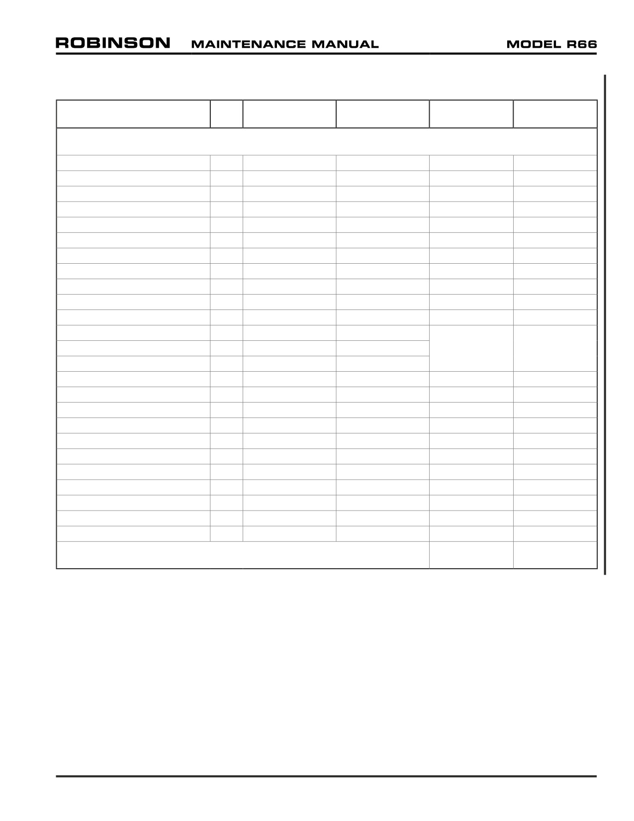
96-100 Electrical Load Analysis
CONTINUOUS
INTERMITTENT
CONTINUOUS
INTERMITTENT
COMPONENT
QTY
AMPS EACH
AMPS EACH
TOTAL
TOTAL
MAIN BUS
WARNING LT PANEL
1
0.006
0.320
0.006
0.320
ROTOR BRAKE LT
1
---
0.044
0.000
0.044
MAPLIGHT
1
0.020
0.020
0.020
0.020
INTERIOR DOME LT
1
0.020
0.020
0.020
0.020
OAT GAGE
1
0.150
0.150
0.150
0.150
ENGINE TORQUEMETER
1
0.050
0.050
0.050
0.050
INSTRUMENT CLUSTER
1
0.375
0.375
0.375
0.375
MOP SENDER
1
0.025
0.025
0.025
0.025
TORQ SENDER
1
0.025
0.025
0.025
0.025
LOW RPM UNIT W/HORN
1
0.045
0.160
0.045
0.160
AA12S-600 AUDIO PANEL
1
1.000
1.000
1.000
1.000
N2 GOVERNOR SYSTEM
1
0.000
0.0871
N2
GOV ACTUATOR @ 12V
1
---
0.150
0.000
0.0871
N2 GOV RELAY @ 12V
1
---
0.010
ANTI-ICE SOLENOID
1
0.670
0.670
0.670
0.670
HEATED PITOT
1
4.000
4.000
4.000
4.000
ENGINE HOUR METER
2
0.015
0.015
0.030
0.030
HYD CONTROL SOLENOID
1
---
0.800
0.000
0.800
ENGINE MONITORING UNIT
1
0.180
0.180
0.180
0.180
AVIONICS RELAY
1
---
0.060
0.000
0.060
LOW FUEL RELAY
1
---
0.010
0.000
0.010
WARNING LIGHT TEST CB
1
---
0.020
0.000
0.020
TACH PWR TEST RELAY
1
---
0.060
0.000
0.060
BOSE HEADSET
5
0.025
0.500
0.125
2.500
AUX POWER PLUG
1
2.000
2.000
2.000
2.000
SUBTOTAL (MAIN BUS)
8.721
12.606
Chapter 96 Electrical System
Page 96.9
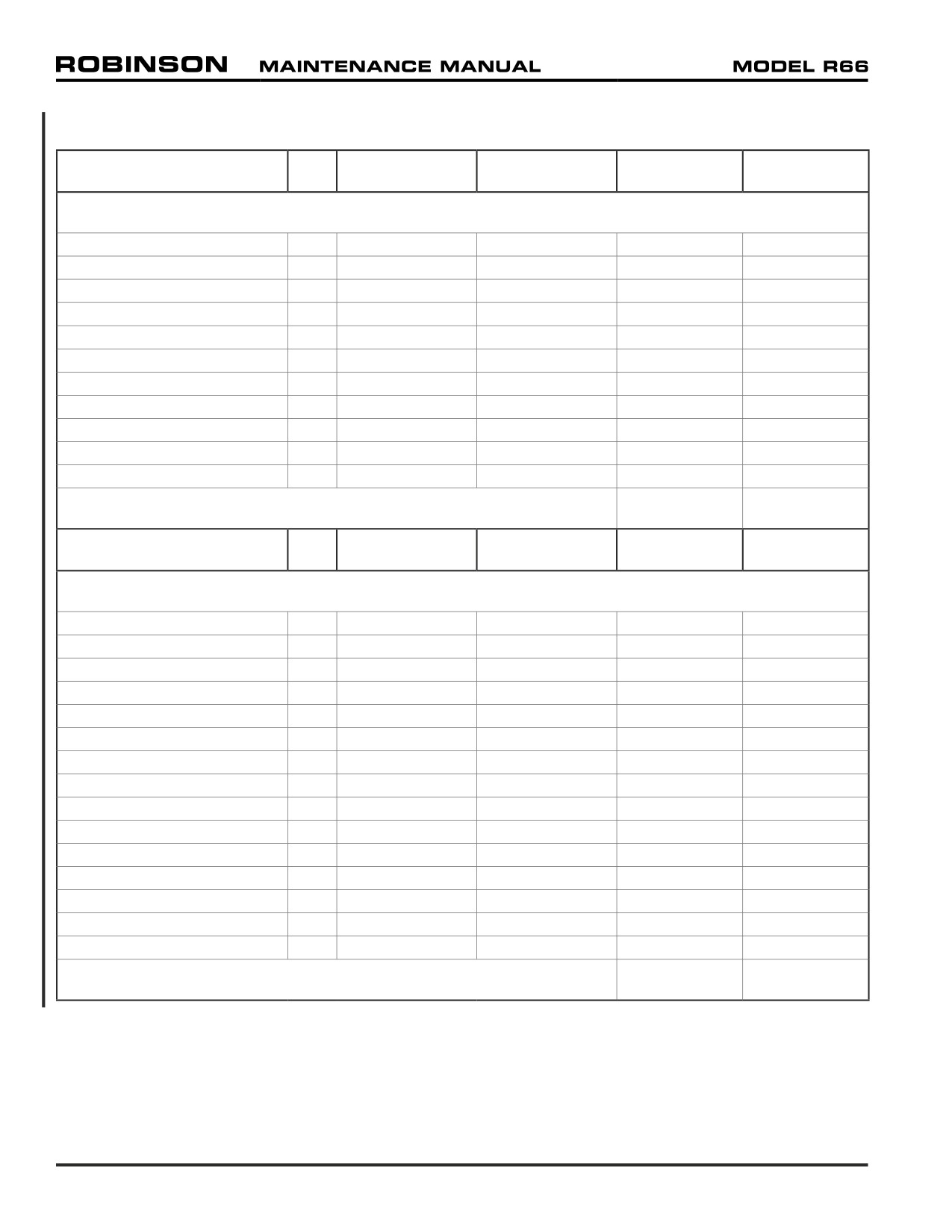
96-100 Electrical Load Analysis (continued)
CONTINUOUS
INTERMITTENT
CONTINUOUS
INTERMITTENT
COMPONENT
QTY
AMPS EACH
AMPS EACH
TOTAL
TOTAL
LIGHTS BUS
LANDING LT BALLAST
2
1.6003
5.2503
3.200
10.500
LANDING LT RELAY
1
0.060
0.060
0.060
0.060
CIRCUIT BREAKER LTS
1
0.0013
0.0013
0.001
0.001
INSTRUMENT LT
1
0.5005
0.5005
0.5005
0.5005
POST LTS
2
0.0401
0.0401
0.080
0.080
INTERNAL AVIONICS LTS
6
0.1001
0.1001
0.600
0.600
VERT CARD COMPASS LT
1
0.0503
0.0503
0.050
0.050
POSITION LT RH (GREEN)
1
0.250
0.250
0.250
0.250
POSITION LT LH (RED)
1
0.250
0.250
0.250
0.250
POSITION LT TAIL (WHT)
1
0.300
0.300
0.300
0.300
STROBE LIGHT
1
0.670
3.000
0.670
3.000
SUBTOTAL (LIGHTS BUS)
5.961
15.591
CONTINUOUS
INTERMITTENT
CONTINUOUS
INTERMITTENT
COMPONENT
QTY
AMPS EACH
AMPS EACH
TOTAL
TOTAL
AVIONICS BUS
KY196A COM
1
1.000
5.000
1.000
5.0002
GNC 420W GPS/COM
1
1.215
4.200
1.215
1.2152
GNS 530AW GPS/COM/NAV
1
1.415
4.400
1.415
1.4152
GTX 330 XPDR
1
1.640
9.090
1.640
9.090
BLIND ENCODER
1
0.600
0.600
0.600
0.600
AM/FM/CD RCVR
1
1.500
1.500
1.500
1.500
KR87 ADF RCVR
1
0.429
0.429
0.429
0.429
KR22 MARKER BEACON
1
0.040
0.500
0.040
0.500
AVIONIC BLOWER
1
0.180
0.180
0.180
0.180
PILOT AV BLOWER
1
0.100
0.100
0.100
0.100
ELT4
1
---
---
---
---
HSI (PICT NAV SYSTEM)
1
1.730
1.730
1.730
1.730
ATTITUDE HORIZON
1
0.270
0.700
0.270
0.700
TURN COORDINATOR
1
0.350
0.350
0.350
0.350
RADAR ALTIMETER
1
0.727
0.727
0.727
0.727
SUBTOTAL (AVIONICS BUS)
11.196
23.536
Page 96.10
Chapter 96 Electrical System
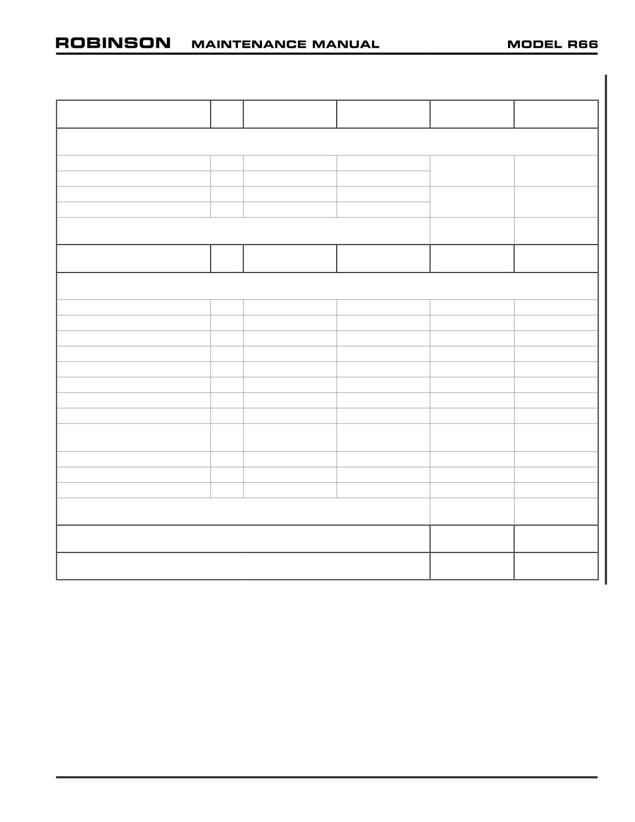
96-100 Electrical Load Analysis (continued)
CONTINUOUS
INTERMITTENT
CONTINUOUS
INTERMITTENT
COMPONENT
QTY
AMPS EACH
AMPS EACH
TOTAL
TOTAL
TACH BUS
N2 TACH (INCL REG)
1
0.0221
0.0221
0.0221
0.0221
N2 TACH @ 13.75V
1
0.035
0.035
ROTOR TACH (INCL REG)
1
0.0221
0.0221
0.0221
0.0221
ROTOR TACH @13.75V
1
0.035
0.035
SUBTOTAL (TACH BUS)
0.044
0.044
CONTINUOUS
INTERMITTENT
CONTINUOUS
INTERMITTENT
COMPONENT
QTY
AMPS EACH
AMPS EACH
TOTAL
TOTAL
OTHER EQUIPMENT
TACH RELAY
1
0.060
0.060
0.060
0.060
CLOCK (DIGITAL)
1
0.003
0.003
0.003
0.003
BATTERY RELAY
1
0.250
6.000
0.250
6.000
START/GEN RELAY
1
0.250
6.000
0.250
6.000
GEN LT RELAY
1
0.010
0.010
0.010
0.010
GEN CONTROL UNIT
1
0.2004
2.0005
0.200
2.000
IGNITION EXCITER
1
---
1.500
0.000
1.500
EXTERNAL PWR RELAY2
1
0.250
6.000
---
---
BAGGAGE COMPARTMENT
1
0.020
0.020
---
---
LT2
SIGHT GLASS LED2
2
0.020
0.020
---
---
LATCHING START RELAY3
1
0.060
0.060
---
---
STARTER-GENERATOR3
1
---
231.06
---
---
SUBTOTAL (OTHER)
0.773
15.573
TOTAL (MAIN + LIGHTS + AVIONICS + TACH + OTHER)
26.70
67.357
STARTER-GENERATOR MARGIN (160-AMP MAX)
+133.30
+92.657
Chapter 96 Electrical System
Page 96.11
Intentionally Blank
Page 96.12
Chapter 96 Electrical System
CHAPTER 98
WIRING DIAGRAMS
Figure Title
Page
98-1
R66 Electrical System (F024 Revision I)
98.1
98-2
R66 Electrical System (F024 Revision G)
98.2
98-3
Air Conditioning Installation
98.3
98-4
ADF Installation
98.5
98-5
Standard Audio System
98.7
98-6
Dual Audio Control Installation
98.9
98-7
PA/Siren Installation
98.11
Chapter 98 Wiring Diagrams
Page 98.i
Intentionally Blank
Page 98.ii
Chapter 98 Wiring Diagrams
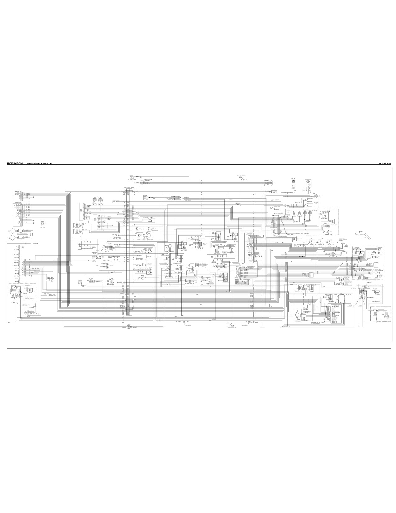
FIGURE 98-1 R66 ELECTRICAL SYSTEM INSTALLATION
(F024 Revision I shown)
Chapter 98 Wiring Diagrams
Page 98.1
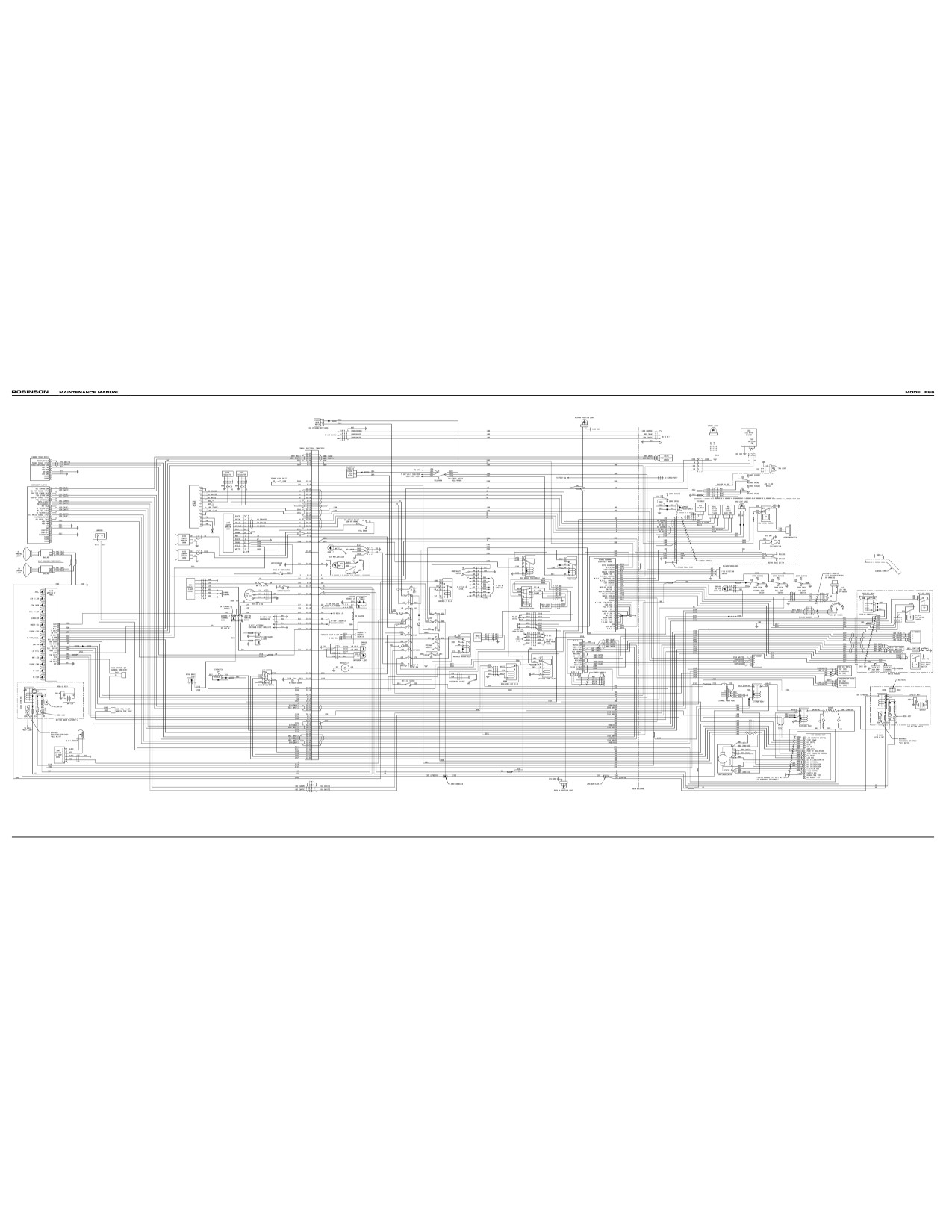
FIGURE 98-2 R66 ELECTRICAL SYSTEM INSTALLATION
(F024 Revision G shown)
Page 98.2
Chapter 98 Wiring Diagrams
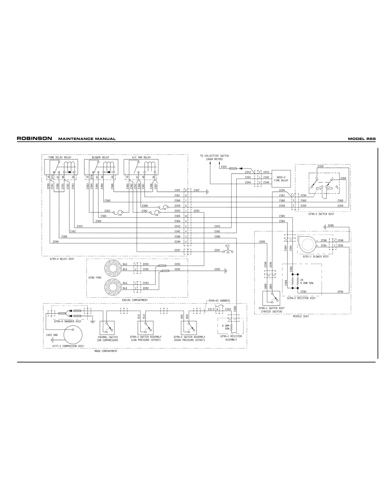
FIGURE 98-3 AIR CONDITIONING INSTALLATION
Chapter 98 Wiring Diagrams
Page 98.3
Intentionally Blank
Page 98.4
Chapter 98 Wiring Diagrams
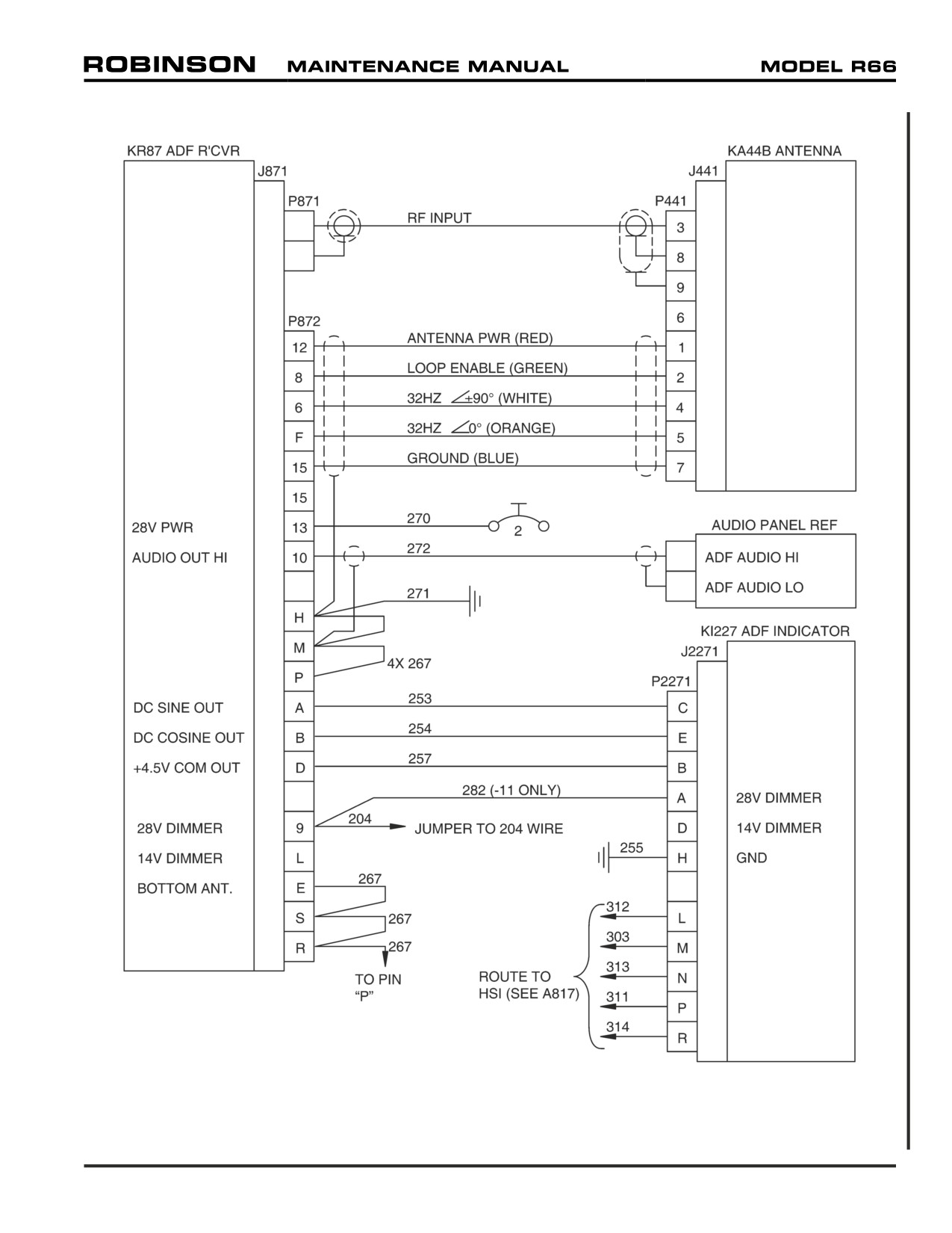
FIGURE 98-4 ADF INSTALLATION
Chapter 98 Wiring Diagrams
Page 98.5
Intentionally Blank
Page 98.6
Chapter 98 Wiring Diagrams
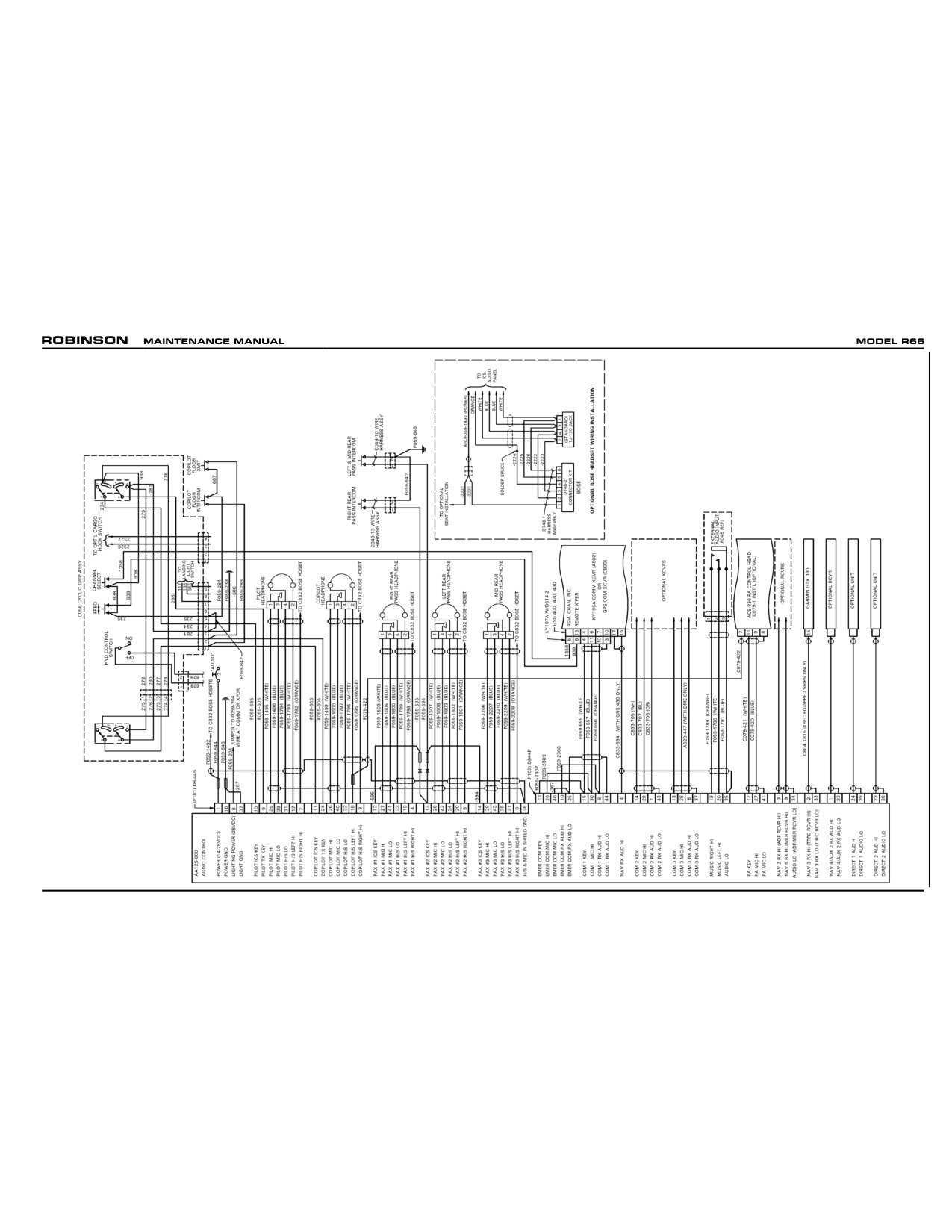
FIGURE 98-5 STANDARD AUDIO SYSTEM
Chapter 98 Wiring Diagrams
Page 98.7
Intentionally Blank
Page 98.8
Chapter 98 Wiring Diagrams
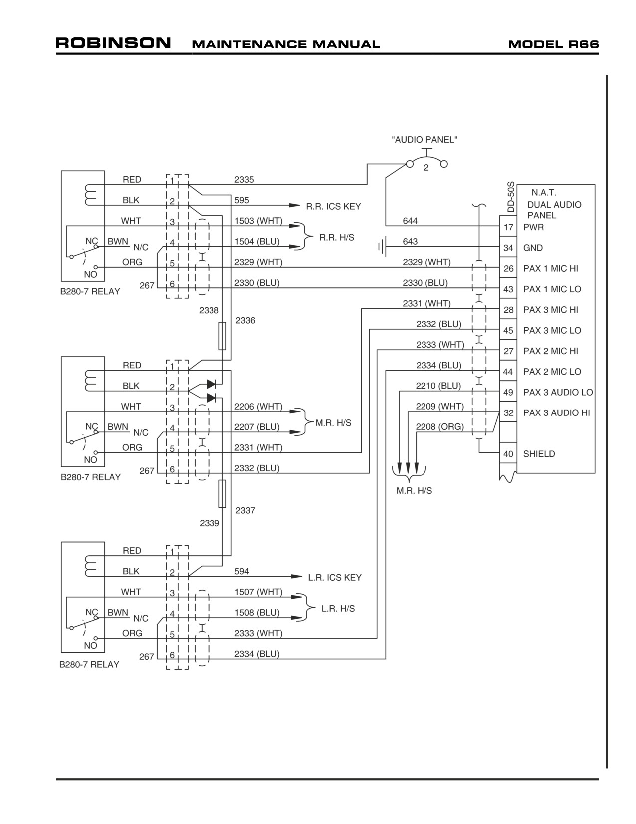
FIGURE 98-6 DUAL AUDIO CONTROL INSTALLATION
Chapter 98 Wiring Diagrams
Page 98.9
Intentionally Blank
Page 98.10
Chapter 98 Wiring Diagrams
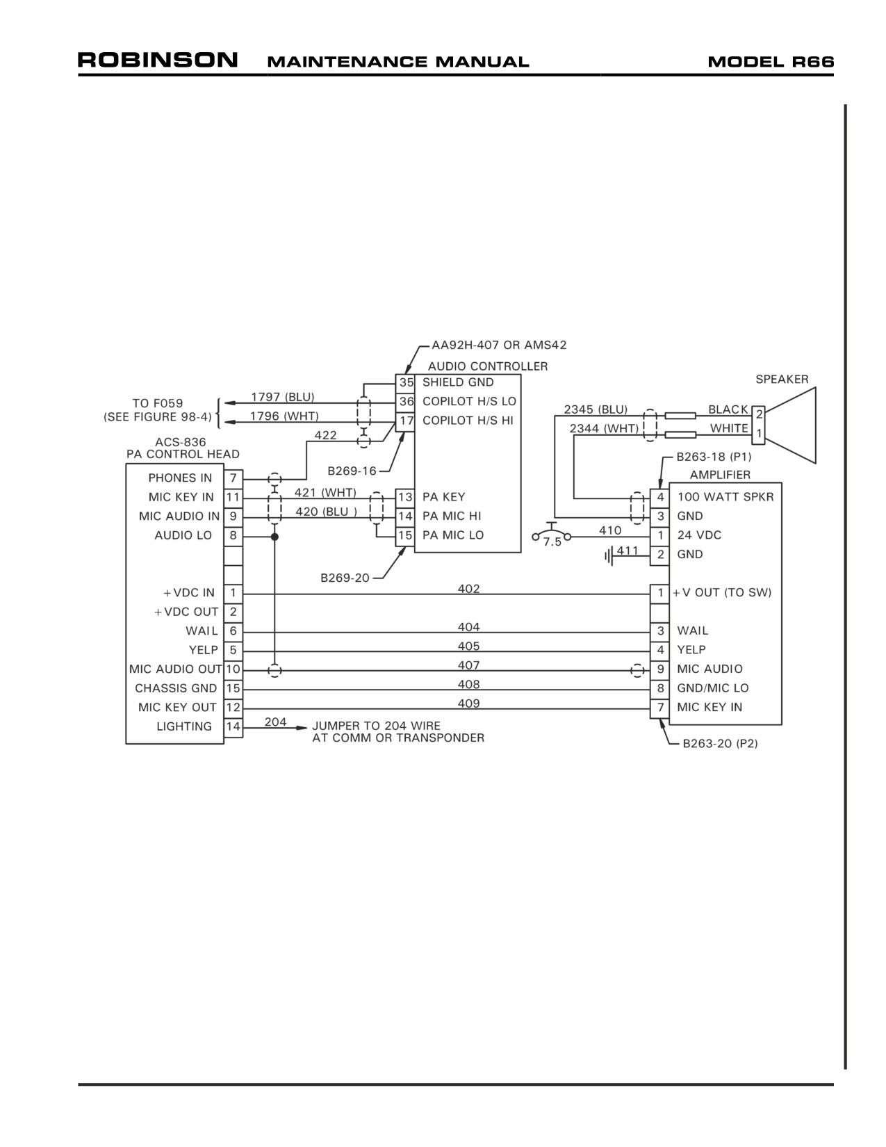
FIGURE 98-7 PA/SIREN INSTALLATION
Chapter 98 Wiring Diagrams
Page 98.11
Intentionally Blank
Page 98.12
Chapter 98 Wiring Diagrams
CHAPTER 99
SPECIAL TOOLS
Section Title
Page
99-10
Special Tools
99.1
99-20
Illustrations and Tasks
99.3
25 OCT 2010
Chapter 99 Special Tools
Page 99.i
Intentionally Blank
Page 99.ii
Chapter 99 Special Tools
25 OCT 2010
CHAPTER 99
SPECIAL TOOLS
99-10 Special Tools
The following is a list of Robinson R66 special tools.
R66 special tools are to be used in conjunction with the applicable instructions for continued
airworthiness, for their designated maintenance task.
25 OCT 2010
Chapter 99 Special Tools
Page 99.1
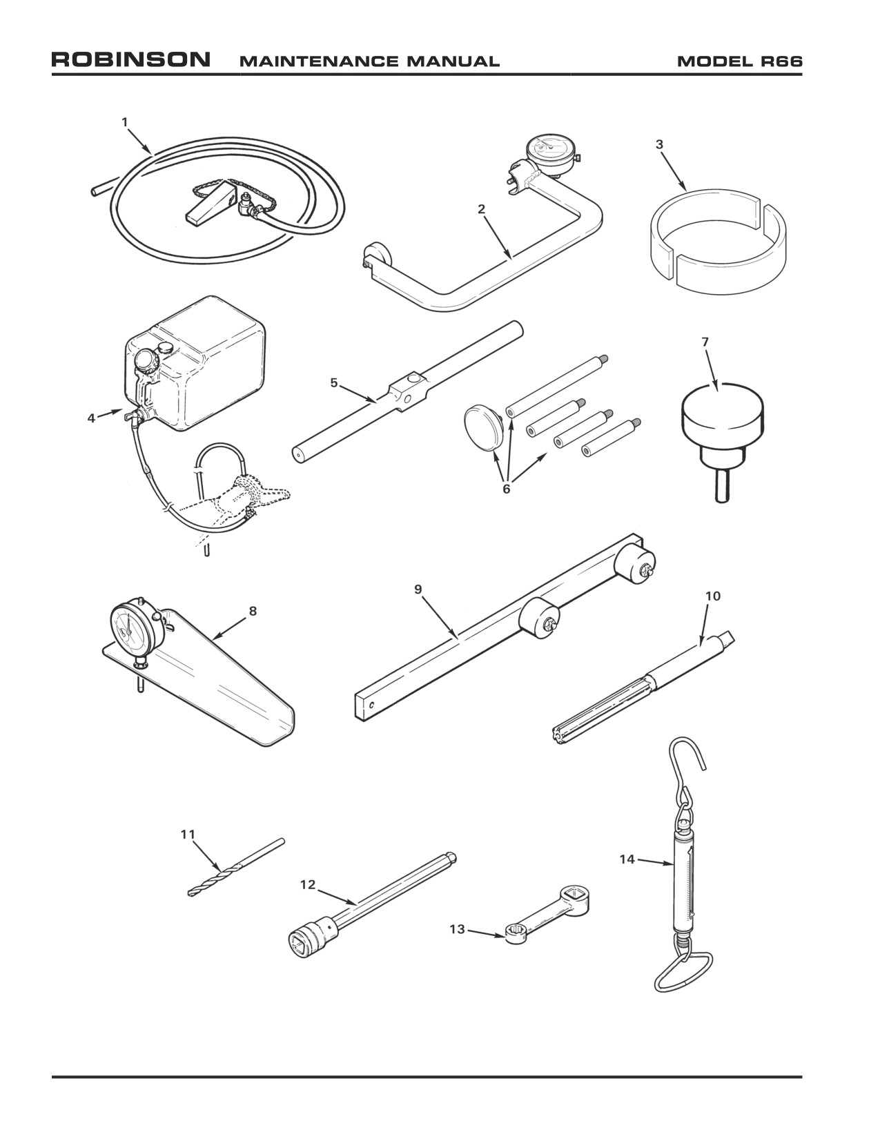
FIGURE 99-1 SPECIAL TOOLS
Page 99.2
Chapter 99 Special Tools
25 OCT 2010
99-20 Illustrations and Tasks
Item
Part No.
Name and Reference Section
1.
MT054-1
Main Rotor Gearbox Drain Assembly - Quick Disconnect
REFER TO SECTION 12-11 MAIN ROTOR GEARBOX SERVICING
2.
MT122-6
Micrometer Assembly - Main Rotor Hub, Bolt Stretch
REFER TO SECTION 62-10 MAIN ROTOR BLADES
3.
MT146-4
Blocks - Swashplate Rigging (set of 2)
REFER TO SECTION 18-30 MAIN ROTOR FLIGHT CONTROL RIGGING
4.
MT147-1
Bleed Tool - Main Rotor Blade Spindle
REFER TO SECTION 12-51 MAIN ROTOR BLADE SPINDLE SERVICING
5.
MT179-4
Balancing Bar - Tail Rotor Assembly Static Balance
REFER TO SECTION 64-11 TAIL ROTOR ASSEMBLY STATIC BALANCE
6.
MT260-6
Tail Rotor Drive Shaft Runout Attachments Kit
REFER TO SECTION 65-21 TAIL ROTOR DRIVE SHAFT RUNOUT
7.
MT329-6
Plug - Main Rotor Hub Bearing Installation
REFER TO SECTION 62-21 MAIN ROTOR HUB BEARING REPLACEMENT
8.
MT352-1
Main Rotor Blade Trim Tab Gage
REFER TO SECTION 18-13 MAIN ROTOR BLADE TRACK ADJUSTMENT
9.
MT354-4
Teeter Moment Tool
REFER TO SECTION 62-32 ADJUSTING HINGE FRICTION
10.
MT357-2
0.375-inch diameter Reamer
VARIOUS; REAM BORE AFTER INSTALLATION OF A139-1 BEARING TO 0.376/0.375-INCH DIA
11.
MT357-3
0.156-inch diameter Steel Drill
REFER TO SECTION 62-33 DRILLING NUTS AND BOLTS
12.
MT357-4
Hex Driver (Snap-On Part No. FABL8)
REFER TO SECTION 65-40 TAIL ROTOR GEARBOX
13.
MT357-5
Torque Adapter (Snap-On Part No. FRDH101)
REFER TO SECTION 65-40 TAIL ROTOR GEARBOX
14.
MT359-1
Spring Scale (0-30 lb)
REFER TO SECTION 62-32 ADJUSTING HINGE FRICTION AND SECTION 67-22 COLLECTIVE FRICTION
15.
MT384-1
Hydraulic Test Pump (U.S / Canada / Mexico - 110-volt)
REFER TO SECTION 12-34 HYDRAULIC SYSTEM BLEEDING
16.
MT384-2
Hydraulic Test Pump (Outside North America - 220-volt)
REFER TO SECTION 12-34 HYDRAULIC SYSTEM BLEEDING
Chapter 99 Special Tools
Page 99.3
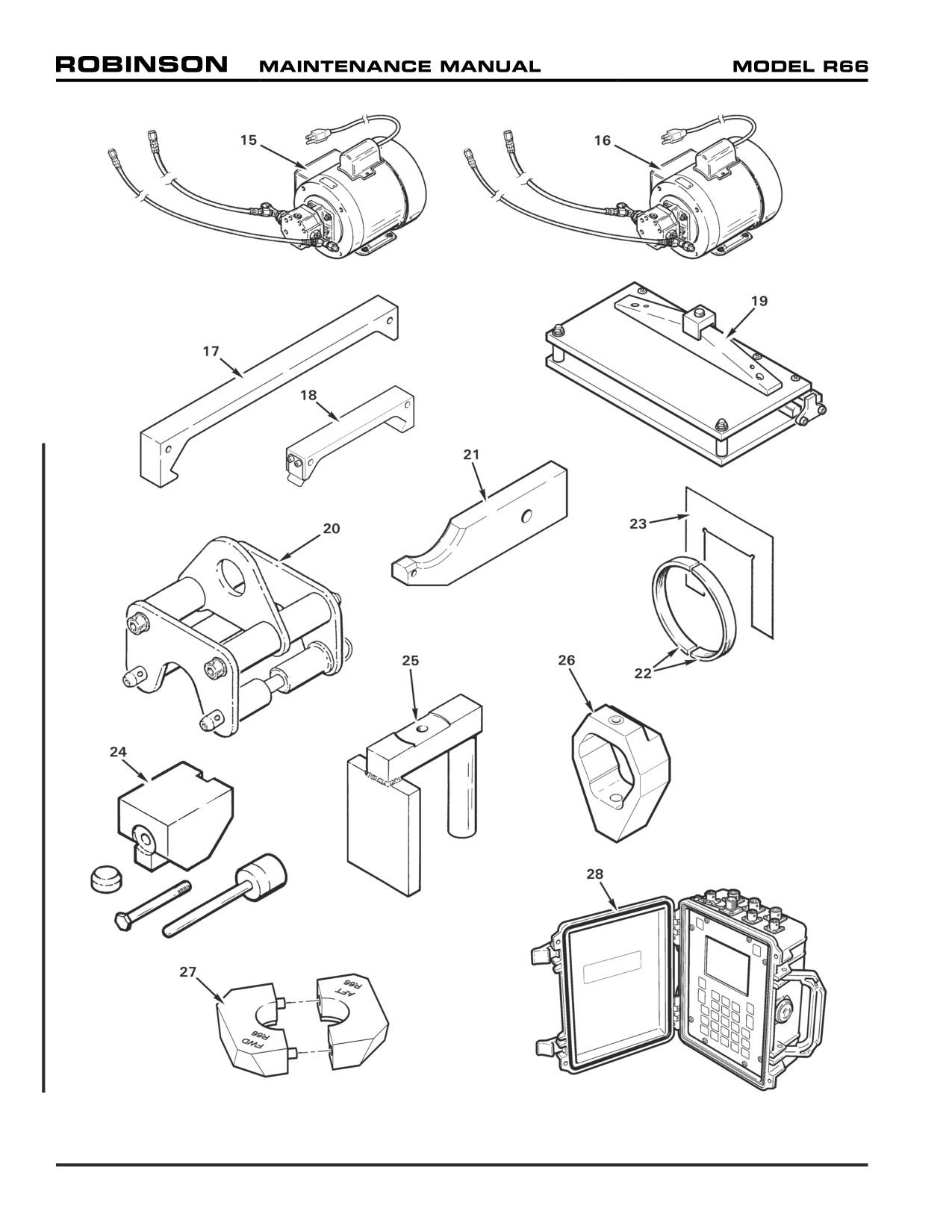
FIGURE 99-2 SPECIAL TOOLS
Page 99.4
Chapter 99 Special Tools
99-20 Illustrations and Tasks (continued)
Item
Part No.
Name and Reference Section
17.
MT525-7
Main Rotor Blade Rigging Fixture
REFER TO SECTION 18-40 MAIN ROTOR BLADE ANGLE RIGGING
18.
MT525-9
Tail Rotor Blade Rigging Fixture
REFER TO SECTION 18-60 TAIL ROTOR BLADE RIGGING
19.
MT526-8
Bender Assembly - Trim Tab, Main Rotor Blade
REFER TO SECTION 18-13 MAIN ROTOR BLADE TRACK ADJUSTMENT
20.
MT527-1
Helicopter Lifting Fixture
REFER TO SECTION 7-20 HOISTING
21.
MT548-8
Fitting (Engine Hoist Adapter)
REFER TO SECTION 71-10 ENGINE
22.
MT549-1
Spacer - Spindle Boot (set of 2)
REFER TO SECTION 62-10 MAIN ROTOR BLADES
23.
MT549-2
Plate - Spindle Boot
REFER TO SECTION 62-10 MAIN ROTOR BLADES
24.
MT556-11
Kit Tools - Tail Rotor Hub Bearing Replacement
REFER TO SECTION 64-41 TAIL ROTOR HUB BEARING REPLACEMENT
25.
MT643-1
Support Weldment - Main Rotor Hub Bearing Installation
REFER TO SECTION 62-21 MAIN ROTOR HUB BEARING REPLACEMENT
26.
MT569-2
Guide Assembly - Drill (main rotor hub nut)
REFER TO SECTION 62-33 MAIN ROTOR ASSEMBLY DRILLING NUTS AND BOLTS
27.
MT759-1
Blocks - Cyclic Rigging
REFER TO SECTION 18-30 MAIN ROTOR FLIGHT CONTROL RIGGING
28.
2020HR
ACES Probalancer Analyzer (or equivalent dynamic balancer)
REFER TO SECTION 18-10 MAIN ROTOR TRACK AND BALANCE
29.
MT850-1
Engine Stand Assembly
REFER TO SECTION 71-10 ENGINE
30.
AN970-4
Washer - Tap Test Tool (or 1965 or later U.S. quarter dollar coin in
good condition; not shown)
REFER TO SECTIONS 62-40 MAIN ROTOR BLADE INSPECTION AND REPAIR AND 64-30 TAIL ROTOR
BLADE INSPECTION AND REPAIR
Chapter 99 Special Tools
Page 99.5
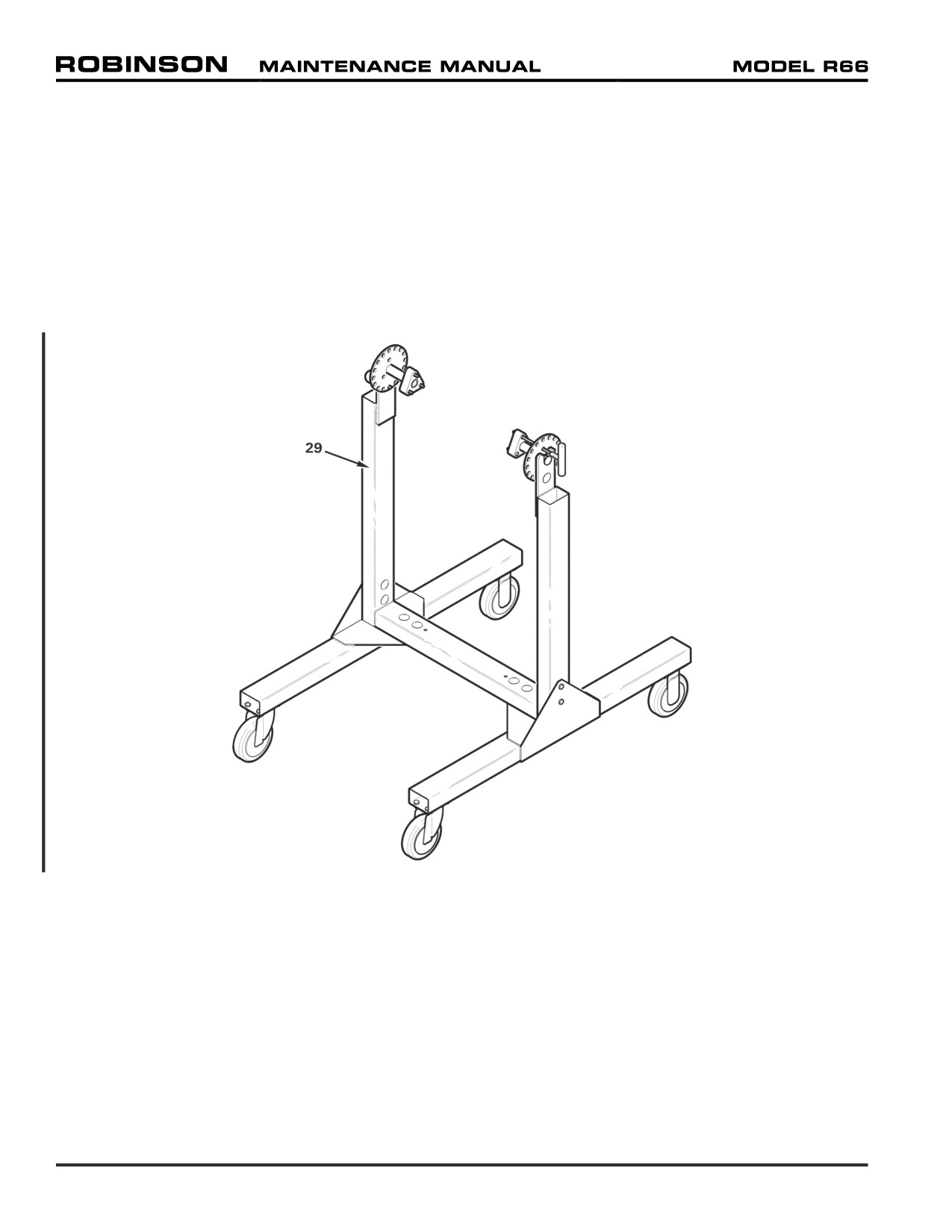
FIGURE 99-3 SPECIAL TOOLS
Page 99.6
Chapter 99 Special Tools
CHAPTER 100
REVISION LOG
Section Title
Page
— Revision Log
100.1
Chapter 100 Revision Log
Page 100.i
Intentionally Blank
Page 100.ii
Chapter 100 Revision Log
REVISION LOG
The R66 Maintenance Manual (MM) list of effective pages and effective dates are given below.
If a previously issued page is not listed below, it is no longer an effective page and must be
discarded. The issue or revision date is in bold at the top of each revision log page.
date is current. A subscription service form is included in the front of this manual.
Page
Date
Page
Date
Page
Date
i
4.ii
25 OCT 2010
5.22
ii
4.1
SEP 2011
5.23
iii
4.2
SEP 2011
5.24
iv
4.3
25 OCT 2010
5.25
v
4.4
25 OCT 2010
5.26
vi
4.5
25 OCT 2010
5.27
vii
4.6
25 OCT 2010
5.28
viii
4.7
25 OCT 2010
5.29
ix
4.8
25 OCT 2010
5.30
x
5.31
xi
5.i
5.32
xii
5.ii
5.33
xiii
5.1
5.34
xiv
5.2
5.35
xv
5.3
5.36
xvi
5.4
5.36A
xvii
5.5
5.36B
xviii
5.6
5.36C
5.7
5.36D
1.i
5.8
5.37
25 OCT
2010
1.ii
5.9
5.38
25 OCT
2010
1.1
5.10
5.39
25 OCT
2010
1.2
5.11
5.40
25 OCT
2010
1.3
5.12
5.41
25 OCT
2010
1.4
5.13
5.42
25 OCT
2010
1.5
5.14
5.43
25 OCT
2010
1.6
5.15
5.44
25 OCT
2010
1.7
5.16
1.8
5.17
6.i
25 OCT 2010
1.9
5.18
6.ii
25 OCT 2010
1.10
5.19
6.1
25 OCT 2010
5.20
6.2
25 OCT 2010
4.i
25 OCT 2010
5.21
6.3
25 OCT 2010
Chapter 100 Revision Log
Page 100.1
REVISION LOG
Page
Date
Page
Date
Page
Date
6.4
25 OCT 2010
9.1
25 OCT 2010
12.12
6.5
25 OCT 2010
9.2
25 OCT 2010
12.13
6.6
25 OCT 2010
9.3
12.14
6.7
25 OCT 2010
9.4
12.15
6.8
25 OCT 2010
12.16
6.9
10.i
25 OCT 2010
12.17
6.10
10.ii
25 OCT 2010
12.18
6.11
10.1
12.19
6.12
10.2
12.20
10.3
25 OCT 2010
7.i
25 OCT 2010
10.4
25 OCT 2010
18.i
7.ii
25 OCT 2010
10.5
25 OCT 2010
18.ii
7.1
10.6
25 OCT 2010
18.1
25 OCT
2010
7.2
18.2
25 OCT
2010
7.3
11.i
18.3
25 OCT
2010
7.4
11.0
18.4
25 OCT
2010
7.5
25 OCT 2010
11.1
18.5
25 OCT
2010
7.6
25 OCT 2010
11.2
18.6
25 OCT
2010
11.3
18.7
25 OCT
2010
8.i
25 OCT 2010
11.4
18.8
25 OCT
2010
8.ii
25 OCT 2010
11.5
18.9
25 OCT
2010
8.1
11.6
18.10
25 OCT
2010
8.2
11.7
18.11
25 OCT
2010
8.3
11.8
18.12
25 OCT
2010
8.4
18.13
25 OCT
2010
8.5
25 OCT 2010
12.i
18.14
25 OCT
2010
8.6
25 OCT 2010
12.ii
18.15
25 OCT
2010
8.7
12.1
18.16
25 OCT
2010
8.8
12.2
18.17
8.9
25 OCT 2010
12.3
18.18
8.10
25 OCT 2010
12.4
18.19
25 OCT
2010
8.11
25 OCT 2010
12.5
18.20
25 OCT
2010
8.12
25 OCT 2010
12.6
18.21
25 OCT
2010
8.13
12.7
18.22
25 OCT
2010
8.14
12.8
18.23
12.9
18.24
9.i
25 OCT 2010
12.10
18.25
9.ii
25 OCT 2010
12.11
18.26
Page 100.2
Chapter 100 Revision Log
REVISION LOG
Page
Date
Page
Date
Page
Date
18.27
21.3
28.9
25 OCT 2010
18.28
21.4
28.10
25 OCT 2010
18.29
21.5
28.11
25 OCT 2010
18.30
21.6
28.12
25 OCT 2010
21.7
20.i
25 OCT
2010
21.8
32.i
20.ii
25 OCT
2010
21.9
32.ii
20.1
25 OCT
2010
21.10
32.1
20.2
25 OCT
2010
21.11
32.2
20.3
25 OCT
2010
21.12
32.3
20.4
25 OCT
2010
21.13
32.4
20.5
21.14
32.5
20.6
32.6
20.7
25.i
32.7
20.8
25.ii
32.8
20.9
25.1
32.9
20.10
25.2
32.10
20.11
25.3
32.11
20.12
25.4
32.12
20.13
25 OCT
2010
25.5
32.13
20.14
25 OCT
2010
25.6
32.14
20.15
25 OCT
2010
25.7
32.15
20.16
25 OCT
2010
25.8
32.16
20.17
25 OCT
2010
25.9
25 OCT 2010
32.17
20.18
25 OCT
2010
25.10
25 OCT 2010
32.18
20.19
25 OCT
2010
25.11
25 OCT 2010
32.19
20.20
25 OCT
2010
25.12
25 OCT 2010
32.20
20.21
32.21
20.22
28.i
25 OCT 2010
32.22
20.23
28.ii
25 OCT 2010
32.23
20.24
28.1
25 OCT 2010
32.24
20.25
25 OCT
2010
28.2
25 OCT 2010
20.26
25 OCT
2010
28.3
25 OCT 2010
52.i
25 OCT 2010
28.4
25 OCT 2010
52.ii
25 OCT 2010
21.i
28.5
25 OCT 2010
52.1
25 OCT 2010
21.ii
28.6
25 OCT 2010
52.2
25 OCT 2010
21.1
28.7
25 OCT 2010
52.3
25 OCT 2010
21.2
28.8
25 OCT 2010
52.4
25 OCT 2010
Chapter 100 Revision Log
Page 100.3
REVISION LOG
Page
Date
Page
Date
Page
Date
52.5
25 OCT 2010
62.3
25 OCT 2010
63.10
52.6
25 OCT 2010
62.4
25 OCT 2010
63.11
52.7
25 OCT 2010
62.5
25 OCT 2010
63.12
52.8
25 OCT 2010
62.6
25 OCT 2010
52.9
25 OCT 2010
62.7
25 OCT 2010
64.i
25 OCT 2010
52.10
25 OCT 2010
62.8
25 OCT 2010
64.ii
25 OCT 2010
52.11
25 OCT 2010
62.9
25 OCT 2010
64.1
25 OCT 2010
52.12
25 OCT 2010
62.10
25 OCT 2010
64.2
25 OCT 2010
62.11
25 OCT 2010
64.3
25 OCT 2010
53.i
25 OCT 2010
62.12
25 OCT 2010
64.4
25 OCT 2010
53.ii
25 OCT 2010
62.13
25 OCT 2010
64.5
25 OCT 2010
53.1
25 OCT 2010
62.14
25 OCT 2010
64.6
25 OCT 2010
53.2
25 OCT 2010
62.15
25 OCT 2010
64.7
25 OCT 2010
53.3
25 OCT 2010
62.16
25 OCT 2010
64.8
25 OCT 2010
53.4
25 OCT 2010
62.17
25 OCT 2010
64.9
25 OCT 2010
53.5
25 OCT 2010
62.18
25 OCT 2010
64.10
25 OCT 2010
53.6
25 OCT 2010
62.19
25 OCT 2010
64.11
25 OCT 2010
53.7
25 OCT 2010
62.20
25 OCT 2010
64.12
25 OCT 2010
53.8
25 OCT 2010
62.21
25 OCT 2010
64.13
25 OCT 2010
53.9
25 OCT 2010
62.22
25 OCT 2010
64.14
25 OCT 2010
53.10
25 OCT 2010
62.23
25 OCT 2010
53.11
25 OCT 2010
62.24
25 OCT 2010
65.i
53.12
25 OCT 2010
62.25
25 OCT 2010
65.ii
53.13
25 OCT 2010
62.26
25 OCT 2010
65.1
53.14
25 OCT 2010
62.27
25 OCT 2010
65.2
53.15
25 OCT 2010
62.28
25 OCT 2010
65.3
53.16
25 OCT 2010
65.4
53.17
25 OCT 2010
63.i
65.5
53.18
25 OCT 2010
63.ii
65.6
53.19
25 OCT 2010
63.1
65.7
53.20
25 OCT 2010
63.2
65.8
53.21
25 OCT 2010
63.3
65.9
53.22
25 OCT 2010
63.4
65.10
63.5
65.11
62.i
25 OCT 2010
63.6
65.12
62.ii
25 OCT 2010
63.7
62.1
25 OCT 2010
63.8
67.i
MAR 2012
62.2
25 OCT 2010
63.9
67.ii
MAR 2012
Page 100.4
Chapter 100 Revision Log
REVISION LOG
Page
Date
Page
Date
Page
Date
67.1
MAR 2012
71.10
95.ii
25 OCT 2010
67.2
MAR 2012
71.11
95.1
25 OCT 2010
67.3
25 OCT 2010
71.12
95.2
25 OCT 2010
67.4
25 OCT 2010
71.13
95.3
25 OCT 2010
67.5
25 OCT 2010
71.14
95.4
25 OCT 2010
67.6
25 OCT 2010
71.15
95.5
25 OCT 2010
67.7
25 OCT 2010
71.16
95.6
25 OCT 2010
67.8
25 OCT 2010
71.17
95.7
25 OCT 2010
67.9
25 OCT 2010
71.18
95.8
25 OCT 2010
67.10
25 OCT 2010
67.11
MAR 2012
75.i
25 OCT 2010
96.i
67.12
MAR 2012
75.ii
25 OCT 2010
96.ii
67.13
MAR 2012
75.1
25 OCT 2010
96.1
67.14
MAR 2012
75.2
25 OCT 2010
96.2
67.15
MAR 2012
96.3
67.15A
MAR 2012
76.i
25 OCT 2010
96.4
67.15B
MAR 2012
76.ii
25 OCT 2010
96.5
67.16
MAR 2012
76.1
96.6
67.17
MAR 2012
76.2
96.7
67.18
MAR 2012
76.3
25 OCT 2010
96.8
67.19
25 OCT 2010
76.4
25 OCT 2010
96.9
67.20
25 OCT 2010
76.5
25 OCT 2010
96.10
67.21
25 OCT 2010
76.6
25 OCT 2010
96.11
67.22
25 OCT 2010
76.7
25 OCT 2010
96.12
67.23
25 OCT 2010
76.8
25 OCT 2010
67.24
25 OCT 2010
98.i
79.i
98.ii
71.i
79.ii
98.1
71.ii
79.1
98.2
71.1
79.2
98.3
71.2
79.3
98.4
71.3
79.4
98.5
71.4
79.5
98.6
71.5
79.6
98.7
71.6
79.7
98.8
71.7
79.8
98.9
71.8
98.10
71.9
95.i
25 OCT 2010
98.11
Chapter 100 Revision Log
Page 100.5
REVISION LOG
Page
Date
Page
Date
Page
Date
98.12
99.i
25 OCT
2010
99.ii
25 OCT
2010
99.1
25 OCT
2010
99.2
25 OCT
2010
99.3
99.4
99.5
99.6
100.i
100.ii
100.1
100.2
100.3
100.4
100.5
100.6
Page 100.6
Chapter 100 Revision Log