Robinson Helicopter Company RTR 660 (Number R00015LA). Maintenance Manual (2012) - page 5
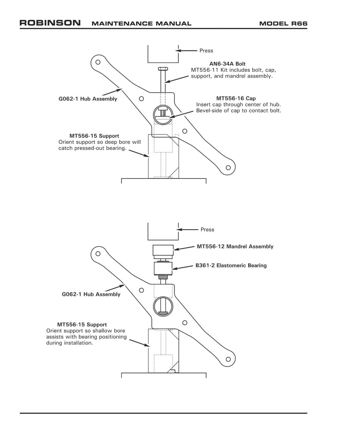
FIGURE 64-5 ELASTOMERIC BEARING REMOVAL
FIGURE 64-6 ELASTOMERIC BEARING INSTALLATION
Page 64.12
Chapter 64 Tail Rotor
25 OCT 2010
64-40 Tail Rotor Hub
64-41 Bearing Replacement
Refer to R66 Illustrated Parts Catalog (IPC) Figure 64-1.
A. Removal
1. Remove tail rotor assembly per Section 64-10.
2. Remove tail rotor blades per Section 64-20.
3. Refer to Figure 64-5. Press bearing(s) from hub using MT556-11 bearing removal
(and installation) tools.
B. Installation
1. Inspect tail rotor hub per Section 64-42.
CAUTION
Elastomeric bearings are a slight press fit in tail rotor hub bores.
Inspect bores for fretting; if fretting is detected, hub is unairworthy.
2. Refer to Figure 64-6. Using Q-tip, apply light coat of approved primer per Section
20-70 to bottom of hub bearing bore. Apply a thin line of primer to center of bearing
outside diameter. While primer is wet, press bearing into hub using MT556-11
bearing removal and installation tools. Wipe away excess primer.
3. Repeat steps for second bearing, as required.
64-42 Inspection
1. Remove tail rotor blades per Section 64-20, and inspect blades per Section 64-30.
2. Remove elastomeric bearings per Section 64-41.
3. Clean G062-1 tail rotor hub using approved solvent per Section 20-70.
4. Visually inspect for indications of damage, wear, nicks, dings, and corrosion. Check
arms for straightness, bolt holes for elongation, and bearing bores for fretting or galling.
Corrosion is not permitted on clamp-up surfaces.
5. For suspect areas, locally remove paint from hub using approved paint stripper per
Section 20-70; dye penetrant or fluorescent penetrant inspect per Section 20-40.
6. Touch-up bare metal using approved materials per Section 20-70.
7. Install elastomeric bearings per Section 64-41.
8. Install tail rotor blades per Section 64-20.
25 OCT 2010
Chapter 64 Tail Rotor
Page 64.13
Intentionally Blank
Page 64.14
Chapter 64 Tail Rotor
25 OCT 2010
CHAPTER 65
TAIL ROTOR DRIVE SYSTEM
Section Title
Page
65-00
Description
65.1
65-10
Tail Rotor Drive Fan Shaft
65.1
65-20
Tail Rotor Drive Shaft Assembly
65.3
65-21
Runout
65.5
65-22
Damper Assembly
65.7
65-30
(Tail Rotor Driveline) Intermediate Flex Plate Shimming
65.8
65-40
Tail Rotor Gearbox Assembly
65.10
65-41
Output Shaft Seal Replacement
65.11
65-42
Input Shaft Seal Replacement
65.12
Chapter 65 Tail Rotor Drive System
Page 65.i
Intentionally Blank
Page 65.ii
Chapter 65 Tail Rotor Drive System
CHAPTER 65
TAIL ROTOR DRIVE SYSTEM
65-00 Description
The tail rotor driveline consists of an intermediate shaft running aft from the main gearbox and
a long tail rotor driveshaft which runs the length of the tailcone. Flexible couplings are located
at both ends of the intermediate shaft. The long tail rotor driveshaft has a support bearing at
its front end and a damper bearing approximately one-third of the way aft on the shaft. The
cooling fan is mounted to the intermediate shaft. The tail gearbox contains a single 90º splash-
lubricated spiral-bevel gearset which increases speed to tail rotor RPM.
65-10 Tail Rotor Drive Fan Shaft
Refer to R66 Illustrated Parts Catalog (IPC) Figure 65-1.
CAUTION
Do not damage F196-1 fan shaft aft yoke or G174-1 fanwheel
assembly mid plate during fan shaft removal or installation.
A. Removal
1. Remove tailcone cowling assembly per Section 53-23.
2. Refer to Figure 65-1. Remove hardware securing F252-1 strut assembly to upper frame
assembly and remove strut.
3. Remove hardware securing intermediate C947-3 flex plate assembly to F196-1 (tail rotor)
fan shaft aft flange and D224-3 tail rotor drive shaft assembly forward yoke, noting
hardware removed. Remove flex plate, and temporarily support aft portion of fan shaft.
4. Remove hardware securing fan shaft to forward C947-3 flex plate assembly.
5. Remove hardware securing fan shaft to G174-1 fanwheel assembly. Carefully pull
fan shaft forward through fanwheel assembly, rotating yoke as necessary. Remove
temporary support.
B.
Installation
1. Refer to Figure 65-1. Route F196-1 fan shaft aft through fanwheel assembly, rotating
yoke as necessary. Install hardware securing fan shaft to G174-1 fanwheel assembly.
Standard torque nuts and palnuts per Section 20-32, and torque stripe per Figure 5-1.
2. Install hardware securing fan shaft to forward C947-3 plate assembly. Standard torque
nuts and palnuts per Section 20-32, and torque stripe per Figure 5-1. Shim tail rotor
driveline per Section 65-30.
3. Install F252-1 strut assembly and hardware securing strut to upper frame assembly.
Standard torque nuts per Section 20-32 and torque stripe per Figure 5-1.
4. Install tailcone cowling assembly per Section 53-23.
Chapter 65 Tail Rotor Drive System
Page 65.1
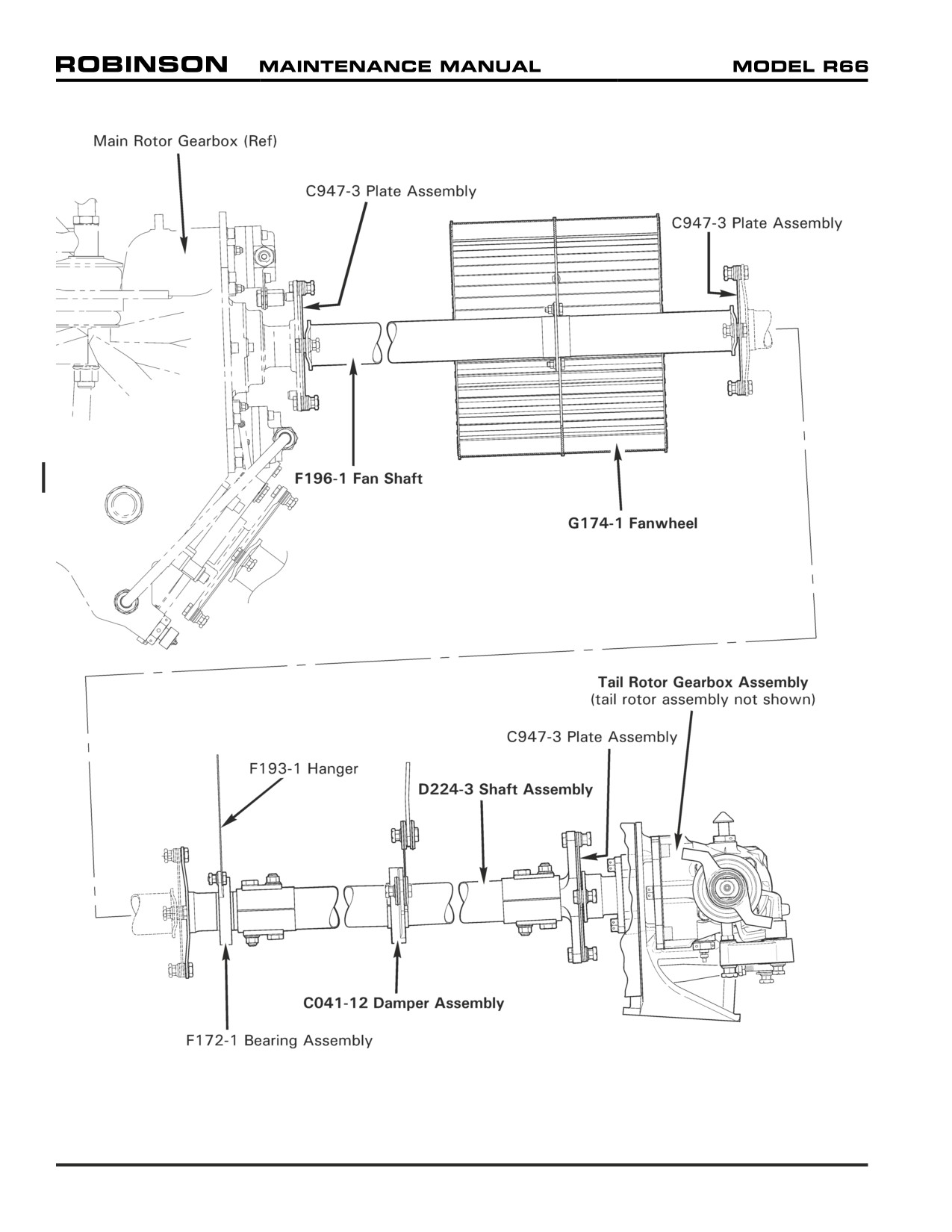
FIGURE 65-1 TAIL ROTOR DRIVELINE
Page 65.2
Chapter 65 Tail Rotor Drive System
65-20 Tail Rotor Drive Shaft Assembly
Refer to R66 Illustrated Parts Catalog (IPC) Figure 65-3.
A. Removal
1. Remove C023 tailcone assembly per Section 53-40.
2. Refer to Figure 65-1. Remove hardware securing F172-1 bearing assembly to F193-1
hanger.
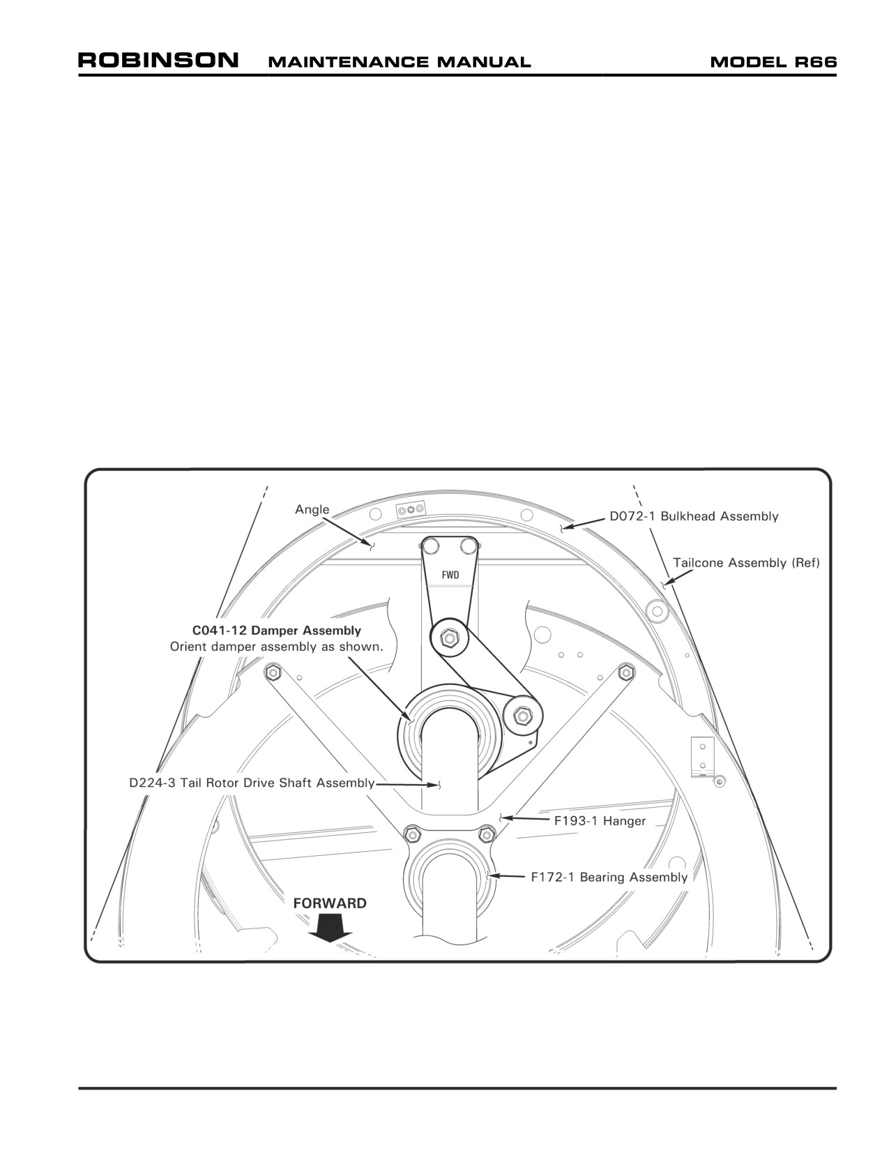
3. Refer to Figure 65-3. Using a 3-foot extension, remove bolts securing C041-12 damper
assembly arm to D072-1 bulkhead assembly angle. Support forward end of D224-3
drive shaft assembly.
4. Remove hardware securing A558-2 cover to tailcone and remove cover.
5. Support aft end of drive shaft, and remove hardware securing drive shaft to aft C947-3
plate assembly, noting hardware removed. Carefully pull drive shaft forward through
tailcone.
B.
Installation
1. Refer to Figure 65-1. Route D224-3 drive shaft assembly through inside of tailcone.
Support drive shaft as required.
2. Install hardware securing drive shaft to aft C947-3 plate assembly, as removed, and
remove support. Standard torque fasteners per Section 20-32 and torque stripe per
Figure 5-1. Install A558-2 cover.
3. Refer to Figure 65-3. Remove forward A231-1 (tailcone) plug assembly. Estimate
longitudinal gap (or interference) between C041-12 damper assembly arm and D072-1
bulkhead assembly angle. If gap (or interference) exceeds 0.12 inch, contact RHC
Technical Support. If gap (or interference) is less than 0.12 inch, verify correct damper
orientation. Using a 3-foot extension, install bolts securing damper to bulkhead angle.
Standard torque bolts per Section 20-32 and torque stripe per Figure 5-1. Install plug
assembly.
4. Install hardware securing F172-1 bearing assembly to F193-1 hanger, and remove
support. Standard torque bolts per Section 20-32 and torque stripe per Figure 5-1.
5. Install C023 tailcone assembly per Section 53-40.
Chapter 65 Tail Rotor Drive System
Page 65.3
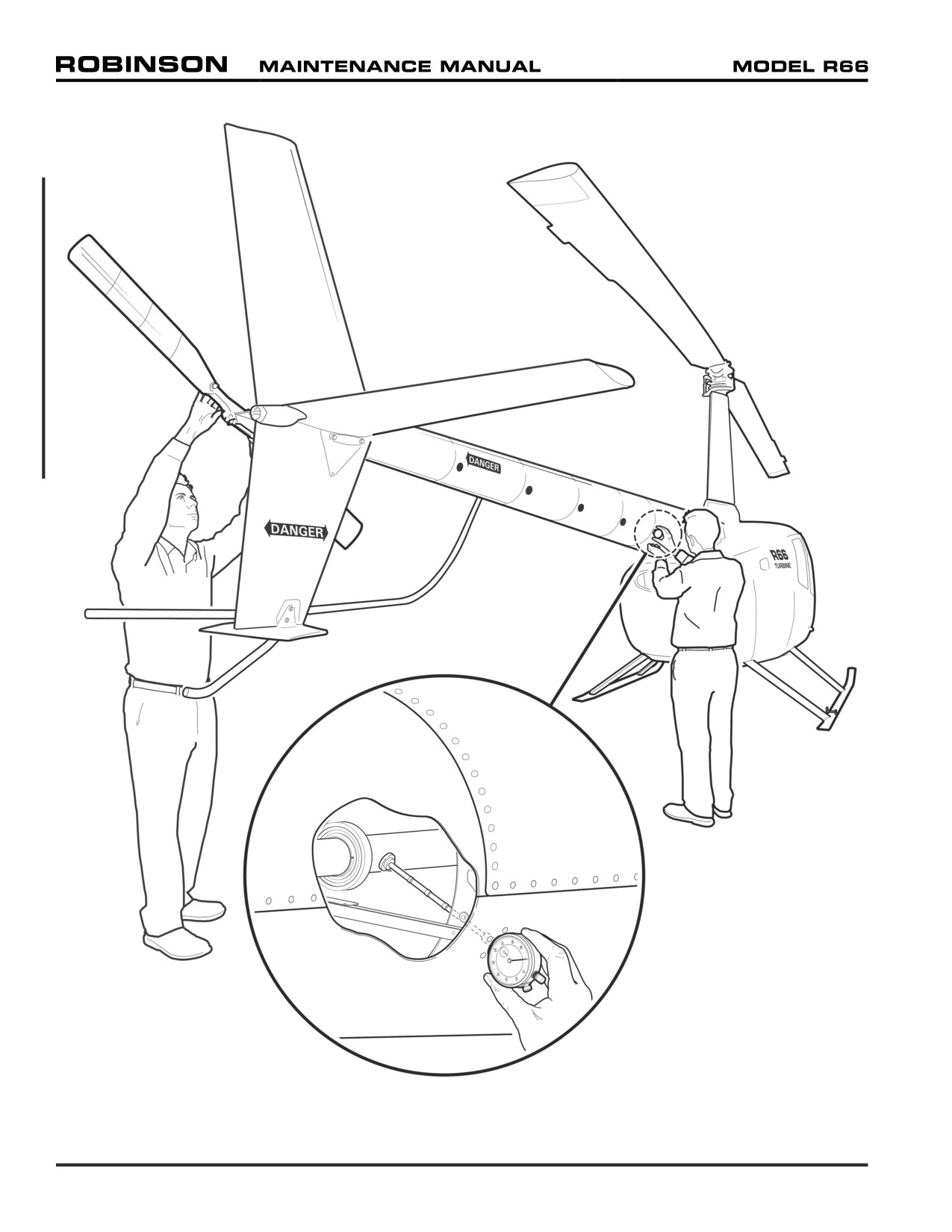
FIGURE 65-2 RUNOUT
Page 65.4
Chapter 65 Tail Rotor Drive System
65-21 Runout
1. Remove (5) A231-1 (tailcone) plug assemblies.
2. Assemble MT260-6 tail rotor drive shaft runout tool and a calibrated dial indicator.
3. Refer to Figure 65-2. Using appropriate combination of extension(s), insert tool through
tailcone inspection hole. Verify foot squarely contacts tail rotor drive shaft when pressing
dial indicator firmly against inspection hole edges. Have a second person rotate rotor
system by turning tail rotor hub.
4. Rotate rotor system slowly, smoothly, and for several revolutions until the technician is
able to determine the average indicated movement. Maximum runout is 0.025 inch.
5. Repeat steps at each inspection hole. Record values as required (recommended during
100-hour or annual inspection).
FIGURE 65-3 DAMPER ORIENTATION
Chapter 65 Tail Rotor Drive System
Page 65.5
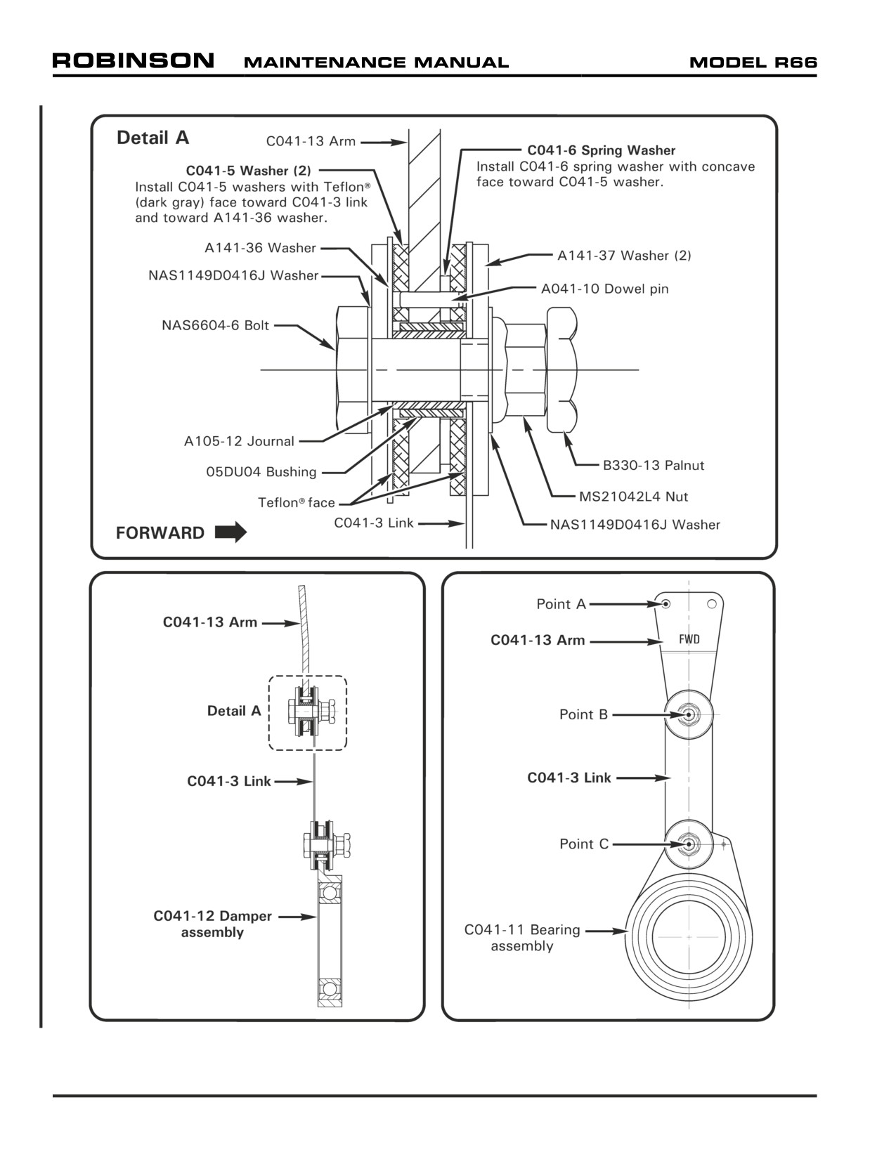
FIGURE 65-4 DAMPER ASSEMBLY
Page 65.6
Chapter 65 Tail Rotor Drive System
65-22 Damper Assembly
Refer to R66 Illustrated Parts Catalog (IPC) Figure 65-7.
A. Disassembly
1. Remove tail rotor drive shaft per Section 65-20, if not previously accomplished.
2. Refer to Figure 65-4. Remove hardware securing C041-11 bearing assembly and
C041-13 arm to C041-3 link.
B.
Inspection and Assembly
1. Refer to Figure 65-4. Inspect condition of components. Verify no wear on Teflon®
(dark gray) face of C041-5 washers. Verify no wear or grooves on A141-36 washers,
A141-37 washers, and link. Replace components as required.
CAUTION
Install C041-5 washers with Teflon® face toward C041-3 link and
toward A141-36 washer (remove protective coating, if installed).
CAUTION
Install C041-6 spring washer with concave face toward C041-5
washer.
2. Assemble damper. Install hardware securing C041-11 bearing assembly and C041-
13 arm to C041-3 link. Align component holes on A041-10 dowel pin(s). Standard
torque nuts and palnuts per Section 20-32 and torque stripe per Figure 5-1.
3. Attach a calibrated spring scale to Point A. Holding link, verify force required to
rotate arm about Point B is 3.5 - 5.8 lb. Adjust as required per Part C.
4. Attach a calibrated spring scale to Point B. Holding bearing assembly, verify force
required to rotate link about point C is 2.1 - 3.6 lb. Adjust as required per Part C.
C. Friction Adjustment
CAUTION
Do not adjust damper drag by changing bolt torque.
1. Refer to Figure 65-4. If friction is less than required:
a. Disassemble C041-12 damper assembly per Part A. Bend C041-6 spring washers
to 0.065 - 0.078 inch total height; inspect and reassemble damper assembly per
Part B.
b. If friction is less than required after correcting spring washer height, disassemble
damper assembly per Part A. Lap A105-12 journals, as required; inspect and
reassemble damper assembly per Part B.
2. If friction is greater than required:
a. Disassemble damper assembly per Part A. Flatten C041-6 spring washers slightly;
inspect and reassemble damper assembly per Part B.
3. Install tail rotor drive shaft per Section 65-20.
Chapter 65 Tail Rotor Drive System
Page 65.7
65-30 (Tail Rotor Driveline) Intermediate Flex Plate Shimming
NOTE
The tail rotor driveline is shimmed for minimal preload.
1.
Refer to Figure 65-1. If not previously accomplished, remove hardware securing
intermediate C947-3 flex plate assembly to F196-1 (tail rotor) fan shaft aft flange and
D224-3 tail rotor drive shaft assembly forward yoke. Remove flex plate, and temporarily
support aft portion of fan shaft.
2.
Measure flex plate thickness at bonded washers (4 places) to determine average thickness:
(1st place)
inch
(2nd place) +
inch
(3rd place) +
inch
(4th place) +
inch
Total =
inch
Total ÷ 4 =
inch
(Flex plate average thickness)
3.
a.
Position F196-1 fan shaft aft flange arms and D224-3 tail rotor drive shaft assembly
forward yoke flange arms at 3 o’clock and 9 o’clock positions (horizontal). Measure
gap between arms to determine average gap:
(3 o’clock position)
inch
(9 o’clock position) +
inch
Total =
inch
Total ÷ 2 =
inch
(Average gap between flange arms)
b.
Rotate D224-3 tail rotor drive shaft assembly 180º, and repeat step a:
(3 o’clock position)
inch
(9 o’clock position) +
inch
Total =
inch
Total ÷ 2 =
inch
(Average gap between flange arms)
4.
Evaluate flange straightness by calculating the difference between the 3 o’clock positions
in steps 3a and 3b. Also calculate the difference between the 9 o’clock positions in
steps 3a and 3b. If either calculated difference exceeds 0.015 inch, either one or both
flanges are bent and require replacement.
Page 65.8
Chapter 65 Tail Rotor Drive System
65-30 (Tail Rotor Driveline) Intermediate Flex Plate Shimming (continued)
5. Using the smaller average gap from step 3a or 3b, subtract the flex plate average
thickness determined in step 2:
Smaller average gap between flange arms (step 3a or 3b)
inch
Subtract flex plate average thickness (step 2) −
inch
Total =
inch
6. Select shims per Table 65-1 and install intermediate C947-3 flex plate assembly.
Standard torque nuts and palnuts per Section 20-32 and torque stripe per Figure 5-1.
Remove F196-1 (tail rotor) fan shaft temporary support.
WARNING
Shim both arms of flanges equally. All fasteners must meet
torque requirements given in Section 20-33.
Shim required between
Shim required between
Calculated
intermediate C947-3 flex plate
intermediate C947-3 flex plate
Dimension
and D224-3 tail rotor drive shaft
and F196-1 fan shaft aft flange
forward yoke
NAS1149F0432P washer between forward C947-3 flex plate
assembly and F908-1 yoke assembly and/or F196-1 fan shaft
−0.017 or greater
forward flange may be relocated under nut as required to achieve
negative number
−0.016 / +0.016 inch calculated dimension. Relocate washers as
required, and repeat steps 3 thru 6.
−0.016 / +0.016 in.
None
None
+0.017 / +0.047 in.
NAS1149F0432P washer
None
+0.048 / +0.079 in.
NAS1149F0432P washer
NAS1149F0432P washer
+0.080 / +0.110 in.
NAS1149F0463P washer
NAS1149F0432P washer
+0.111 / +0.141 in.
NAS1149F0463P washer
NAS1149F0463P washer
NAS1149F0432P washer between forward C947-3 flex plate
assembly and F908-1 yoke assembly and/or F196-1 fan shaft
+0.142 or greater
forward flange may be exchanged with NAS1149F0463P washer as
positive number
required to achieve −0.016 / +0.016 inch calculated dimension.
Exchange washers as required, and repeat steps 3 thru 6.
TABLE 65-1 TAIL ROTOR DRIVELINE
7. Measure fanwheel-to-inlet gaps per Section 79-11.
Chapter 65 Tail Rotor Drive System
Page 65.9
65-40 Tail Rotor Gearbox Assembly
Refer to R66 Illustrated Parts Catalog (IPC) Figure 65-9.
A. Removal
NOTE
Drain tail rotor gearbox oil per Section12-21 prior to gearbox
removal, or keep gearbox vertical after removal to avoid oil
escape thru filler-vent plug.
1. Remove hardware securing push-pull tube assembly to bellcrank assembly.
2. As required, remove tail rotor assembly per Section 64-10. As required, remove hardware
securing bellcrank to tail rotor gearbox assembly output cartridge. Slide (assembled)
bellcrank, pitch control assembly, and pitch links off of gearbox output shaft.
3. Remove hardware securing A558-2 cover to tailcone and remove cover.
4. Support aft end of D224-3 drive shaft assembly, and remove hardware securing gearbox
input yoke to aft C947-3 plate assembly, noting hardware removed.
5. Cut and discard ty-raps as required and disconnect chip detector wiring at plastic
connector.
6. Remove hardware securing gearbox to tailcone casting and remove gearbox.
B.
Installation
1. Position tail rotor gearbox assembly on tailcone casting and install mounting hardware.
Special torque screws per Section 20-33 and torque stripe per Figure 5-1.
2. Connect chip detector wiring at plastic connector and install ty-raps, as required. Cinch
ty-raps until snug without over-tightening, and trim tips flush with heads.
3. Install hardware securing gearbox input yoke to aft C947-3 plate assembly, and remove
support. Shim tail rotor driveline per Section 65-30. Standard torque bolts per Section
20-32 and torque stripe per Figure 5-1. Install A558-2 cover.
4. If removed, slide (assembled) bellcrank assembly, pitch control assembly, and pitch
links onto gearbox output shaft. Install hardware securing bellcrank to gearbox output
cartridge. Standard torque bolts per Section 20-32 and torque stripe per Figure 5-1.
Shim pitch control per Section 67-62, as required.
5. Install hardware securing push-pull tube assembly to bellcrank. Standard torque fastener
per Section 20-32 and torque stripe per Figure 5-1.
6. If removed, install tail rotor assembly per Section 64-10.
7. Service tail rotor gearbox per Section 12-21, as required.
Page 65.10
Chapter 65 Tail Rotor Drive System
65-41 Output Shaft Seal Replacement
Refer to R66 Illustrated Parts Catalog (IPC) Figure 65-13.
1.
Remove tail rotor assembly per Section 64-10.
2.
Remove hardware securing push-pull tube assembly to bellcrank assembly.
3.
Remove hardware securing bellcrank to tail rotor gearbox assembly output cartridge.
Slide (assembled) bellcrank, pitch control assembly, and pitch links off of gearbox output
shaft.
4.
Cut and discard safety wire securing C112-2 cap retaining hardware. Remove hardware
securing cap to gearbox and remove cap with C966-2 seal and C215-133 o-ring.
CAUTION
Do not remove shims between cap and gearbox assembly.
Shims control output shaft drag.
5.
Using hydraulic press, press old seal from cap. Remove and discard o-ring. Clean and
dry cap, especially seal seating surface and o-ring groove.
6.
Verify open face of seal points toward gearbox and press new seal into cap bore 0.160
inches from external surface. Lightly coat new o-ring with A257-22 oil and install in
cap.
7.
Lightly coat output shaft seal seating area with A257-22 lubricant and slide cap onto
shaft. Install hardware securing cap to gearbox and special torque bolts per Section 20-
33. Install 0.032-inch diameter lockwire through hardware and safety in pairs.
8.
Slide (assembled) bellcrank assembly, pitch control assembly, and pitch links onto
gearbox output shaft. Shim pitch control per Section 67-62, as required.
9.
Install hardware securing push-pull tube assembly to bellcrank. Standard torque fastener
per Section 20-32 and torque stripe per Figure 5-1.
10.
Install tail rotor assembly per Section 64-10.
Chapter 65 Tail Rotor Drive System
Page 65.11
65-42 Input Shaft Seal Replacement
Refer to R66 Illustrated Parts Catalog (IPC) Figure 65-13.
1.
Remove tail rotor gearbox per Section 65-40. Tail rotor assembly and pitch control
assembly removal are not required.
2.
Remove and discard cotter pin securing tail rotor input yoke retaining nut. On a suitable
work bench, place a wood block between yoke and gearbox housing to prevent tail rotor
rotation; remove castellated nut, washer, and yoke.
3.
Cut and discard safety wire securing C112-1 cap retaining hardware. Remove hardware
securing cap to gearbox and remove cap with A966-3 seal and C215-140 o-ring.
CAUTION
Do not remove C141-2 washer between cap and bearing.
4.
Using hydraulic press, press old seal from cap. Remove and discard o-ring. Clean and
dry cap, especially seal seating surface and o-ring groove.
5.
Verify open face of seal points toward gearbox and press new seal into cap bore 0.25
inch from external surface. Lightly coat new o-ring with A257-22 oil and install in
cap.
6.
Install cap, and hardware securing cap to gearbox; special torque bolts per Section 20-
33. Install 0.032-inch diameter lockwire through hardware and safety in pairs.
7.
Install input yoke, washer, and castellated nut onto gear shaft. Place wood block
between yoke and gearbox housing to prevent tail rotor rotation, special torque nut per
Section 20-33, and install new MS24665-210 cotter pin.
8.
Install tail rotor gearbox per Section 65-40.
Page 65.12
Chapter 65 Tail Rotor Drive System
CHAPTER 67
FLIGHT CONTROLS
Section
Title
Page
67-00
Description
67.1
67-10
Cyclic Controls
67.1
67-11
Cyclic Control Assembly
67.1
67-12
Cyclic Grip Assembly
67.4
67-13
Cyclic Friction Assembly
67.6
67-20
Collective Control
67.6
67-21
Collective Stick Assembly
67.6
67-22
Collective Friction
67.8
67-30
Jackshaft and Strut Assembly
67.8
67-31
Jackshaft
67.8
67-40
Swashplate
67.9
67-41
Swashplate Tilting Friction Adjustment
67.11
67-42
Upper and Lower Scissor Assemblies
67.11
67-50
Hydraulic System
67.13
67-51
Hydraulic Pump
67.13
67-52
Hydraulic Reservoir
67.14
67-53
Hydraulic Servos
67.15B
67-60
Tail Rotor Controls
67.19
67-61
Pedals
67.19
67-62
Pitch Control
67.20
67-70
Bellcranks
67.21
67-71
C317-5 Bellcrank
67.21
67-72
C317-7 Bellcrank
67.22
67-73
F316-1 Bellcrank
67.22
67-74
A331-4 Bellcrank
67.23
67-75
A120-5 Bellcrank
67.24
MAR 2012
Chapter 67 Flight Controls
Page 67.i
Intentionally Blank
Page 67.ii
Chapter 67 Flight Controls
MAR 2012
CHAPTER 67
FLIGHT CONTROLS
67-00 Description
Dual controls, which are removable on the left side, are standard equipment. All primary
controls are actuated through push-pull tubes and bellcranks. Bearings used throughout the
control system are either sealed ball bearings or have self-lubricated Teflon® liners.
R66 flight controls operate conventionally. The cyclic stick appears different, but the grip
moves the same as in other helicopters due to the free hinge at the center pivot. The cyclic
grip is free to move vertically allowing the pilot to rest his forearm on his knee if he chooses.
The collective control is also conventional. A twist grip provides input to the engine fuel
control, and raising or lowering the collective provides power turbine governor inputs via an
interconnecting linkage.
Pilot-side tail rotor pedals are adjustable. To adjust, extract quick-release pin on each pedal by
depressing button and pulling. Slide pedal fore or aft to most comfortable of three adjustment
positions, and reinstall quick-release pin. Verify pins secure before flight.
See R66 Pilot's Operating Handbook (POH) Section 7 for instructions to remove (removable)
flight controls.
See Section 67-50 for hydraulic system description.
WARNING
Assembly of flight controls is critical and requires inspection
by a qualified person. If a second person is not available, the
installer must take a 5-minute break prior to inspecting flight
control connections he has assembled.
67-10 Cyclic Controls
Refer to R66 Illustrated Parts Catalog (IPC) Chapter 67.
67-11 Cyclic Control Assembly
A. Removal
1. Refer to Section 6-70. Remove F794-1 (forward) and F794-2 (aft) belly panels,
F680-3 (pilot collective) and F445-1 (forward tunnel) cover assemblies, and F461-1
(collective cross tube) and F463-1 (aft tunnel) cover assemblies. Open upper console,
disconnect OAT gage and hourmeter wiring connectors, and remove radio faceplate.
Remove plastic hole plug from vertical keel panel beneath RH, aft seat.
2. Turn cyclic friction OFF. Gently punch out cyclic friction knob spring pin and remove
knob. Remove hardware securing F444-1 cover assembly to F338-1 box, unsnap
boot, and lift cover assembly to expose wire harness connectors. Disconnect anti-
ice, pitot heat, and ELT switch (if installed) wiring. Snap boot together at top of
cyclic stick to secure cover. Install pin on cyclic friction shaft to retain spacers.
3. Refer to Figure 67-1. Unhook D918-1 cord assembly from C069-8 (cyclic) stick
assembly and D918-2 cord assembly from C177-5 pivot assembly.
4. Disconnect wiring exiting D320-8 stick at connectors near bottom of stick.
MAR 2012
Chapter 67 Flight Controls
Page 67.1
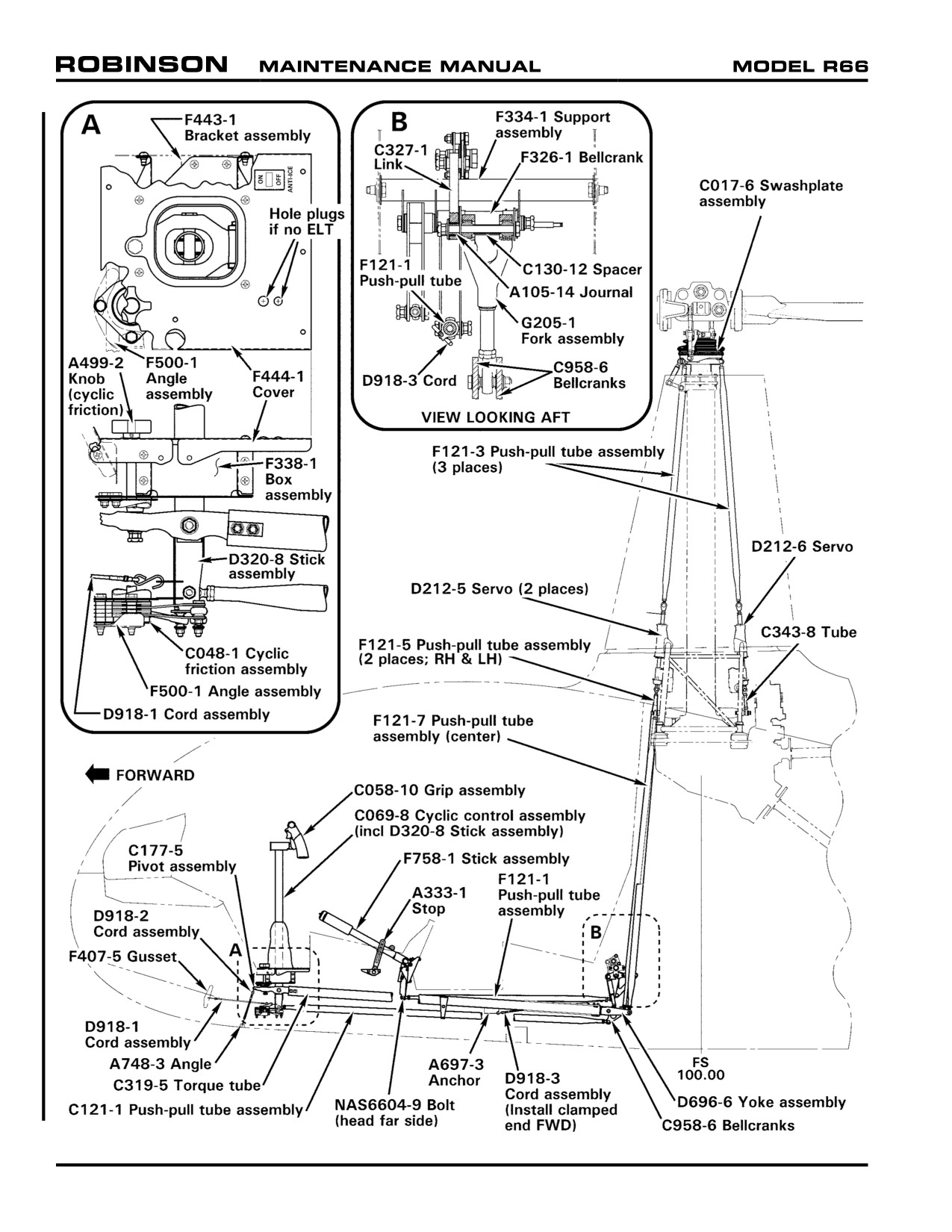
FIGURE 67-1 MAIN ROTOR FLIGHT CONTROLS
Page 67.2
Chapter 67 Flight Controls
MAR 2012
67-11 Cyclic Control Assembly (continued)
A. Removal (continued)
5. Remove hardware securing C121-1 push-pull tube assembly to D320-8 stick
assembly. Remove hardware securing C319-5 torque tube assembly to C177-5
pivot assembly. Move push-pull tube and torque tube assemblies aft, and protect
from scratching.
6. Disconnect, but do not remove, two bolts securing cyclic friction assembly to cabin.
Apply some cyclic friction to keep plates assembled.
7. Remove screws securing F338-1 cyclic box to cabin. Lift and remove cyclic control
assembly with attached cyclic box and friction assembly. Install nuts onto two
cyclic friction assembly bolts, hand tight, to retain bolts and spacers.
8. Remove hardware securing both outboard, vertical F121-5 push-pull tube assemblies
and C130-47 spacer to D696-6 yoke assembly.
9. Remove hardware securing center, vertical F121-7 push-pull tube assemblies to
C958-6 bellcrank.
10. Remove hardware securing G205-1 fork assembly to F334-1 support assembly.
11. Pull D175-5 cyclic pivot assembly (torque tube, yoke, bellcranks, fork, and push-pull
tube assembly) aft through belly.
B.
Installation
1. Refer to Figure 67-1. Verify center-to-center distance between rod end and spherical
bearings in G205-5 fork is 5.40 ± 0.03 inches; adjust as required. Standard torque
jam nut and palnut per Section 20-32. Install C175-5 cyclic pivot assembly (torque
tube, yoke, bellcranks, fork, and push-pull tube assemblies) thru aft belly.
2. Connect G205-1 fork assembly to F326-1 bellcrank and standard torque bolt per
Section 20-32.
3. Connect lower end of center F121-7 push-pull tube to C958-6 bellcranks and standard
torque bolt per Section 20-32.
4. Connect lower ends of both outboard F121-6 push-pull tubes to D696-6 yoke using
a NAS6605-46 bolt and C130-47 spacer and standard torque per Section 20-32.
Install plastic hole plug in vertical keel panel beneath RH, aft seat.
5. Remove temporary nuts from cyclic friction assembly bolts. Position cyclic box
with attached cyclic control and friction assemblies between keel panels. Install all
screws fastening cyclic box to cabin. Fasten cyclic friction assembly to cabin and
standard torque bolts per Section 20-32.
6. Connect C319-5 torque tube assembly to C177-5 pivot and standard torque bolts
per Section 20-32.
7. Connect forward end of C121-1 push-pull tube to D320-8 cyclic stick and standard
torque bolts per Section 20-32.
25 OCT 2010
Chapter 67 Flight Controls
Page 67.3
67-11 Cyclic Control Assembly (continued)
B. Installation (continued)
8. Connect all electrical plugs at bottom of cyclic stick. Ensure protective sleeving
covers maximum amount of wiring possible and sleeving ends are secured with
lacing tape.
9. Connect D918-1 cord to D320-8 cyclic stick. Connect D918-2 cord to C177-5
pivot.
10. Move cyclic control through all positions and verify operating and no binding.
11. Install radio face plate, connect OAT gage and hourmeter wiring connectors, and ty-
rap as required. Close and secure upper console.
12. Connect cyclic box cover anti-ice, pitot heat (if installed), and ELT (if installed) switch
wiring connectors and secure cover.
13. Install cyclic friction knob and secure with spring pin. Close and secure cyclic stick
boot.
14. Install F794-1 (forward) and F794-2 (aft) belly panels, F680-3 (pilot collective) and
F445-1 (forward tunnel) cover assemblies, and F461-1 (collective cross tube) and
F463-1 (aft tunnel) cover assemblies.
67-12 Cyclic Grip Assembly
A. Removal
NOTE
This may be accomplished without removal of complete cyclic
assembly from rotorcraft.
1.
Remove forward belly panel.
2.
Refer to Figure 67-1. Disconnect wiring connectors attached to wiring exiting base
of D320-8 cyclic stick. Using pin extractor, remove pins from housings (wires
112, 138, & 355 may remain installed) and retain housings. Remove lacing tape
from both ends of protective sleeving covering wires exiting base of stick assembly.
Attach a 3 foot length of safety wire or wire lacing tape to one removed pin.
3.
As required, rotate grip assembly by pushing in on spring-loaded stop pin so exposed
wire loom does not wrap around top of D320-8 cyclic stick. Remove circular plug,
D684-1 spring, cotter pin, castellated nut, and washer where grip assembly attaches
to D320-8 cyclic stick.
4.
Remove grommet atop cyclic stick at grip assembly wiring entrance. With a soft-
faced hammer, gently tap cyclic grip assembly pivot and remove grip assembly and
attached wiring from stick assembly. Ensure safety wire or lacing attached to internal
wiring protrudes from top and bottom of stick assembly. Also, ensure pivot bearings
remain with stick assembly.
NOTE
Do not damage bearings while removing.
Page 67.4
Chapter 67 Flight Controls
25 OCT 2010
67-12 Cyclic Grip Assembly (continued)
B.
Installation
1.
Refer to Figure 67-1. Ensure protective sleeving covers wires exiting grip assembly
with one grommet in grip and one (for cyclic stick) on wire bundle (spare grommets
may be installed if desired).
2.
Slide grip assembly into bearings in stick assembly. Install washer, castellated nut
and cotter pin.
CAUTION
Tighten castellated nut only until there is no axial movement of
bearings and cyclic grip assembly. Overtightening nut will dam-
age bearings.
3.
Install D684-1 spring so that when grip assembly is rotated one turn clockwise, with
co-pilot grip removed, pilot grip (tube) will float just above horizontal and stay full-up
when placed full-up. Install circular plug.
4.
Temporarily attach grip assembly wiring to safety wire (or lacing) exiting atop cyclic
stick. Carefully pull wires thru cyclic stick. Install grommet, included with grip
assembly wiring, into cyclic stick wiring entrance hole. Remove safety wire (or
lacing).
5.
Position protective sleeving on wiring exiting cyclic stick bottom to cover maximum
amount of wiring possible. Secure sleeving ends with lacing tape.
6.
Install pins on each wire into proper position in housings. Refer to Figure 98-2 for
pin positions.
7.
Connect cyclic and airframe wiring and ty-rap. Move cyclic control through all
positions and verify clearance and no binding.
8.
Turn BATTERY switch on and verify correct function of all switches on grip assembly
and cyclic stick.
9.
Install forward belly panel.
25 OCT 2010
Chapter 67 Flight Controls
Page 67.5
67-13 Cyclic Friction Assembly
NOTE
The cyclic friction assembly is located below the forward left
corner of the cyclic box. Turning friction knob clockwise applies
friction to both longitudinal and lateral cyclic axes. Adjustment
is required if friction cannot be applied.
A. Friction Adjustment
1. Turn friction knob counter-clockwise until it stops.
2. Remove roll pin connecting knob to shaft.
3. Lift knob off shaft.
4. Install NAS1149F0432P or NAS1149F0463P washers under knob washer, as
required, so knob rotates 1/8 to 1 turn before adding friction. With friction off, force
at grip to move cyclic shall not exceed 1.75 pounds longitudinal and lateral within
hydraulic servo deadbands.
5. Replace knob and install roll pin.
6. Move flight controls throughout complete travel. Verify no binding.
67-20 Collective Control
67-21 Collective Stick Assembly
A. Removal
1. Refer to Figure 67-1. Disconnect A333-1 collective-travel stop from F348-1 anchor
by removing NAS6603 bolt at bottom of stop. Position stop parallel to collective
stick and apply collective friction.
2. Refer to Figure 6-8. Remove F445-1 forward tunnel cover, F680-3 pilot's collective
cover, F680-1 co-pilot's collective cover, F463-1 mid-tunnel cover, and F461-1
collective cross tube cover.
3. Pivot pilot's seat bottom to the open position. Remove bolt securing inboard end of
collective stick to pilot's seat structure. Refer to Figure 76-1. Disconnect throttle
control inner wire from A462-4 fitting at outboard end of collective. Remove three
screws securing C522-10 throttle control to collective cross tube.
4. Disconnect wiring exiting aft end of center collective stick from airframe harness
connector. Remove ty-raps as required.
5. Disconnect forward end of F121-1 push-pull tube from collective stick assembly.
6. Remove bolt securing outboard end of collective stick to F303-1 support. Remove
two remaining screws securing F303-1 support to cabin. Slide support, with attached
micro-switches, down to allow aft movement of collective stick.
7. Pivot pilot's seat bottom to the open position. Remove bolt securing collective stick
assembly to pilot's seat structure.
8. Carefully move collective stick assembly aft and remove from helicopter.
Page 67.6
Chapter 67 Flight Controls
25 OCT 2010
67-21 Collective Stick Assembly (continued)
B.
Installation
1.
Refer to Figure 67-1. Position A333-1 collective-travel stop parallel to collective
stick and apply collective friction. From aft side of co-pilot's seat, carefully position
collective stick assembly in helicopter.
2.
Pivot pilot's seat bottom to the open position. Install bolt from inside pilot's seat
structure thru bearing block into tunnel and secure to inboard end of collective stick
assembly. Standard torque bolt, install palnut, and torque stripe per Figure 5-1.
3.
At outboard end of collective stick, slide F303-1 support, and attached micro-
switches, up behind collective cross tube and secure support to cabin with two
screws.
4.
Install journal in outboard pivot bearing of collective stick assembly. Position journal
& bearing between flanges of F303-1 support and insert NAS6604 bolt. Standard
torque bolt per Section 20-32, install palnut, and torque stripe per Figure 5-1.
5.
Connect forward end of F121-1 push-pull tube to collective stick assembly with
NAS6604 bolt head on outboard (right) side (nut side inboard). Standard torque bolt
per Section 20-32, install palnut, and torque stripe per Figure 5-1.
6.
Refer to Figure 6-8. Slide F680-3 collective cover over center collective stick aft of
friction assembly.
7.
Insert A130-4 spacer into lower end of A333-1 collective-travel stop. Position spacer
and stop in F348-1 anchor. Install NAS1149F0432P and 0463P washers on spacer
on either side of stop as required to obtain 0.001/0.035 inch axial play and align
stop with collective. Secure stop to anchor with NAS6603 bolt, standard torque per
Section 20-32, install palnut, and torque stripe per Figure 5-1. Move collective up &
down and verify no binding of stop.
CAUTION
NAS6604-9 bolt connecting forward end of F121-1 push-pull tube
to collective must be installed so bolt head is toward right side of
helicopter. Refer to Figure 67-1.
8.
Connect wiring exiting center collective stick to airframe wire harness connector.
Secure connector to airframe harness with Ty-raps as required. Move collective up
& down and verify wiring clearance with no strain.
9.
Refer to Figure 76-1. Secure C522-10 throttle control to collective cross tube with
three clamps and screws. Position control inner wire in A462-4 fitting and rig per
Section 76-11.
10.
Refer to Figure 6-8. Install and secure F445-1 forward tunnel cover, F680-3 pilot's
collective cover, F680-1 co-pilot's collective cover, F463-1 mid-tunnel cover, and
F461-1 collective cross tube cover.
11.
Adjust collective friction per Section 67-22.
25 OCT 2010
Chapter 67 Flight Controls
Page 67.7
67-22 Collective Friction
1. Loosen small screw on collective friction lever.
2. Hold friction lever knob fully aft against collective stick. Adjust screw large screw thru
A333-1 stop to produce a force of 18-22 pounds at collective grip within hydraulic
servo deadbands, then tighten small screw on friction lever screw.
67-30 Jackshaft and Strut Assembly
67-31 Jackshaft
A. Removal
NOTE
Rigging check is not necessary if jackshaft support rod end and
push-pull tube lengths are not altered.
1. Disconnect push-pull tubes from F339-1 jackshaft.
2. Disconnect two bolts connecting jackshaft to G201-1 frame.
3. Remove jackshaft.
B.
Installation
1. Ensure A105-6 journal is installed in jackshaft aft support on G201-1 frame. Position
F339-1 jackshaft on G201-1 frame and install bolts. Standard torque bolts per
Section 20-32, install palnuts, and torque stripe per Figure 5-1.
2. Insert bolt forward thru forward jackshaft arm and connect to upper end of F121-7
push-pull tube. Install A115-1 spacer, A214-3 washer and nut. Standard torque
bolt per Section 20-32, install palnut, and torque stripe per Figure 5-1.
3. Insert bolt aft thru aft jackshaft arm and connect to lower rod end on C343-8 tube.
Install A115-1 spacer, A214-3 washer and nut. Standard torque bolt per Section
20-32, install palnut, and torque stripe per Figure 5-1.
4. Verify no binding and/no interference with control system exists throughout flight
control travel.
Page 67.8
Chapter 67 Flight Controls
25 OCT 2010
67-40 Swashplate
A. Removal
NOTE
Rigging check is not required if push-pull tube rod end center-
to-center dimension does not change.
1. Remove main rotor blades and hub per Sections 62-10 and 62-20.
2. Atop of C251 main rotor drive shaft, remove D226 brackets, D151 teeter stops, and
C150 droop stops by removing NAS6608 bolt.
3. Disconnect upper C204 arm from C203 yokes.
4. Disconnect and remove C203 yokes, A210 key, and chord arm weights.
5. Remove swashplate boot by cutting plastic ty-raps.
6. Disconnect three push-pull tubes and A205 fork assembly from lower (non-rotating)
swashplate.
7. Lift swashplate with attached fork and pitch links off slider tube and remove from
helicopter.
B.
Installation
1. Install swashplate onto slider tube assembly. Connect lower scissors’ fork to left side
of middle of three lugs on lower, non-rotating swashplate. Connect aft push-pull tube
to right side of aft, single lug on lower swashplate. Standard torque bolts per Section
20-32. Install palnuts and special torque per Section 20-33.
2. Verify swashplate tilting friction per Section 67-41; adjust as required.
3. Slide swashplate boot over main rotor drive shaft and set in place.
4. Refer to Figures 8-13 and 8-13A. Install C203 yokes on C251 main rotor drive shaft upper
flange using A210 key to index yokes to shaft. Finger tighten clamping hardware.
NOTE
Round edge of A210 key to fit into drive shaft flange indexing slot.
5. Standard torque NAS6605 bolt thru yokes and A210 key first per Section 20-32. Install
palnuts and special torque per Section 20-33.
6. Standard torque bolt thru yokes opposite A210 key per 20-32. A slight gap between
yokes opposite A210 key is normal.
7. Install previously removed chord arm weights and standard torque bolt per Section 20-
32. Install palnut, special torque per Section 20-33, and torque stripe per Figure 5-1.
25 OCT 2010
Chapter 67 Flight Controls
Page 67.9
67-40 Swashplate (continued)
B. Installation (continued)
8.
If required, fill remainder of rod end threaded hole in upper A205 fork with B270-4 or
-13 sealant (see Section 20-70).
9.
With bolt heads in direction of rotation, connect upper A205 fork to upper C204 arm
and connect arm to C203 yokes. Standard torque bolts per Section 20.32. Verify
0.001/0.005 inch axial play in both pivots; adjust C117 shim thickness between nut-
side journal & thrust washer as required. Verify bolt, arm, and clamped hardware in
upper scissor’s pivots rotate together. Install palnuts , special torque per Section 20-
33, and torque stripe per Figure 5-1.
10.
Verify bolt, arm, and clamped hardware in lower scissor’s pivots rotate together.
Connect forward push-pull tube rod ends to remaining lower lugs on swashplate and
standard torque bolts per Section 20-32. Install palnut, special torque per Section 20-
33, and torque stripe per Figure 5-1.
11.
Connect upper A205 fork rod end and lower rod end of C258 pitch link to interrupter-
side swashplate ear and standard torque bolt per Section 20-32. Install palnut, special
torque per Section 20-33, and torque stripe per Figure 5-1.
12.
Position swashplate boot on rotating swashplate with inner lip contacting C203 yoke.
Secure with ty-raps.
13.
Attach two A255-3 counterweights and lower rod end of C258 pitch link to swashplate
ear opposite interrupter and standard torque bolt per Section 20-32. Install palnut,
special torque per Section 20-33, and torque stripe per Figure 5-1.
14.
Install main rotor hub and blades per Sections
62-10 and 62-20.
15.
Verify safety washers (or counterweight) and C115 spacers installed on all rod ends per
Figure 5-1. Torque stripe fasteners per Figure 5-1.
16.
Verify no interference with control movement throughout flight control travel and
swashplate movement corresponds with cyclic and collective movement.
17.
Track and balance main rotor per Section 18-10.
Page 67.10
Chapter 67 Flight Controls
25 OCT 2010
67-41 Swashplate Tilting Friction Adjustment
Swashplate tilting friction is established by C197-1 through C197-6 shims controlling
clamping force of Teflon®-lined sleeves on the ball assembly.
1.
Mark for reassembly and disconnect boot, pitch links and drive linkage (scissors) from
upper swashplate and both forward push-pull tubes from lower swashplate.
2.
Align upper swashplate arms with lateral axis of helicopter and center cyclic stick. Using
MT359-1 spring scale (or equivalent) connected to upper swashplate arm bolt hole,
pull down and note scale reading while swashplate is moving; do not use breakaway
reading. Force required to tilt swashplate must be free-without-looseness minimum to
5 pounds maximum.
3.
To adjust friction, remove outer screws from upper swashplate and raise and secure
retainers to allow access to inner screws on lower, non-rotating swashplate. Remove
inner screws securing sleeve to lower swashplate.
4.
Raise sleeve and measure thickness of C197 shim stack. Adjust shim stack thickness
as required to achieve proper tilting friction. Decreasing shim stack thickness increases
tilting friction while increasing spacer stack thickness decreases tilting friction. Install,
and special torque per Section 20-33, all inner screws on lower swashplate and at least
two screws thru retainers in upper swashplate prior to measuring tilting friction.
5.
Connect both forward push-pull tubes to lower swashplate and standard torque per
Section 20-32. Install palnut, special torque per Section 20-33, and torque stripe per
Figure 5-1.
6.
Connect both pitch links and drive linkage to upper swashplate (interrupter on same side
as drive linkage) and standard torque per Section 20-32. Install palnuts, special torque
per Section 20-33, and torque stripe per Figure 5-1.
67-42 Upper and Lower Scissor Assemblies
A. Bearing Removal
C648-2 journal bearings may be removed with a press. Press from inner side of bearings
while supporting outboard side of yoke or fork. Use a socket or other suitable pressing
tool to apply the force.
B. Bearing Installation
1. Clean mating surfaces of A205 fork or C203 yoke where C648 bearing is installed.
Deburr any sharp edges that may damage bearings during installation.
2. Coat yoke or fork bearing bores with zinc chromate or epoxy primer. While primer
is still wet, press in C648-2 bearing while supporting backside of fork or yoke.
MAR 2012
Chapter 67 Flight Controls
Page 67.11
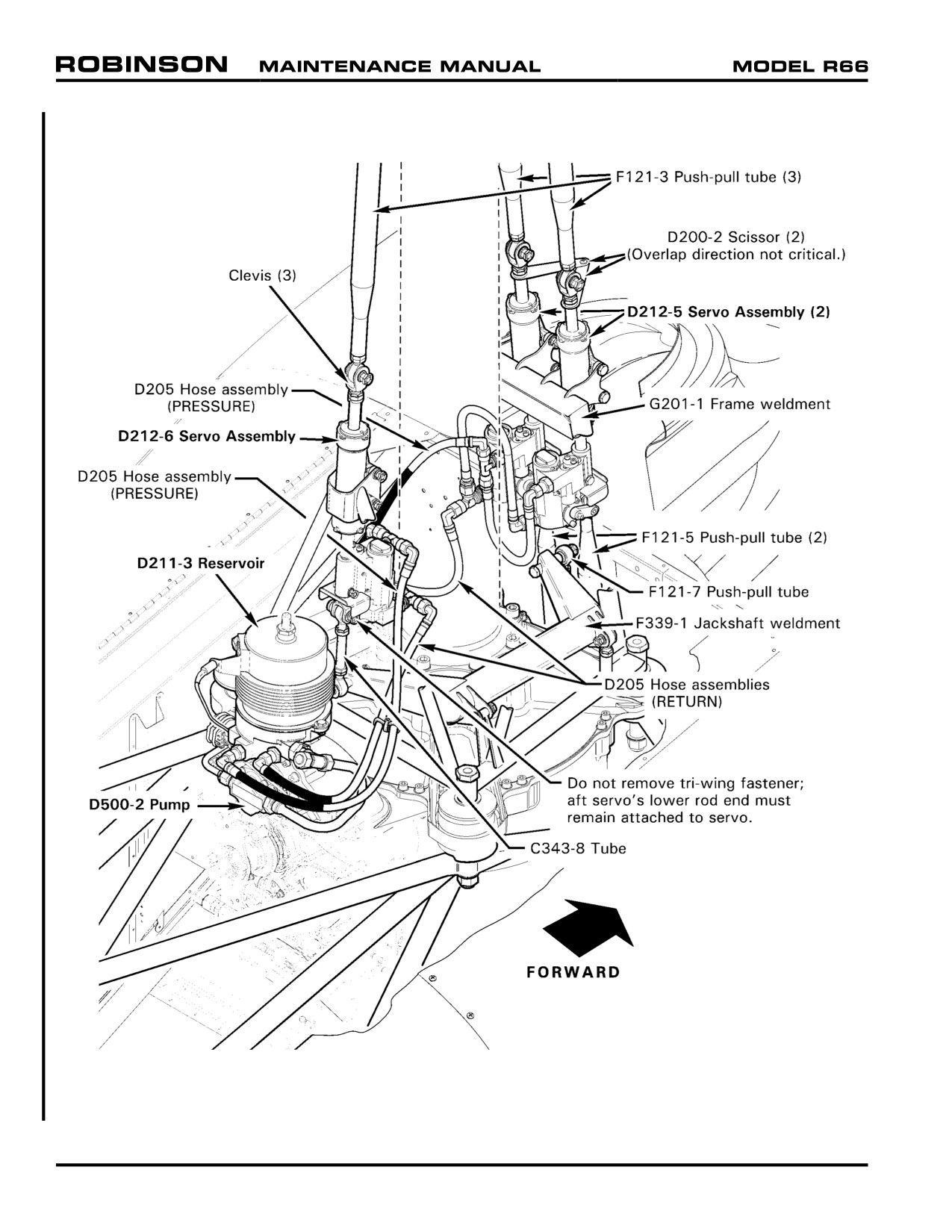
FIGURE 67-2 HYDRAULIC FLIGHT CONTROL SYSTEM
Page 67.12
Chapter 67 Flight Controls
MAR 2012
67-50 Hydraulic System
WARNING
Except as instructed in this manual, service on the hydraulic
system is limited to component removal and replacement.
CAUTION
Cleanliness of hydraulic fluid is vital to proper system
operation. Use only clean fluid from sealed containers and
avoid contamination from dirty funnels, tubing, etc. Use LPS
PreSolve to clean hydraulic parts. Do not use alcohol.
Hydraulically boosted main rotor flight controls eliminate cyclic and collective feedback forces.
The hydraulic system consists of a pump, three servos, a reservoir, and interconnecting lines.
Normal operating pressure is 450 to 500 psi. The pump is mounted on and driven by the main
rotor gearbox. A servo is connected to each of the three push-pull tubes that support the
main rotor swashplate. The reservoir is mounted to the aft end of the main rotor gearbox and
includes a filter, pressure relief valve, and pilot-controlled pressure shut-off valve.
A sight glass for pre-flight fluid level checks is incorporated in the reservoir and accessible via a
left side cowl door. A vented filler cap is located on top of the reservoir.
The pressure shut-off valve is solenoid-actuated and controlled by the hydraulic switch on the
pilot's cyclic. The switch should be left on during helicopter shutdown and start up except during
the hydraulic system check.
Electrical power is required to turn off hydraulics. Pulling HYD circuit breaker will NOT turn off
hydraulics but will disable hydraulic switch.
67-51 Hydraulic Pump
A. Removal
1. Remove tailcone cowling per Section 53-23.
2. Remove hydraulic reservoir filler-vent and temporarily install an air-tight plug.
3. Refer to Figure 12-4. Remove F902 suction line assembly and protect exposed line
and fitting openings.
4. Remove F902 pressure line assembly and protect exposed line and fitting openings.
5. Remove aft jam nut from both MR rpm senders and remove both senders from
bracket attached to hydraulic pump. Temporarily secure senders away from drive
train to prevent damage.
6. Remove four self-locking nuts and washers securing pump to gearbox and remove
pump and o-ring. Discard o-ring. Protect pump opening on gearbox.
MAR 2012
Chapter 67 Flight Controls
Page 67.13
67-51 Hydraulic Pump (continued)
B. Installation
1. Prelubricate new o-ring with gearbox oil and install on pump mounting flange. With
pump bracket pointing down, install pump on gearbox and secure. Special torque
nuts per Section 20-33.
2. Install both MR rpm senders in pump bracket. Adjust clearance between both senders
and both yoke magnets to 0.040/0.020 inch and hand-tighten sender jam nuts.
3. Refer to Figure 12-4. Install F902 pressure line assembly and special torque per
Section 20-33.
4. Install F902 suction line assembly and special torque per Section 20-33.
5. Remove temporary air-tight plug from reservoir and adjust fluid level as required.
Install filler-vent and special torque per Section 20-33.
6. Torque stripe jam nuts and B-nuts.
7. Bleed hydraulic system per Section 12-34.
8. Install a 110-4 Telatemp on aft surface of pump.
9. Install tailcone cowling per Section 53-23.
67-52 Hydraulic Reservoir
A. Removal
1. Temporarily install a "DO NOT MOVE FLIGHT CONTROLS" sign in cockpit.
2. Remove tailcone cowling per Section 53-23.
3. Place a one-liter container beneath suction tee fitting on reservoir. Remove cap from
tee fitting and allow reservoir fluid to drain into container. Reinstall cap and special
torque per Section 20-33.
4. Remove suction and pressure lines, and disconnect & cap servo supply & return
hoses, from reservoir. Protect line and fitting openings.
5. Disconnect pump bypass solenoid and sight gage LED electrical connectors.
6. Remove three screws securing reservoir to gearbox and remove reservoir.
7. Note alignment of tee fittings and sight gage LED. Transfer LED and line and hose
fittings from removed reservoir to replacement reservoir.
Page 67.14
Chapter 67 Flight Controls
MAR 2012
67-52 Hydraulic Reservoir (continued)
B. Installation
1. Note alignment of tee fittings and sight gage LED on removed reservoir. Transfer
LED and line and hose fittings from removed reservoir to replacement reservoir.
Special torque fittings per Section 20-33.
2. Install reservoir on gearbox and secure with three screws.
3. Install pressure and suction lines, repositioning tee fittings as required, and special
torque per Section 20-33.
4. Connect servo supply and return hoses to reservoir. Position hose elbows to minimize
preload and special torque per Section 20-33.
5. Connect pump bypass solenoid and sight gage LED electrical connectors and ty-rap
wires as required.
6. Fill reservoir with A257-15 hydraulic fluid and special torque filler vent per Section
20-33.
7. Bleed hydraulic system per Section 12-34.
8. Install tailcone cowling per Section 53-23.
MAR 2012
Chapter 67 Flight Controls
Page 67.15
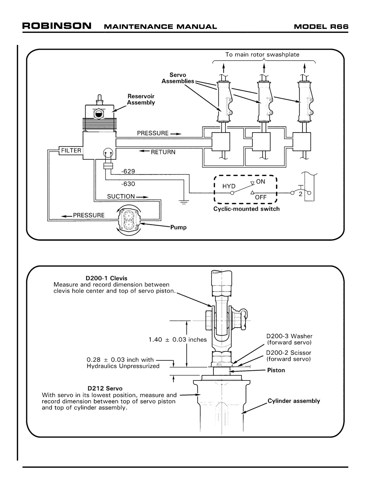
FIGURE 67-3A HYDRAULIC SYSTEM SCHEMATIC
FIGURE 67-3B HYDRAULIC SERVO RIGGING
Page 67.15A
Chapter 67 Flight Controls
MAR 2012
67-53 Hydraulic Servos
A. Servo Removal
CAUTION
Do not pressurize hydraulic system while any hydraulic system
component is disconnected or removed.
1.
Remove mast fairing per Section 53-22. Remove tailcone cowling per Section 53-23.
2.
Refer to Figures 67-2 and 67-3B. Perform the following measurements on all D212
hydraulic servo assemblies to be removed:
a. Measure & record dimension between D200-1 clevis hole center & top of servo
piston.
b. Apply cyclic and collective frictions. With collective full down and hydraulics
unpressurized, position cyclic stick so piston in servo to be removed is in its
lowest position. Measure & record dimension between top of servo piston and
top of cylinder assembly.
3.
Remove hardware securing servo clevis to F121-3 push-pull tube’s lower rod end.
4.
a. Forward Servo: Remove hardware securing servo to F121-5 push-pull tube’s
upper rod end. Remove hardware joining D200-2 scissors.
b. Aft Servo: Remove hardware securing C343-8 tube’s lower rod end to F339-1
jackshaft weldment.
5.
Disconnect D205 hose assemblies from servo unions and tees. Cap and plug fittings.
6.
Remove hardware securing servo to G201-1 frame weldment and remove servo.
7.
Aft Servo: Measure & record center-to-center dimension between aft servo’s lower
rod end and C343-8 tube’s lower rod end. Loosen palnut and nut securing C343-8
tube to aft servo’s lower rod end and remove tube.
CAUTION
Do not remove tri-wing fastener; aft servo’s lower rod end must
remain attached to servo.
CAUTION
Dimension between clevis hole center and top of servo piston
must be 1.40 ± 0.03 inches; dimension between top of servo
piston and top of cylinder assembly must be 0.28 ± 0.03 inch;
dimension between C343-8 tube’s rod ends must be 4.00 ± 0.03
inches. If dimension(s) are not within required range, perform
main rotor rigging per Section 18-40 after servo installation.
8.
Remove clevis, scissor, D200-3 washer, unions, and tee fittings from servo, as
applicable.
9.
Actuate servo piston by hand and drain as much hydraulic fluid from servo as possible.
Plug servo ports.
MAR 2012
Chapter 67 Flight Controls
Page 67.15B
67-53 Hydraulic Servos (continued)
B.
Servo Installation
CAUTION
Do not pressurize hydraulic system while any hydraulic system
component is disconnected or removed.
CAUTION
Refer to Part A. Dimension between clevis hole center and top
of servo piston must be 1.40 ± 0.03 inches; dimension between
top of servo piston and top of cylinder assembly must be 0.28
± 0.03 inch; dimension between C343-8 tube’s rod ends must
be 4.00 ± 0.03 inches. If dimension(s) recorded during servo
removal were not within required range, or if dimension(s) are
unknown, adjust to correct dimensions in Part B steps 1 and 2,
proceed with servo installation thru step 10, then perform main
rotor rigging per Section 18-40.
1.
Refer to Figures 67-2 and 67-3B. Lightly coat D200-1 clevis threads with B270-21
protectant. Assemble clevis, palnut, nut, D200-3 washer (forward servo), and D200-2
scissor (forward servo), and install assembly in D212 hydraulic servo assembly piston.
Adjust dimension between clevis hole center & top of servo piston to dimension
recorded during servo removal, then tighten jam nut and palnut finger tight.
2.
Aft Servo: Lightly coat servo’s lower rod end threads with B270-21 protectant and
install C343-8 tube. Adjust tube on servo‘s rod end, and tube’s rod end, to the
center-to-center dimension (between rod ends) recorded during servo removal, and
with rod ends 90° to each other. Tighten jam nuts and palnuts finger tight.
CAUTION
Do not remove tri-wing fastener; aft servo’s lower rod end must
remain attached to servo.
3.
Install hardware securing servo to G201-1 frame weldment. Standard torque
fasteners per Section 20-32 and torque stripe per Figure 5-1.
4.
Forward Servos: Install hardware joining scissors (scissor overlap direction not
critical); special torque nut to 25 in.-lb, special torque palnut to 5-10 in.-lb, and
torque stripe per Figure 5-1.
5.
Using backup wrench, align clevis parallel with helicopter’s longitudinal axis, standard
torque jam nut and palnut per Section 20-32, and torque stripe per Figure 5-1.
6.
Install hardware securing servo clevis to F121-3 push-pull tube’s lower rod end.
Standard torque fastener per Section 20-32 and torque stripe per Figure 5-1.
7.
a. Forward Servo: Install hardware securing servo to F121-5 push-pull tube’s upper rod
end. Standard torque fastener per Section 20-32 and torque stripe per Figure 5-1.
b. Aft Servo: Install hardware securing C343-8 tube’s lower rod end to F339-1
jackshaft weldment. Standard torque fastener per Section 20-32 and torque stripe
per Figure 5-1. Using backup wrench, standard torque jam nuts and palnuts, and
torque stripe per Figure 5-1.
Page 67.16
Chapter 67 Flight Controls
MAR 2012
67-53 Hydraulic Servos (continued)
B. Servo Installation (continued)
8.
Refer to Figure 5-2. Verify proper rod end centering on all push-pull tubes attached
to servos.
9.
Remove caps and plugs. Lubricate new packings using A257-15 hydraulic fluid and
install packings on servo unions and tees. Install fittings with associated hardware in
servo ports and connect D205 hose assemblies to fittings. Align fittings to minimize
hose preload and ensure hose clearance with surrounding structure; special torque
fittings per Section 20-33 and torque stripe per Figure 5-1. Special torque hose
B-nuts per Section 20-33 and torque stripe per Figure 5-1.
10.
Bleed hydraulic system per Section 12-34.
11.
Perform the following measurements on all servos just installed:
a. Measure & record dimension between clevis hole center & top of servo piston.
b. Apply cyclic and collective frictions. With collective full down and hydraulics
unpressurized, position cyclic stick so piston in servo just installed is in its lowest
position. Measure & record dimension between top of servo piston and top of
cylinder assembly.
CAUTION
Dimension between clevis hole center and top of servo piston
must be 1.40 ± 0.03 inches; dimension between top of servo
piston and top of cylinder assembly must be 0.28 ± 0.03 inch;
dimension between C343-8 tube’s rod ends must be 4.00 ±
0.03 inches. If dimension(s) recorded are not within required
range, adjust to correct dimensions in Part B steps 1 and 2,
proceed with servo installation thru step 10, then perform main
rotor rigging per Section 18-40.
12.
Install tailcone cowling per Section 53-23. Install mast fairing per Section 53-22.
MAR 2012
Chapter 67 Flight Controls
Page 67.17
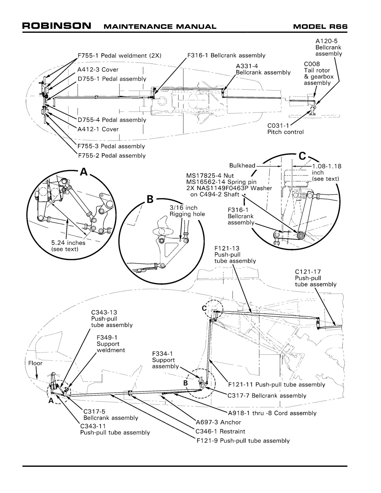
FIGURE 67-4 TAIL ROTOR FLIGHT CONTROLS
Page 67.18
Chapter 67 Flight Controls
MAR 2012
67-60 Tail Rotor Controls
67-61 Pedals
A. Removal
1.
Soak both front floor carpets with Prep-sol for 15-20 minutes, then lift carpet
carefully from the floor on both sides and remove from the cabin. Caution: This is a
flammable material. Follow manufacturer’s safety precautions to prevent injury.
2.
Refer to Figure 67-4. Remove the screws between the pedals holding the access
plates to the floor and remove the plates.
3.
Remove screws securing upper console and pivot console up and aft.
4.
Disconnect both pedal assemblies from the C343-9 & -11 push-pull tubes.
CAUTION
DO NOT remove the rod ends or change the length of the push-
pull tubes.
5.
Remove six NAS6603-20 bolts (three per side) which hold the A318-1 and -2 bearing
block halves together.
6.
Remove the lower bearing block halves.
7.
Remove the tail rotor pedals one at a time by lifting one end and lowering other into
chin. Remove pedals thru pilot-side opening.
NOTE
On reassembly, the right pedal assembly is mounted forward in
the bearing blocks and the left is mounted aft.
NOTE
Pedal blocks (upper and lower) are a machined matched set as
indicated by matching letter or number on the upper and lower
portion of blocks. DO NOT mix them or alignment problems
may develop on installation.
25 OCT 2010
Chapter 67 Flight Controls
Page 67.19
67-61 Pedals (continued)
B. Installation
1. Fill the grooves in the pedal bearing blocks with A257-1 grease.
2. Install the pedal assemblies into the bearing blocks and torque the bearing block
attach bolts per Section 20-32.
NOTE
If a force greater than 5 lbs is required to move pedals, check
the bearing blocks to ensure they are matched correctly.
3. Connect both pedal assemblies to the push-pull tubes and torque the NAS6604-9
bolts to per Section 20-32 and install palnuts.
4. Move the pedals through the full range of travel to ensure there is no interference or
binding.
5. Secure console. Install the pedal cover plates and carpeting. Use B270-7 or -8
adhesive to attach carpeting.
67-62 Pitch Control
A. Removal
1. Remove tail rotor assembly per Section 64-11. Mark corresponding tail rotor blade
grips, tail rotor pitch change to each of the pitch control ears, for later reinstallation
so re-rigging is not required.
2. Disconnect and remove A120-5 aft bellcrank per Section 67-75.
3. Remove C031-1 pitch control from tail rotor output shaft. Clean output shaft.
B.
Installation
1. Verify inner bore of C031-1 pitch control is clean. Slide pitch control assembly onto
clean output shaft.
2. With pitch control's input stud thru short arm of A120-5 bellcrank assembly, position
bellcrank on tail rotor gearbox and install NAS6604-25 bolt, one AN960-416L
washer under bolt head, two MS20002-4 washers, one on each side of bearing and
MS21042-L4 nut. Tighten but don’t torque at this time.
3. Measure vertical gap between A120-5 bellcrank arm and flange on pitch control
stud. Install sufficient C117-34, - 35 and -36 washers between bellcrank and stud to
fill gap within ± 0.003 inch. Install one NAS1149F0432P washer and MS21042-L5
nut on protruding end of stud. Torque nut to 200 in.-lb plus nut drag while holding
stud from rotating. Install palnut and special torque per Section 20-33.
4. Standard torque bolt thru A120-5 bellcrank pivot per Section 20-32 and install palnut
and special torque per Section 20-33.
5. Attach aft end of C121-17 push-pull tube to A120-5 bellcrank and standard torque
bolt per Section 20-32.
6. Install hardware securing pitch links, standard torque bolts and palnuts per Section
20-32, and torque stripe per Figure 5-1.
7. Install tail rotor assembly per Section 64-10.
Page 67.20
Chapter 67 Flight Controls
25 OCT 2010
67-70 Bellcranks
67-71 C317-5 Bellcrank
A. Removal
1. Remove two screws securing the upper console. Lift up console and disconnect
outside air temperature gage wiring.
2. Remove radios, radio panel face plate, and radio rack which is secured with screws
to the side panels.
3. Refer to Figure 67-4. Disconnect forward C343-11 and C343-13 push-pull tubes
and push-pull tube from the bellcrank by removing three NAS6604-9 bolts.
4. Remove four screws securing F349-1 support weldment to cabin and remove support
and attached bellcrank.
5. Remove NAS6604-19 bolt which connects the bellcrank to the support. Remove
bellcrank.
B.
Installation
This procedure also covers rigging of the lower push-pull tubes and pedal assemblies.
Rigging is required if any push-pull tube length changed. If rigging is not required,
disregard rigging portions and follow installation sequences.
1. Install two A105-3 journals inside C317-5 bellcrank. Place one A141-3 washer
both outboard faces of A105-3 journals and secure to F349-1 support weldment.
Standard torque bolt per Section 20-32. Install palnut and special torque per Section
20-33.
2. Install support assembly in helicopter and secure with four MS27039C0807
screws.
3. C343-11 push-pull tube's rod end center-to-center dimension to 6.00 inches and
connect it to the C317-5 bellcrank.
4. Adjust C343-13 push-pull tube's rod end center-to-center dimension to 5.30 inches
and connect it to the C317-5 bellcrank.
5. Ensure F121-9 push-pull tube is installed through the center of the C346-1 restraint
at the mid span position. Connect forward end of F121-9 push-pull tube to C317-5
bellcrank.
6. Install a 3/16-inch diameter pin through the rigging hole located in the right aft
passenger cargo compartment and push it through C317-7 bellcrank's rigging hole.
With rigging pin installed, adjust length of F121-9 push-pull tube to achieve 5.24
inches dimension shown in Figure 67-4. Verify proper rod end thread engagement.
Remove rigging pin and standard torque bolt per Section 20-32. Install palnut,
special torque per Section 20-33, and torque stripe per Figure 5-1.
7. Move pedals full travel. Verify easy, smooth movement with no interference between
tubes, wires and structure.
8. Install radio rack, radio face plate, and radios. Connect outside air temperature gage
wiring.
9. Close and secure upper console.
25 OCT 2010
Chapter 67 Flight Controls
Page 67.21
67-72 C317-7 Bellcrank
A. Removal
1. Refer to Section 6-70. Remove F794-2 aft belly cover, F932-1 middle seat backrest
assembly, and F474-2 middle seat cover.
2. Disconnect F121-9 and F121-11 push-pull tubes from the C317-7 bellcrank.
3. Remove nuts and accompanying washers securing NAS6604-67 bolt in F334-1
support assembly. Withdraw bolt sufficient to remove C317-7 bellcrank and remove
bellcrank, two A141-3 washers, and two A105-3 journals.
B.
Installation
1. Install two A105-3 journals in C317-7 bellcrank's pivot bearing bore. With 3/16 inch
rigging pin hole aft and an A141-3 washer against outboard face of each journal,
install bellcrank on F334-1 support assembly and retain with NAS6604-67 bolt.
2. Install two NAS1149F0463P and one NAS1149F0432P washer followed by
MS21042L4 nut on NAS6604-67 bolt. Standard torque bolt per Section 20-32.
Install palnut, special torque per Section 20-33, and torque stripe per Figure 5-1.
3. Connect F121-9 push-pull tube assembly to C317-7 bellcrank and standard torque
bolt per Section 20-32. Install palnut, special torque per Section 30-33, and torque
stripe per Figure 5-1.
4. Move pedals full travel. Verify smooth movement and no interference.
5. Install F794-2 aft belly cover, F932-1 middle seat backrest assembly, and F474-2
middle seat cover.
67-73 F316-1 Bellcrank
A. Removal
1. Remove main rotor gearbox per Section 63-20.
2. Disconnect F121-11 push-pull tube from F316-1 bellcrank assembly.
3. Disconnect F121-13 push-pull tube from F316-1 bellcrank assembly.
4. Remove nuts and spacer from outboard end of C494-2 shaft. Move shaft slightly
inboard and remove washer from between frame tab and bellcrank.
5. Remove spring pin, castellated nut, and washers from inboard end of C494-2 shaft.
Move shaft slightly outboard and remove washer from between bellcrank and inboard
support.
6. Remove bellcrank.
Page 67.22
Chapter 67 Flight Controls
25 OCT 2010
67-73 F316-1 Bellcrank (continued)
B.
Installation
1. Install one A141-3 washer on C494-2 shaft adjacent to both inboard and outboard
end of F316-1 bellcrank.
2. Install bellcrank with washers in helicopter with longer arm pointing up.
3. On inboard end of C494-2 shaft, install two NAS1149F0463P washers followed by
MS17825-4 castellated nut. Tighten nut until it aligns with hole in shaft and install
new MS16562-14 spring pin.
4. On outboard end of shaft install C130-34 spacer and MS21042L4 nut. Special
torque nut to 90 in.-lb. Install palnut and special torque per Section 20-33. Torque
stripe inboard and outboard nuts per Figure 5-1.
5. Connect F121-13 push-pull tube to bellcrank and standard torque bolt per Section
20-32. Install palnut, special torque per Section 20-33, and torque stripe per Figure
5-1.
6. Connect F121-11 push-pull tube to bellcrank and standard torque bolt per Section
20-32. Install palnut, special torque per Section 20-33, and torque stripe per Figure
5-1.
7. Move pedal full travel. Verify smooth movement and no interference.
8. Install main rotor gearbox per Section 63-20.
67-74 A331-4 Bellcrank
A. Removal
1. Disconnect F121-13 and C121-17 push-pull tubes from A331-4 bellcrank.
2. Disconnect NAS6604-35 attach bolt and remove bellcrank and two A105-3
journals.
B. Installation
1. Install two A105-3 journals in C331-4 bellcrank's pivot bearings. Install an
NAS1149F0432P washer under head of an NAS6604-35 bolt followed by an A141-
3 washer and insert bolt thru journals. Install an A141-3 washer on bolt against
journal face, followed by an NAS1149F0432P washer.
2. Install bellcrank, with straight side aft, on F020-1 frame's boss, and secure to frame
with an NAS1149F0432P washer and MS21042L4 nut. Standard torque bolt per
Section 20-32. Install palnut, special torque per Section 20-33, and torque stripe
per Figure 5-1.
25 OCT 2010
Chapter 67 Flight Controls
Page 67.23
67-75 A120-5 Bellcrank
A. Removal
1. Disconnect C121-17 push-pull tube from A120-5 aft bellcrank.
2. Disconnect bellcrank pivot from C021-1 tail rotor gearbox.
3. Remove nut holding bellcrank to the pitch control. Remove bellcrank and reinstall
nut, and shims found between bellcrank and pitch control.
B. Installation
1. Install pitch control per Section 67-62.
Page 67.24
Chapter 67 Flight Controls
25 OCT 2010
CHAPTER 71
POWERPLANT
Section
Title
Page
71-00
Description
71.1
71-10
Engine
71.3
71-11
Preparing Engine for Rolls-Royce Maintenance Facility . .
71.6
71-12
Preparing Engine for Helicopter Installation
71.7
71-20
Induction
71.11
71-21
Air Filter Assembly
71.11
71-22
Cage Assembly
71.12
71-23
Engine Inlet Bellmouth
71.12
71-30
Exhaust Weldment
71.15
71-40
Accessories
71.16
71-41
Starter-Generator
71.16
71-42
Generator Control Unit (GCU)
71.16
71-43
Engine Monitoring Unit (EMU)
71.17
Chapter 71 Powerplant
Page 71.i
Intentionally Blank
Page 71.ii
Chapter 71 Powerplant
CHAPTER 71
POWERPLANT
71-00 Description
One Rolls-Royce model 250-C300/A1 (commercial designation RR300) free-turbine turboshaft
engine powers the helicopter. The engine is equipped with an ignition exciter, igniter, starter-
generator, two tachometer senders, and additional powerplant instrument senders.
A direct drive, squirrel cage style cooling fan is mounted to the intermediate shaft and supplies
cooling air to the engine and gearbox oil coolers.
Induction air enters through multiple openings in the upper fuselage cowlings and flows into
a plenum forward of the firewall. The plenum contains a radial-flow air filter at the engine
compressor inlet.
If the air filter becomes blocked, spring-loaded doors at the front of the filter housing open
allowing unfiltered air to the engine. The AIR FILTER annunciator illuminates when filter
bypass is occurring.
Periodically performing power assurance checks may provide indication of engine deterioration
or air filter blockage. Maintenance actions such as air filter cleaning and compressor wash
should be performed if aircraft fails power assurance check.
A temperature switch is mounted to the firewall above the engine to detect a fire in the
engine compartment. Abnormally high temperature causes the ENGINE FIRE annunciator to
illuminate.
Chapter 71 Powerplant
Page 71.1
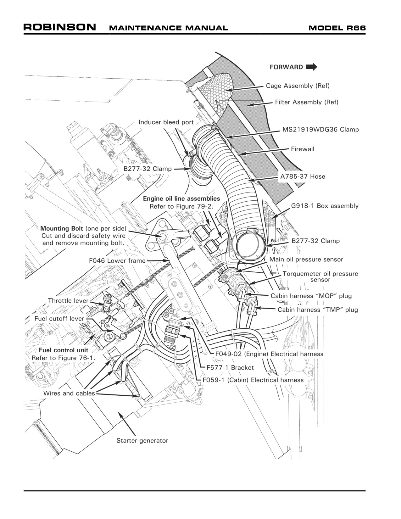
FIGURE 71-1 ENGINE - RIGHT SIDE
Page 71.2
Chapter 71 Powerplant
71-10 Engine
Refer to R66 Illustrated Parts Catalog (IPC) Chapter 71.
NOTE
The electronic monitoring unit (EMU) is a serialized component
assigned to the engine. When removing the engine, remove the
engine's EMU per Section 71-43, as required.
A. Removal
1.
Remove engine cowling assembly per Section 53-21.
2.
Refer to Figures 71-1 and 71-2. Verify heat shrink stamping is legible (or mark wires
and cables) and remove hardware securing wires and cables to starter-generator studs.
Disconnect F059-01 (cabin) electrical harness from F049-02 (engine) harness at F577-1
bracket assembly. Disconnect cabin harness "TMP" (torquemeter oil pressure) and
"MOP" (main oil pressure) plugs from engine sensors; disconnect cabin harness plug
from N2 speed sensor.
3.
Pull fuel shut off valve OFF. Disconnect B283-12 (fuel) hose assembly B-nut from
engine fuel inlet fitting. Cap fitting and plug line.
4.
Remove hardware securing MS21919WDG36 clamp to firewall, and loosen B277-
32 clamps securing A785-37 hose to inducer bleed port and G918-1 box assembly.
Remove hose and clamps. Install cover on inducer bleed port and tape box assembly to
protect openings from contaminants.
5.
Remove hardware securing G391-1 (customer air) line assembly clamps. Loosen line
assembly B-nut from G391-5 line assembly union and disconnect B-nut from engine
compressor union. Cap fitting and plug line.
6.
Drain engine oil per Section 12-60; drain engine oil per RR300 Operation and Maintenance
Manual (OMM). Refer to Figure 79-2. Remove hardware securing F723 oil line assembly
clamps. Loosen F723-1, F723-2, and F723-3 line assembly B-nuts from F649-1 oil cooler
and G689-1 oil tank assembly unions; disconnect B-nuts from engine fittings. Cap fittings
and plug lines.
7.
Refer to Figure 63-1. Remove hardware securing F018-1 clutch assembly yoke to (aft)
A947-2 plate assembly, noting hardware removed.
8.
Refer to Figure 76-1. Remove fasteners securing C522-10 (throttle) and A522-10 (fuel
cutoff) control inner wires to FCU throttle and fuel cutoff levers. Remove fasteners securing
control housings and AN742-4 clamps to F577 bracket assemblies. Refer to Figure 76-2.
Remove cotter pin and washer securing C522-11 (power turbine governor) control inner
sleeve and D333-13 fitting to PTG input lever; disconnect control from lever.
9.
Remove exhaust per Section 71-30.
10.
Connect engine hoist to G200-1 engine lifting lug. Support engine during mounting
hardware removal.
11.
Cut and discard safety wire and remove two bolts securing bottom engine mount to
F174-1 support weldment. Cut and discard safety wire and remove two bolts (one per
side) securing side engine mounts to F046 lower frames.
12.
Carefully remove engine; verify F579-1 bellmouth is clear of firewall, and loose wires, cables,
fittings and line assemblies are clear of engine during separation. Install bellmouth cover.
13.
Prepare engine for Rolls-Royce maintenance facility per Section 71-11, as required.
Chapter 71 Powerplant
Page 71.3
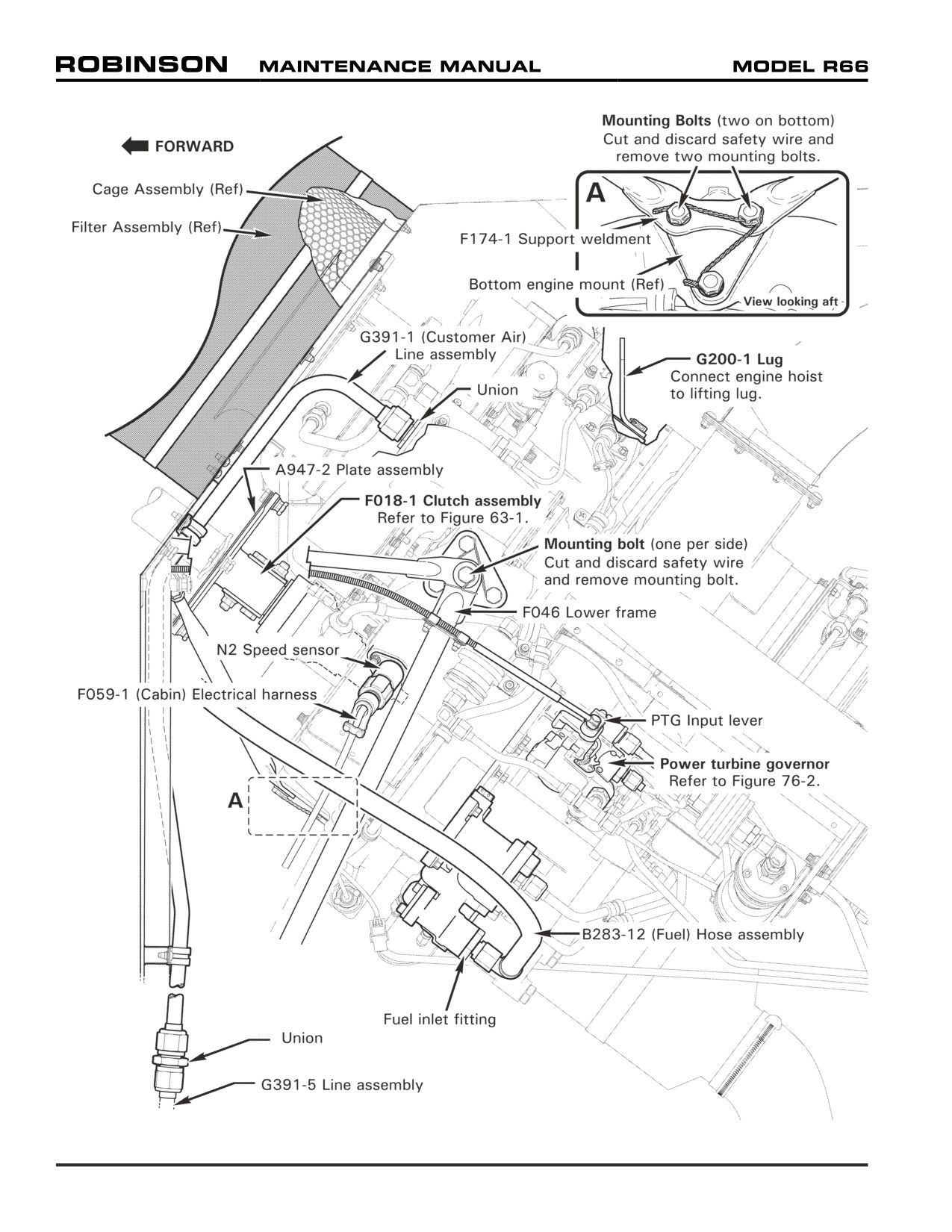
FIGURE 71-2 ENGINE - LEFT SIDE
Page 71.4
Chapter 71 Powerplant
71-10 Engine (continued)
B.
Installation
1.
Prepare engine for installation in helicopter per Section 71-12, as required.
2.
Refer to Figures 71-1 and 71-2. Connect engine hoist to G200-1 engine lifting lug.
3.
Remove F579-1 bellmouth cover. Carefully install engine, inserting bellmouth through
firewall. Do not pinch loose wires or cables, or damage fittings or line assemblies. Before
installing engine mounting hardware, verify the inlet seal is centered when pressed
against the firewall, and that the seal is not twisted or pinched.
4.
Install hardware securing side engine mounts to F046 frames. Standard torque bolts
(one per side) per Section 20-32; install 0.032-inch diameter lockwire and safety bolts
to frames. Install hardware securing bottom engine mount to F714-1 support weldment.
Special torque bolts per Section 20-33; install 0.032-inch diameter lockwire and safety
three bolts together. Remove engine hoist.
5.
Install exhaust per Section 71-30.
6.
Refer to Figure 63-1. Install hardware securing F018-1 clutch assembly yoke to (aft)
A947-2 plate assembly, as removed. Perform engine driveline shimming per Section
63-11. Standard torque nuts and palnuts per Section 20-32, and torque stripe per
Figure 5-1. Verify 0.2 inch minimum clearance between shaft weldment and firewall
grommet; verify equal gap concentrically between shaft and box assembly hole edges.
Adjust F174-1 support weldment rod ends per Section 53-31 as required.
7.
Remove cap and torque check engine compressor (customer air) union per RR300
Operation and Maintenance Manual (OMM). Remove plug and connect G391-1 line
assembly B-nut to engine. Special torque B-nuts per Section 20-33 and torque stripe
fittings. Install hardware securing line assembly clamps.
8.
Refer to Figure 79-2. Remove caps and torque check engine (oil line) fittings per RR300
OMM. Remove plugs and connect F723-1, F723-2, and F723-3 line assembly B-nuts to
engine. Special torque B-nuts at engine, F649-1 oil cooler, and G689-1 oil tank assembly
per Section 20-33, and torque stripe fittings. Install hardware securing line assembly
clamps. Service engine oil per RR300 OMM; service engine oil per Section 12-60.
9.
Remove cover and tape and install B277-32 clamps and A785-37 hose onto inducer
bleed port and G918-1 box assembly; tighten clamps. Install MS21919WDG36 clamp
around hose, and install hardware securing clamp and hose to firewall. Verify security.
10.
Remove cap and torque check engine fuel inlet fitting per RR300 OMM. Remove plug
and connect B283-12 (fuel) hose assembly B-nut to inlet fitting. Special torque B-nut
per Section 20-33 and torque stripe per Figure 5-1. Push fuel shut off valve ON.
11.
Connect F059-01 (cabin) electrical harness plug to N2 speed sensor; connect cabin
harness "TMP" (torquemeter oil pressure) and "MOP" (main oil pressure) plugs to
engine sensors. Connect cabin harness to F049-02 (engine) harness at F577-1 bracket
assembly. Install wires and cables on starter-generator studs according to stamping.
Install hardware, special torque nuts, and torque stripe per Figure 5-1.
12.
Perform FCU throttle and fuel cutoff control rigging per Sections 76-11 and 76-12. Perform
PTG control rigging per Section 76-21 (perform PTG rigging check during run-up).
13.
Install engine EMU per Section 71-60, as required.
14.
Perform ground check per Section 5-41. Remove the air from the engine fuel system,
then perform fuel flow check, per RR300 OMM. Perform run-up per Section 5-42, and
PTG rigging check per Section 76-22.
15.
Install engine cowling assembly per Section 53-21.
Chapter 71 Powerplant
Page 71.5
71-11 Preparing Engine for Rolls-Royce Maintenance Facility
Refer to R66 Illustrated Parts Catalog (IPC) Chapter 71.
NOTE
Cap and plug Rolls-Royce engine model 250-C300/A1 engine
fluid ports, electrical connectors, etc., and in removed
components, progressively during procedure to prevent foreign
object contamination.
1.
Refer to Figures 71-1 and 71-2. Remove hardware securing (2) MS21919WCH14 clamps
to Rolls-Royce engine model 250-C300/A1 engine vertical firewall and F577-5 bracket.
Loosen B277-8 clamp and remove A785-36 hose and F170-1 fitting. Install plug.
2.
Refer to Figure 76-1. Remove F147-1 (minimum throttle stop) screw and D930-2
spring from fuel control unit.
3.
Refer to Figure 71-4. Remove hardware securing F169-2 base and F577-5 bracket to
exhaust collector. Remove base and bracket, and install exhaust collector cover.
4.
To remove F049-09 harness assembly:
a. Disconnect F049-09 harness assembly’s plug from engine magnetic plug on bottom
of engine accessory gearbox.
b. Remove hardware securing harness wire terminal to igniton exiter box stud.
c. Cut and discard ty-raps as required, and disconnect G426-1 (fuel differential
pressure) switch assembly wire from harness at connectors. Cut and discard
stand-off ty-raps at switch wire and F741-1 line assembly.
d. Remove hardware securing (2) MS21919WCH4 clamps to (bottom of) engine gearbox.
e. Disconnect harness plugs from anti-ice valve assembly solenoid, anti-ice pressure
switch assembly, and N1 speed pick-up assembly.
f. Remove hardware securing (2) MS21919WCH4 clamps to (2) engine-supplied
MS9592-050 brackets.
g. Remove hardware securing harness wire terminals to measured gas temperature
(MGT) thermocouple studs.
h. Disconnect harness plug from engine magnetic plug near oil line unions.
i. Cut and discard ty-raps as required, and disconnect D745-3 pressure switch
assembly from harness at connectors.
j. Remove hardware securing F577-1 and F577-3 bracket assemblies to (right side
of) engine gearbox. Remove harness.
5.
Remove engine inlet bellmouth per Section 71-23 Part A steps 2 and 3.
6.
Disconnect F741-1 line assembly from G426-1 switch assembly and fuel pmp’s A919-
0D reducer and remove line.
7.
Disconnect F727-1 line assembly from fuel pump’s A919-2D reducer. Disconnect
F727-2 line assembly from engine fireshield’s drain fitting. Remove hardware securing
MS21919WCH4 clamp the combustion section’s plug flange and remove lines.
Page 71.6
Chapter 71 Powerplant
71-11 Preparing Engine for Rolls-Royce Maintenance Facility (continued)
8. Remove A919-0D and A919-2D reducers, and G426-1 switch assembly, from fuel pump.
9. Remove hardware securing F593-3 plate to bottom of engine gearbox and remove plate.
10. Remove hardware securing engine-supplied rear PTO pad cover and remove cover.
Remove bolt, washer, and G732-1 cap securing F018-1 clutch assembly in engine
gearbox and remove clutch assembly.
11. Remove AN815-8D union from engine gearbox TANK VENT port, AN815-8D union or
CV26-77 check valve (early R66s) from OIL OUTLET port, and AN815-10D union from
OIL INLET port. Remove D745-3 pressure switch assembly from engine gearbox.
12. Cut and discard safety wire, remove hardware securing G200-1 mount and G200-2
cover from (top of) engine gearbox, and remove mount and cover. Remove residual
B270-1 sealant.
71-12 Preparing Engine for Helicopter Installation
Refer to R66 Illustrated Parts Catalog (IPC) Chapter 71.
NOTE
Remove protective caps and plugs progressively during procedure
to prevent foreign object contamination.
1.
Refer to Figures 71-1 and 71-2. Position G200-2 cover and G200-1 mount on top of
Rolls-Royce engine model 250-C300/A1 accessory gearbox as shown. Install hardware,
standard torque bolts per Section 20-32, and torque stripe per Figure 5-1. Install 0.032-
inch diameter lockwire and safety bolt heads together. Seal cover edges with B270-1
sealant.
2.
Install D745-3 pressure switch assembly on front of engine gearbox as shown, special
torque switch per Section 20-33, and torque stripe per Figure 5-1.
3.
Install NAS617-10 packing on AN815-10D union and install union in engine gearbox OIL
INLET port. Special torque union per Section 20-33 and torque stripe per Figure 5-1.
CAUTION
Installing CV26-77 check valve incorrectly can destroy oil tank.
4.
Install NAS617-8 packing on AN815-8D union or CV26-77 check valve (early R66s; at
straight thread) and install union or check valve (flow arrow to point away from engine)
in engine gearbox OIL OUTLET port. Special torque union or check valve per Section
20-33 and torque stripe per Figure 5-1.
5.
Install NAS617-8 packing on AN815-8D union and install union in engine gearbox TANK
VENT port. Special torque union per Section 20-33 and torque stripe per Figure 5-1.
6.
Inspect F018-1 clutch assembly splines and verify no evidence of galling. Also, verify
end of thread insert is 0.090 - 0.110 inch inboard from tip of splined end of clutch
housing; contact RHC Technical Support if thread insert position is incorrect. Lubricate
clutch splines using B270-21 protectant. Insert clutch in engine gearbox, and install
G732-1 cap, bolt, and washer at rear PTO pad. Standard torque bolt per Section 20-32
and torque stripe per Figure 5-1.
Chapter 71 Powerplant
Page 71.7
71-12 Preparing Engine for Helicopter Installation (continued)
7.
Install engine-supplied rear PTO pad cover, and engine-supplied nuts and spacers.
Special torque nuts per Section 20-33 and torque stripe per Figure 5-1.
8.
Position F593-3 plate on bottom of engine gearbox and install aft bolt, finger tight.
9.
Install G426-1 switch assembly in fuel pump BF (before filter) port. Special torque
switch per Section 20-33 and torque stripe per Figure 5-1.
10.
Install MS29512-3 packing on A919-0D reducer and install reducer in fuel pump AF (after
filter) port. Special torque reducer per Section 20-33 and torque stripe per Figure 5-1.
11.
Install MS29512-3 packing on A919-2D reducer and install reducer in fuel pump DRAIN
port. Special torque reducer per Section 20-33 and torque stripe per Figure 5-1.
12.
Connect F727-1 line assembly to fuel pump’s A919-2D reducer. Connect F727-2
line assembly to engine fireshield’s drain fitting. Install one MS21919WCH4 clamp
around each line, install hardware securing lines to combustion section’s plug flange,
and tighten screw. Special torque F727-1 line assembly nut at reducer per Section 20-
33 and torque stripe per Figure 5-1; special torque F727-2 line assembly at fireshield’s
drain fitting and torque stripe per Figure 5-1. Verify security.
13.
Connect F741-1 line assembly to G426-1 switch assembly and fuel pump’s A919-0D
reducer. Special torque nuts per Section 20-33 and torque stripe per Figure 5-1.
14.
Install engine inlet bellmouth per Section 71-23 Part B steps 1 & 2. Install bellmouth cover.
15.
To install F049-09 harness assembly:
a.
Position F577-1 bracket assembly on F049-09 harness assembly’s D38999-20FC
connector so connector’s main keyway will face outboard. Install and tighten
hardware; verify security. Install bracket on (right side of) engine gearbox, special
torque nuts per Section 20-33, and torque stripe per Figure 5-1.
b.
Install MS21919WCH8 clamp around harness assembly and install clamp on F577-3
bracket assembly. Install and tighten hardware. Install bracket on (right side of) engine
gearbox, special torque nuts per Section 20-33, and torque stripe per Figure 5-1.
c.
Connect harness to D745-3 pressure switch assembly at connectors. Verify
security. Install (2) MS3367-7-9 ty-raps to secure plug. Cinch ty-raps until snug
without overtightening and trim tips flush with heads.
d.
Connect harness plug to engine magnetic plug near oil line unions. Verify plug
security.
e.
Install harness wire terminals (white-to-white, green-to-green) on measured gas
temperature (MGT) thermocouple studs. Install hardware, special torque nuts per
Section 20-33, and torque stripe per Figure 5-1.
f.
Verify (2) engine-supplied MS9592-050 brackets are installed on engine lube oil
filter assembly per Rolls-Royce SB RR300-72-014. Install (2) MS21919WCH4
clamps around harness assembly and install clamps on brackets. Install and tighten
hardware; verify security.
g.
Connect harness plugs to anti-ice valve assembly solenoid, anti-ice pressure switch
assembly, and N1 speed pick-up assembly. Verify security.
Page 71.8
Chapter 71 Powerplant
71-12 Preparing Engine for Helicopter Installation (continued)
15. h. Install (2) MS21919WCH4 clamps around harness assembly and install clamps on
(bottom of) engine gearbox. Install hardware, special torque nuts per Section 20-
33, and torque stripe per Figure 5-1.
i. Stand-off ty-rap G426-1 (fuel differential pressure) switch assembly’s wire from
F741-1 line assembly using MS3367-4-9 ty-raps. Connect switch wire to harness
at connectors. Install (2) MS3367-5-9 ty-raps to secure connectors to harness.
Cinch ty-raps until snug without overtightening and trim tips flush with heads.
j. Install harness wire terminal on ignition exiter box stud. Install hardware, special
torque nut per Section 20-33, and torque stripe per Figure 5-1.
k. Connect harness plug to engine magnetic plug on bottom of engine gearbox. Verify
plug security.
16.
Refer to Figure 71-4. Verify F169-2 (exhaust) base and engine exhaust collector
mating surfaces are clean and dry, and lay 0.25 inch bead 7020-3 ceramic putty on
top of exhaust collector flange. Position F169-2 base and F577-5 bracket on exhaust
collector and install hardware. Verify security. Remove excess putty. Install exhaust
protective cover.
17.
Refer to Figure 76-1. Install F147-1 (minimum throttle stop) screw in fuel control
unit, special torque screw per Section 20-33, and torque stripe per Figure 5-1. Install
D930-2 spring.
18.
Install (2) A215-016 o-ring and NAS617-12 packing on F170-1 fitting and install fitting
in engine gearbox OB VENT port. Special torque fitting per Section 20-33 and torque
stripe per Figure 5-1. Position A785-36 hose and B277-8 clamp over fitting and tighten
clamp. Verify security. Position (2) MS21919WCH14 clamps over hose and install
and tighten hardware securing clamps to engine vertical fireshield and F577-5 bracket.
Verify security.
Chapter 71 Powerplant
Page 71.9
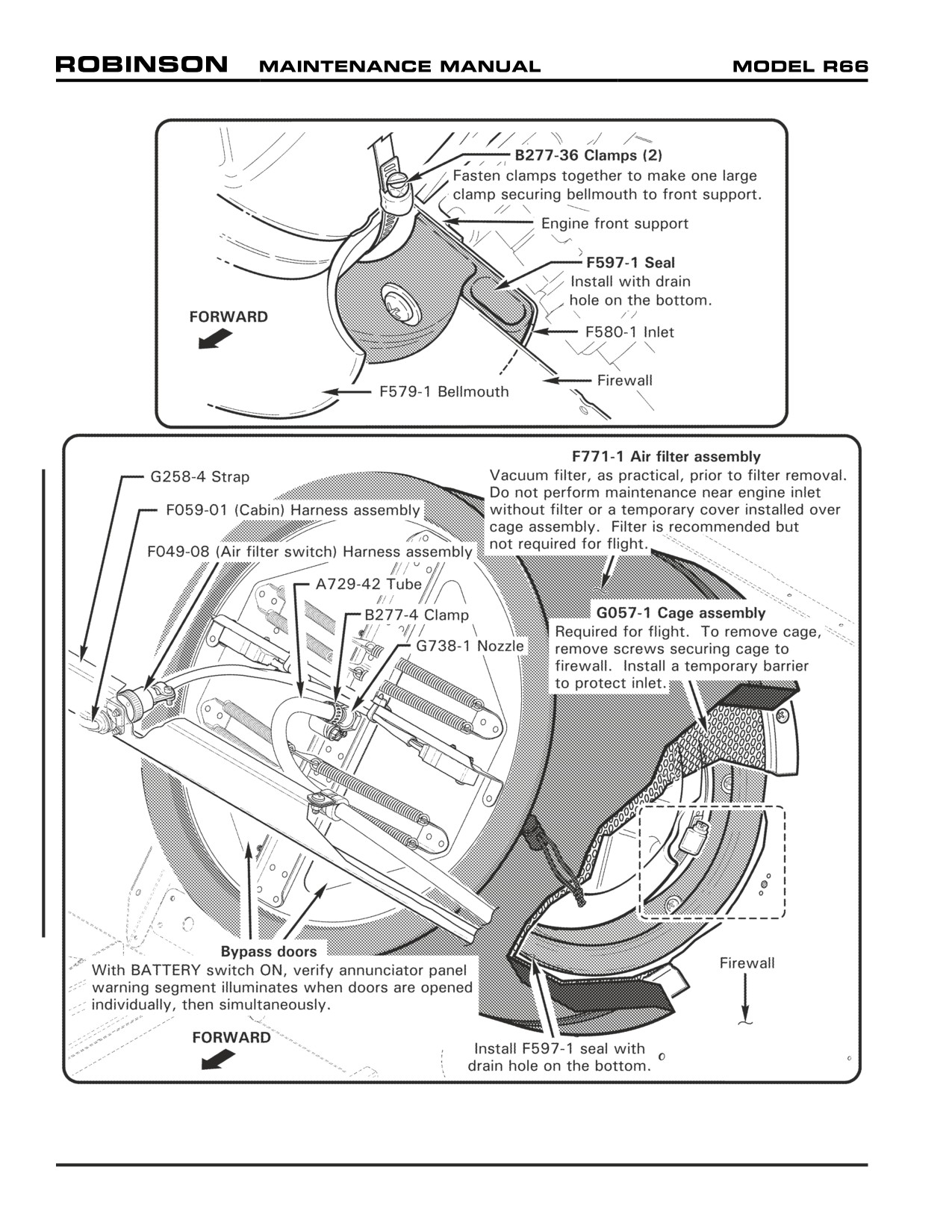
FIGURE 71-3 INDUCTION
Page 71.10
Chapter 71 Powerplant
71-20 Induction
CAUTION
Never operate engine without G057-1 cage assembly installed.
F771-1 filter assembly not required for flight.
CAUTION
Do not perform maintenance near engine inlet without either a
filter assembly or a temporary cover installed on G057-1 cage
assembly. Contact Rolls-Royce Customer Support if foreign
objects enter inlet.
71-21 Air Filter Assembly
Refer to R66 Illustrated Parts Catalog (IPC) Figure 71-9.
NOTE
Replace F771-1 air filter assembly “on-condition”.
A. Removal
1. Remove tailcone cowling assembly per Section 53-23. Open main rotor gearbox
compartment access door.
2. Refer to Figure 71-3. Vacuum exterior of F771-1 filter assembly.
3. Disconnect F049-08 (air filter switch) electrical harness plug from F059-01 (cabin)
harness at G258-4 strap.
4. Loosen B277-4 clamp securing A729-42 tube to G738-1 nozzle; pull tube off of
nozzle.
5. Pull filter forward off of G057-1 cage assembly.
B.
Installation
1. Refer to Figure 71-3. Pull F771-1 filter assembly aft over G057-1 cage assembly.
2. Install B277-4 clamp and A729-4 tube onto G738-1 nozzle and tighten clamp. Verify
security.
3. Connect F049-08 (air filter switch) electrical harness plug to F059-01 (cabin) harness
at G258-4 strap.
4. Turn BATTERY switch ON. To test air bypass warning circuit, verify annunciator
panel warning segment illuminates when bypass doors are opened individually, then
simultaneously. Turn BATTERY switch OFF.
5. Install tailcone cowling assembly per Section 53-23. Close main rotor gearbox
compartment access door.
6. Perform compressor rinse per RR300 Series Operation and Maintenance Manual (OMM).
Chapter 71 Powerplant
Page 71.11
71-22 Cage Assembly
Refer to R66 Illustrated Parts Catalog (IPC) Figure 71-9.
A. Removal
1. Remove tail rotor drive fan shaft per Section 65-10.
2. Remove air filter assembly per Section 71-21.
3. Refer to Figure 71-3. Remove hardware securing G057-1 cage assembly to firewall
and remove cage. Install suitable barrier to prevent foreign objects from entering
engine inlet.
B. Installation
1. Refer to Figure 71-3. Remove barrier, position G057-1 cage assembly against
firewall, and install hardware securing cage to firewall. Verify security.
2. Install air filter assembly per Section 71-21.
3. Install tail rotor drive fan shaft per Section 65-10.
71-23 Engine Inlet Bellmouth
Refer to R66 Illustrated Parts Catalog (IPC) Figure 71-11.
A. Removal
1. Remove engine per Section 75-10.
2. Refer to Figure 71-3. Remove F579-1 bellmouth cover and loosen B277-36 clamps
securing bellmouth to engine front support. Remove bellmouth and clamps.
3. Remove hardware securing F597-1 seal and F580-1 inlet to engine front support.
Remove seal and inlet. Install cover over front support.
B. Installation
1. Refer to Figure 71-3. Remove engine front support cover, install F580-1 inlet and
F597-1 seal (drain hole on bottom) on front support, and install hardware. Verify
security.
2. Install B277-36 clamps and F579-1 bellmouth over front support flange, and tighten
clamps. Verify security.
3. Install engine per Section 71-10.
Page 71.12
Chapter 71 Powerplant
Intentionally Blank
Chapter 71 Powerplant
Page 71.13
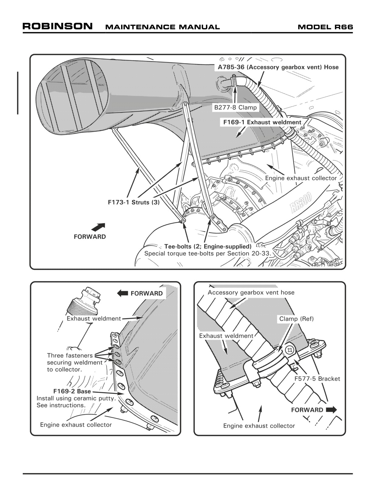
FIGURE 71-4 EXHAUST
Page 71.14
Chapter 71 Powerplant
71-30 Exhaust Weldment
Refer to R66 Illustrated Parts Catalog (IPC) Figure 71-13.
A. Removal
1. Remove engine cowling assembly per Section 53-21.
2. Refer to Figure 71-4. Remove hardware securing F173-1 struts to F169-1 exhaust
weldment and engine, and remove struts.
3. Loosen B277-8 clamp securing A785-36 (accessory gearbox vent) hose to exhaust; pull
hose off of exhaust weldment.
4. Remove three fasteners securing exhaust weldment to engine exhaust collector.
Carefully lift exhaust weldment up and off of F169-2 base flange, and remove exhaust
weldment.
5. As required, remove hardware securing base and F577-5 bracket to exhaust collector
and remove base. Install exhaust collector cover.
B.
Installation
1. Refer to Figure 71-4. If F169-2 base is installed, proceed to step 3. Verify base and
engine exhaust collector mating surfaces are clean and dry, and lay 0.25 inch bead
7020-3 ceramic putty on top of exhaust collector flange.
2. Position F169-2 base and F577-5 bracket on exhaust collector and install hardware.
Verify security. Remove excess putty.
3. Position F169-1 exhaust weldment on base and install three fasteners securing exhaust
weldment to exhaust collector.
4. Install hardware securing F173-1 struts to exhaust weldment and engine. Special torque
engine tee-bolts per Section 20-33.
5. Position A785-36 (accessory gearbox vent) hose with B277-8 clamp over exhaust
weldment vent tube. Orient clamp so clamp’s fitting, and any slight bunching of hose,
is on top of vent tube, and tighten clamp. Verify security.
6. Install engine cowling assembly per Section 53-21.
Chapter 71 Powerplant
Page 71.15
71-40 Accessories
71-41 Starter-Generator
Refer to R66 Illustrated Parts Catalog (IPC) Figure 71-15.
A. Removal
1. Remove engine cowling assembly per Section 53-21.
2. Refer to Figure 71-1. Verify heat shrink stamping is legible (or mark wires and
cables) and remove hardware securing wires and cables to starter-generator studs.
3. Remove starter-generator per RR300 Series Operation and Maintenance Manual (OMM).
B. Installation
1. Install starter-generator per RR300 Series Operation and Maintenance Manual (OMM).
2. Refer to Figure 71-1. Install wires and cables on starter-generator studs according to
stamping. Install hardware, special torque nuts per Section 20-33, and torque stripe
per Figure 5-1.
3. Install engine cowling assembly per Section 53-21.
71-42 Generator Control Unit (GCU)
Refer to R66 Illustrated Parts Catalog (IPC) Figure 71-17.
A. Removal
1. Open baggage compartment door. Remove hardware securing G248-1 cover to
inner compartment and remove cover.
2. Disconnect F049-03 (GCU) electrical harness plug from GCU. Remove mounting
hardware, and remove GCU. Cap receptacles.
B. Installation
1. Open baggage compartment door. Position GCU on inner compartment shelf and
install mounting hardware. Verify security.
2. Remove caps and connect F049-03 (GCU) electrical harness plug to GCU.
NOTE
Verify MS3106R24-28S plug is fully-engaged in GCU receptacle.
Rotate plug collar until tight.
3. Install hardware securing G248-1 cover to inner compartment. Close and secure
baggage door.
Page 71.16
Chapter 71 Powerplant
71-43 Engine Monitoring Unit (EMU)
Refer to R66 Illustrated Parts Catalog (IPC) Figure 71-19.
NOTE
The electronic monitoring unit (EMU) is a serialized component
assigned to the engine. When removing the engine, remove the
engine's EMU per Section 71-43, as required.
A. Removal
1. Remove hardware securing F003-4 (RH) seat back assembly to cabin.
2. Disconnect F059-01 (cabin) electrical harness "EMU" plug and F049-07 (USB)
harness plug from EMU.
3. Remove hardware securing EMU to bulkhead and remove EMU. Cap receptacles.
B.
Installation
1. Remove caps, position EMU on bulkhead, and install hardware. Verify security.
2. Connect F059-01 (cabin) electrical harness "EMU" plug and F049-07 (USB) harness
plug to EMU.
3. Turn BATTERY switch ON. After 10 seconds press annunciator panel test button;
verify EMU amber warning segment illuminates, and is solid, indicating normal EMU
operation. (See R66 Pilot's Operating Handbook Section 7 for complete description.)
Turn BATTERY switch OFF.
4. Install hardware securing F003-4 (RH) seat back assembly to cabin.
C. Downloading EMU Data
NOTE
An EMU USB receptacle is located inside the aft right seat
baggage compartment, on the underside of the aft ledge. Use a
flashlight and mirror when inserting USB cable into receptacle.
Download summary or diagnostic data per RR300 Series Operation and Maintenance
Manual (OMM).
Chapter 71 Powerplant
Page 71.17
Intentionally Blank
Page 71.18
Chapter 71 Powerplant
CHAPTER 75
ENGINE AIR SYSTEMS
Section Title
Page
75-00
Description
75.1
75-10
Engine Anti-Ice
75.1
25 OCT 2010
Chapter 75 Engine Air Systems
Page 75.i
Intentionally Blank
Page 75.ii
Chapter 75 Engine Air Systems
25 OCT 2010
CHAPTER 75
ENGINE AIR SYSTEMS
75-00 Description
This chapter includes a description of the engine anti-ice system. Refer to RR300 Series
Operation and Maintenance Manual (OMM) and manufacturer’s maintenance publications for
system-specific inspection, repair, and maintenance procedures.
The Rolls-Royce engine model 250-C300/A1 anti-ice system provides hot compressor discharge
air to the compressor front support. Areas of the front support are subject to ice formation
when the engine is operated near or below freezing temperatures and visible moisture is present.
An anti-ice switch located on the cyclic box cover is selected by the pilot in certain conditions
(see R66 Pilot's Operating Handbook).
The engine anti-ice system includes an air valve, a solenoid valve, and a pressure switch. The
air valve is mounted on top of the compressor scroll; the solenoid valve and pressure switch
are mounted on top of the compressor. When anti-ice is switched "ON", the solenoid valve de-
energizes, the pressure-activated air valve opens, the pressure switch closes which illuminates
the green anti-ice segment on the annunciator panel, and hot, compressed-air is routed to
hollow passages in the front support vanes and center hub.
Anti-ice system operation will result in some performance degradation due to hot induction air
and reduced air-volume reaching the power and gas producing turbine stages.
The anti-ice solenoid valve is electrically-closed, or powered-off. Anti-ice will automatically
function in the event of an electrical failure.
75-10 Engine Anti-Ice
See RR300 Series Operation and Maintenance Manual (OMM) for anti-ice system maintenance.
25 OCT 2010
Chapter 75 Engine Air Systems
Page 75.1
Intentionally Blank
Page 75.2
Chapter 75 Engine Air Systems
25 OCT 2010
CHAPTER 76
ENGINE CONTROLS
Section Title
Page
76-00
Description
76.1
76-10
Fuel Control Unit (FCU)
76.1
76-11
FCU Throttle Control Rigging
76.3
76-12
FCU Fuel Cutoff Control Rigging
76.3
76-20
Power Turbine Governor (PTG)
76.5
76-21
PTG Control Rigging
76.5
76-22
PTG Rigging Check
76.7
25 OCT 2010
Chapter 76 Engine Controls
Page 76.i
Intentionally Blank
Page 76.ii
Chapter 76 Engine Controls
25 OCT 2010
CHAPTER 76
ENGINE CONTROLS
76-00 Description
A twist grip throttle control is located on each collective stick. The controls are interconnected
and actuate the Rolls-Royce engine model 250-C300/A1 fuel control input lever via a push-pull
cable. The throttle is normally not used for control but is set either fully closed (idle position)
or fully open.
The engine incorporates a hydromechanical governor which attempts to maintain 100% engine
output shaft RPM when the throttle is in the open position. A linkage provides the power
turbine governor with collective inputs to help anticipate changing power demands.
Large power changes or varying environmental conditions may cause the governor RPM setting
to vary by a few percent. A momentary toggle switch (beep switch) on the collective stick is
provided to trim, or "beep", the governor setting to the desired RPM. The switch controls an
actuator which adjusts the linkage between the collective and power turbine governor.
The governor controls RPM under normal conditions. It may not prevent over- or under-speed
conditions generated by aggressive flight maneuvers or rapid power changes.
Other engine controls include a push-pull fuel cutoff control on the console face, a start button
on the pilot's collective, a key-type igniter switch, and an anti-ice switch.
76-10 Fuel Control Unit (FCU)
Refer to R66 Illustrated Parts Catalog (IPC) Figure 76-1.
A. Removal
1. Pull fuel valve OFF. Remove engine cowling assembly per Section 53-21.
2. Refer to Figure 76-1. Remove fasteners securing C522-10 throttle and A522-10 fuel
cutoff control inner wires to FCU throttle and fuel cutoff levers.
3. Remove fasteners securing control housings and AN742-4 clamps to F577 bracket
assemblies, as required.
4. Remove FCU per RR300 Series Operation and Maintenance Manual (OMM).
5. If sending FCU to repair facility, remove F147-1 (minimum throttle stop) screw and
D930-2 spring.
B.
Installation
1. If removed: Install F147-1 (minimum throttle stop) screw, special torque screw per
Section 20-33, and torque stripe per Figure 5-1. Install D930-2 spring.
2. Install FCU per RR300 Series Operation and Maintenance Manual (OMM).
3. Perform throttle control rigging per Section 76-11.
4. Perform fuel cutoff control rigging per Section 76-12.
5. Push fuel valve ON.
Chapter 76 Engine Controls
Page 76.1
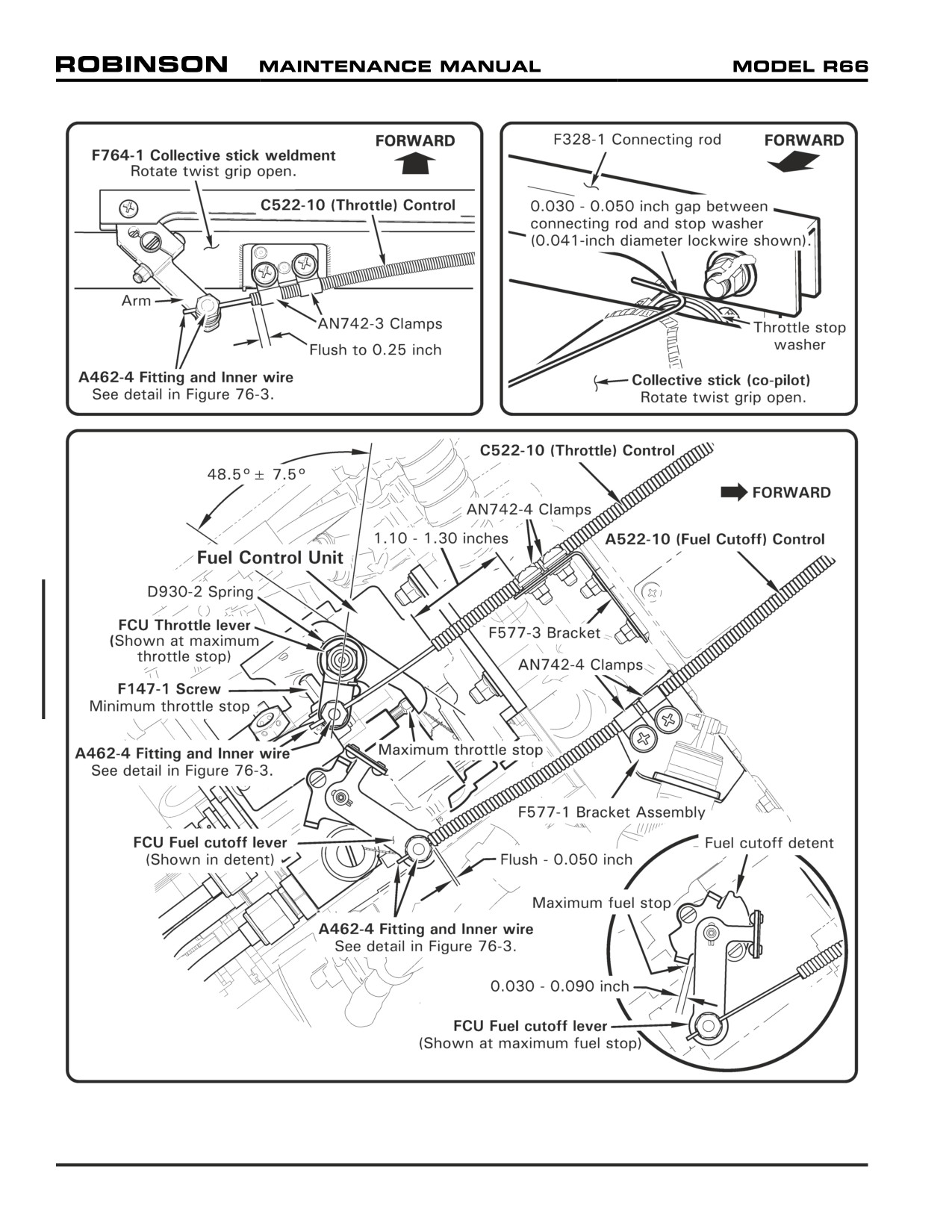
FIGURE 76-1 FUEL CONTROL UNIT
Page 76.2
Chapter 76 Engine Controls
76-11 FCU Throttle Control Rigging
1.
Remove engine cowling assembly per Section 53-21. Remove F461-1 collective cross
tube cover and (copilot) F680-1 collective cover assembly (see Section 6-70).
2.
Refer to Figure 76-1. Verify FCU throttle lever rigging angle is 48.5° ± 7.5°. As
required, remove hardware securing serrated levers and reposition to proper angle.
Install hardware, special torque nut per Section 20-33, & torque stripe per Figure 5-1.
3.
Remove palnuts and loosen nuts securing A462-4 fittings and C522-10 (throttle) control
inner wire to collective arm and to FCU throttle lever.
4.
Position forward end of control housing flush-0.25 inch at or beyond edge of outboard
AN742-3 clamp and install fasteners securing housing and clamps to F764-1 collective
stick weldment.
5.
Refer to detail in Figure 76-3. Rotate collective stick twist grip open. Position inner
wire 0.10-0.30 inch beyond outboard edge of fitting in collective arm, and special
torque fitting nut per Section 20-33. Install palnut, standard torque per Section 20-32,
& torque stripe per Figure 5-1.
6.
Position aft end of control housing 1.10-1.30 inches beyond edge of aft AN742-4 clamp
and install fasteners securing housing and clamps to F577-3 bracket.
7.
Refer to detail in Figure 76-3. Rotate twist grip closed; rotate and hold FCU throttle
lever to contact idle stop. Verify sufficient inner wire beyond aft edge of fitting, and
special torque fitting nut per Section 20-33.
8.
Rotate twist grip open; verify FCU throttle lever contacts maximum throttle stop,
and 0.030-0.050 inch gap between F328-1 connecting rod and throttle stop washer.
Reposition fitting on wire as required until proper rod-to-washer gap, and FCU throttle
lever contacts maximum throttle stop with twist grip open, and idle stop with twist grip
closed.
9.
Install fitting palnut, standard torque per Section 20-32, and torque stripe per Figure
5-1. Trim control wire 0.10-0.30 inch beyond aft edge of fitting.
10.
Install collective cross tube cover and collective cover assembly. As required, perform
FCU fuel cutoff control rigging per Section 76-12, or install engine cowling assembly
per Section 53-21.
76-12 FCU Fuel Cutoff Control Rigging
1. Remove engine cowling assembly per Section 53-21.
2. Refer to Figure 76-1. Remove palnut and loosen nut securing A462-4 fitting and A522-
10 (fuel cutoff) control inner wire to FCU fuel cutoff lever.
3. Rotate FCU fuel cutoff lever into OFF detent; pull fuel cutoff control knob OFF (at
lower console). Position end of control housing flush-0.050 inch from forward edge of
fitting and install fasteners securing housing and AN742-4 clamps to F577-1 bracket
assembly.
4. Refer to detail in Figure 76-3. Verify sufficient inner wire beyond aft edge of fitting, and
special torque fitting nut per Section 20-33.
25 OCT 2010
Chapter 76 Engine Controls
Page 76.3
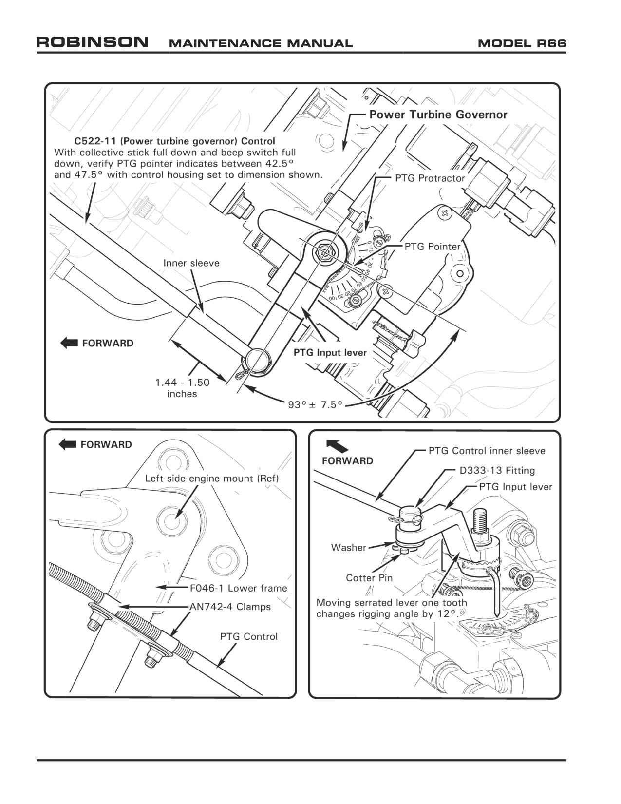
FIGURE 76-2 POWER TURBINE GOVERNOR
Page 76.4
Chapter 76 Engine Controls
25 OCT 2010
76-12 FCU Fuel Cutoff Control Rigging (continued)
5. Push fuel cutoff control knob ON and verify FCU fuel cutoff lever-to-maximum fuel
stop clearance is 0.030-0.090 inch. Reposition fitting on wire as required until FCU
fuel cutoff lever rests in detent when control is OFF and has required clearance from
maximum fuel stop when control is ON.
6. Install fitting palnut, standard torque per Section 20-32, and torque stripe per Figure
5-1. Trim control wire 0.10-0.30 inch beyond aft edge of fitting.
7. Install engine cowling assembly per Section 53-21.
76-20 Power Turbine Governor (PTG)
Refer to R66 Illustrated Parts Catalog (IPC) Figures 76-5 and 76-7.
A. Removal
1. Remove engine cowling assembly per Section 53-21.
2. Refer to Figure 76-2. Remove cotter pin and washer securing C522-11 (power turbine
governor) control inner sleeve and D333-13 fitting to PTG input lever.
3. Remove fasteners securing control housing and AN742-4 clamps to F046-1 lower frame,
as required.
4. Remove PTG per RR300 Series Operation and Maintenance Manual (OMM).
B.
Installation
1. Install PTG per RR300 Series Operation and Maintenance Manual (OMM).
2. Perform PTG control rigging per Section 76-21.
76-21 PTG Control Rigging
1. Remove engine cowling assembly per Section 53-21. Detach center back rest assembly
hook and loop tape (Velcro) at bottom; slide back rest assembly up and out of keyhole
slots. Remove F474-2 middle seat cover (see Section 6-70).
2. Refer to Figure 76-2. Verify PTG input lever rigging angle is 93.0° ± 7.5°. As required,
remove hardware securing serrated levers and reposition to proper angle. Install
hardware, special torque nut per Section 20-33, and torque stripe per Figure 5-1.
3. Refer to Figure 76-3. Remove palnut and loosen nut securing A462-4 fitting and C522-
11 (power turbine governor) control inner wire to F822-1 bellcrank assembly.
4. Position PTG pointer to indicate 45° on PTG protractor. Position aft end of control
housing 1.44-1.50 inches from forward edge of D333-13 fitting and install fasteners
securing housing and AN742-4 clamps to F046-1 lower frame.
5. Position forward end of control housing flush-0.25 inch at or below edge of bottom
AN742-3 clamp and install fasteners securing housing and clamps to F381-6 bracket.
6. Turn BATTERY switch ON. With collective stick full down, “beep” collective toggle
switch to full down. Turn BATTERY switch OFF.
25 OCT 2010
Chapter 76 Engine Controls
Page 76.5
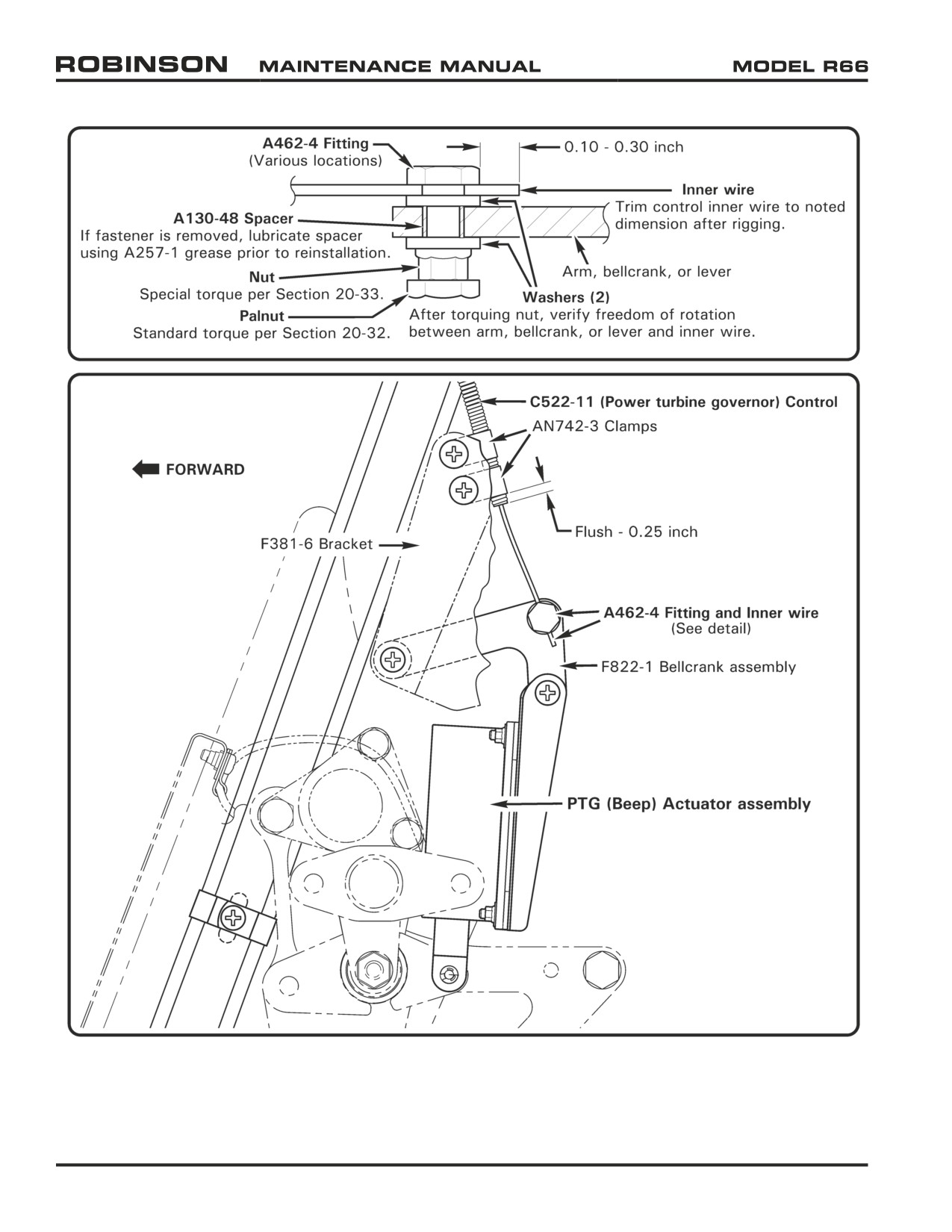
FIGURE 76-3 PTG (BEEP) ACTUATOR ASSEMBLY
Page 76.6
Chapter 76 Engine Controls
25 OCT 2010
76-21 PTG Control Rigging (continued)
7. Verify PTG pointer indicates 45° on PTG protractor, verify sufficient inner wire beyond
bottom edge of bellcrank fitting, and special torque fitting nut per Section 20-33.
8. Install palnut, standard torque per Section 20-32, and torque stripe per Figure 5-1. Trim
control wire 0.10-0.30 inch beyond bottom of fitting.
9. Perform PTG rigging check per Section 76-22.
10. Install engine cowling assembly per Section 53-21. Install middle seat cover. Install
back rest assembly in keyhole slots and slide down; press firmly on back rest assembly
hook and loop tape at bottom. Verify security.
76-22 PTG Rigging Check
1. Turn BATTERY switch ON.
2. Refer to Figure 76-2. With collective stick full down, “beep” collective toggle switch to
full down. Verify PTG pointer indicates between 42.5° and 47.5° on PTG protractor.
Turn BATTERY switch OFF.
3. Adjust PTG control rigging as required per Section 76-21; repeat previous steps until
PTG is rigged for proper mechanical range.
4. Run-up helicopter per R66 Pilot's Operating Handbook, Section 4. Verify “beep” range
is 97 to 103% rotor RPM with collective full down and twist grip open.
5. Adjust PTG control rigging as required per Section 76-21; repeat previous steps until
PTG is rigged for proper operational range.
25 OCT 2010
Chapter 76 Engine Controls
Page 76.7
Intentionally Blank
Page 76.8
Chapter 76 Engine Controls
25 OCT 2010
CHAPTER 79
ENGINE OIL SYSTEM
Section Title
Page
79-00
Description
79.1
79-10
Scroll and Fanwheel Assemblies
79.3
79-11
Fanwheel-to-Inlet Gaps
79.3
79-20
Oil Tank Assembly
79.5
79-21
Oil Temperature Sender
79.6
79-22
Sight Gage
79.7
79-30
Engine Oil Cooler
79.7
79-40
Engine Oil Line Assemblies and Fittings
79.8
Chapter 79 Engine Oil System
Page 79.i
Intentionally Blank
Page 79.ii
Chapter 79 Engine Oil System
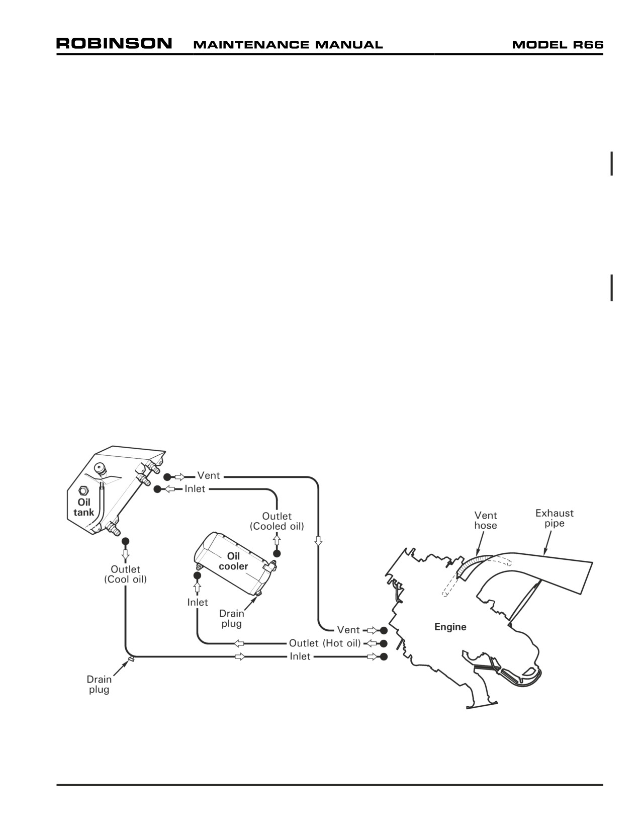
CHAPTER 79
ENGINE OIL SYSTEM
79-00 Description
The R66 helicopter has a dry-sump engine oil system. Oil is stored in a remote tank located in
the main rotor gearbox compartment. Refer to Section 12-60 for oil servicing instructions. A
Rolls-Royce-supplied oil temperature sender is mounted on the inboard side of the oil tank.
Oil circulates through the engine oil system via three oil delivery lines. Refer to Figure 79-1.
Cool oil exits the oil tank and enters the engine, hot oil exits the engine and enters the engine
oil cooler, and cooled oil exits the oil cooler and returns to the oil tank. An oil tank vent line is
plumbed to the engine accessory gearbox, which is vented to the exhaust pipe.
The engine oil cooler has an internal thermostat and pressure relief valve. The thermostat
maintains normal system operating pressure by allowing cool oil to bypass the heat exchanger
and return to the oil tank. Higher than normal system pressure will open a pressure relief valve.
When draining the oil system, residual oil is trapped in the bottom corner of the oil cooler due
to the oil cooler installation angle in the R66. An oil cooler drain plug allows the technician to
drain trapped oil during servicing.
The engine oil system includes an oil pump, oil filter and regulating valve, an oil sump tank, a
check valve, and two magnetic plug inserts. Refer to RR300 OMM for a complete description
of the engine oil system.
FIGURE 79-1 ENGINE OIL SYSTEM SCHEMATIC
Chapter 79 Engine Oil System
Page 79.1
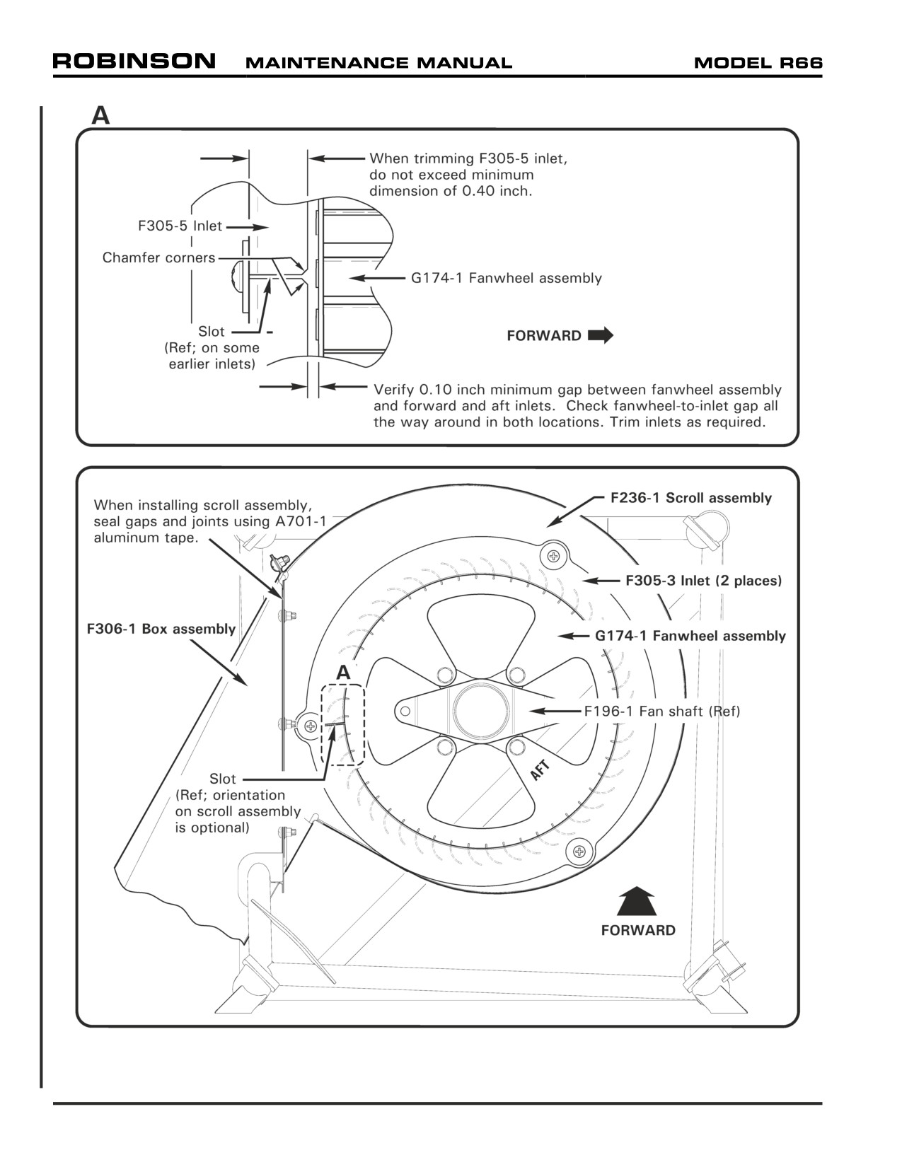
FIGURE 79-2 SCROLL AND FANWHEEL ASSEMBLIES
Page 79.2
Chapter 79 Engine Oil System
79-10 Scroll and Fanwheel Assemblies
Refer to R66 Illustrated Parts Catalog (IPC) Figure 79-1.
A. Removal
1. Remove F196-1 fan shaft per Section 65-10.
2. Refer to Figure 79-2. Remove perimeter screws securing F236-1 scroll assembly to
F306-1 box assembly.
3. Remove aluminum tape sealing gaps & joints, or gently pull scroll away from box
assembly and, using a scribe or similar sharp instrument, tear aluminum tape sealing
gaps & joints. Remove scroll, with G174-1 fanwheel assembly inside, up through
frame.
4. Remove hardware securing forward or aft F305-5 inlet to scroll; remove inlet & fanwheel.
Remove damaged aluminum tape from scroll and box assembly.
B.
Installation
1. Refer to Figure 79-2. Observing “AFT” orientation marking on fanwheel plate, place
G174-1 fanwheel assembly inside F236-1 scroll assembly accordingly. Position F305-5
inlets on scroll and install hardware. Verify security.
2. Lower scroll, with fanwheel inside, through frame and install hardware securing scroll
to F306-1 box assembly. Verify security. Seal gaps & joints using A701-1 aluminum
tape.
3. Install F196-1 fan shaft per Section 65-10.
79-11 Fanwheel-to-Inlet Gaps
A. Measuring Gap
1. Remove tailcone cowling assembly per Section 53-23.
2. Refer to Figure 79-2. Verify 0.10 inch minimum gap between G174-1 fanwheel
assembly and forward and aft F305-5 inlets. Check gap all the way around; rotate
fanwheel and check gap again (several positions). If gap is within limits at forward
and aft inlets, no further action is required.
3. Verify proper tail rotor driveline shimming per Section 65-30.
4. Trim inlets as required per Part B.
5. Install tailcone cowling assembly per Section 53-23.
Chapter 79 Engine Oil System
Page 79.3

FIGURE 79-3 ENGINE OIL SYSTEM
Page 79.4
Chapter 79 Engine Oil System
79-11 Fanwheel-to-Inlet Gaps (continued)
B.
Trimming Inlets
1. Refer to Figure 79-2. Remove hardware securing F305-5 inlets to F236-1 scroll
assembly.
2. If inlets are slotted, carefully twist inlets over F196-1 fan shaft and remove inlets. If
inlets are not slotted, remove hardware securing fan shaft to C947-3 plate assemblies,
noting hardware removed, and remove inlets.
3. Refer to Figure 79-2, Detail A. Trim inlets as required to meet minimum fanwheel-
to-inlet gap. Do not exceed minimum inlet dimensions.
4. Refer to Section 20-70. Smooth inlet edges and coat bare metal with primer. Touch-
up primed area using dark gray Dupont Imron polyurethane enamel in accordance
with paint manufacturer’s recommendations.
5. If inlets are slotted, carefully twist inlets over fan shaft and install hardware securing
inlets to scroll assembly (slot orientation is optional). Verify security.
6. If inlets are not slotted, install inlets around fan shaft and install hardware securing
inlets to scroll assembly. Verify security. Install hardware securing fan shaft to
plate assemblies, standard torque nuts and palnuts per Section 20-32, and torque
stripe per Figure 5-1.
7. Measure fanwheel-to-inlet gaps per Part A. Repeat procedure as required for minimum
0.10 inch gap at forward and aft inlets.
79-20 Oil Tank Assembly
Refer to R66 Illustrated Parts Catalog (IPC) Figure 79-5.
A. Removal
1. Drain engine oil per Section 12-60.
2. Remove tailcone cowling assembly per Section 53-23. Open main rotor gearbox
compartment access door.
3. Refer to Figure 79-3. Cut and discard safety wire securing tube to G689-1 oil tank
assembly scupper drain. Pull tube off of drain.
4. Disconnect harness assembly plug from MS28034-1 oil temperature sender (located on
inboard side of tank).
5. Remove hardware securing line assembly clamps.
6. Loosen F723-1, F723-3, and F723-4 line assembly B-nuts from engine, F649-1 oil
cooler, and tank fittings; disconnect lines from tank fittings and plug lines.
7. Remove nuts securing tank fittings to firewall.
8. Remove hardware securing tank tabs to F384-3 angles. Remove tank through access
door and cap fittings.
Chapter 79 Engine Oil System
Page 79.5
79-20 Oil Tank Assembly (continued)
B. Installation
1. Refer to Figure 79-3. Remove caps from G689-1 oil tank assembly fittings.
2. Torque check union at oil cooler, and torque check engine (oil line) unions and check
valve per Section 20-33.
3. Insert tank through main rotor gearbox compartment access door. Install hardware
securing tank tabs to F384-3 angles.
4. Install nuts securing tank fittings to firewall and special torque nuts per Section 20-33.
5. Remove plugs and connect F723-1, F723-3, and F723-4 line assembly B-nuts to tank
fittings. Special torque B-nuts at tank, F649-1 oil cooler, and engine per Section 20-33
and torque stripe fittings.
6. Install hardware securing line assembly clamps.
7. Connect harness assembly plug to oil temperature sender (located on inboard side of
tank).
8. Fit tube onto tank scupper drain. Wrap tube with two turns 0.032-inch diameter lockwire
and safety tube to drain.
9. Service engine oil per Section 12-60.
10. Install tailcone cowling assembly per Section 53-23.
79-21 Oil Temperature Sender
Refer to R66 Illustrated Parts Catalog (IPC) Figure 79-5.
A. Removal
1. Drain engine oil per Section 12-60.
2. Remove tailcone cowling assembly per Section 53-23.
3. Refer to Figure 79-3. Disconnect harness assembly plug from MS28034-1 oil
temperature sender (located on inboard side of G689-1 oil tank assembly).
4. Remove sender and gasket from tank, and discard gasket.
5. Tape sender opening to protect tank from contaminants.
B. Installation
1. Refer to Figure 79-3. Remove tape from G689-1 oil tank assembly sender opening
and verify tank interior is free of contaminants.
2. Install new gasket on MS28034-1 oil temperature sender, and install sender in
inboard side of tank. Special torque sender per Section 20-33.
3. Connect harness assembly plug to sender.
4. Service engine oil per Section 12-60.
5. Install tailcone cowling assembly per Section 53-23.
Page 79.6
Chapter 79 Engine Oil System
79-22 Sight Gage
Refer to R66 Illustrated Parts Catalog (IPC) Figure 79-5.
A. Removal
1. Drain engine oil per Section 12-60.
2. Refer to Figure 79-3. Remove B563-2 sight gage and o-ring from G689-1 oil tank
assembly. Discard o-ring.
3. Tape gage opening to protect tank from contaminants.
B. Installation
1. Refer to Figure 79-3. Remove tape from G689-1 oil tank assembly gage opening and
verify tank interior is free of contaminants.
2. Lubricate new o-ring using approved turbine engine oil per R66 Pilot’s Operating
Handbook (POH) Section 8. Install o-ring on B563-2 sight gage, and install gage in
tank. Special torque gage per Section 20-33.
3. Service engine oil per Section 12-60.
79-30 Engine Oil Cooler
Refer to R66 Illustrated Parts Catalog (IPC) Figure 79-7.
A. Removal
1. Drain engine oil per Section 12-60.
2. Refer to Figure 79-3. Remove fasteners securing F649-1 oil cooler to F309-1 box
assembly.
3. Remove hardware securing line assembly clamps.
4. Support oil cooler without damaging oil cooler fins. Loosen F723-2 and F723-4 line
assembly B-nuts at engine, oil cooler, and G689-1 oil tank assembly fitting; disconnect
lines at oil cooler unions. Cap unions and plug lines.
B.
Installation
1. Refer to Figure 79-3. Remove F649-1 oil cooler union caps. Torque check oil cooler
unions and engine (oil line) union or check valve (early R66s) per Section 20-33.
2. Remove plugs and connect F723-2 and F723-4 line assembly B-nuts to oil cooler fittings.
Special torque B-nuts at tank, oil cooler, and engine per Section 20-33 and torque stripe
fittings.
3. Install hardware securing line assembly clamps.
4. Install hardware securing F649-1 oil cooler to F309-1 box assembly.
5. Service engine oil per Section 12-60.
Chapter 79 Engine Oil System
Page 79.7
79-40 Engine Oil Line Assemblies and Fittings
Refer to R66 Illustrated Parts Catalog (IPC) Figure 79-9.
A. Removal
1. Drain engine oil per Section 12-60.
2. Refer to Figure 79-3. Remove hardware securing line assembly clamps.
3. Disconnect F723 line assembly B-nuts from engine, F649-1 oil cooler, and/or G689-1
oil tank assembly fittings, as required. Cap fittings and plug lines.
4. Carefully remove line assembly from engine compartment.
B.
Installation
1. Refer to Figure 79-3. Remove caps from unions. Torque check F649-1 oil cooler
unions and/or G689-1 oil tank assembly nuts per Section 20-33; torque check engine
(oil line) unions and/or check valve (early R66s) per Section 20-33, as required.
2. Remove plugs and connect F723 line assembly B-nuts to engine, oil cooler, and/or tank,
as required. Verify 0.2 inch minimum clearance between shaft weldment and firewall
grommet; verify equal gap concentrically between shaft and box assembly hole edges.
Adjust F174-1 support weldment rod ends per Section 53-31 as required. Special
torque B-nuts per Section 20-33 and torque stripe fittings.
3. Install hardware securing line assembly clamps.
4. Service engine oil per Section 12-60.
Page 79.8
Chapter 79 Engine Oil System
CHAPTER 95
INSTRUMENT SYSTEM
Section
Title
Page
95-00
Description
95.1
95-10
Pitot-Static System
95.3
95-20
Primary Instruments
95.5
95-21
Vertical Speed Indicator
95.5
95-22
Airspeed Indicator
95.5
95-23
Engine (N2) and Rotor Dual Tachometer
95.5
95-24
Altimeter
95.5
95-25
Torquemeter
95.6
95-26
Magnetic Compass
95.6
95-30
Engine Gages
95.6
95-31
N1 Tachometer
95.6
95-32
Measured Gas (Turbine) Temperature (MGT) Gage
95.6
95-33
Engine Oil Pressure Gage
95.6
95-34
Engine Oil Temperature Gage
95.6
95-35
Fuel Quantity Gage
95.6
95-40
Additional Standard Indicating Equipment
95.7
95-41
Clock
95.7
95-42
Ammeter
95.7
95-43
Outside Air Temperature (OAT) Gage/Voltmeter
95.7
95-44
Hourmeters
95.7
95-50
Instrument Markings
95.7
95-60
Troubleshooting Guide
95.7
25 OCT 2010
Chapter 95 Instrument System
Page 95.i
Intentionally Blank
Page 95.ii
Chapter 95 Instrument System
25 OCT 2010
CHAPTER 95
INSTRUMENT SYSTEM
95-00 Description
Standard primary instruments are a vertical speed indicator, airspeed indicator, engine (N2)
and rotor dual tachometer, altimeter, torquemeter, and magnetic compass. Engine gages
include an N1 tachometer, measured gas (turbine) temperature, oil pressure, oil temperature,
and fuel quantity. Also standard are a clock, an ammeter, a digital outside air temperature
gage/voltmeter, and an hourmeter. An additional hourmeter is located outboard of the pilot's
seat. Both hourmeters require main gearbox oil pressure to activate. The outboard hourmeter
is collective activated and is approved for recording time in service. Space is provided for
optional instruments and avionics.
The pitot-static system supplies air pressure to operate the airspeed indicator, altimeter, and
vertical speed indicator. The pitot tube is located on the front edge of the mast fairing. The
static sources are located on each side of the cabin, aft of the rear doors.
Water can be drained from pitot-static lines by removing the plastic drain plugs which are
accessible through the aft inspection panel on the underside of the cabin. Draining lines should
be required only if the airspeed indicator or altimeter appears erratic.
Pitot and static sources should be inspected frequently for bugs or other obstructions, or if
condensation appears inside connected instruments.
25 OCT 2010
Chapter 95 Instrument System
Page 95.1
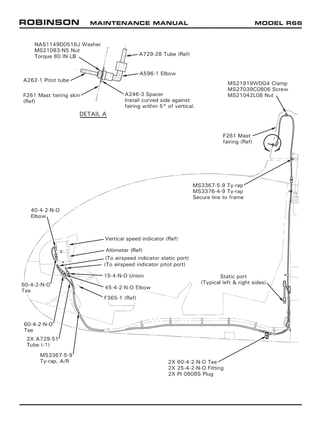
FIGURE 95-1 PITOT - STATIC SYSTEM
Page 95.2
Chapter 95 Instrument System
25 OCT 2010
95-10 Pitot-Static System
A. Pitot System Leak Test
CAUTION
Do not apply suction to pitot system or pressure to static system.
1. Open mast fairing per Section 53-22.
2. Refer to Figures 95-1 and 95-2. Seal drain hole in elbow aft of pitot tube with pressure
sensitive tape. Connect a medical syringe, with plunger withdrawn, to pitot tube via
flexible tubing.
3. SLOWLY apply pressure to pitot line by depressing syringe plunger until airspeed indicator
reads 70 knots. Release force on plunger; plunger will remain in place without need to
pinch flexible tubing.
4. Gently tap airspeed indicator glass to remove friction effects.
5. If airspeed indication drops more than 10 knots in one minute, an unacceptable leak is
indicated. SLOWLY release pressure. Locate and repair any leak(s). Retest after any
repairs.
6. Remove tape from pitot tube drain hole and verify airspeed indicator has returned to
zero.
7. Remove test equipment.
B.
Static System Leak Test
CAUTION
Airspeed indicator, altimeter, and vertical speed indicator may be
damaged if suction to static line is applied or removed rapidly.
1. Refer to Figures 95-1 and 95-2. Set altimeter to location elevation.
2. Temporarily seal left or right side static opening with pressure sensitive tape. Cover
remaining static port with a suction cup attached to a medical syringe.
3. SLOWLY apply suction to static port by withdrawing syringe plunger until altimeter
indicates 500 feet greater than location elevation. Release force on plunger, wait one
minute, and note any change in altimeter indication.
4. Change of less than 100 feet indication in one minute is acceptable. SLOWLY remove
suction from static port. Locate and repair leak(s) if altimeter indication changes 100 or
more feet in one minute. Retest after any repairs.
5. Remove test equipment.
25 OCT 2010
Chapter 95 Instrument System
Page 95.3
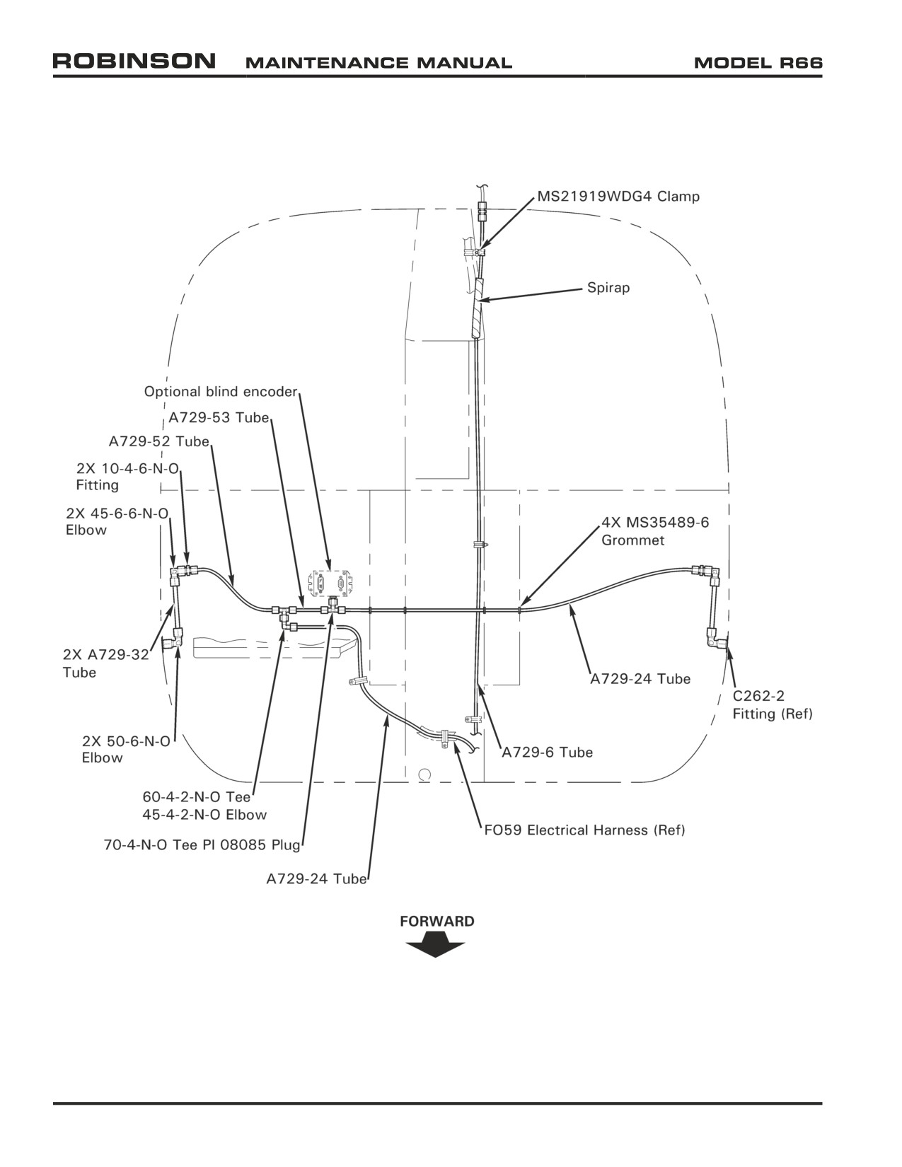
FIGURE 95-2 PITOT - STATIC SYSTEM
Page 95.4
Chapter 95 Instrument System
25 OCT 2010
95-20 Primary Instruments
95-21 Vertical Speed Indicator
The vertical speed indicator indicates rate of ascent or descent. Check vertical speed
indicator for a zero-rate needle indication when rotorcraft is in a stationary hover.
95-22 Airspeed Indicator
The airspeed indicator displays airspeed in knots and miles per hour. The airspeed
indicator operates in forward flight only; backward or lateral flight will not indicate correct
airspeed.
95-23 Engine (N2) and Rotor Dual Tachometer
CAUTION
Installation of electrical devices can affect accuracy and reliability
of electronic tachometers.
An electronic engine (N2) and rotor dual tachometer is standard. Engine tachometer signal
is provided by a transducer on the engine gearbox. Rotor tachometer signal is provided by
magnets on the main gearbox tail rotor driveline yoke. Each tachometer is on a separate
circuit with its own circuit breaker. The tachometer bus receives power from the avionics
bus or through the battery relay bypass circuit as long as the main rotor gearbox has
oil pressure. Therefore, the tachometers will receive power through the bypass circuit
whenever the rotors are turning even if the avionics bus is not powered. The bypass circuit
is disconnected from the tachometer bus when the annunciator test button is depressed.
Pressing the test button while the helicopter is running will confirm that the tachometers
are receiving power from the avionics bus.
A. Adjustment
NOTE
The dual tachometer is preset at RHC. Slight variations between
rotorcraft may require tachometer adjustment.
1. Open upper console.
2. Run-up helicopter per R66 Pilot's Operating Handbook (POH) Section 6 at 100%
engine tachometer indication.
3. Turn adjustment screw on back of tachometer clockwise to increase and
counterclockwise to decrease rotor tachometer indication
(one-half turn equals
approximately 1% change). Adjust rotor tachometer to indicate 100%.
4. Shutdown helicopter per R66 POH Section 6. Close and secure upper console.
95-24 Altimeter
The sensitive altimeter provides altitude information relative to mean sea level when the
barometric pressure correction scale is properly set. Check altimeter calibration by setting
correction scale to the current altimeter setting and checking the altimeter reading against
location elevation; they must agree within 70 feet.
25 OCT 2010
Chapter 95 Instrument System
Page 95.5
95-25 Torquemeter
The electronic torquemeter indicates percent torque. The torque sensor is an oil pressure
transducer mounted on the front of the engine's accessory gearbox.
95-26 Magnetic Compass
An internally illuminated, wet-type compass is attached to the center bow between the
windshields above the instrument panel. A compass correction card is aft of the windshield
above the pilot's seat.
95-30 Engine Gages
95-31 N1 Tachometer
The electronic N1 tachometer indicates percent RPM of the engine's gas producer section.
The N1 sensor is a sealed variable-reluctance, permanent-magnet device mounted atop the
engine's accessory gearbox adjacent to the hoisting lug.
95-32 Measured Gas (Turbine) Temperature (MGT) Gage
The measured gas temperature (MGT) gage connects to the engine's thermocouple harness
via different size connectors to ensure correct polarity. Refer to RR300 Series Operation
and Maintenance Manual (OMM) for periodic calibration requirements.
95-33 Engine Oil Pressure Gage
The engine oil pressure gage is electronic. The oil pressure sensor is a transducer mounted
on the lower front of the engine's accessory gearbox.
95-34 Engine Oil Temperature Gage
The engine oil temperature gage is electronic. The oil temperature sensor is a transducer
mounted on the inboard wall of the oil tank.
95-35 Fuel Quantity Gage
The electric fuel quantity gage indicates relative fuel quantity. The variable resistance
sender is mounted near the fuel cap.
Page 95.6
Chapter 95 Instrument System
25 OCT 2010
95-40 Additional Standard Indicating Equipment
95-41 Clock
A manually set electric analog clock is standard equipment; a digital clock is optional.
95-42 Ammeter
The ammeter indicates electrical system loads. System load is measured at the shunt
located on the left side of the vertical firewall in the engine compartment.
95-43 Outside Air Temperature (OAT) Gage/Voltmeter
NOTE
No cutting or splicing of OAT probe wires is permitted.
The outside air temperature gage is connected via a calibrated, twisted pair wiring harness
to a stainless steel probe protruding from the chin.
95-44 Hourmeters
Two hourmeters are standard. One hourmeter is mounted above the ammeter and is
activated by main gearbox oil pressure. Another hourmeter on the horizontal panel outboard
of the pilot's seat is activated by a combination of main gearbox oil pressure and a raised
collective and is approved for recording time in service.
95-50 Instrument Markings
See R66 Pilot's Operating Handbook (POH) Section 2 for instrument markings.
95-60 Troubleshooting Guide
Vertical Speed Indicator
Climb indication with no return to
No Indication
Erratic Indication
zero in level flight.
• Defective indicator.
• Water in static system.
• Blockage in the static line.
• Defective indicator.
Airspeed Indicator
No Indication
Erratic Indication
• Blockage of pitot tube.
• Loose pitot or static line connection.
• Disconnected pitot tube.
• Broken pitot line.
• Kinks (bends) in pitot line
• Water in pitot-static system.
under upper console.
• Defective instrument.
• Defective indicator.
Altimeter
No Indication
Erratic Indication
• Blockage in static line.
• Water in static line.
• Defective instrument.
25 OCT 2010
Chapter 95 Instrument System
Page 95.7
Intentionally Blank
Page 95.8
Chapter 95 Instrument System
25 OCT 2010
CHAPTER 96
ELECTRICAL SYSTEM
Section Title
Page
96-00
Description
96.1
96-10
Battery
96.2
96-20
External Power
96.5
96-30
Starter and Ignition System
96.5
96-40
Lighting System
96.6
96-50
Annunciator Panel
96.6
96-60
Low Rotor RPM Warning Unit Adjustment
96.7
96-70
Audio System
96.7
96-80
Engine Monitoring Unit (EMU)
96.8
96-90
Emergency Locator Transmitter (ELT)
96.8
96-100
Electrical Load Analysis
96.9
Chapter 96 Electrical System
Page 96.i