NATOPS FLIGHT MANUAL NAVY MODEL AV--8B/TAV--8B 161573 AND UP AIRCRAFT (2008) - page 13
A1-AV8BC-410-100
008 00
Change 6
Page 10
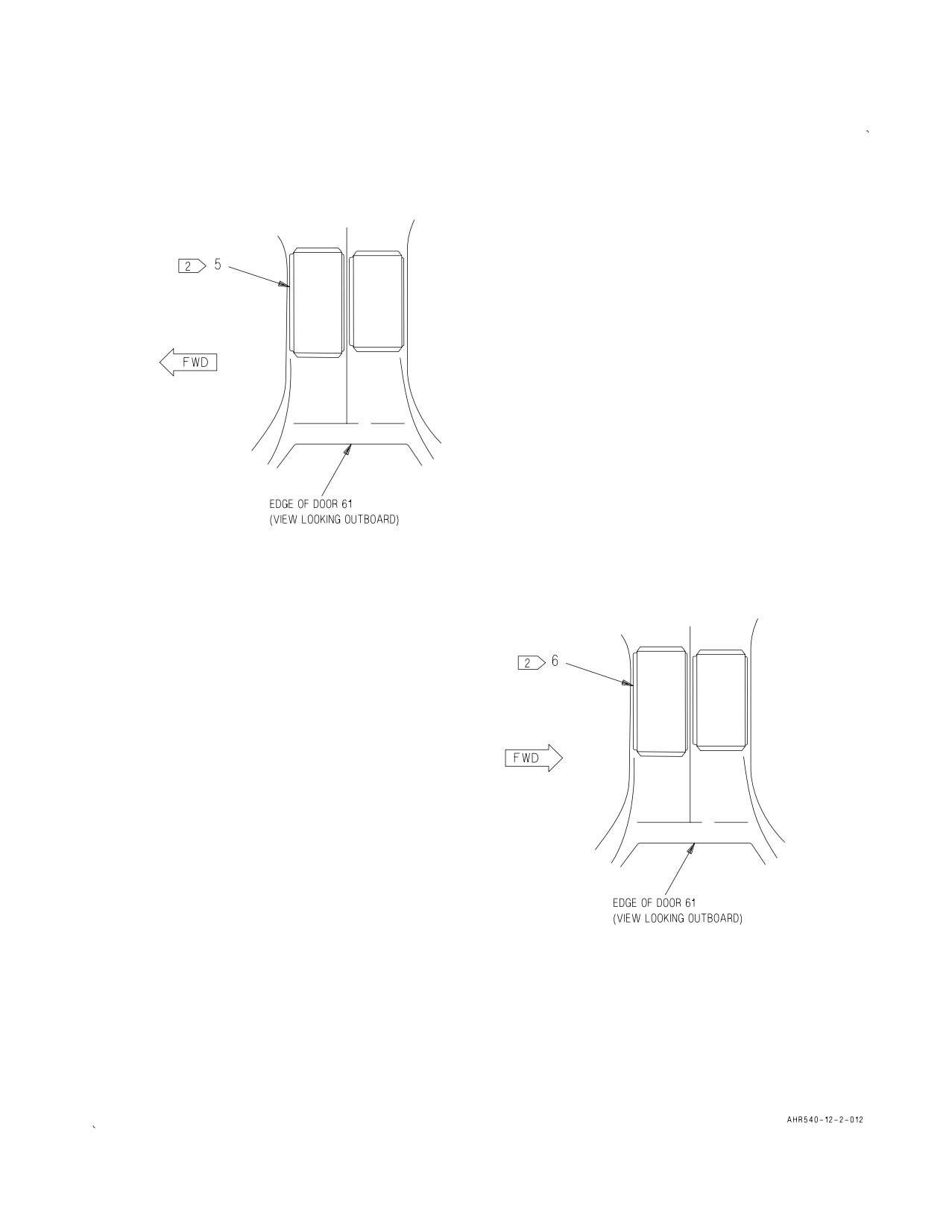
Figure 1. Forward Avionics Cooling System Component Locator (Sheet 2)
A1-AV8BC-410-100
008 00
Change 6
Page 11
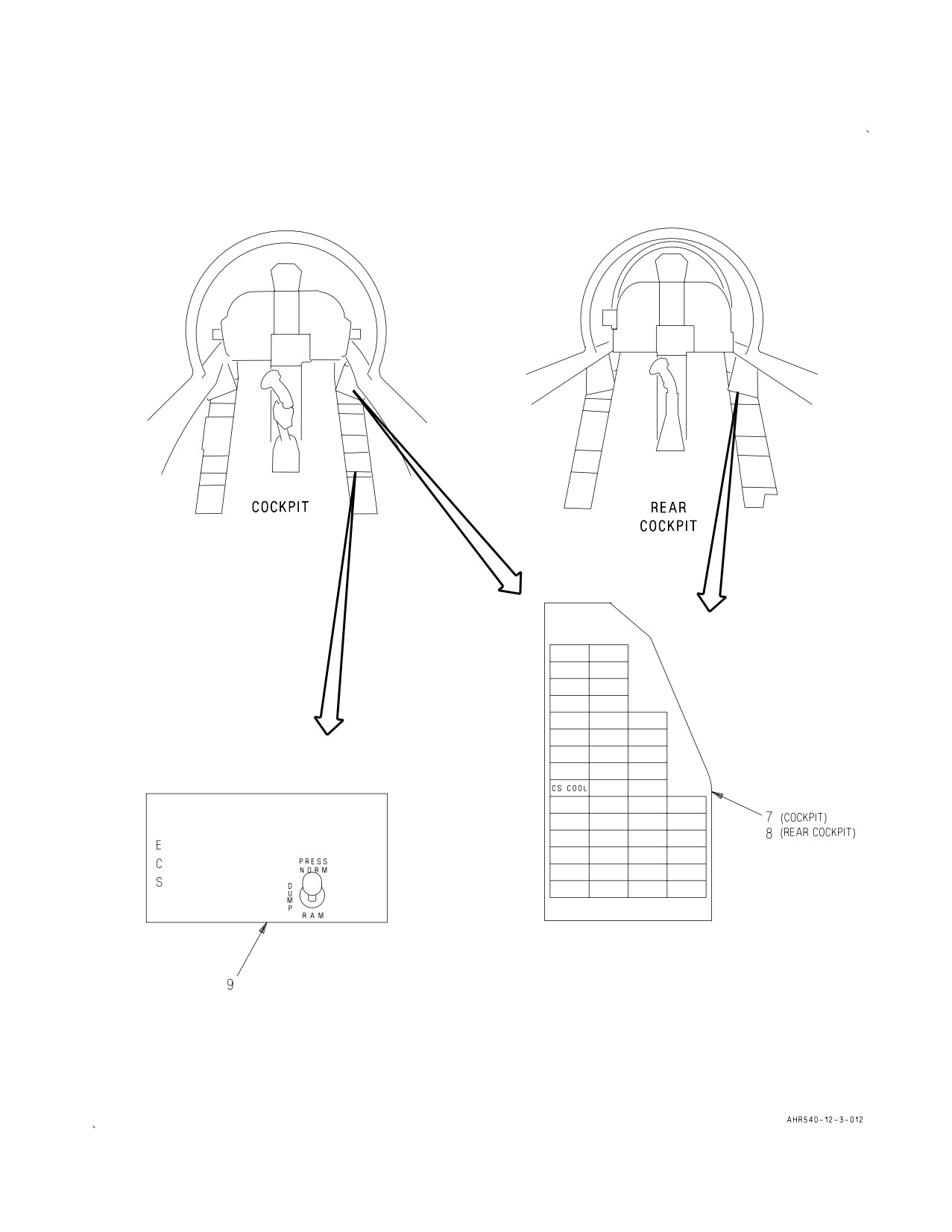
Figure 1. Forward Avionics Cooling System Component Locator (Sheet 3)
A1-AV8BC-410-100
008 00
Change 6
Page 12
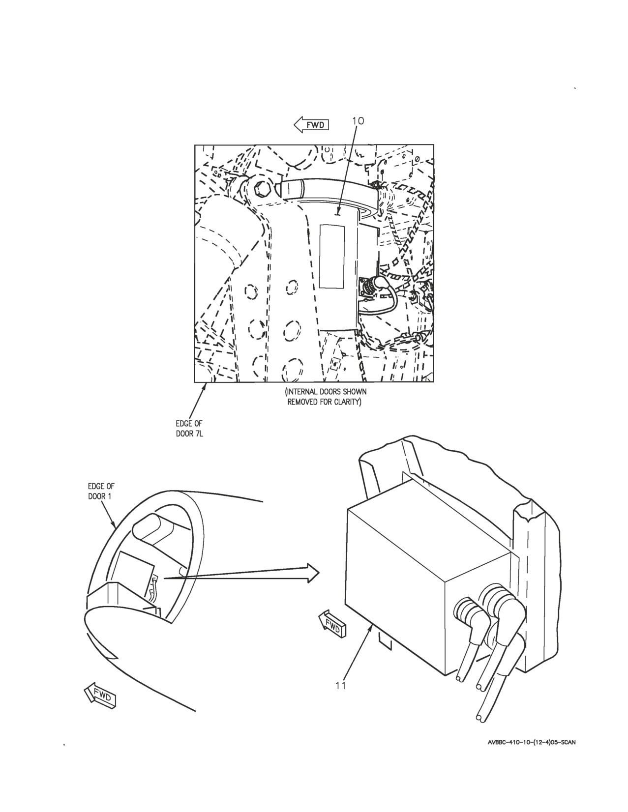
Figure 1. Forward Avionics Cooling System Component Locator (Sheet 4)
A1-AV8BC-410-100
008 00
Change 6
Page 13
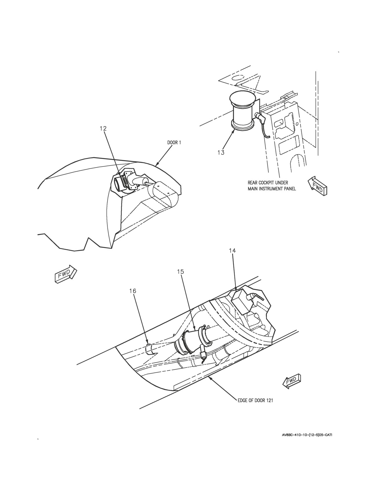
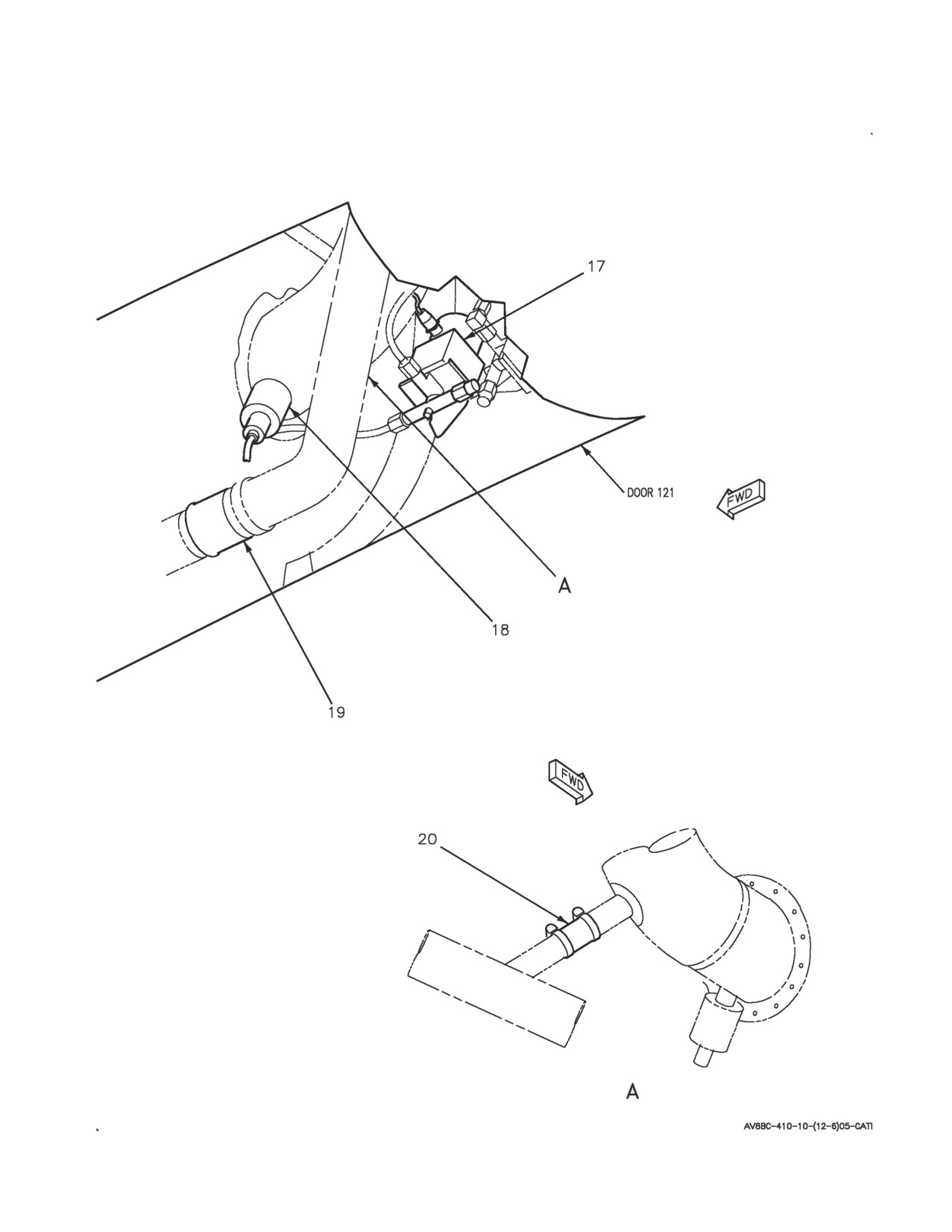
Figure 1. Forward Avionics Cooling System Component Locator (Sheet 5)
A1-AV8BC-410-100
008 00
Change 6
Page 14
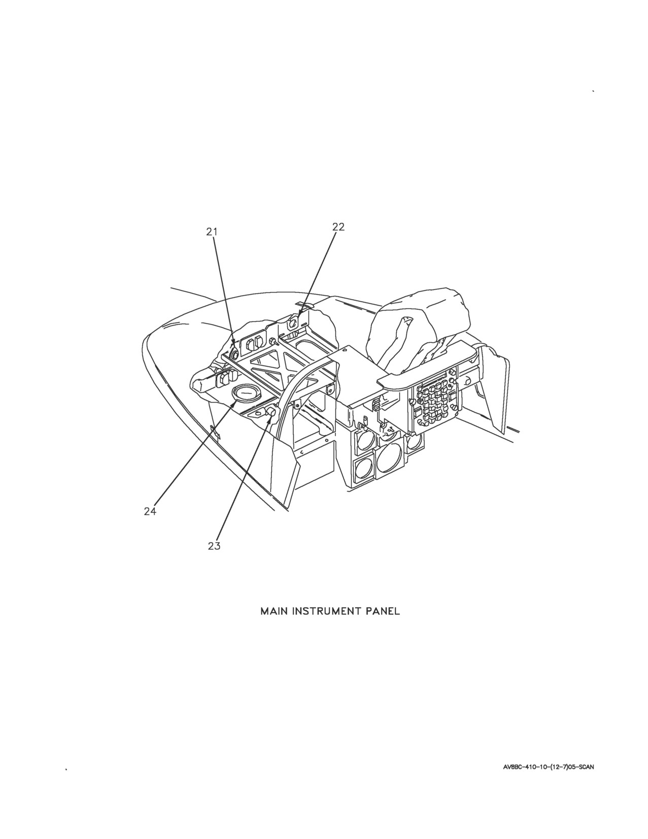
Figure 1. Forward Avionics Cooling System Component Locator (Sheet 6)
A1-AV8BC-410-100
008 00
Change 6
Page 15
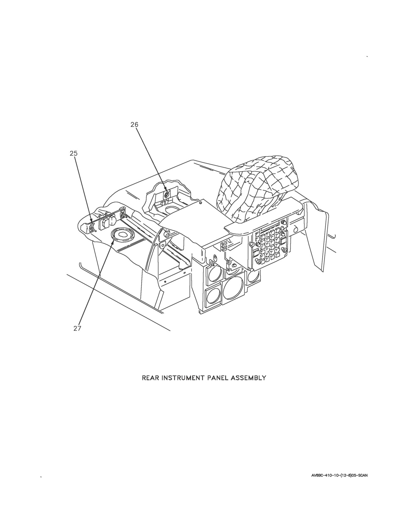
Figure 1. Forward Avionics Cooling System Component Locator (Sheet 7)
A1-AV8BC-410-100
008 00
Change 6
Page 16
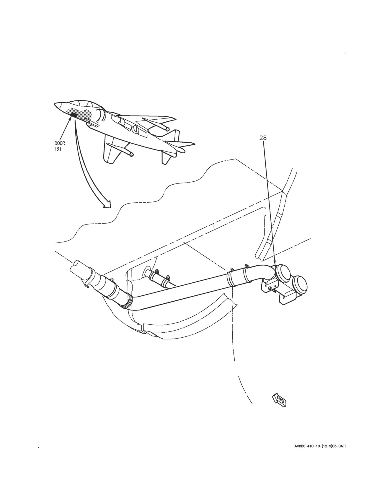
Figure 1. Forward Avionics Cooling System Component Locator (Sheet 8)
A1-AV8BC-410-100
008 00
Change 6
Page 17
Figure 1. Forward Avionics Cooling System Component Locator (Sheet 9)

A1-AV8BC-410-100
008 00
Change
6
Page
18
Nomenclature
Index No.
Ref Des
1
AC CIRCUIT BREAKER PANEL ASSEMBLY
4
52A-C105
FWD FUS FAN A (ZONE A3)
22CBC025
FWD FUS FAN B (ZONE B3)
22CBC026
FWD FUS FAN C (ZONE C3)
22CBC027
AFT CKPT FAN A (ZONE A4)
22CBC061
AFT CKPT FAN B (ZONE B4)
22CBC062
AFT CKPT FAN C (ZONE C4)
22CBC063
FWD CKPT FAN A (ZONE A5)
22CBC035
FWD CKPT FAN B (ZONE B5)
22CBC036
FWD CKPT FAN C (ZONE C5)
22CBC037
2
AC ESSENTIAL PANEL ASSEMBLY
6
52A-N131
FWD FUS COOL FAN (ZONE C6)
22CBN025
FWD FUS COOL FAN (ZONE D6)
22CBN026
FWD FUS COOL FAN (ZONE E6)
22CBN027
CKPT COOL FAN (ZONE C7)
22CBN035
CKPT COOL FAN (ZONE D7)
22CBN036
CKPT COOL FAN (ZONE E7)
22CBN037
AFT CKPT FAN (ZONE C11)
22CBN061
AFT CKPT FAN (ZONE D11)
22CBN062
AFT CKPT FAN (ZONE E11)
22CBN063
ANNUNCIATOR LIGHT CONTROLLER
11
27A-D007
ARMT STORES MANAGEMENT CONTROL -
23
—
INDICATOR C-10940/AYQ-13 COOLING AIR
FITTING
CAUTION/ADVISORY INDICATOR LIGHT
7
27A-F011
ASSEMBLY
COCKPIT AVIONICS COOLING FAN
10
22B-F038
COCKPIT DIFFERENTIAL PRESSURE SWITCH
18
22S-D070
COORDINATE DATA MONITOR ID-2251/ASQ-179
21
—
COOLING AIR FITTING
1
DC CIRCUIT BREAKER PANEL ASSEMBLY
2
52A-C104
CAB ECS NO. 1 (ZONE D7)
22CBC016
CKPT FAN CONT (ZONE E4)
22CBC074
2
DC ESSENTIAL/MAIN PANEL ASSEMBLY
5
52A-P133
CABIN ECS CB NO. 1 (ZONE D4)
22CBP016
CKPT COOL FAN (ZONE E4)
22CBP074
DIGITAL DISPLAY INDICATOR IP-1318/A
24
—
COOLING AIR FITTING
Figure 1. Forward Avionics Cooling System Component Locator (Sheet 10)

A1-AV8BC-410-100
008 00
Change
6
Page
19
Nomenclature
Index No.
Ref Des
ECS CONTROL PANEL ASSEMBLY
9
22A-F048
PRESS SWITCH
22S-F033
FORWARD RELAY NO. 1 PANEL ASSEMBLY
3
52A-C015
GND PWR FAN CONTROL RELAY
22K-C077
COCKPIT COOLING FAN RELAY
22K-C075
REAR COCKPIT COOLING FAN RELAY
22K-C076
ASMCI GND PWR RELAY
1K-C097
FORWARD RELAY NO. 2 PANEL ASSEMBLY
1
52A-C113
20K FT ALT RELAY
70K-C028
FWD FUS COOLING FAN CONTROL RELAY
22K-C028
COCKPIT COOL CANCEL RELAY
22K-C066
WEIGHT ON WHEELS RELAY NO. 1
12K-C053
REAR COCKPIT FAN FAIL RELAY
22K-C064
COCKPIT FAN FAIL RELAY
22K-C065
REAR COCKPIT COOL CANCEL RELAY
22K-C067
FWD FUS FAN FAIL RELAY
22K-C071
GROUND COOLING CONTROL VALVE
17
22L-D040
GROUND COOLING FAN
15
22B-D029
GROUND COOLING VALVE
12
22MAA510
HEAD-UP DISPLAY UNIT SU-128/A COOLING AIR
22
—
FITTING
3
INERTIAL NAVIGATION UNIT CN-1561/ASN-130A
28
—
COOLING PLENUM ASSEMBLY
4
INERTIAL NAVIGATION UNIT CN-1649/ASN-139
28
—
COOLING PLENUM ASSEMBLY
INS CHECK VALVE
19
22VAD528
INS PLENUM CHECK VALVE
20
22VAD529
RAM-AIR VENT CHECK VALVE
16
22VAD527
REAR CAUTION/ADVISORY INDICATOR LIGHT
8
27A-H045
ASSEMBLY
REAR COCKPIT AVIONICS COOLING FAN
13
22B-H072
REAR COORDINATE DATA MONITOR ID-2251/
25
—
ASQ-179 COOLING AIR FITTING
REAR DIGITAL DISPLAY INDICATOR IP-1318/A
27
—
COOLING AIR FITTING
Figure 1. Forward Avionics Cooling System Component Locator (Sheet
11)
A1-AV8BC-410-100
008 00
Change 7
Page 20
Nomenclature
Index No.
Ref Des
REAR HEAD-UP DISPLAY UNIT SU-128/A
26
—
COOLING AIR FITTING
SPEED SENSOR
14
22A-D050
LEGEND
1
162747; ALSO 162963 THRU 163861 BEFORE AV8AFC-416.
2
164113 AND UP; ALSO 162963 THRU 163861 AFTER AV8AFC-416.
3
162747 THRU 164137.
4
164138 AND UP.
Figure 1. Forward Avionics Cooling System Component Locator (Sheet 12)
A1-AV8BC-410-100
008 00
Change 7
Page 21
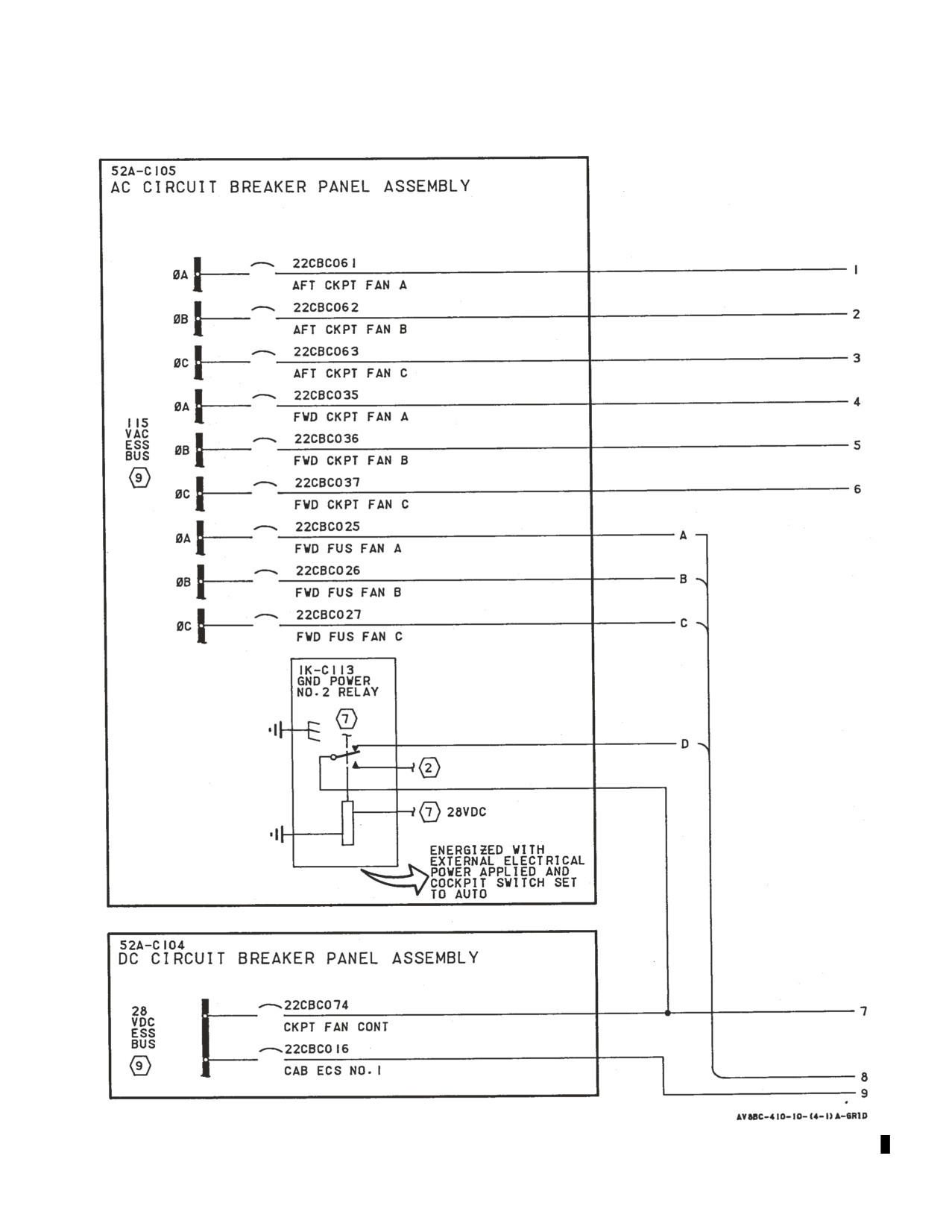
Figure 2. Forward Avionics Cooling System Simplified Schematic-162747; ALSO 162963
THRU 163861 BEFORE AV8AFC-416 (Sheet 1)
A1-AV8BC-410-100
008 00
Change 7
Page 22
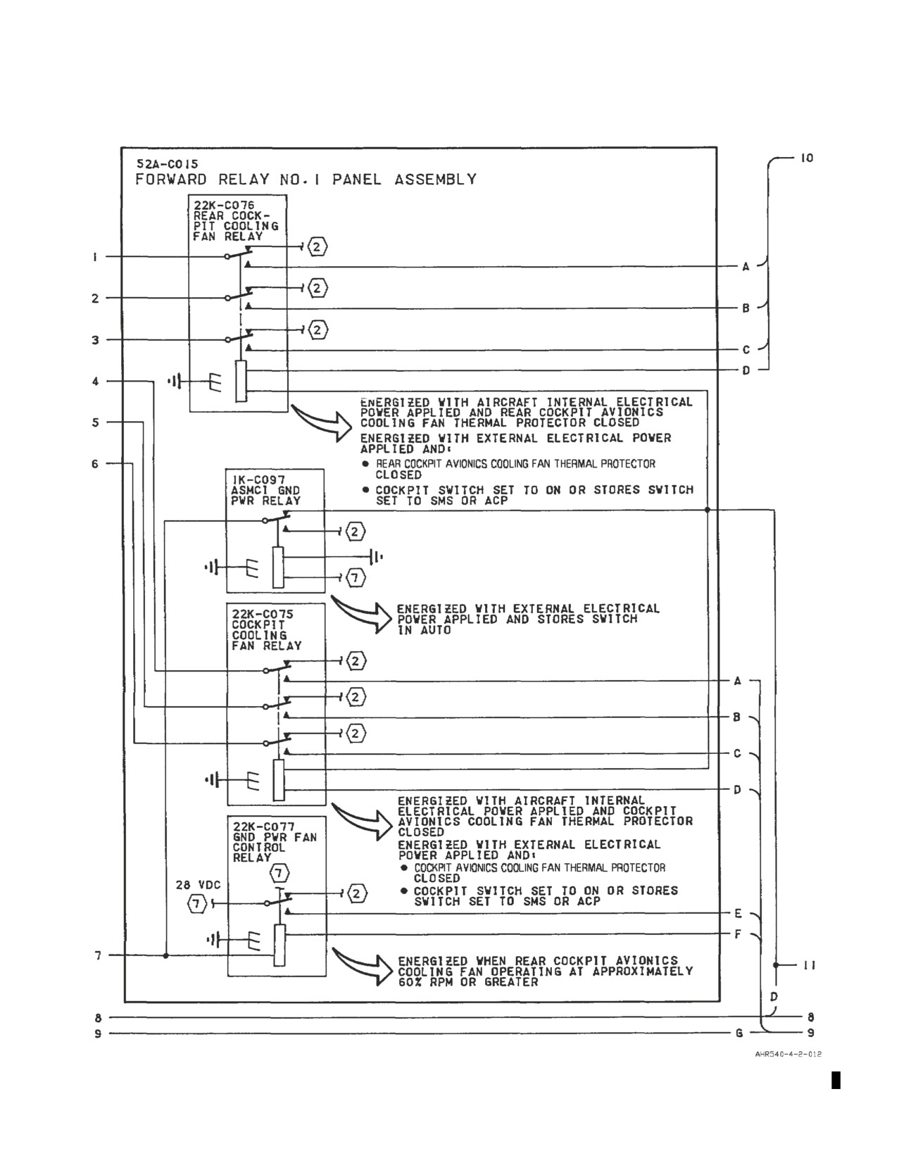
Figure 2. Forward Avionics Cooling System Simplified Schematic-162747; ALSO 162963
THRU 163861 BEFORE AV8AFC-416 (Sheet 2)
A1-AV8BC-410-100
008 00
Change 7
Page 23
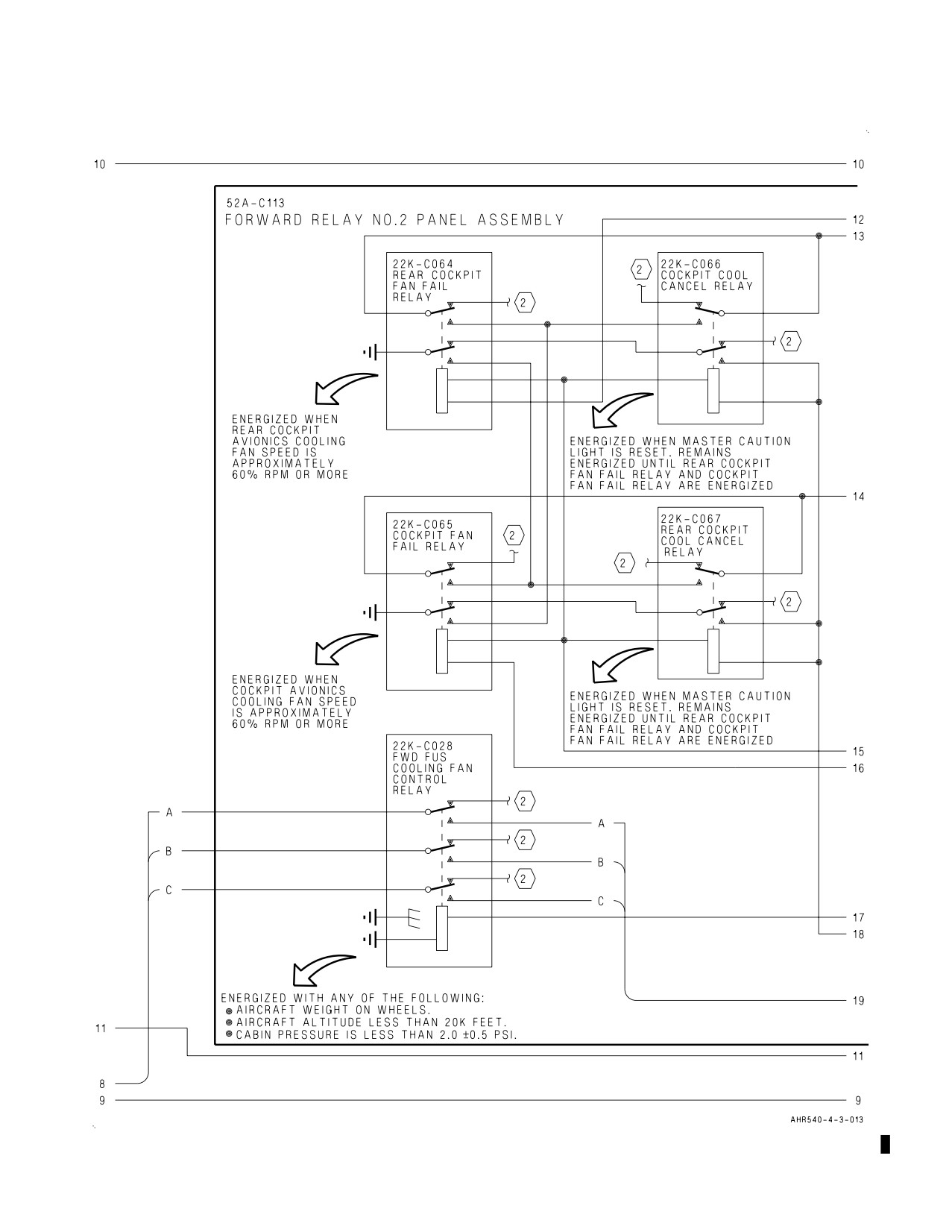
Figure 2. Forward Avionics Cooling System Simplified Schematic-162747; ALSO 162963
THRU 163861 BEFORE AV8AFC-416 (Sheet 3)
A1-AV8BC-410-100
008 00
Change 7
Page 24
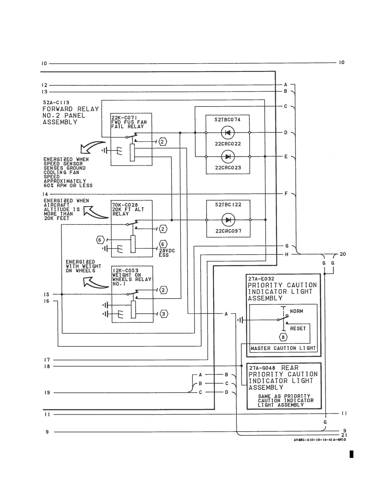
Figure 2. Forward Avionics Cooling System Simplified Schematic-162747; ALSO 162963
THRU 163861 BEFORE AV8AFC-416 (Sheet 4)
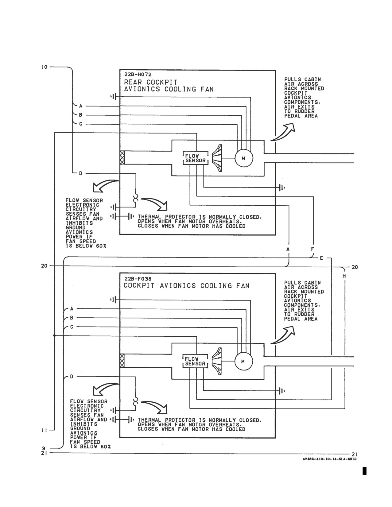
A1-AV8BC-410-100
008 00
Change 7
Page 25
Figure 2. Forward Avionics Cooling System Simplified Schematic-162747; ALSO 162963
THRU 163861 BEFORE AV8AFC-416 (Sheet 5)
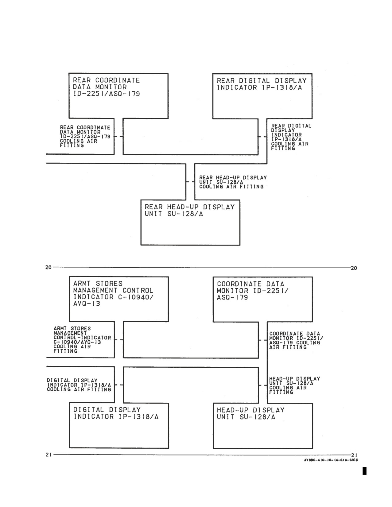
A1-AV8BC-410-100
008 00
Change 7
Page 26
Figure 2. Forward Avionics Cooling System Simplified Schematic-162747; ALSO 162963
THRU 163861 BEFORE AV8AFC-416 (Sheet 6)
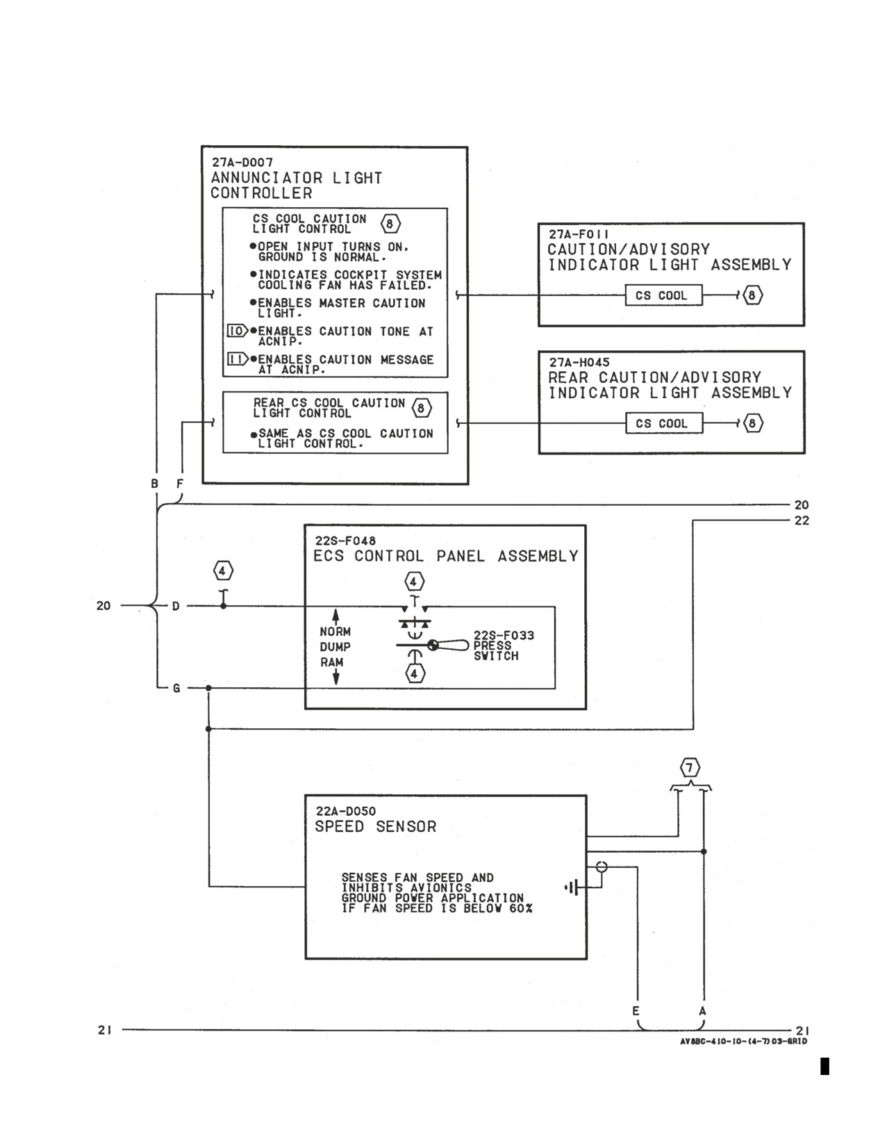
A1-AV8BC-410-100
008 00
Change 7
Page 27
Figure 2. Forward Avionics Cooling System Simplified Schematic-162747; ALSO 162963
THRU 163861 BEFORE AV8AFC-416 (Sheet 7)
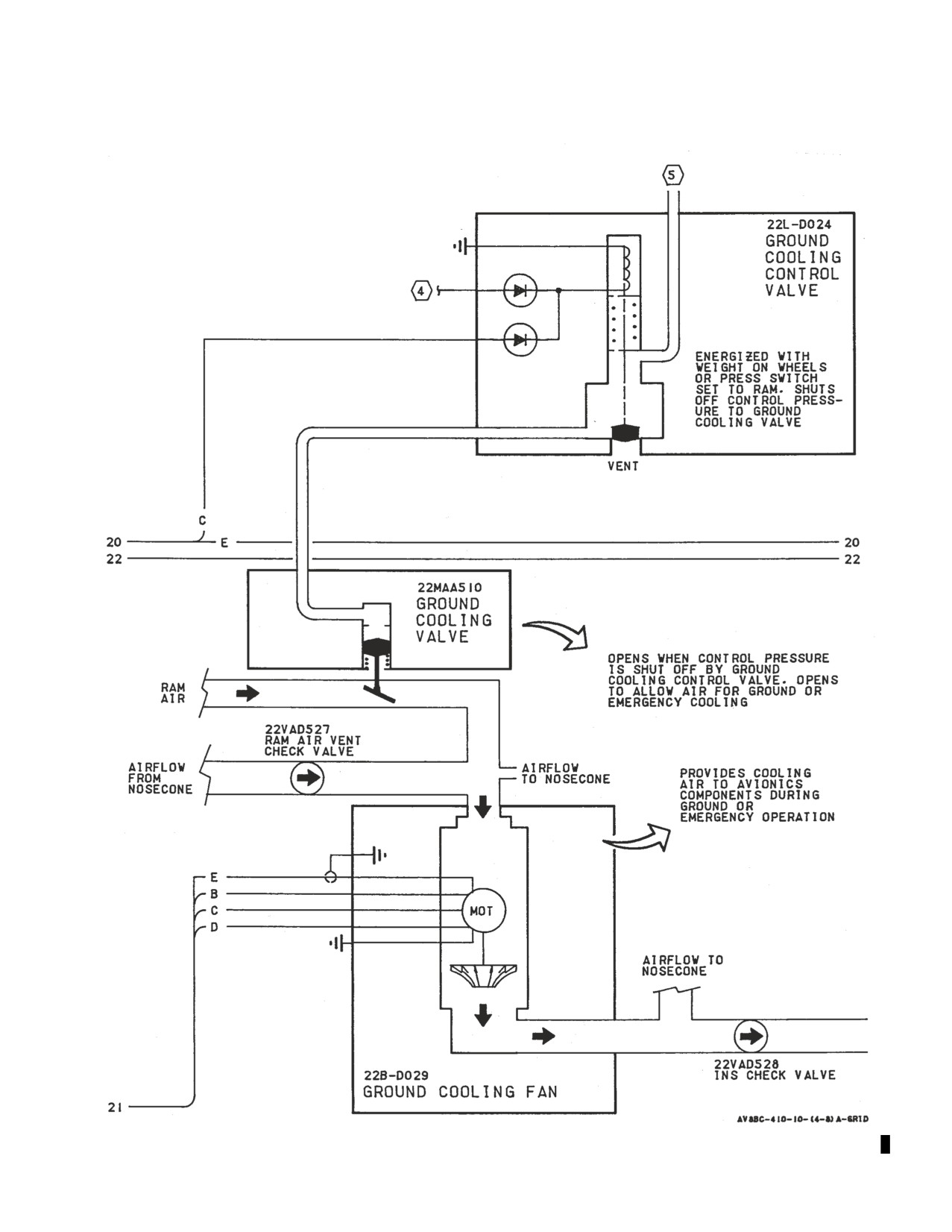
A1-AV8BC-410-100
008 00
Change 7
Page 28
Figure 2. Forward Avionics Cooling System Simplified Schematic-162747; ALSO 162963
THRU 163861 BEFORE AV8AFC-416 (Sheet 8)
A1-AV8BC-410-100
008 00
Change 7
Page 29
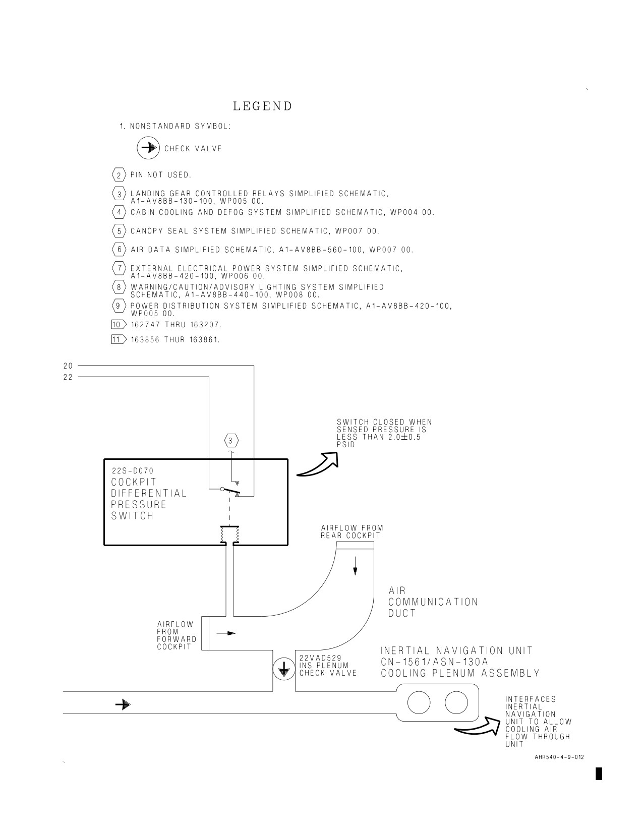
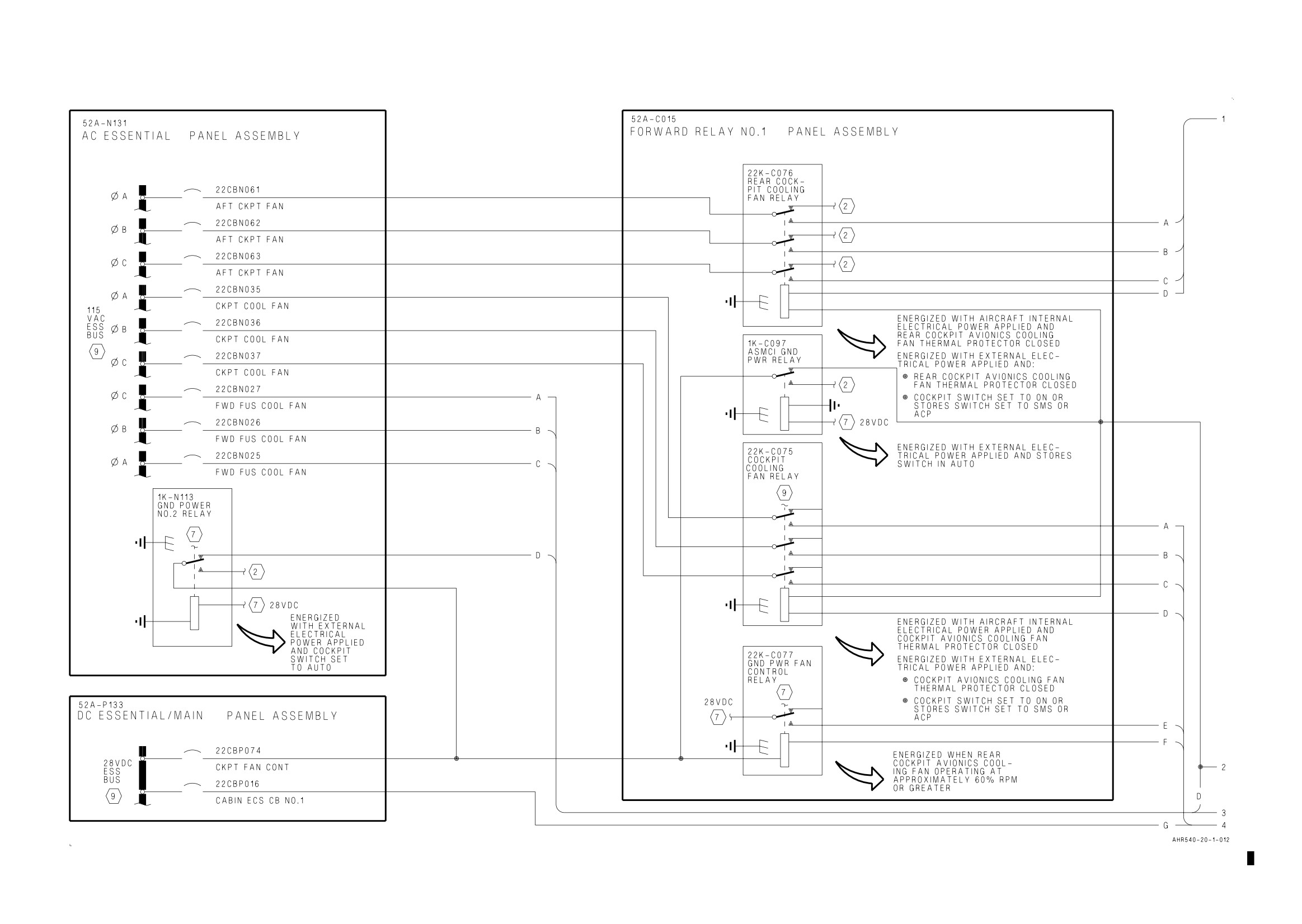
Figure 2. Forward Avionics Cooling System Simplified Schematic-162747; ALSO 162963
THRU 163861 BEFORE AV8AFC-416 (Sheet 9)
A1-AV8BC-410-100
008 00
Change 7
Page 30
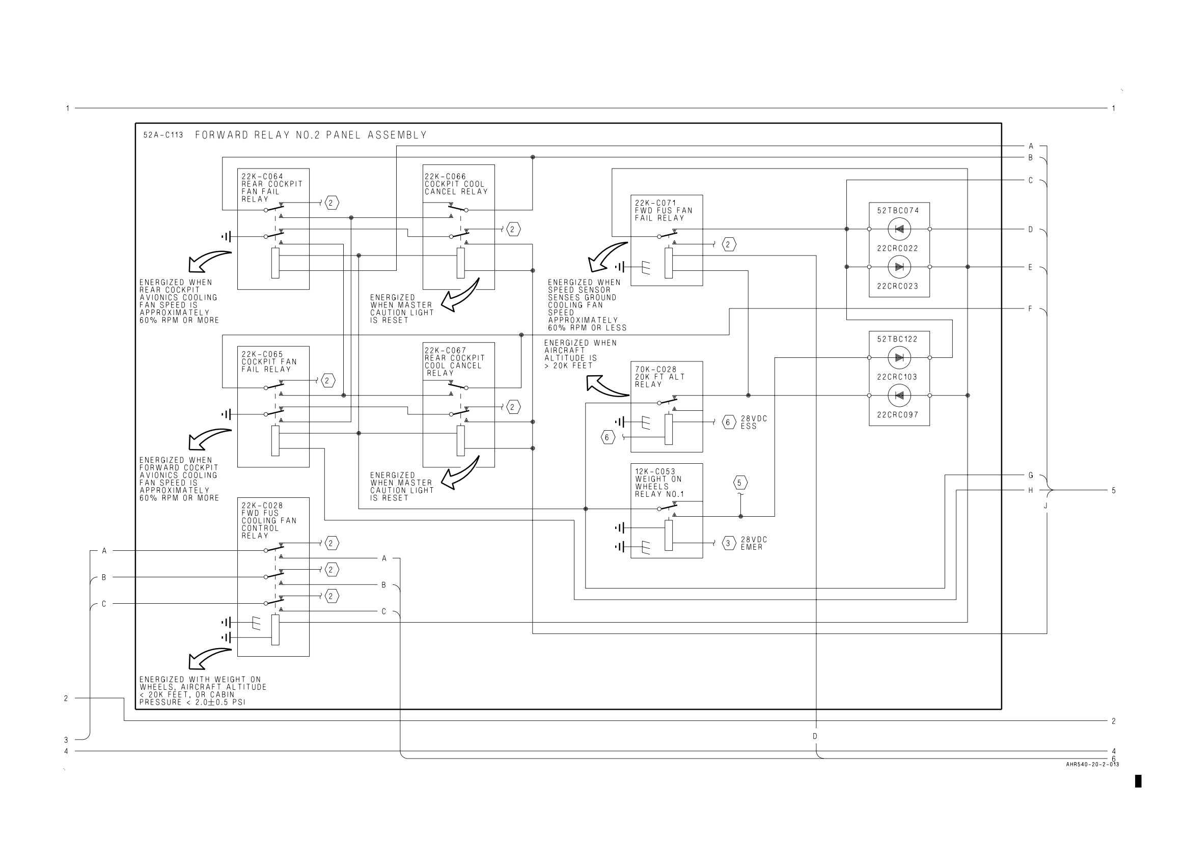
Figure 3. Forward Avionics Cooling System Simplified Schematic-164113 AND UP; ALSO 162963 THRU 163861 AFTER AV8AFC-416 (Sheet 1)
Figure 3.
Figure 3.
A1-AV8BC-410-100
008 00
Change 7
Page 31
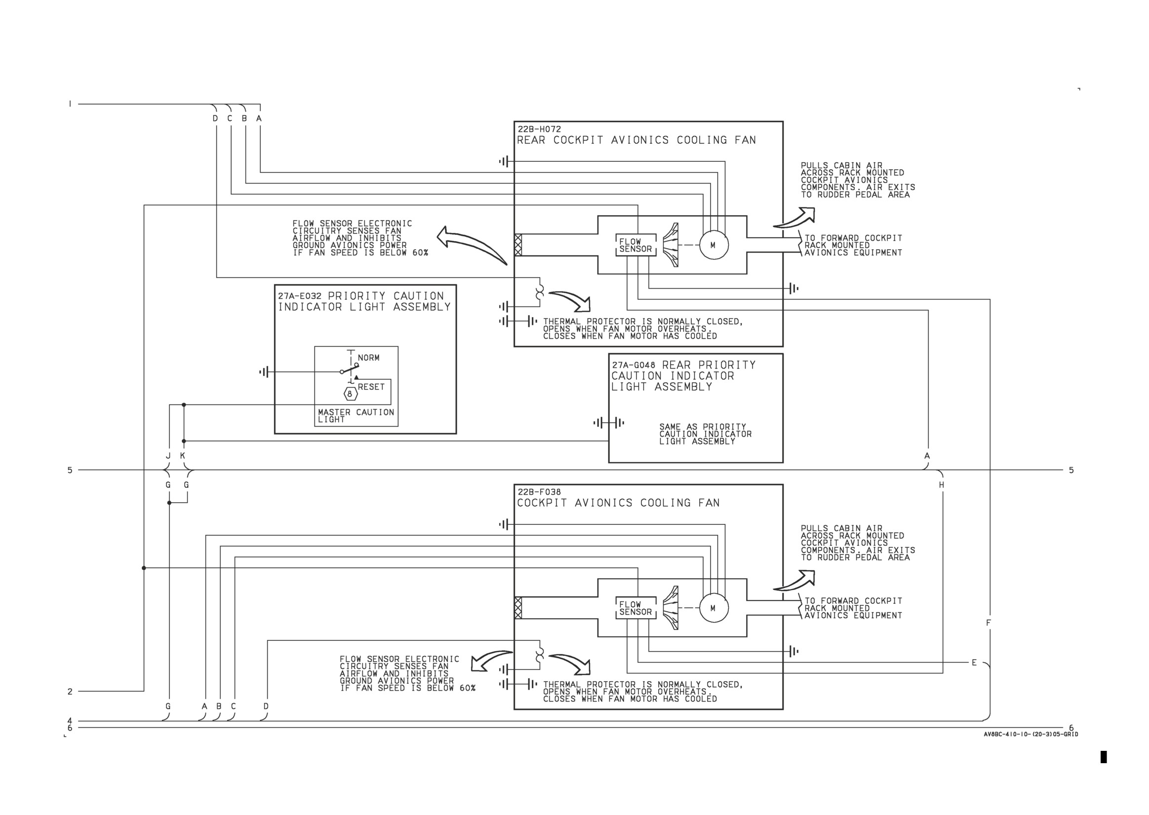
Figure 3. Forward Avionics Cooling System Simplified Schematic-164113 AND UP; ALSO 162963 THRU 163861 AFTER AV8AFC-416 (Sheet 2)
Figure 3.
Figure 3.
A1-AV8BC-410-100
008 00
Change 7
Page 32
Figure 3. Forward Avionics Cooling System Simplified Schematic-164113 AND UP; ALSO 162963 THRU 163861 AFTER AV8AFC-416 (Sheet 3)
Figure 3.
Figure 3.
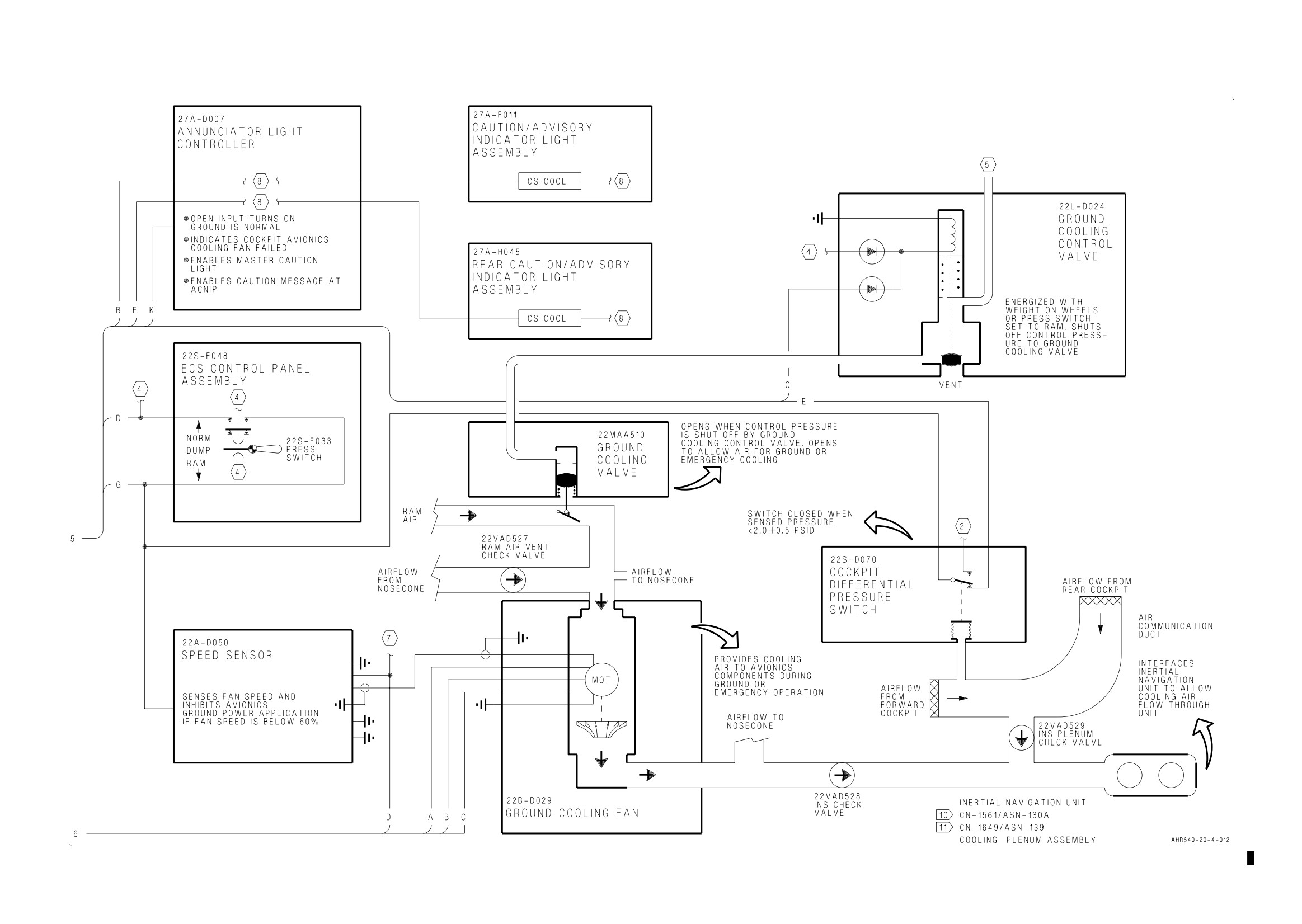
A1-AV8BC-410-100
008 00
Change 7
Page 33
Figure 3. Forward Avionics Cooling System Simplified Schematic-164113 AND UP; ALSO 162963 THRU 163861 AFTER AV8AFC-416 (Sheet 4)
Figure 3.
Figure 3.
A1-AV8BC-410-100
008 00
Change 7
Page 34
Figure 3. Forward Avionics Cooling System Simplified Schematic-164113 AND UP;
ALSO 162963 THRU 163861 AFTER AV8AFC-416 (Sheet 5)
A1-AV8BC-410-100
009 00
1 February 1990
Page 1
ORGANIZATIONAL MAINTENANCE
PRINCIPLES OF OPERATION
ANTI-G SYSTEM
Reference Material
Environmental Control System
A1-AV8BC-410-100
Description and Operation - Cabin Cooling And Defog System
WP004 00
Alphabetical Index
Subject
Page No.
Anti-G System Component Locator, Figure 1
4
Anti-G System Schematic, Figure 2
7
Description
2
Component Description
2
Anti-G/Canopy Seal Check Valve
2
Anti-G/Canopy Seal Test Port
2
Anti-G Disconnect
2
Anti-G Valve
2
Rear Anti-G Disconnect
2
Rear Anti-G Valve
2
Related Systems
2
Cabin Cooling and Defog System
2
System Controls and Indicators
2
Manual Inflation Buttons
2
System Description
2
Operation
2
Component Operation
2
Anti-G/Canopy Seal Check Valve
3
Anti-G/Canopy Seal Test Port
3
Anti-G Disconnect
3
Anti-G Valve
2
Rear Anti-G Disconnect
3
Rear Anti-G Valve
2
System Operation
3
Automatic Mode
3
Ground Test
3
Manual Mode
3
A1-AV8BC-410-100
009 00
Page 2
Record of Applicable Technical Directives
Type/
Date
Title and ECP No.
Date Incorp.
Remarks
Number
AV8AFC-284
-
ANTI-G Valve Replacement (ECP MDC-
15 Oct 88
-
AV-8B-0131C1)
1. DESCRIPTION.
11. Cabin Cooling and Defog System. The cabin
cooling and defog system (WP004 00) provides air
2. SYSTEM DESCRIPTION. The anti-g system
pressure to the anti-g system. Air is tapped from a
automatically regulates air pressure to the
duct between the secondary heat exchanger and the
crewmembers anti-g suits to increase their tolerance
cold air unit expansion turbine inlet.
to high acceleration levels. The anti-g suit reduces
the fatiguing effect of repeated exposure to high
12. SYSTEM CONTROLS AND INDICATORS.
acceleration which can cause grayout or blackout
System controls and indicators are described in
because of lack of oxygen-rich blood to the brain.
paragraphs below.
The anti-g suit applies a regulated pressure to the
crewmembers lower torso to keep oxygen-rich blood
13. Manual Inflation Buttons. The manual
in the upper torso.
inflation buttons on the anti-g valve and rear anti-g
valve allow the crewmembers anti-g suits to be
3. COMPONENT DESCRIPTION. System
manually inflated. All other operation is
components shown in figure 1 are described and
automatically controlled and no indicators are
listed in paragraphs below.
provided.
14. OPERATION.
4. Anti-G Valve. The anti-g valve is a pressure
regulating valve made up of a demand valve, relief
15. COMPONENT OPERATION.
valve, and an activating weight.
16. Anti-G Valve. The anti-g valve is located in the
5. Anti-G Disconnect. The anti-g disconnect is a
pilot services panel assembly. The valve regulates
console mounted quick release disconnect.
air pressure to the crewmembers anti-g suit to no
more than 12 psi. The valve is automatically
6. Anti-G/Canopy Seal Check Valve. The
controlled by G forces on an activating weight in
anti-g/canopy seal check valve is an in line poppet
the valve or manually by pressing the manual
type check valve. The check valve is threaded at
inflation button. In the suit inflation condition, the
each end.
activating weight is pressed down by positive G
force which opens a demand valve allowing air
7. Anti-G/Canopy Seal Test Port. The
pressure to inflate the anti-g suit. When suit
anti-g/canopy seal test port is an in line capped tee
pressure is enough to counteract the G force on the
fitting.
activating weight, the demand valve closes and a
constant suit pressure is held during the G force
8. Rear Anti-G Disconnect. The rear anti-g
condition. When G force is reduced, the activating
disconnect is a console mounted, quick release
disconnect.
weight is moved up by spring tension and suit
pressure is exhausted to the cockpit. This condition
9. Rear Anti-G Valve. The rear anti-g valve is a
is held during suit exhaust and static conditions. A
pressure regulating valve made up of a demand
relief valve prevents anti-g valve outlet pressure
valve, relief valve, and an activating weight.
from exceeding 12 psi.
10. RELATED SYSTEMS. Related systems are
17. Rear Anti-G Valve. The rear anti-g valve is
described in paragraphs below.
located in the rear pilot services panel assembly.
The valve regulates air pressure to the
crewmembers anti-g suit to no more than 12 psi.
The valve is automatically controlled by G forces on
A1-AV8BC-410-100
009 00
Page 3
an activating weight in the valve or manually by
21. Anti-G/Canopy Seal Test Port. The
pressing the manual inflation button. In the suit
anti-g/canopy seal test port is located in the
inflation condition, the activating weight is pressed
forward end of the nose wheelwell. The test port
down by positive G force which opens a demand
allows a ground air source to be used for ground
valve allowing air pressure to inflate the anti-g suit.
testing of the anti-g system.
When suit pressure is enough to counteract the G
force on the activating weight, the demand valve
22. SYSTEM OPERATION.
closes and constant suit pressure is held during the
G force condition. When G force is reduced, the
23. Automatic Mode. Air pressure, tapped from
activating weight is moved up by spring tension and
the cabin cooling and defog system (WP004 00),
suit pressure is exhausted to the rear cockpit. This
passes through the anti-g/canopy seal check valve
condition is held during suit exhaust and static
(figure 2) to the anti-g valves. Positive G forces
conditions. A relief valve prevents anti-g valve
move an activating weight down opening a demand
outlet pressure from exceeding 12 psi.
valve allowing air pressure to inflate the anti-g suit.
When G forces decrease the activating weight is
18. Anti-G Disconnect. The anti-g disconnect,
moved up by spring tension closing the demand
located inboard of the pilot services panel assembly,
valve and opening an exhaust valve, allowing the
provides the quick disconnect interface between the
anti-g suit to deflate.
anti-g system and the crewmembers anti-g suit.
24. Manual Mode. Air pressure, tapped from the
19. Rear Anti-G Disconnect. The rear anti-g
cabin cooling and defog system (WP004 00), passes
disconnect, located inboard of the rear pilot services
through the anti-g/canopy seal check valve (figure
panel assembly, provides the quick disconnect
2) to the anti-g valves. Pressing the manual
interface between the anti-g system and the
inflation button moves an activating weight down
crewmembers anti-g suit.
opening a demand valve allowing air pressure to
inflate the anti-g suit. When the manual inflation
20. Anti-G/Canopy Seal Check Valve. The
button is released, the activating weight is moved
anti-g/canopy seal check valve is a one way check
up by spring tension, closing the demand valve and
valve. The valve is located in the air duct between
opening an exhaust valve, allowing the anti-g suit to
the secondary heat exchanger and the cold air unit
deflate.
expansion turbine inlet. The check valve will
prevent loss of anti-g system pressure if loss of
25. Ground Test. With a ground air source applied,
cabin cooling and defog system (WP004 00)
the anti-g system can be operated manually. The
pressure occurs. The check valve also isolates the
system operation is the same for ground test or
anti-g system so a ground air source can be used.
in-flight manual operation.
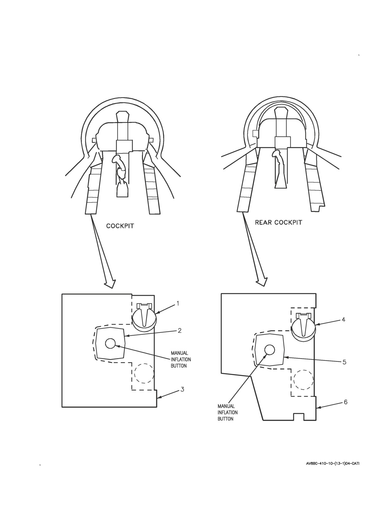
A1-AV8BC-410-100
009 00
Page 4
Figure 1. Anti-G System Component Locator (Sheet 1)
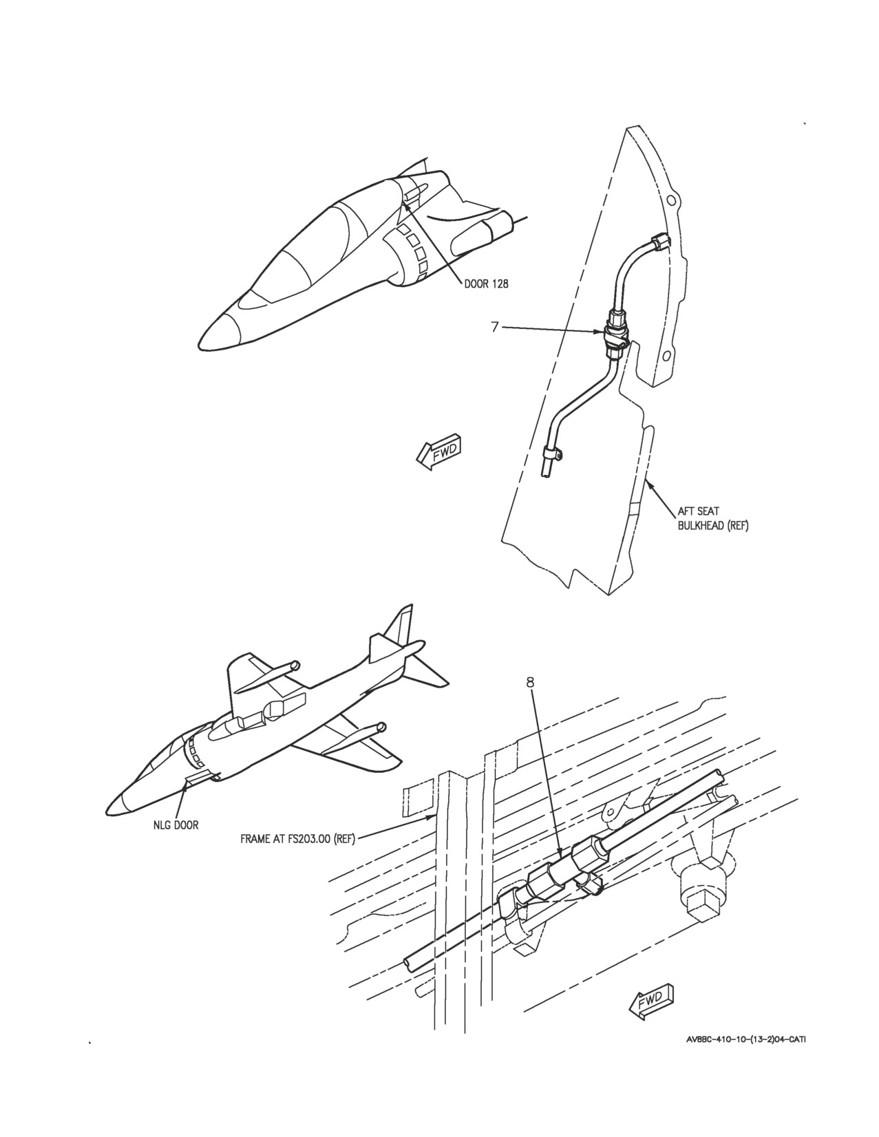
A1-AV8BC-410-100
009 00
Page 5
Figure 1. Anti-G System Component Locator (Sheet 2)

A1-AV8BC-410-100
009 00
Page 6
Nomenclature
Index No.
Ref Des
ANTI-G/CANOPY SEAL CHECK VALVE
7
22VAK516
ANTI-G/CANOPY SEAL TEST PORT
8
—
ANTI-G DISCONNECT
1
—
ANTI-G VALVE
2
22VAE515
PILOT SERVICES PANEL ASSEMBLY
3
52A-E060
REAR ANTI-G DISCONNECT
4
—
REAR ANTI-G VALVE
5
22VAG530
REAR PILOT SERVICES PANEL ASSEMBLY
6
8A-G195
Figure 1. Anti-G System Component Locator (Sheet 3)
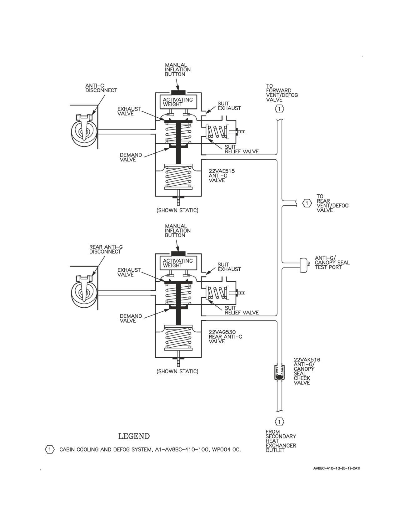
A1-AV8BC-410-100
009 00
Page 7/(8 blank)
Figure 2. Anti-G System Simplified Schematic
A1-AV8BC-410-100
010 00
Change 7 - 15 May 2004
Page 1
ORGANIZATIONAL MAINTENANCE
PRINCIPLES OF OPERATION
REAR EQUIPMENT COOLING SYSTEM
Reference Material
Electrical Systems
A1-AV8BB-420-100
AC Power System
WP003 00
DC Power System
WP004 00
Electrical Systems
A1-AV8BD-420-100
AC Power System
WP003 00
DC Power System
WP004 00
Lighting Systems
A1-AV8BB-440-100
Warning/Caution/Advisory Lighting System
WP007 00
Power Plant and Related Systems
A1-AV8BD-290-100
Basic Engine
WP003 00
Alphabetical Index
Subject
Page No.
Description
2A
Component Description
2A
Avionics Cooling Air Fittings
2A
Rear ECS Air Filter Assembly
2A
Rear ECS Air Inlet Temperature Switch
3
Rear ECS Check Valve
3
Rear ECS Cold Air Unit
3
Rear ECS Cold Air Unit Pressure Switch
3
Rear ECS Ground Cooling Fan
3
Rear ECS Ground Cooling Fan Pressure Switch
3
Rear ECS Ground Cooling Fan Speed Sensor
3
Rear ECS Ground Cooling Valve
3
Rear ECS Heat Exchanger
3
Rear ECS Pressure Reducing and Shutoff Valve
3
Rear ECS Temperature Control Valve
3
Rear ECS Temperature Sensor
3
Related Systems
3
AC Power System
3
DC Power System
3
Power Plant and Related Systems
3
Warning/Caution/Advisory Lighting System
3
System Controls and Indicators
4
AFT BAY Caution Light
4
EQUIP Switch
4
A1-AV8BC-410-100
010 00
Change 7
Page 2
Alphabetical Index (Continued)
Subject
Page No.
Rear Cool Fan Control Relay
4
Rear Equipment Bay Cooling Control Relay
4
60 Sec Delay ECS Relay
4
System Description
2A
Operation
4
Component Operation
4
Avionics Cooling Air Fittings
4
Rear ECS Air Filter Assembly
5
Rear ECS Air Inlet Temperature Switch
5
Rear ECS Check Valve
5
Rear ECS Cold Air Unit
5
Rear ECS Cold Air Unit Pressure Switch
5
Rear ECS Ground Cooling Fan
5
Rear ECS Ground Cooling Fan Pressure Switch
6
Rear ECS Ground Cooling Fan Speed Sensor
6
Rear ECS Ground Cooling Valve
6
Rear ECS Heat Exchanger
6
Rear ECS Pressure Reducing and Shutoff Valve
6
Rear ECS Temperature Control Valve
7
Rear ECS Temperature Sensor
6
System Operation
7
Emergency/Ground Operation
7
Normal Operation
7
Rear Equipment Cooling System Component Locator, Figure 1
8
Rear Equipment Cooling System Simplified Schematic-162747; ALSO 162963 THRU 163861
BEFORE AV8AFC-416, Figure 2
20
Rear Equipment Cooling System Simplified Schematic-164113 AND UP; ALSO 162963 THRU
163861 AFTER AV8AFC-416, Figure 3
24
Record of Applicable Technical Directives
Type/
Date
Date
Title and ECP or RAMEC No.
Remarks
Number
Incorp.
AV8AFC-354
30 Jun 94
Global Positioning System (GPS) Provisions
1 Mar 97
—
and Mini TACAN Incorporation of (ECP
MDC-AV8-0168C1)
AV8AFC-393
3 Sep 99
Addition of Digital Flap Controller (DFC)
15 May 99
—
(ECP MDC-AV8-00255R1)
AV8AFC-416
— TAV-8B Polyimide Wire Replacement/
15 May 04
—
Power Wire Separation (ECP MDA-AV8B-
0277)
A1-AV8BC-410-100
010 00
Change 6
Page 2A/(2B blank)
1.
DESCRIPTION.
4. Avionics Cooling Air Fittings. Several different
types of fittings are used. Cooling requirements and
2. SYSTEM DESCRIPTION. Aft fuselage mounted
mounting provisions vary for different avionics
avionics equipment is cooled by the rear equipment
units. Some fittings are collapsible, self sealing
cooling system. Engine bleed air, extracted from the
assemblies. Others are duct flanges. Fittings may or
sixth stage of compression, is conditioned and
may not include filters and/or orifices.
distributed to the rack mounted avionics equipment
to provide required cooling.
5. Rear ECS Air Filter Assembly. The rear ECS air
filter assembly is a reusable, steel mesh filter
3. COMPONENT DESCRIPTION. System
element encased in a housing with a spring loaded
components shown in figure 1 are described and
bypass valve.
listed in paragraphs below.
A1-AV8BC-410-100
010 00
Change 7
Page 3
6. Rear ECS Air Inlet Temperature Switch. The
regulating section and shutoff valve section are
rear ECS air inlet temperature switch is a
made up of a piston sliding within a cylinder on a
temperature sensitive switch encased in a threaded
hollow shaft. The shutoff valve section piston is
housing.
spring loaded closed and the pressure regulating
section piston is spring loaded open. The pressure
7. Rear ECS Check Valve. The rear ECS check
regulating section also has a blowoff valve.
valve is a flapper type, in line, spring loaded closed,
check valve.
16. Rear ECS Temperature Sensor. The rear ECS
temperature sensor is a temperature sensitive
8. Rear ECS Cold Air Unit. The rear ECS cold air
control device made up of a body, a bimetallic
unit is an expansion turbine and axial flow fan,
temperature sensitive strip with a valve seat
mounted at opposite ends of a common shaft, in a
connected to one end, and an orifice adapter.
common housing. The unit has a serviceable bearing
lubrication system and a bearing cooling system.
17. Rear ECS Temperature Control Valve. The
rear ECS temperature control valve is a
9. Rear ECS Cold Air Unit Pressure Switch. The
pneumatically controlled and actuated flow control
rear ECS cold air unit pressure switch is a pressure
valve. The valve is made up of a body enclosing a
sensitive electrical switch encased in a threaded
spring-loaded double-action piston and hollow shaft
housing.
attached to a poppet valve and an orifice filter. The
valve is spring loaded closed.
10. Rear ECS Ground Cooling Fan. The rear ECS
ground cooling fan is an electrically driven axial
18. RELATED SYSTEMS. Related systems are
flow fan. The fan is made up of a flow impeller
described in paragraphs below.
mounted directly to the shaft of a 3 phase, 400 Hz
electrical motor. The motor and impeller are
19. Power Plant and Related Systems. Hot, high
enclosed in a housing with guide vanes built in on
pressure bleed air is provided by the engine sixth
the outlet end of the impeller. The motor has an
stage compressor (A1-AV8BD-290-100, WP003 00).
electrical sensing unit and overheat protection
devices.
20. DC Power System. The DC power system on
162747; ALSO 162963 THRU 163861 BEFORE
11. Rear ECS Ground Cooling Fan Pressure
AV8AFC-416 (A1-AV8BB-420-100, WP004 00) or
Switch. The rear ECS ground cooling fan pressure
164113 AND UP; ALSO 162963 THRU 163861
switch is a pressure sensitive electrical switch
AFTER AV8AFC-416 (A1-AV8BD-420-100, WP004
encased in a threaded housing.
00) provides 28vdc essential power for the rear
equipment cooling system.
12. Rear ECS Ground Cooling Fan Speed Sensor.
The rear ECS ground cooling fan speed sensor is an
21. AC Power System. The AC power system on
electronic processing unit in a sealed case.
162747; ALSO 162963 THRU 163861 BEFORE
AV8AFC-416 (A1-AV8BB-420-100, WP003 00) or
13. Rear ECS Ground Cooling Valve. The rear
164113 AND UP; ALSO 162963 THRU 163861
ECS ground cooling valve is a two position
AFTER AV8AFC-416 (A1-AV8BD-420-100, WP003
pneumatically actuated and controlled valve. The
00) provides essential 115vac for the rear equipment
valve is made up of a housing which contains a
cooling system.
piston attached to a spring loaded diaphragm that
controls a hinged valve.
22. Warning/Caution/Advisory Lighting System.
The warning/caution/advisory lighting system
14. Rear ECS Heat Exchanger. The rear ECS heat
(A1-AV8BB-440-100, WP007 00) provides visual
exchanger is a single pass, cross flow, air to air heat
indication of normal aircraft functions and system
exchanger. The heat exchanger is made up of a
malfunctions affecting safety of flight operations.
finned core inside a welded housing.
The warning/caution/advisory lighting system
includes the annunciator light controller and the
15. Rear ECS Pressure Reducing and Shutoff
caution/advisory indicator light assembly. The
Valve. The rear ECS pressure reducing and shutoff
annunciator light controller receives data from
valve is a solenoid controlled pressure regulating
various aircraft systems and provides logic to turn
and shutoff valve in a single unit. Both the pressure
on and off warning/caution/advisory lights.
A1-AV8BC-410-100
010 00
Page 4
23. The annunciator light controller will turn on
deenergized, essential 115vac is applied to the rear
the AFT BAY caution lights and the MASTER
ECS ground cooling fan.
CAUTION lights when the rear equipment cooling
system is off.
33. Rear Equipment Bay Cooling Control Relay.
The rear equipment bay cooling control relay,
24. SYSTEM CONTROLS AND INDICATORS.
located on the distribution panel assembly, is a dual
System controls and indicators are described in
pole, double throw, 5 amperes, permanent magnet
paragraphs below.
drive, armature relay.
25. EQUIP Switch. The EQUIP switch, located on
34. The relay is controlled by the rear ECS air inlet
the ECS control panel assembly, is a dual pole
temperature switch or the rear ECS cold air unit
toggle switch. The switch provides electrical control
pressure unit switch. With the relay energized, the
for the rear ECS pressure reducing and shutoff
following occurs:
valve. The switch has three positions: RESET, ON,
and OFF. The switch must be held in RESET.
a. Essential 28vdc power is applied to energize
the rear ECS pressure reducing and shutoff valve
26. Setting the EQUIP switch to ON applies
solenoid.
essential 28vdc power to contacts of the rear
equipment bay cooling control relay.
b. Essential 28vdc power is removed from the
annunciator light controller to enable the AFT BAY
27. Setting the EQUIP switch to OFF applies
caution lights.
essential 28vdc power to a contact of the rear
equipment bay cooling control relay and energizes
35. With the relay deenergized, the following
the rear ECS pressure reducing and shutoff valve
occurs:
solenoid. Energizing the solenoid closes the valve.
Power applied to rear equipment bay cooling
a. Essential 28vdc power is removed to
control relay contacts with the EQUIP switch ON is
deenergize the rear ECS pressure reducing and
removed with the EQUIP switch OFF.
shutoff valve solenoid.
28. Setting and holding the EQUIP switch to
b. Essential 28vdc power is applied to the
RESET removes essential 28vdc power from the
annunciator light controller to disable the AFT
rear equipment bay cooling control relay contact
BAY caution lights.
and from the rear ECS pressure reducing and
shutoff valve solenoid, opening the valve.
36. 60 Sec Delay ECS Relay. The 60 sec delay ECS
relay, located on the aft relay panel assembly is a
29. AFT BAY Caution Lights. The AFT BAY
time delay, 10 amperes, dual pole, double throw,
caution lights, located on the caution/advisory
armature. The relay contacts move 60 seconds after
indicator light assembly and the rear
the relay is energized. When deenergized, the
caution/advisory indicator light assembly are yellow
contacts move immediately.
lens, dual lamp, indicator lights.
37. The relay is controlled by the rear ECS cold air
30. The AFT BAY caution lights are controlled by
unit pressure switch. With the relay energized,
the rear ECS air inlet temperature switch, or the
essential 28vdc power is applied to the input of the
rear ECS cold air unit pressure switch, through the
rear ECS air inlet temperature switch. With the
warning/caution/ advisory lighting system.
relay deenergized, essential 28vdc power is removed
from the input of the rear ECS air inlet
31. Rear Cool Fan Control Relay. The rear cool fan
temperature switch.
control relay, located on the distribution panel
assembly, is a four pole, double throw, 5 amperes,
38. OPERATION.
permanent magnet drive, armature relay.
39. COMPONENT OPERATION.
32. The relay is controlled by the rear ECS ground
cooling fan pressure switch. With the relay
40. Avionics Cooling Air Fittings. Avionics cooling
energized, essential 115vac is removed from the rear
air fittings, located on the equipment cooling rack,
ECS ground cooling fan. With the relay
provide the cooling system interface between rack
A1-AV8BC-410-100
010 00
Page 5
mounted equipment and the equipment rack. When
and sent by way of ducting to mix with hot air from
a unit is installed on the equipment rack, it makes
the rear ECS temperature control valve.
contact with a cooling air fitting. The fitting makes
a seal between the unit and the rack, allowing
45. During ground operation, the driven axial flow
cooling air to flow through the unit. Some fittings
fan draws ram air across the rear ECS heat
contact the unit on the back and some contact the
exchanger. The ram air then exits through the ram
bottom, depending on unit mounting. The different
air exhaust.
types of fittings used are required for the different
cooling requirements of each unit.
46. Lubrication for the common shaft is provided
41. Rear ECS Air Filter Assembly. The rear ECS
by oil stored in a cotton wool pack sump and
air filter element assembly is located in the MLG
transported to the shaft by a system of oil wicks.
wheelwell. Sixth stage engine bleed air is sent by
The sump has fill and drain plugs located to allow
way of ducting to the filter assembly. The filter
periodic servicing of oil while the unit is still in the
removes particulate contamination before it can
aircraft.
cause damage further downstream in the rear
equipment cooling system. If the filter element
47. Shaft bearing cooling is provided by a tube,
becomes blocked, pressure build up opens a bypass
tapped into the ram air inlet, which transports
valve allowing air to bypass the filter element. The
cooling air to the shaft bearings.
bypass valve opens at 4 psid. The filter element is
replaceable independent of the housing or may be
48. Rear ECS Cold Air Unit Pressure Switch. The
cleaned and reused. With the element removed, the
rear ECS cold air unit pressure switch is located in
housing allows a ground air source to be adapted
the rear ECS cold air unit expansion turbine inlet
and used for ground operational checkout.
duct. When turbine inlet pressure exceeds 72 psi,
the pressure switch closes and applies essential
42. Rear ECS Air Inlet Temperature Switch. The
28vdc to energize the rear equipment bay cooling
rear ECS air inlet temperature switch is located in
control relay. When turbine inlet pressure decreases
the equipment cooling shelf supply duct. If
to below 72 psi, the switch opens to enable the rear
equipment cooling air exceeds 131°F, the
equipment bay cooling control relay to be manually
temperature switch closes and applies essential
reset. After an overpressure occurs, the system must
28vdc to energize the rear equipment bay cooling
be manually reset, using the EQUIP switch located
control relay. When equipment cooling air decreases
on the ECS control panel assembly.
to less than 130°F, the temperature switch opens to
enable the rear equipment bay cooling control relay
49. Rear ECS Ground Cooling Fan. The rear ECS
to be manually reset. After an overheat occurs, the
ground cooling fan is located in a duct tapped from
system must be manually reset, using the EQUIP
the rear ECS ram air inlet in door 61. With the fan
switch located on the ECS control panel assembly.
operating, air is pulled in through the rear ECS ram
air inlet. The cooling air is given a high velocity by
43. Rear ECS Check Valve. The rear ECS check
the fan impeller and is transported by way of
valve is located in the left hand rear equipment
ducting to the equipment cooling rack. The fan will
cooling system exhaust duct. The check valve
operate when electrical power is applied and rear
prevents reverse airflow from being induced into the
equipment cooling system pressure is less than 5.0
system during ground operation. The check valve
psi.
also prevents the ingestion of foreign objects into
the system.
50. The guide vanes straighten the airflow before
44. Rear ECS Cold Air Unit. The rear ECS cold air
discharge from the fan. The electrical sensing unit
unit is located at the base of the rear ECS heat
provides an electrical signal to the rear ECS ground
exchanger in door 61. The expansion turbine
cooling fan speed sensor based on fan speed. The
receives pre-cooled air from the rear ECS heat
overheat protection devices will automatically stop
exchanger. Heat energy is converted to mechanical
the fan, if an overheat condition occurs. When the
energy by spinning the expansion turbine. The
overheat condition no longer exists, the fan will
turbine drives the axial flow fan through the
resume normal operation. The fan motor is cooled
common shaft. With the heat lost, cold air is left
by its own airflow.
A1-AV8BC-410-100
010 00
Page 6
51. Rear ECS Ground Cooling Fan Pressure
duct in door 61. The heat exchanger initially cools
Switch. The rear ECS ground cooling fan pressure
sixth stage engine bleed air for use in the rear
switch is located in the rear ECS heat exchanger
equipment cooling system. The engine bleed air
outlet duct in door 61. When system pressure is
enters the heat exchanger core and is cooled by ram
greater than 5.0 psi the switch does the following:
air forced across the core by aircraft forward
motion. During ground operation, ram air is pulled
a. Applies essential 28vdc to energize the rear
across the core by the axial flow fan of the rear ECS
cooling fan control relay.
cold air unit. The partly cooled bleed air is then
sent to the turbine section of the rear ECS cold air
b. Applies essential 28vdc to disable the AFT
unit. In the heat exchanger core, the engine bleed
BAY caution lights.
air makes two passes, the cooling air makes only
one pass.
c. Removes essential 28vdc from the rear ECS
ground cooling fan speed sensor. When system
55. Rear ECS Pressure Reducing And Shutoff
pressure is less than 5.0 psi, the switch does the
Valve. The rear ECS pressure reducing and shutoff
following:
valve is located in the engine bleed air supply duct,
in the MLG wheelwell. The valve assembly encloses
d. Removes essential 28vdc to deenergize the
a small solenoid operated valve and provides a
rear cooling fan control relay.
flange for the attachment of the valve solenoid. The
solenoid is energized by essential 28vdc to close the
e. Applies essential 28vdc to the rear ECS
valve and deenergized to open the valve. This valve,
ground cooling fan speed sensor.
which is spring loaded, controls two ports, one
opening to atmosphere and the other to system
f. Removes essential 28vdc to enable the AFT
pressure; the spring keeps the port to atmosphere
BAY caution lights.
open and the other port shut. The body also
52. Rear ECS Ground Cooling Fan Speed Sensor.
encloses the assembly which controls the shutoff
The rear ECS ground cooling fan speed sensor is
and regulating functions, and also has a safety
located on the left side of the rear equipment bay in
valve, inlet and outlet connection. The shutoff valve
door 61. The speed sensor receives an electrical
is spring loaded and free to slide over a fixed
signal from the rear ECS ground cooling fan
cylinder located by a hollow shaft. This shaft carries
electronic sensing unit. The signal is proportional to
a collar over which slides a spring loaded sleeve,
fan rotational speed. If the signal received by the
which controls the regulating function by varying
speed sensor is within a predetermined limit, the
the size of the annular port based on the system
speed sensor will complete an electrical circuit and
demand. Various drillings in the assembly allows
allow avionics ground power to be applied. If the
atmospheric pressure or system pressure to enter
signal is out of limits, the speed sensor will inhibit
the space between the shutoff valve and the
application of power to the avionics equipment.
cylinder (depending on the position of the
controlling valve) and system pressure only to the
53. Rear ECS Ground Cooling Valve. The rear
rest of the assembly.
ECS ground cooling valve is located on the rear
ECS ram air inlet duct in door 61. When air
56. If an electrical system failure occurs, the rear
pressure is applied to the valve (rear equipment
ECS pressure reducing and shutoff valve will move
cooling system operating normally), the spring
to the open (deenergized) position.
loaded diaphragm is compressed and the valve is
held closed. When air pressure is lost (rear
57. Rear ECS Temperature Sensor. The rear ECS
equipment cooling system shutdown), the spring
temperature sensor is located in the equipment
force moves the piston to open the valve. The valve,
cooling supply duct, in door 61. The sensor senses
with the rear ECS ground cooling fan, allows
air temperature and adjusts the rear ECS
ambient air to flow and cool aircraft equipment for
temperature control valve to provide the required
ground operation and inflight if a cooling system
temperature. The sensor bi-metal strip is connected
failure occurs.
to the inside of the sensor body so the valve seat
fits centrally on the face of the orifice adapter. The
54. Rear ECS Heat Exchanger. The rear ECS heat
orifice adapter is connected to an air connection of
exchanger is located in the rear ECS ram air inlet
the rear ECS temperature control valve. An increase
A1-AV8BC-410-100
010 00
Page 7
or decrease in sensed temperature causes the
turbine inlet pressure is too high, the rear ECS cold
bi-metal strip to deflect and move the valve seat on
air unit pressure switch will energize the rear
to, or off of the orifice adapter. The change in air
equipment bay cooling control relay. The energized
pressure in the rear ECS temperature control valve
relay applies power to energize the rear ECS
control chamber moves the valve open or closed as
pressure reducing and shutoff valve solenoid. The
required to provide the required temperature.
valve will then close. Emergency/ground operation
will then start.
58. Rear ECS Temperature Control Valve. The
rear ECS temperature control valve is located in a
61. The cooled air from the rear ECS cold air unit
hot air bypass duct between the engine bleed air
expansion turbine is mixed with hot engine bleed
duct and the equipment cooling supply duct in door
air from the secondary circuit through the rear ECS
61. The valve mixes hot engine bleed air with
temperature control valve. The mixed air is then
conditioned air to provide the required air
sent through the rear ECS temperature sensor. The
temperature for equipment cooling. With the rear
sensor will control the rear ECS temperature
equipment cooling system off, spring pressure holds
control valve and maintain the correct mixture of
the poppet valve closed. With the system operating,
hot and cooled air. The air then passes to the
engine bleed air passes through the hollow shaft
equipment cooling rack, where the temperature is
and orifice filter to the control chamber. During
monitored by the rear ECS air inlet temperature
normal operation, pressure will increase in the
switch. If air temperature is too hot, the switch
control chamber. When control chamber pressure
closes and energizes the rear equipment bay cooling
increases to a point greater than spring tension, the
control relay. The energized relay applies power to
valve will open. When the rear ECS temperature
energize the rear ECS pressure reducing and shutoff
sensor senses the air temperature is too hot, control
valve solenoid. The valve will then close.
chamber pressure is lost and the valve will move
Emergency/ground operation will then start.
toward closed.
62. Emergency/Ground Operation. On the ground
59. SYSTEM OPERATION.
with the engine not running, or inflight and rear
equipment cooling system pressure is lost or system
60. Normal Operation. Sixth stage engine bleed
shut down, the rear ECS ground cooling fan (figure
air is routed to the rear ECS air filter assembly
2) will operate and cool the equipment. When
(figure 2) where particulate contaminates are
system pressure is lost or low, the rear ECS cooling
removed. The bleed air is then sent to the rear ECS
valve opens and the rear ECS ground cooling fan
pressure reducing and shutoff valve where pressure
pressure switch trips. The switch deenergizes the
is regulated to approximately 75 psi. The regulated
rear cool fan control relay. The deenergized relay
air then passes through a flow limiting venturi and
applies power to the rear ECS ground cooling fan
is then divided into two circuits. The main circuit
and allows cooling air to be pulled through the rear
flows through the rear ECS heat exchanger where
ECS ground cooling valve by the rear ECS ground
the air temperature is reduced through exchange
cooling fan. The fan forces air through the
with ram air. The conditioned air is then sent to the
equipment cooling rack.
expansion turbine section of the rear ECS cold air
unit, where it is again cooled by rapid expansion.
63. The AFT BAY caution lights will be on if
The spinning turbine drives an axial flow fan on a
system pressure is too high as sensed by the rear
common shaft in the rear ECS cold air unit, which
ECS cold air unit pressure switch, or if system
pulls more ram air across the rear ECS heat
temperature is too high as sensed by the rear ECS
exchanger. If the rear ECS cold air unit expansion
air inlet temperature switch.
A1-AV8BC-410-100
010 00
Page 8
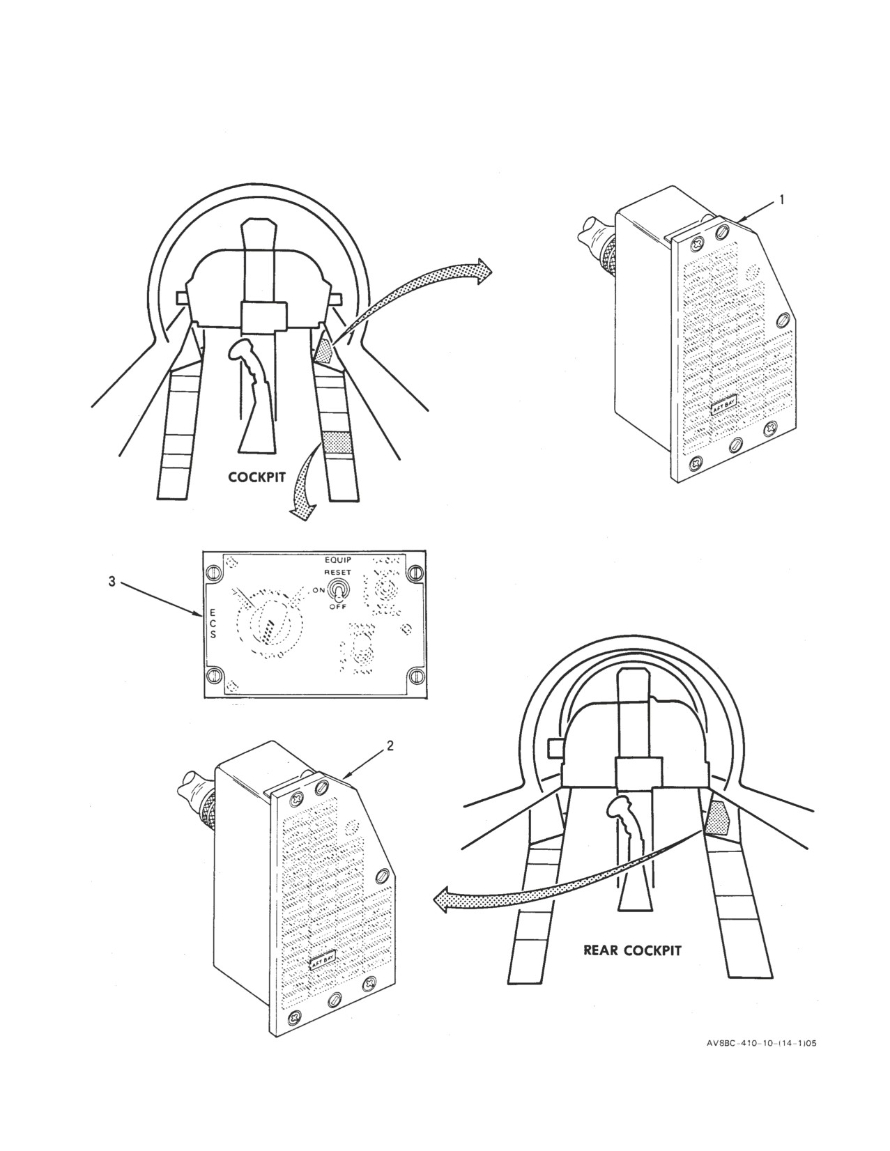
Figure 1. Rear Equipment Cooling System Component Locator (Sheet 1)
A1-AV8BC-410-100
010 00
Page 9
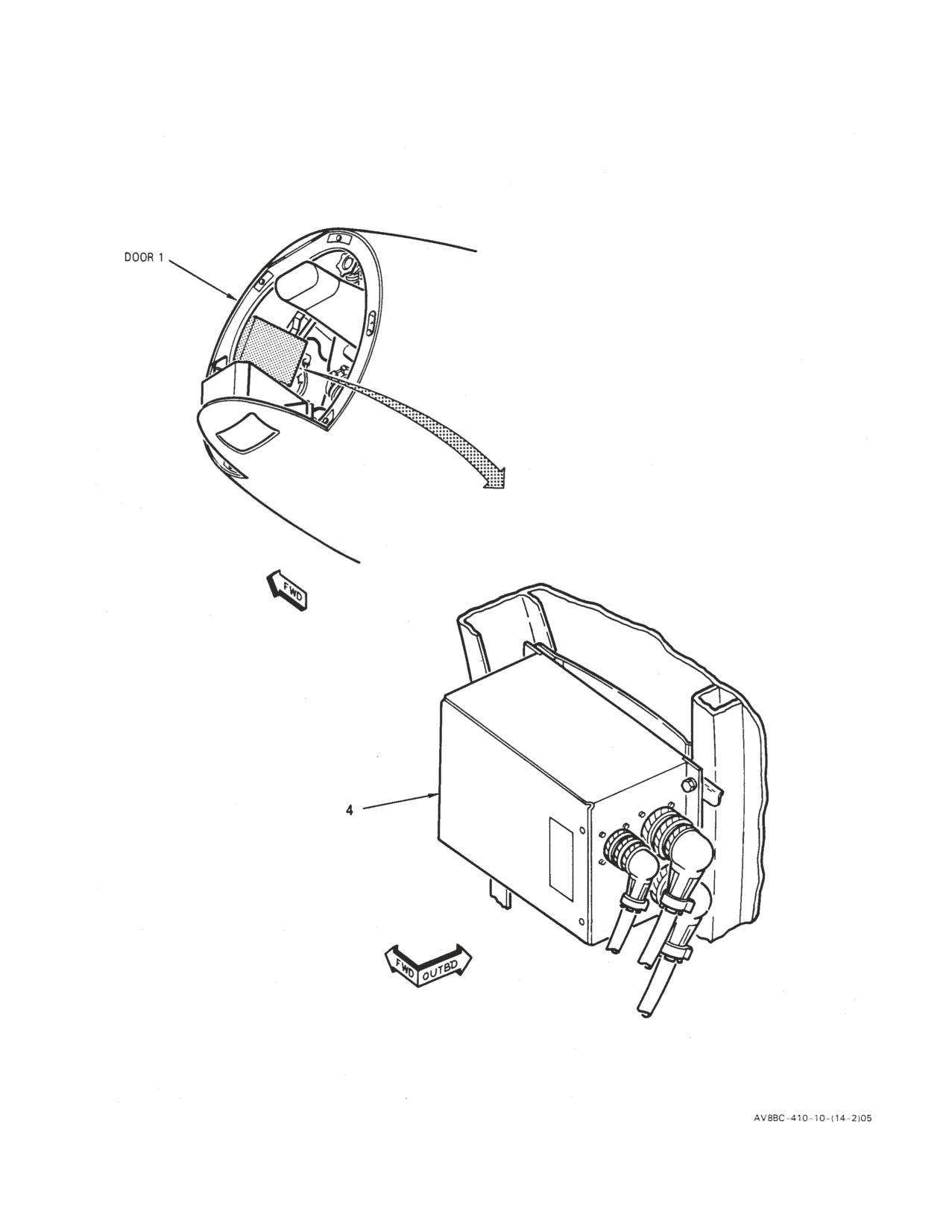
Figure 1. Rear Equipment Cooling System Component Locator (Sheet 2)
A1-AV8BC-410-100
010 00
Page 10
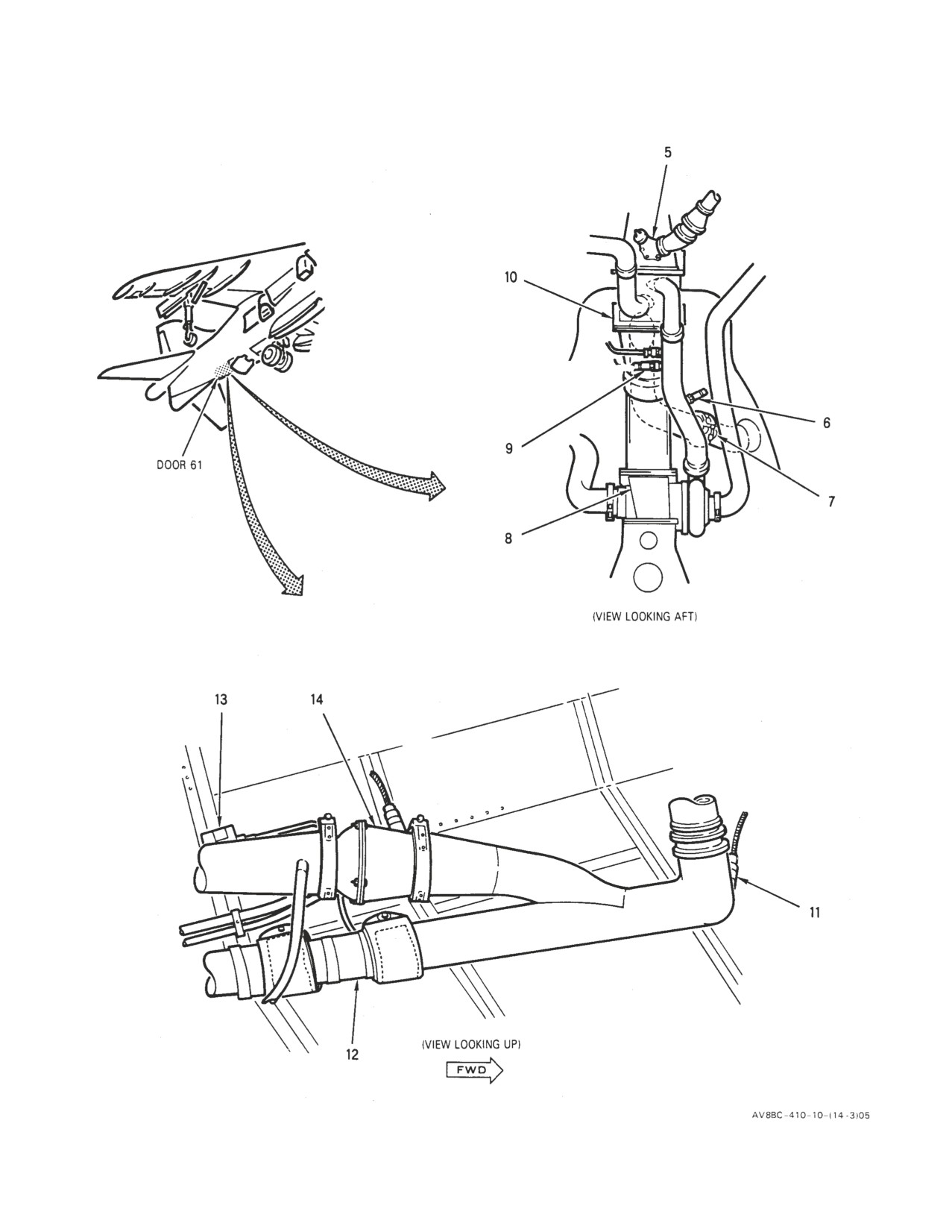
Figure 1. Rear Equipment Cooling System Component Locator (Sheet 3)
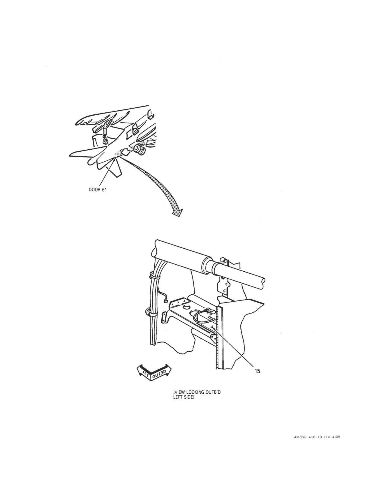
A1-AV8BC-410-100
010 00
Page 11
Figure 1. Rear Equipment Cooling System Component Locator (Sheet 4)
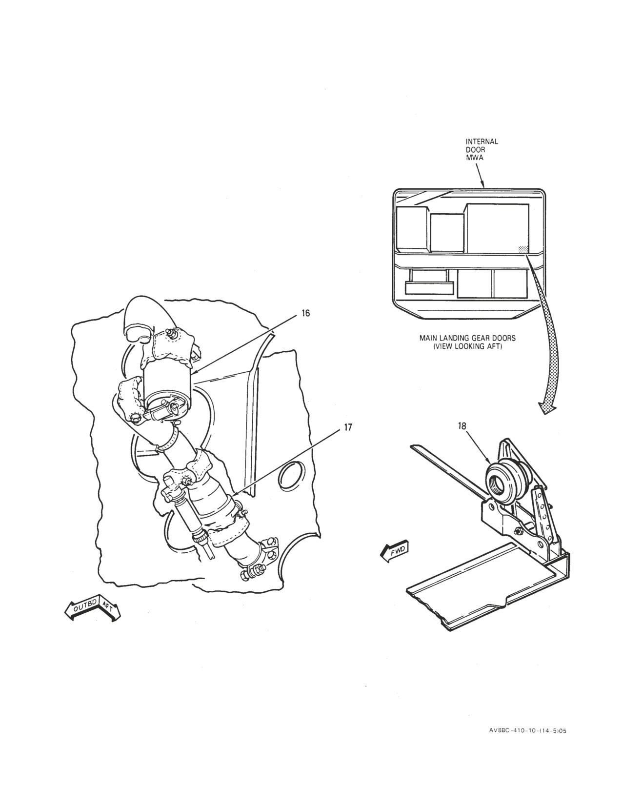
A1-AV8BC-410-100
010 00
Page 12
Figure 1. Rear Equipment Cooling System Component Locator (Sheet 5)
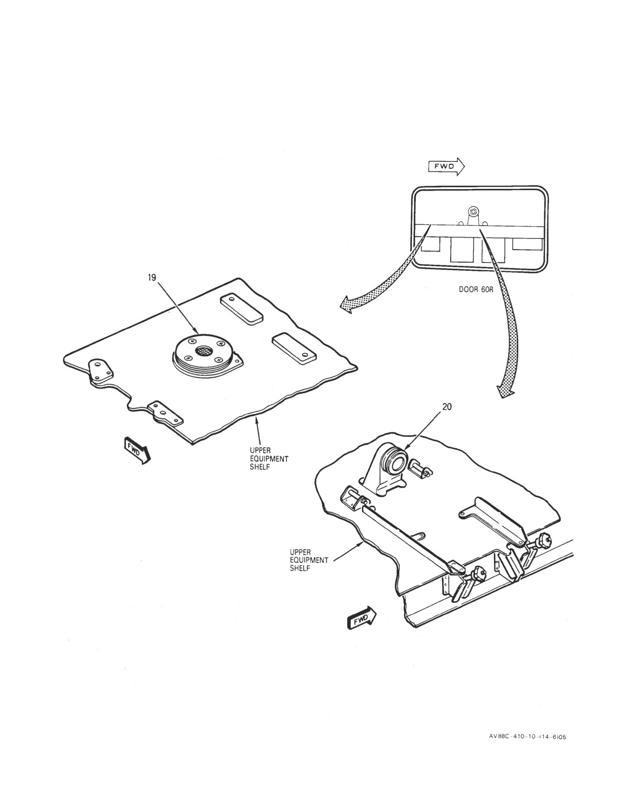
A1-AV8BC-410-100
010 00
Page 13
Figure 1. Rear Equipment Cooling System Component Locator (Sheet 6)
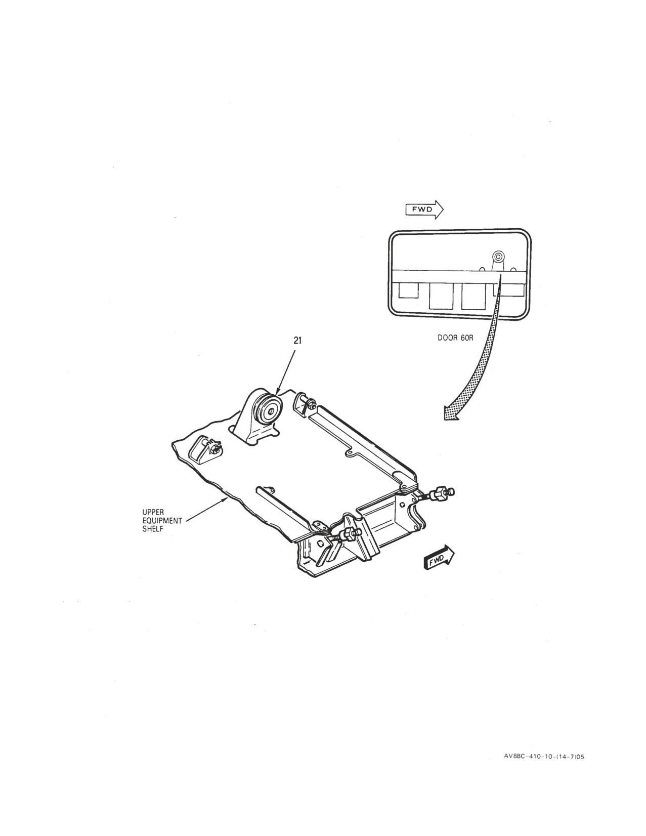
A1-AV8BC-410-100
010 00
Page 14
Figure 1. Rear Equipment Cooling System Component Locator (Sheet 7)
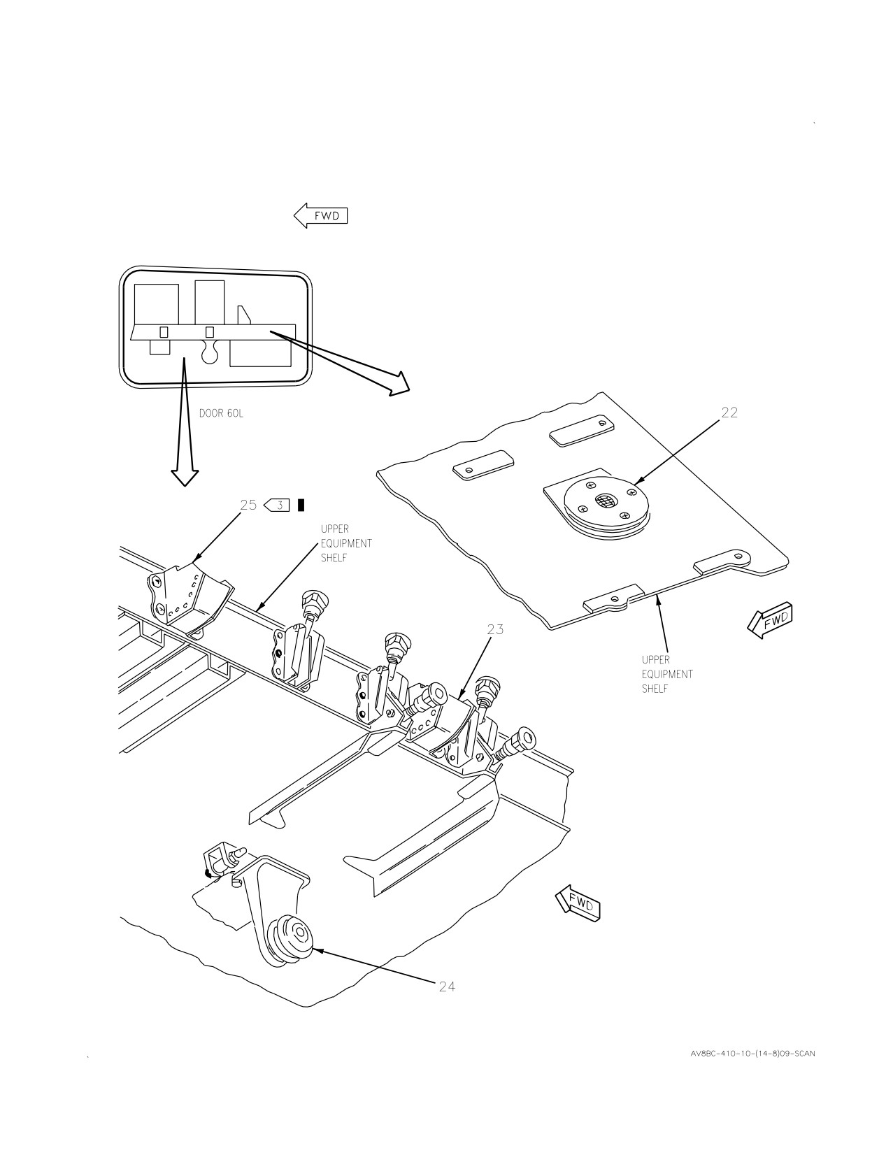
A1-AV8BC-410-100
010 00
Change 3
Page 15
Figure 1. Rear Equipment Cooling System Component Locator (Sheet 8)
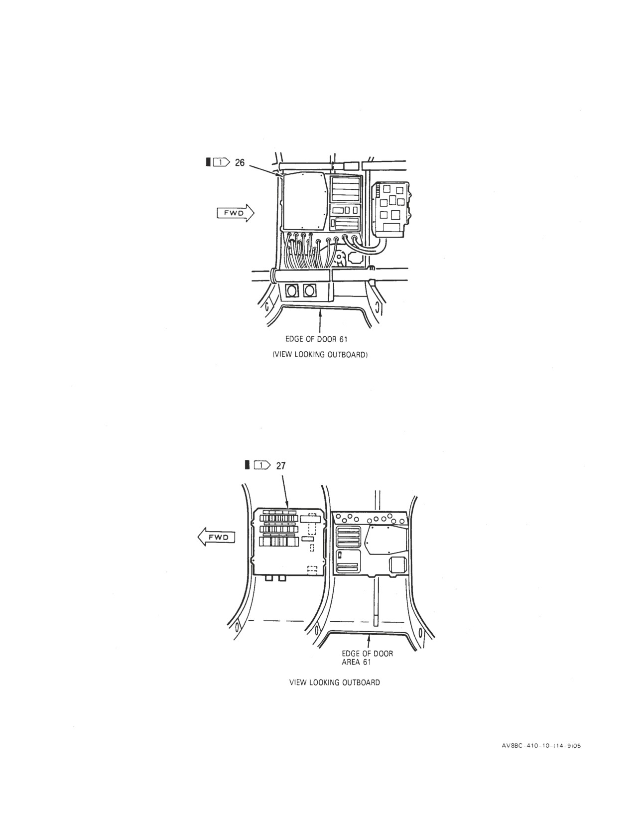
A1-AV8BC-410-100
010 00
Page 16
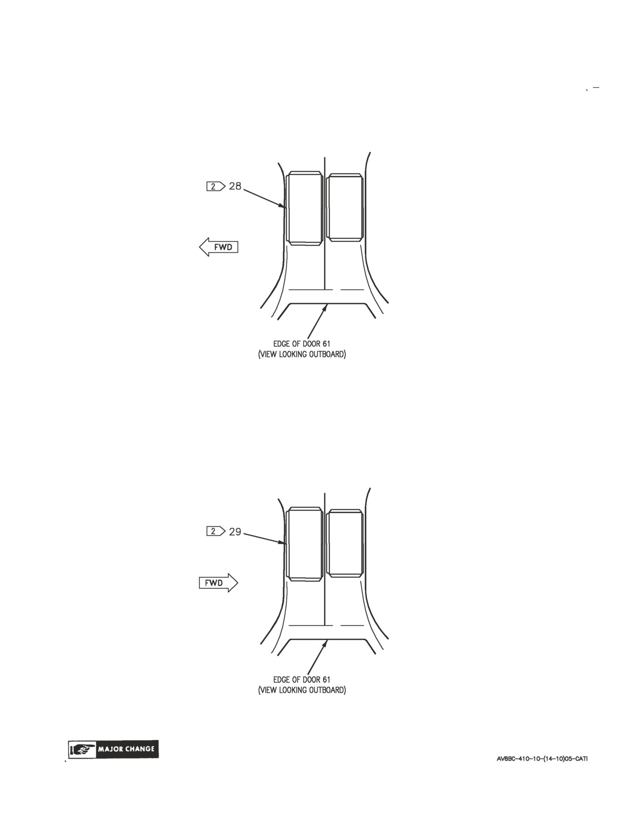
Figure 1. Rear Equipment Cooling System Component Locator (Sheet 9)
A1-AV8BC-410-100
010 00
Page 17
Figure 1. Rear Equipment Cooling System Component Locator (Sheet 10)

A1-AV8BC-410-100
010 00
Change
4
Page
18
Nomenclature
Index No.
Ref Des
2
AC ESSENTIAL PANEL ASSEMBLY
29
52A-N131
REAR COOL FAN (ZONE C5)
22CBN010
REAR COOL FAN (ZONE D5)
22CBN011
REAR COOL FAN (ZONE E5)
22CBN012
TERMINAL BOARD
52TBN139
60 SECOND DELAY ECS RELAY
22K-N056
REAR COOL FAN CONTROL RELAY
22K-N013
ANNUNCIATOR LIGHT CONTROLLER
4
27A-D007
1
AFT RELAY PANEL ASSEMBLY
27
52A-P016
60 SEC DELAY ECS RELAY
22K-P056
CAUTION/ADVISORY INDICATOR LIGHT
1
27A-F011
ASSEMBLY AFT BAY CAUTION LIGHT
COMPUTER CP-1293/ALR-67(V) COOLING AIR
23
—
OUTLET
2
DC ESSENTIAL/MAIN PANEL ASSEMBLY
28
52A-P133
ECS REAR (ZONE D4)
22CBP001
REAR EQUIPMENT COOLING CONTROL
22K-P004
RELAY
DIGITAL DATA COMPUTER COOLING AIR
21
—
FITTING
1
DISTRIBUTION PANEL ASSEMBLY
26
52A-N025
ECS REAR (ZONE B7)
22CBN001
REAR COOL FAN (ZONE C7)
22CBN010
REAR COOL FAN (ZONE D7)
22CBN011
REAR COOL FAN (ZONE E7)
22CBN012
TERMINAL BOARD
52TBN091
REAR EQP BAY COOLING CONTROL RELAY
22K-N004
REAR COOLING FAN CONTROL RELAY
22K-N013
ECS CONTROL PANEL ASSEMBLY
3
22A-F048
EQUIPMENT SWITCH
22S-F003
4
FLAP ELECTRONIC CONTROLLER COOLING AIR
20
—
FITTING
5
DIGITAL FLAP CONTROLLER COOLING AIR FIT-
20
—
TING
FLIGHT CONTROL COMPUTER CP-1743/
22
—
ASW-46(V) COOLING AIR FITTING
GENERATOR CONTROL UNIT COOLING AIR FIT-
24
—
TING
Figure 1. Rear Equipment Cooling System Component Locator (Sheet
11)

A1-AV8BC-410-100
010 00
Change
7
Page
19
Nomenclature
Index No.
Ref Des
3
RADIO-RECEIVER TRANSMITTER RT-1159/A
25
—
COOLING AIR OUTLET
REAR CAUTION/ADVISORY INDICATOR LIGHT
2
27A-H045
ASSEMBLY
AFT BAY CAUTION LIGHT
REAR ECS AIR FILTER ASSEMBLY
16
22FAT517
REAR ECS AIR INLET TEMPERATURE SWITCH
11
22S-N006
REAR ECS CHECK VALVE
7
22VAN523
REAR ECS COLD AIR UNIT
8
22MAP519
REAR ECS COLD AIR UNIT PRESSURE SWITCH
6
22S-N008
REAR ECS GROUND COOLING FAN
14
22B-N014
REAR ECS GROUND COOLING FAN PRESSURE
9
22S-P009
SWITCH
REAR ECS GROUND COOLING FAN SPEED
15
22A-N049
SENSOR
REAR ECS GROUND COOLING VALVE
5
22MAP522
REAR ECS HEAT EXCHANGER
10
22MAP518
REAR ECS PRESSURE REDUCING AND SHUTOFF
17
22L-T005
VALVE
REAR ECS TEMPERATURE CONTROL VALVE
13
22MAN520
REAR ECS TEMPERATURE SENSOR
12
22MAN521
SIGNAL DATA CONVERTER CV-3736/A COOLING
19
—
AIR FITTING
STORES MANAGEMENT COMPUTER CP-1451/
18
—
AYQ-13 COOLING AIR FITTING
LEGEND
1
162747; ALSO 162963 THRU 163861 BEFORE AV8AFC-416.
2
164113 AND UP; ALSO 162963 THRU 163861 AFTER AV8AFC-416.
3
BEFORE AV8AFC-354.
4
BEFORE AV8AFC-393.
5
AFTER AV8AFC-393.
Figure 1. Rear Equipment Cooling System Component Locator (Sheet 12)
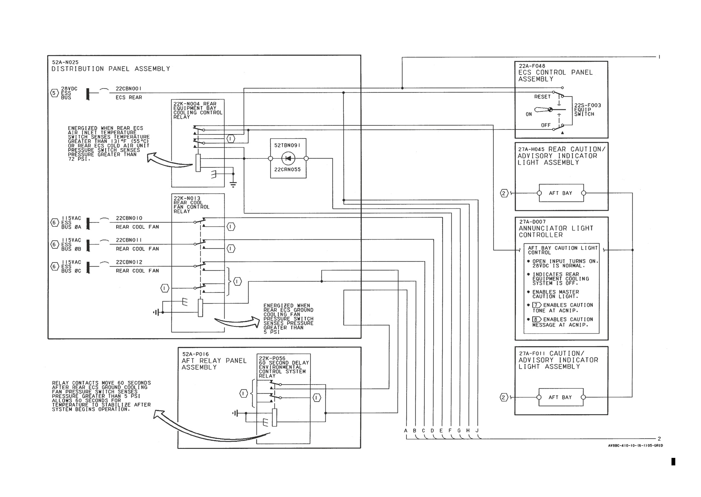
A1-AV8BC-410-100
010 00
Change 7
Page 20
Figure 2. Rear Equipment Cooling System Simplified Schematic-162747; ALSO 162963 THRU 163861 BEFORE AV8AFC-416 (Sheet 1)
Figure 2.
Figure 2.
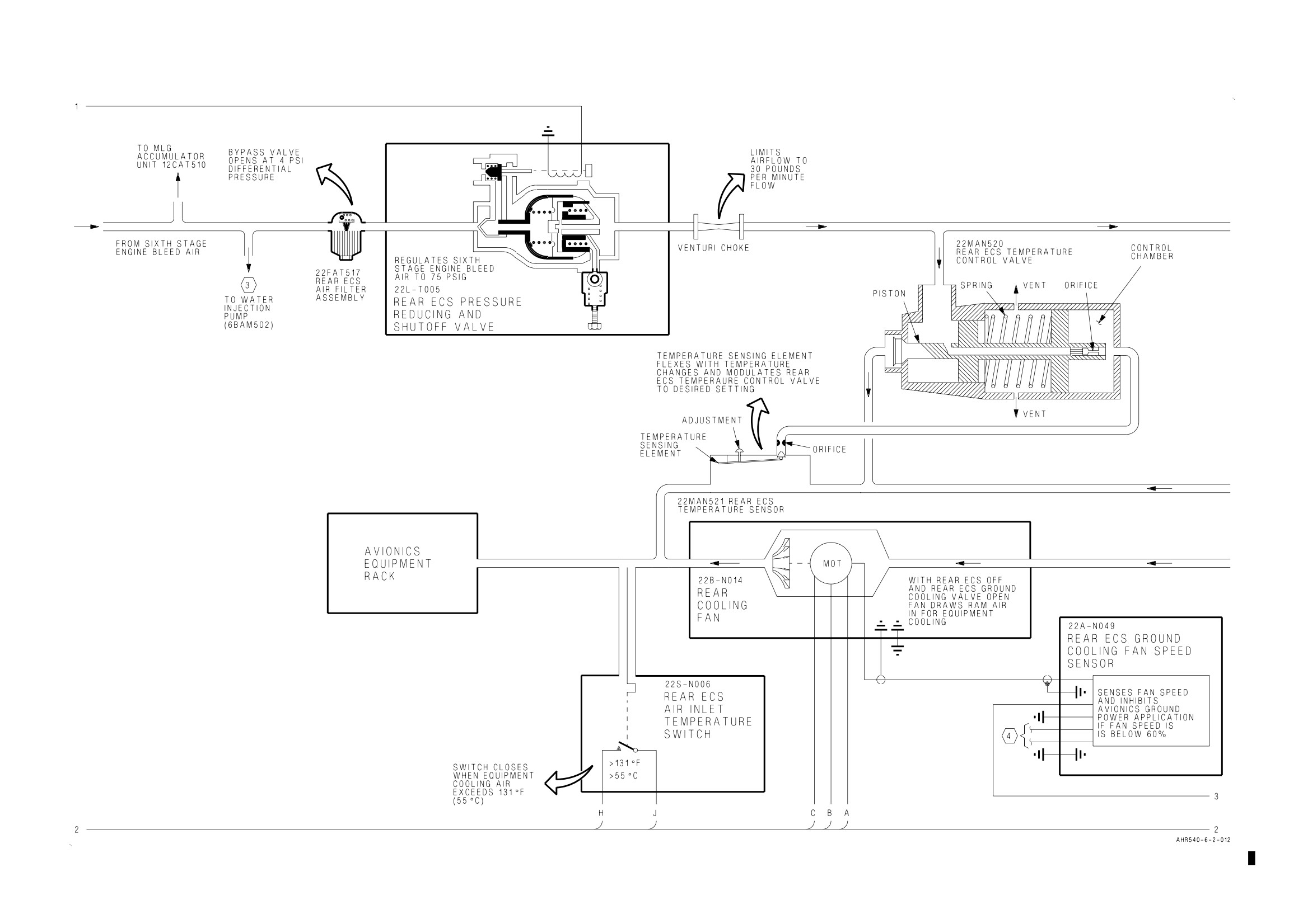
A1-AV8BC-410-100
010 00
Change 7
Page 21
Figure 2. Rear Equipment Cooling System Simplified Schematic-162747; ALSO 162963 THRU 163861 BEFORE AV8AFC-416 (Sheet 2)
Figure 2.
Figure 2.
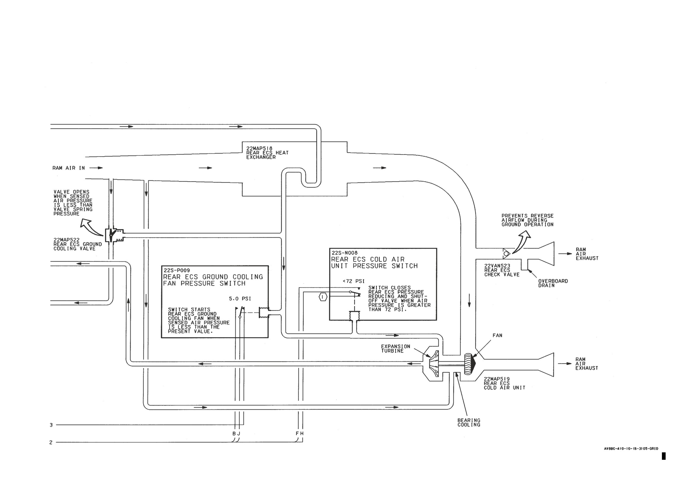
A1-AV8BC-410-100
010 00
Change 7
Page 22
Figure 2. Rear Equipment Cooling System Simplified Schematic-162747; ALSO 162963 THRU 163861 BEFORE AV8AFC-416 (Sheet 3)
Figure 2.
Figure 2.
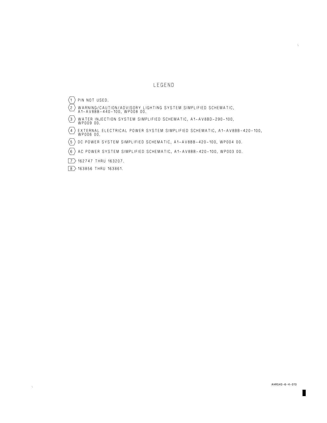
A1-AV8BC-410-100
010 00
Change 7
Page 23
Figure 2. Rear Equipment Cooling System Simplified Schematic-162747; ALSO 162963
THRU 163861 BEFORE AV8AFC-416 (Sheet 4)
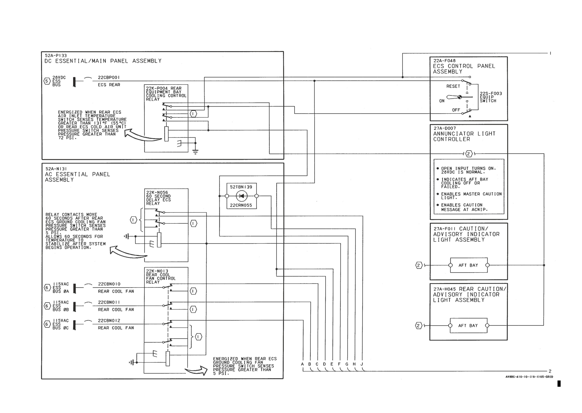
A1-AV8BC-410-100
010 00
Change 7
Page 24
Figure 3. Rear Equipment Cooling System Simplified Schematic-164113 AND UP; ALSO 162963 THRU 163861 AFTER AV8AFC-416 (Sheet 1)
Figure 3.
Figure 3.
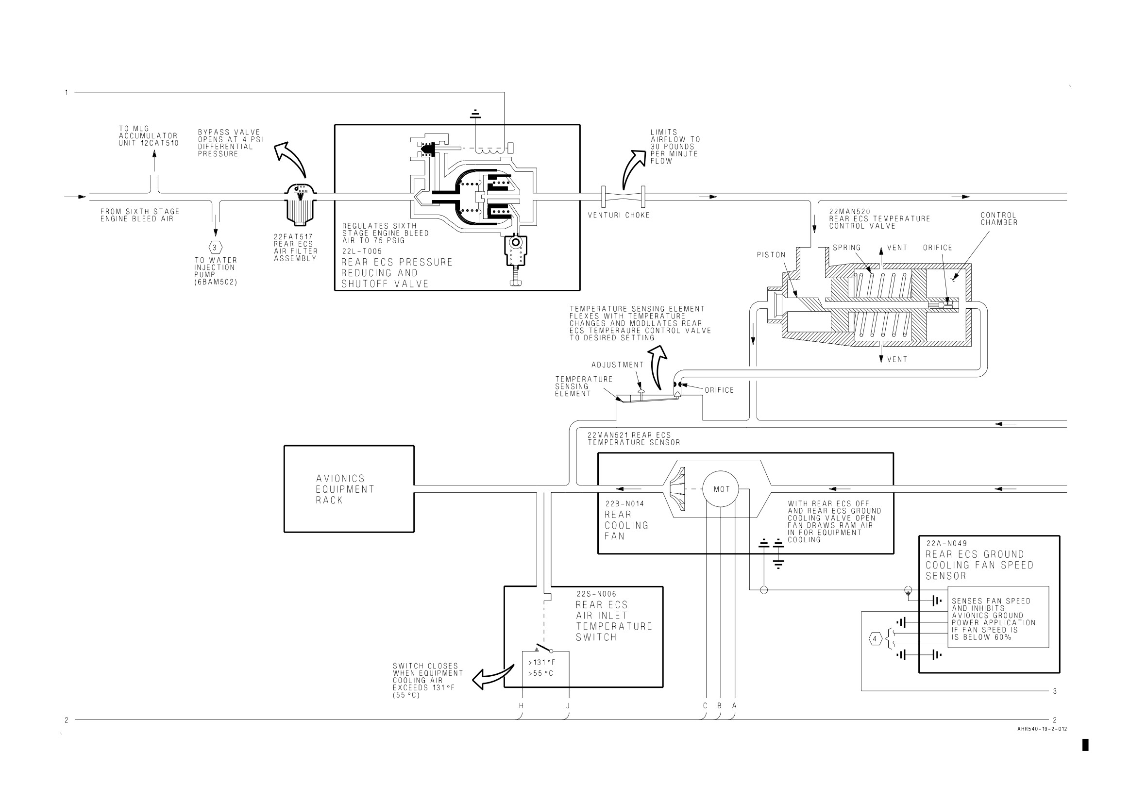
A1-AV8BC-410-100
010 00
Change 7
Page 25
Figure 3. Rear Equipment Cooling System Simplified Schematic-164113 AND UP; ALSO 162963 THRU 163861 AFTER AV8AFC-416 (Sheet 2)
Figure 3.
Figure 3.
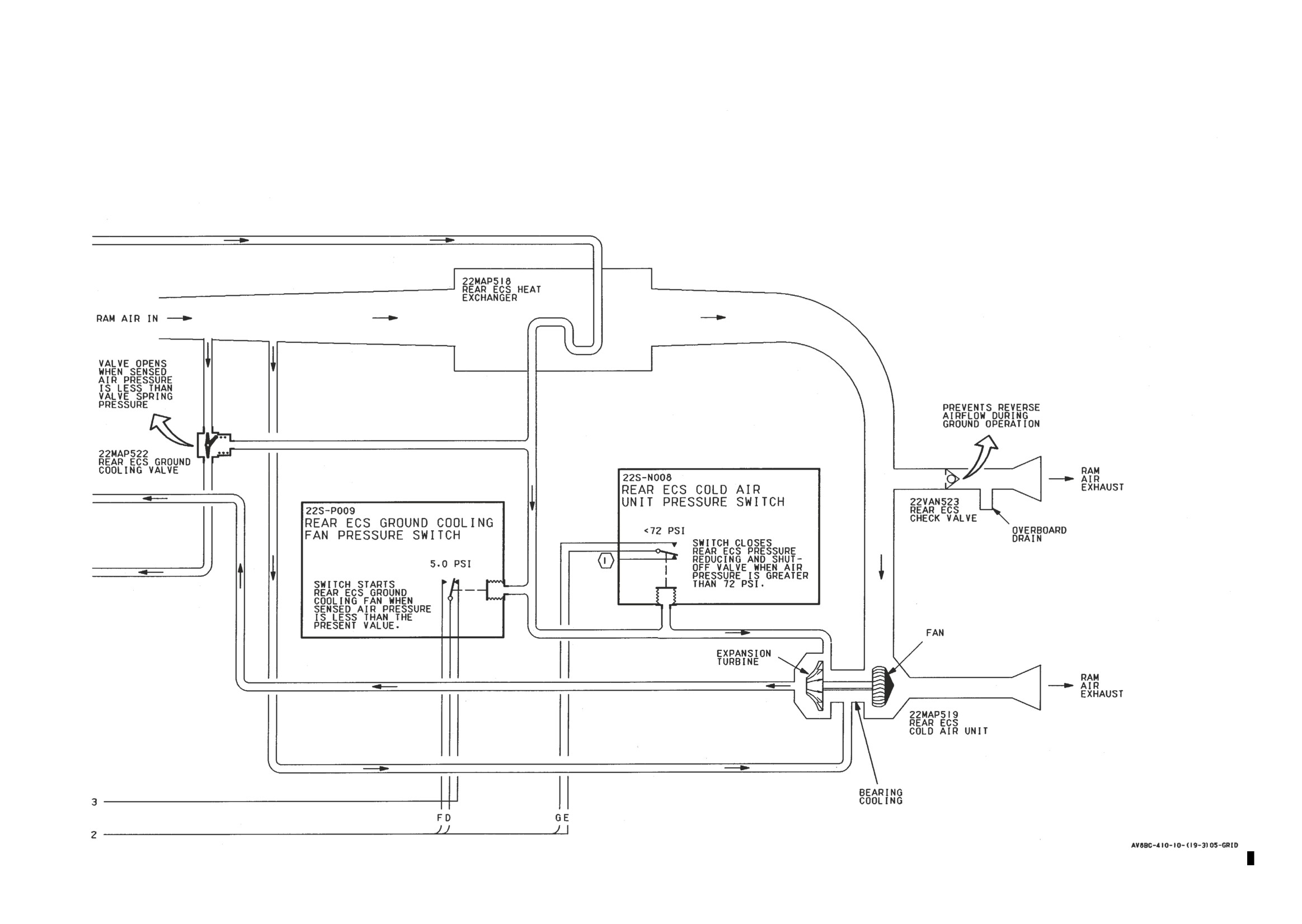
A1-AV8BC-410-100
010 00
Change 7
Page 26
Figure 3. Rear Equipment Cooling System Simplified Schematic-164113 AND UP; ALSO 162963 THRU 163861 AFTER AV8AFC-416 (Sheet 3)
Figure 3.
Figure 3.
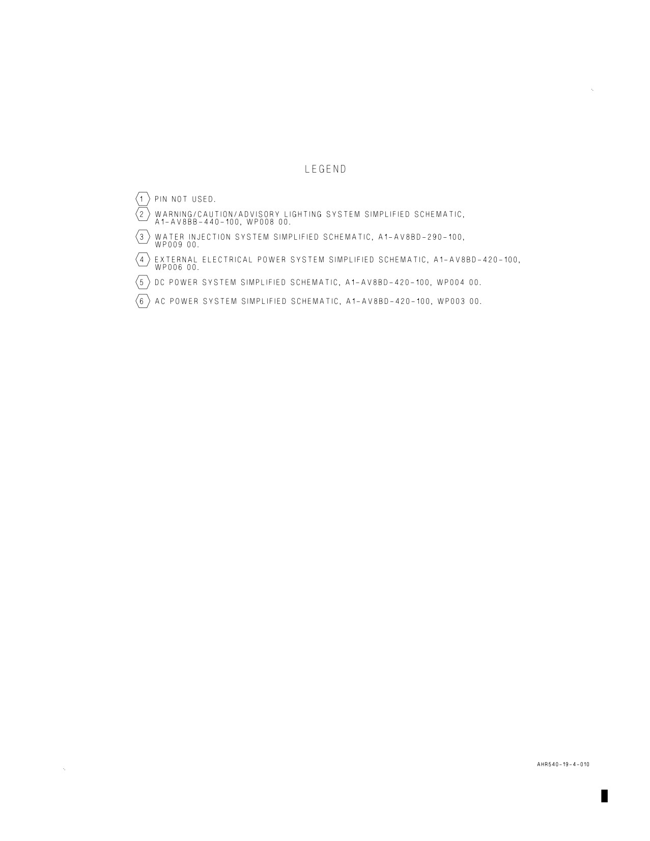
A1-AV8BC-410-100
010 00
Change 7
Page 27/(28 blank)
Figure 3. Rear Equipment Cooling System Simplified Schematic-164113 AND UP; ALSO
162963 THRU 163861 AFTER AV8AFC-416 (Sheet 4)
A1-AV8BC-410-100
011 00
Change 7 - 15 May 2004
Page 1
ORGANIZATIONAL MAINTENANCE
PRINCIPLES OF OPERATION
DESCRIPTION AND OPERATION
ON-BOARD OXYGEN GENERATING SYSTEM
Reference Material
Ejection Seat and Canopy System
A1-AV8BB-120-100
Description - Ejection Seat System
WP003 00
Environmental Control System
A1-AV8BC-410-100
Component Locator - On-Board Oxygen Generating System
WP012 00
Power Plant and Related Systems
A1-AV8BD-290-100
Basic Engine
WP003 00
Electrical Systems
A1-AV8BB-420-100
DC Power System
WP004 00
Electrical Systems
A1-AV8BD-420-100
DC Power System
WP004 00
Lighting Systems
A1-AV8BB-440-100
Warning/Caution/Advisory Lighting System
WP007 00
Alphabetical Index
Subject
Page No.
Description
2
Component Description
3
Mixer/Diffuser Duct
3
OBOGS Bleed Air Shutoff Valve
3
OBOGS Heat Exchanger
3
OBOGS Heat Exchanger Ejector Filter
3
OBOGS Overtemperature Switch
3
OBOGS Pressure Relief Valve
3
OBOGS Test Port
3
Oxygen Concentrator GGU-7/A
3
Oxygen Disconnect
3
Oxygen Monitor Assembly CRU-91/A
3
Oxygen Monitor Assembly CRU-99/A
3
Oxygen Plenum
3
Rear Oxygen Disconnect
3
Rear Oxygen Plenum
3
Related Systems
3
Basic Engine
3
A1-AV8BC-410-100
011 00
Change 7
Page 2
Alphabetical Index (Continued)
Subject
Page No.
DC Power System
3
Ejection Seat System
3
Warning/Caution/Advisory Lighting System
3
System Controls and Indicators
4
OBOGS O Temp Indicator
4
OEAS Htr Cont Rly
4
OXY Caution Lights
4
OXY Shutoff Valve
4
OXY Switch
4
System Description
2
On-Board Oxygen Generating System Simplified Schematic-TAV-8B 162747; ALSO 162963
THRU 163861 BEFORE AV8AFC-416, Figure 1
8
On-Board Oxygen Generating System Simplified Schematic-TAV-8B 164113 AND UP; ALSO
162963 THRU 163861 AFTER AV8AFC-416, Figure 2
12
Operation
4
Component Operation
4
Mixer/Diffuser Duct
5
OBOGS Bleed Air Shutoff Valve
4
OBOGS Heat Exchanger
5
OBOGS Heat Exchanger Ejector Filter
5
OBOGS Overtemperature Switch
5
OBOGS Pressure Relief Valve
5
OBOGS Test Port
6
Oxygen Concentrator GGU-7/A
5
Oxygen Disconnect
6
Oxygen Monitor Assembly CRU-91/A or CRU-99/A
6
Oxygen Plenum
5
Rear Oxygen Disconnect
6
Rear Oxygen Plenum
6
System Operation
6
Emergency Operation
7
Normal Operation
6
Record of Applicable Technical Directives
Type/
Date
Date
Title and ECP or RAMEC No.
Remarks
Number
Incorp.
AV8AFC-416
— TAV-8B Polyimide Wire Replacement/
15 May 04
—
Power Wire Separation (ECP MDA-AV8B-
0277)
1. DESCRIPTION.
remaining gas is an oxygen rich breathing mixture
for crewmembers.
2. SYSTEM DESCRIPTION. The on-board oxygen
generating system (OBOGS) removes nitrogen and
other contaminants from engine bleed air. The
A1-AV8BC-410-100
011 00
Change 7
Page 3
3. COMPONENT DESCRIPTION. System
sensor, processing electronics, built-in test (BIT), a
components are described and listed in paragraphs
circuit heater and a pressure controlled sensing
below. For component locator, refer to WP012 00.
chamber.
4. OBOGS Bleed Air Shutoff Valve. The OBOGS
14. Oxygen Monitor Assembly CRU-99/A. The
bleed air shutoff valve is a motor driven, butterfly
oxygen monitor assembly CRU-99/A is a solid state
type shutoff valve. The valve is made up of an
electronic processor. The monitor is made up of
actuator, electric drive motor, limit switches, a
processing electronics, two built-in test (BIT)
housing, and an external position indicator.
buttons, a circuit heater and a pressure controlled
sensing chamber.
5. OBOGS Heat Exchanger. The OBOGS heat
exchanger is a cross-flow air to air heat exchanger.
15. Oxygen Disconnect. The oxygen disconnect is
The heat exchanger is made up of a tubular core,
a console mounted, quick release disconnect.
ejector, and ejector filter enclosed in a stainless
steel case. The heat exchanger case is wrapped with
16. Rear Oxygen Disconnect. The rear oxygen
insulation.
disconnect is a console mounted, quick release
disconnect.
6. OBOGS Heat Exchanger Ejector Filter. The
OBOGS heat exchanger ejector filter is an in-line
17. OBOGS Test Port. The OBOGS test port is an
wire mesh filter. The filter element is brazed to a
in-line, capped, tee fitting.
threaded cap. The filter can be cleaned and
replaced independent of the OBOGS heat
18. RELATED SYSTEMS. Related systems are
exchanger.
described in paragraphs below.
7. Mixer/Diffuser Duct. The mixer/diffuser duct is
19. Ejection Seat System. The ejection seats
a stainless steel machined duct.
(A1-AV8BB-120-100, WP003 00) have an
emergency oxygen cylinder stored in each survival
8. OBOGS Pressure Relief Valve. The OBOGS
kit. The emergency oxygen supply can be manually
pressure relief valve is an in-line, mechanical,
actuated if OBOGS is off or fails, or automatically
pressure relief valve.
actuated during emergency egress.
9. OBOGS Overtemperature Switch. The OBOGS
20. Basic Engine. The engine (A1-AV8BD-290-100,
overtemperature switch is a sealed, bi-metallic
WP003 00) provides hot, eighth stage compressor
electrical switch designed into a threaded plug for
bleed air to the on-board oxygen generating system.
in-line mounting.
21. DC Power System. The DC power system on
10. Oxygen Concentrator GGU-7/A. The oxygen
162747; ALSO 162963 THRU 163861 BEFORE
concentrator GGU-7/A is an electrical/mechanical
AV8AFC-416 (A1-AV8BB-420-100, WP004 00) or
device. The concentrator is made up of a rotary
164113 AND UP; ALSO 162963 THRU 163861
valve, two molecular sieve beds, drive/servo motor,
AFTER AV8AFC-416 (A1-AV8BD-420-100, WP004
temperature control circuit, plenum assembly, air
00) provides emergency and main 28vdc power to
heater, inlet filter, pressure reducer, and an
the on-board oxygen generating system.
insulating shroud.
22. Warning/Caution/Advisory Lighting System.
11. Oxygen Plenum. The oxygen plenum is an
The warning/caution/advisory lighting system
in-line, 100 cubic inch, aluminum storage cylinder.
(A1-AV8BB-440-100, WP007 00) provides visual
indication of normal aircraft functions and system
12. Rear Oxygen Plenum. The rear oxygen plenum
malfunctions affecting safety of flight operations.
is an in-line, 100 cubic inch, aluminum storage
The warning/caution/advisory lighting system
cylinder.
includes the annunciator light controller and the
caution/advisory indicator light assembly. The
13. Oxygen Monitor Assembly CRU-91/A. The
annunciator light controller receives data from
oxygen monitor assembly CRU-91/A is an electronic
various aircraft systems and provides logic to turn
processor. The monitor is made up of an oxygen
on and off warning/caution/advisory lights.