NATOPS FLIGHT MANUAL NAVY MODEL AV--8B/TAV--8B 161573 AND UP AIRCRAFT (2008) - page 11
A1-AV8BB-NFM-000
Page
Page
No.
No.
TRUE heading pushbutton (TAV--8B with
Gross weight and air temperature
2--85
OMNI 7.1 and day attack aircraft)
23--42
Lateral asymmetries
2--85
Turbulent air and thunderstorm operation
20--3
VREST computer
2--77
Angle--of--attack system failure
20--3
VREST displays
2--77
Approaching the storm
20--3
Bingo display
2--79
In the storm
20--3
Cruise display
2--78
Penetration
20--3
Engine data entry
2--79
Penetration airspeeds
20--3
Short takeoff display
2--77
Vertical takeoff and landing display
2--77
VSTOL master mode
23--72
U
Angle of attack analog scale
23--76
Uncommanded flap motion
15--47
Auxiliary heading
23--72
Uncommanded nose down pitch
Depressed attitude symbol
23--76
movement
15--47
F (flap)
23--72
Unqualified
25--1
FPM
23--72
Unusual attitude recovery
20--4
J (jet pipe temperature)
23--76
Up arrow pushbutton
23--41
N (nozzle)
23--72
UPDT/PVU Pushbutton
23--42
Nosewheel steering mode
Updating the EPC
19--1
(aircraft after AFC--391)
23--75
Upfront control
2--67, 2--68
Nozzle rotation airspeed cue
23--76
Altitude function selector
Pitch carets cue
23--76
pushbutton
2--67
Power margin display and W
23--75
EMCON pushbutton
2--67
On/off selector pushbutton
2--67
R (rpm)
23--76
Scratchpad and keyboard
2--67
S (ground speed)
23--76
UTM data entry (OMNI 7.1 and C1+)
23--58
Sideslip indicator
23--72
UTM error vs range
Vertical flight path symbol
23--72
(OMNI 7.1 and C1+)
23--62
Vertical speed analog scale
23--72
UTM data entry (with H4.0)
23--62
UTM error vs range (OMNI 7.1 and C1+)
23--62
W
V
Waiving of minimum ground training
requirements
5--2
Velocity vector
23--71
Velocity reasonableness test
23--16
Wake turbulence
11--1
Vertical flight path symbol
23--72
Control authority
11--4
Vertical landing
7--52, 11--29
Control power
11--4
Decelerating transition to a rolling
Critical mach
11--2
vertical landing
7--54
Dynamic pressure
11--3
Fixed nozzle slow landing
7--55
Force divergence mach number/drag rise . . . 11--3
Option display unit
2--67
Kinematic coupling
11--4
Slow landing
7--55
Maneuvering mcrit
11--3
Vertical speed analog scale
23--72
Shock--induced flow separation
11--2
Visual communications
22--9
Deck/ground handling signals
22--9
Supercritical airfoil (wing)
11--4
VREST calculation considerations
2--85
Transonic wing drop
11--3
ORIGINAL
Index-20
A1-AV8BB-NFM-000
Page
Page
No.
No.
Warning/caution/advisories lights
12--2
Entering waypoint or markpoint, or
GPWS warning cues
2--115
targetpoint data
23--50
Flight position transfer page
23--58
Ground proximity warning system(trainer
Magnetic variation
23--52
(with H4.0), night attack
Manual data entry
23--50
and radar aircraft)
2--113
Offset elevation
23--52
Recovery cue
2--115
Range
23--57
Voice warnings
2--113
Targetpoint data programming
Warning/caution/advisory lights and tones
(with H4.0)
23--51
(AV--8B radar and night attack aircraft)
2--110
Transfer data page (with H4.0)
23--57
Master warning and master caution light
2--113
Transfer--from point
23--57
Warning/caution/advisory lights and tones
Transfer--to point
23--58
(TAV--8B and AV--8B day attack aircraft) . . .
2--109
Waypoint data display
23--50
Water injection system
2--13
XFER
23--58
H2O light
2--14
Waypoint, markpoint or targetpoint
H2O SEL caution light
2--14
location symbol
23--32
Water dump switch
2--14
Waypoint/markpoint or targetpoint
Water flow light
2--14
number
23--71
Water injection switch (AFT cockpit)
2--14
Waypoint, markpoint or targetpoint steering
pushbutton
23--41
Water injection system--conditioned air
2--14
Waypoint, markpoint, targetpoint, or waypoint/
Water switch
2--13
markpoint offset steering
23--65
Water tank
2--14
Waypoint or mark offset location symbol
23--43
Waveoff from vertical/slow landing
7--60
Weight limitations
4--14
Waypoint data display
23--50
Wingman
24--3
Waypoint, markpoint, targetpoint,
and offset data entry
23--50
Z
Bearing
23--52
Datum
23--52
ZOOM pushbutton (TAV--8B with H4.0 and
Elevation
23--51
radar and night attack aircraft)
23--46
ORIGINAL
Index-21/(-22 blank)
A1-AV8BB-NFM-000
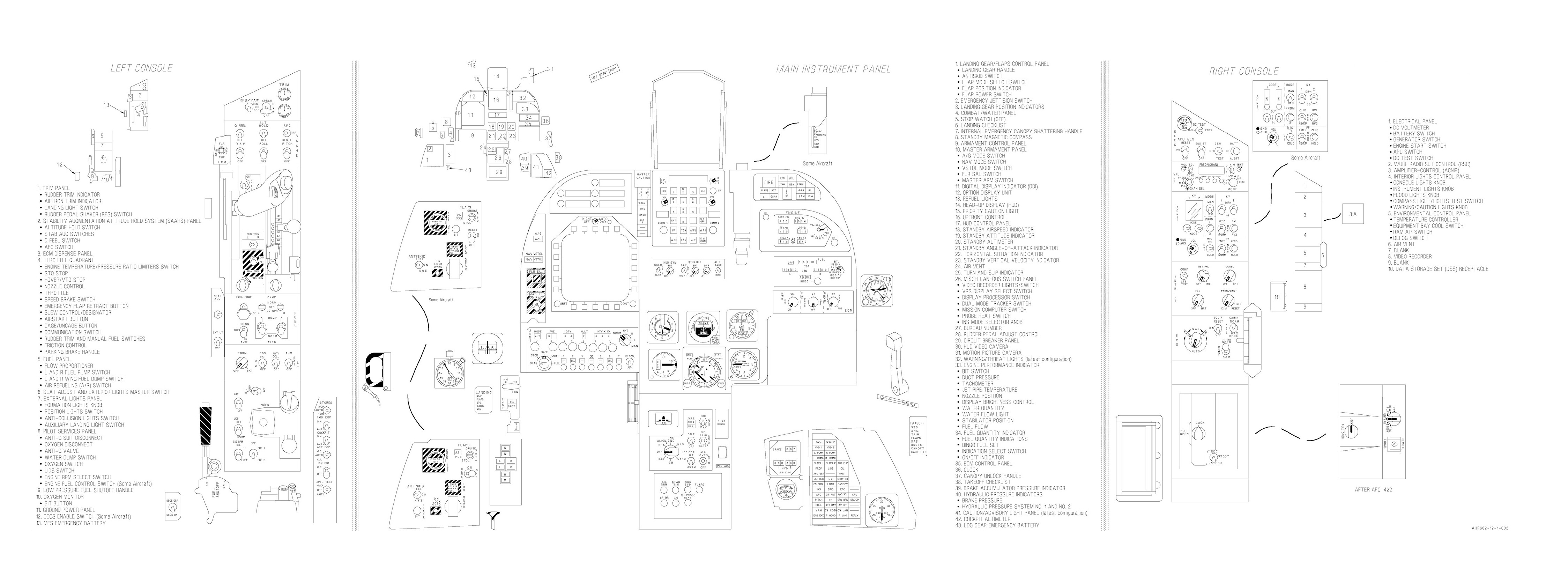
Cockpit, AV-8B 161573 Thru 163852
FO-1 (Reverse Blank)
ORIGINAL
A1-AV8BB-NFM-000
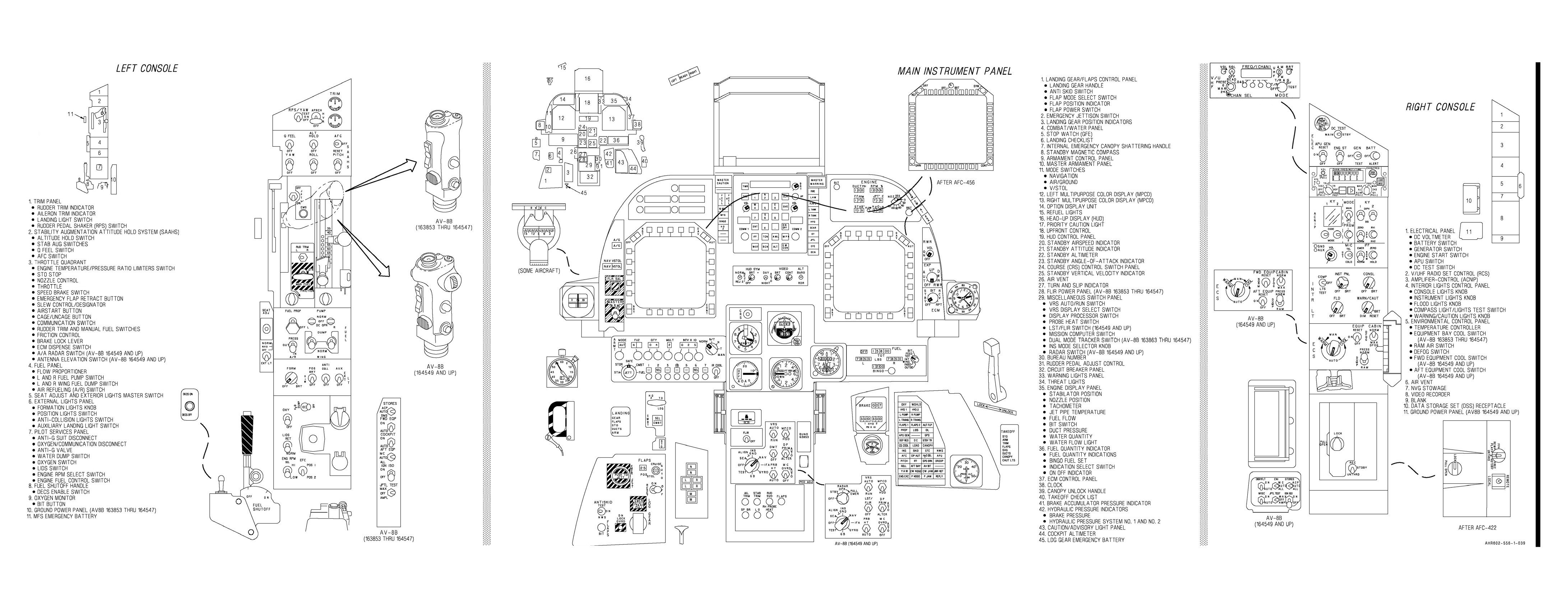
BEFORE AFC-409
Cockpit, AV-8B 163853 And Up
FO-2 (Reverse Blank)
ORIGINAL
A1-AV8BB-NFM-000
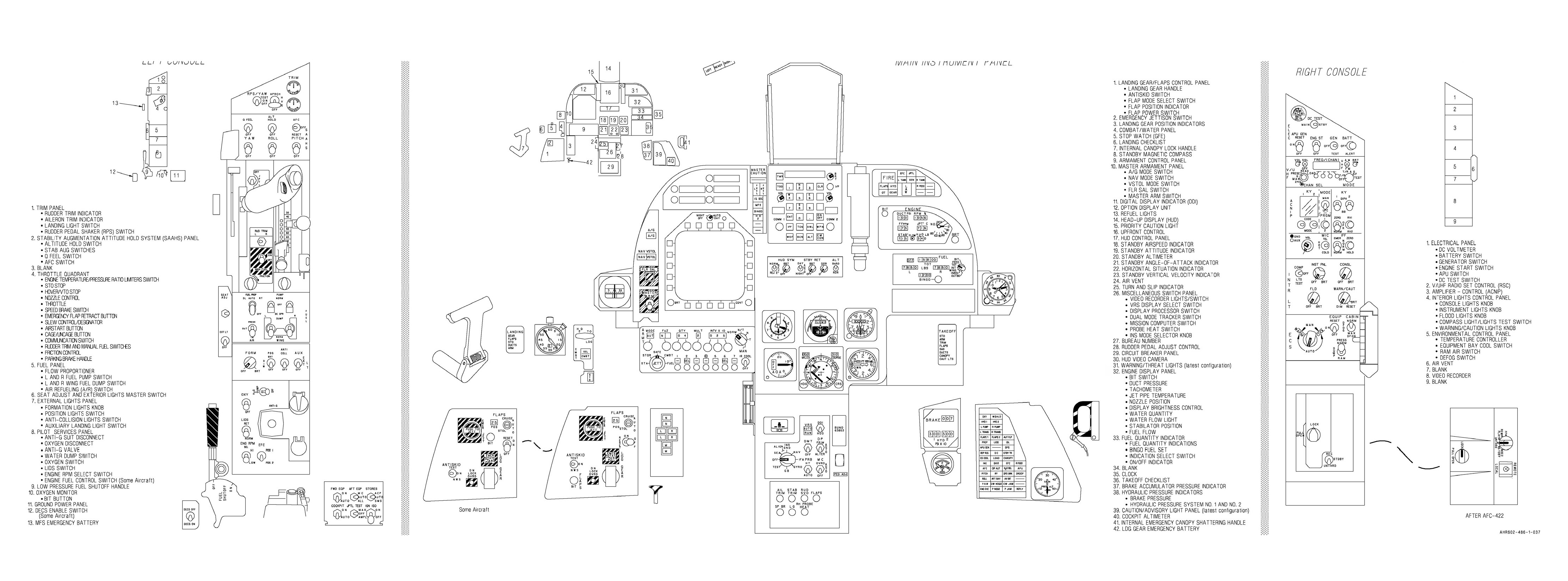
Cockpit, TAV-8B
ORIGINAL
FO-3 (Reverse Blank)
A1-AV8BB-NFM-000
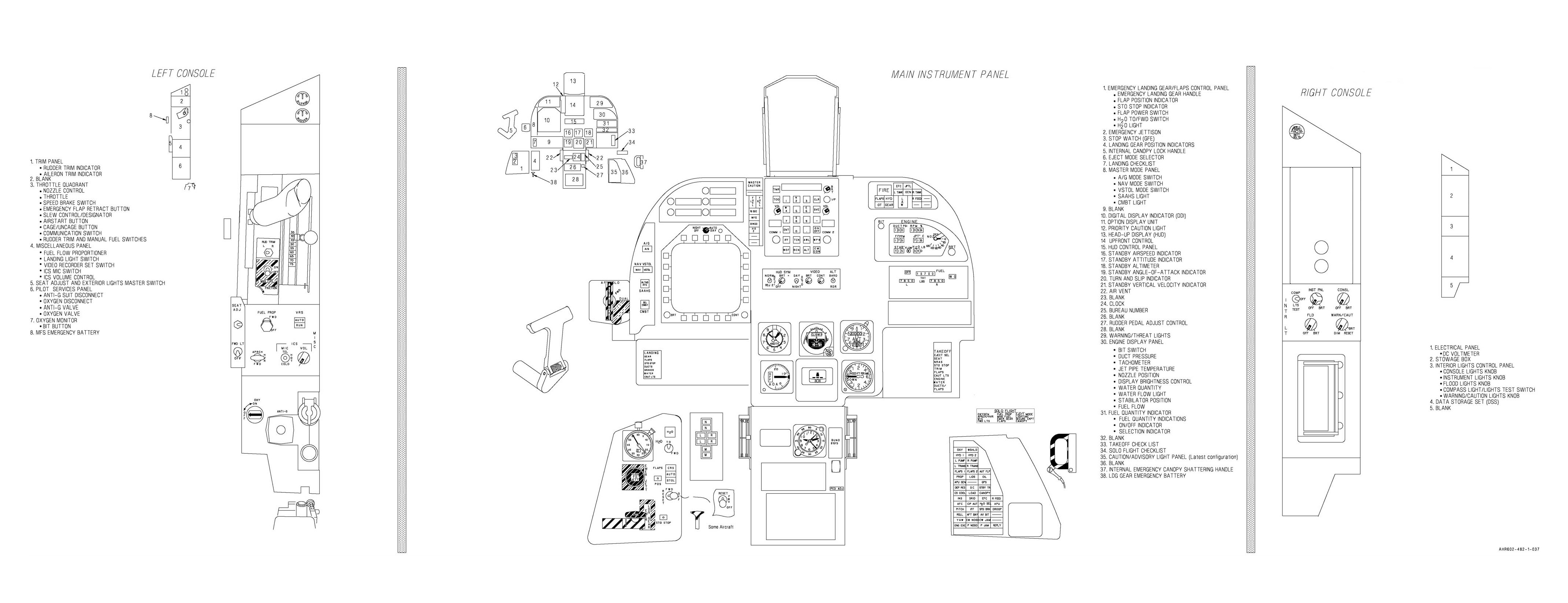
Rear Cockpit, TAV-8B
ORIGINAL
FO-4 (Reverse Blank)
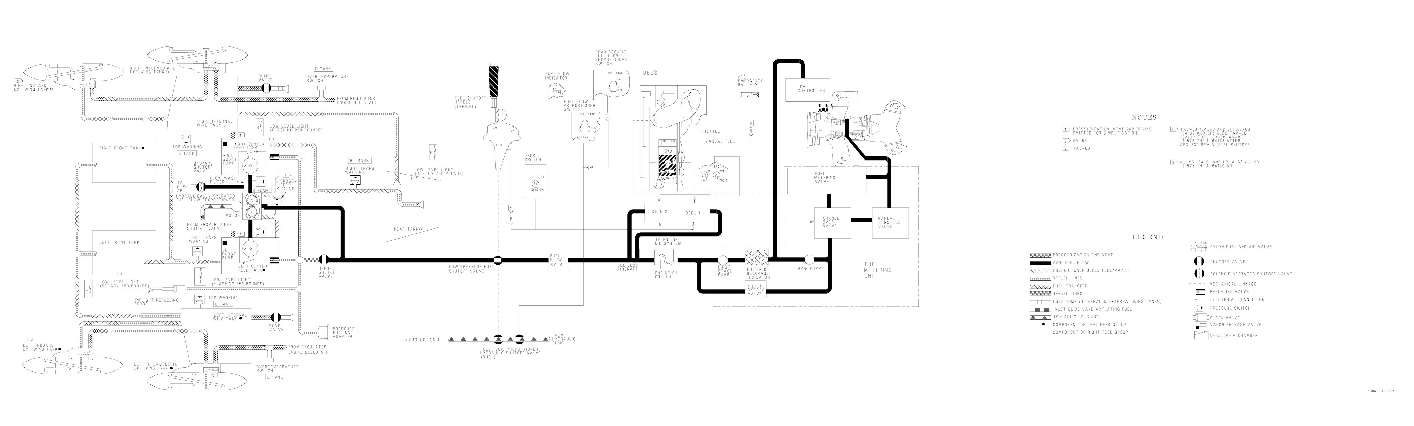
A1-AV8BB-NFM-000
Aircraft and Engine Fuel System
ORIGINAL
FO-5 (Reverse Blank)
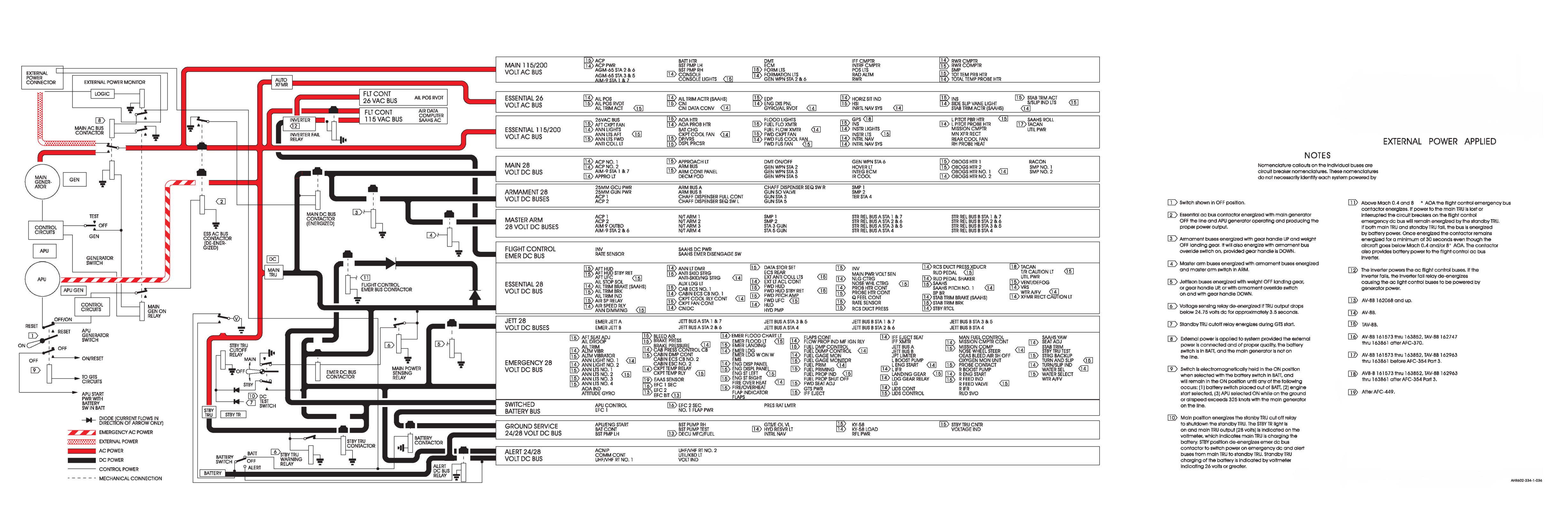
A1-AV8BB-NFM-000
Electrical System, AV-8B 161573 Thru 163852, TAV-8B 162747 Thru 163861
ORIGINAL
FO-6 (Reverse Blank)
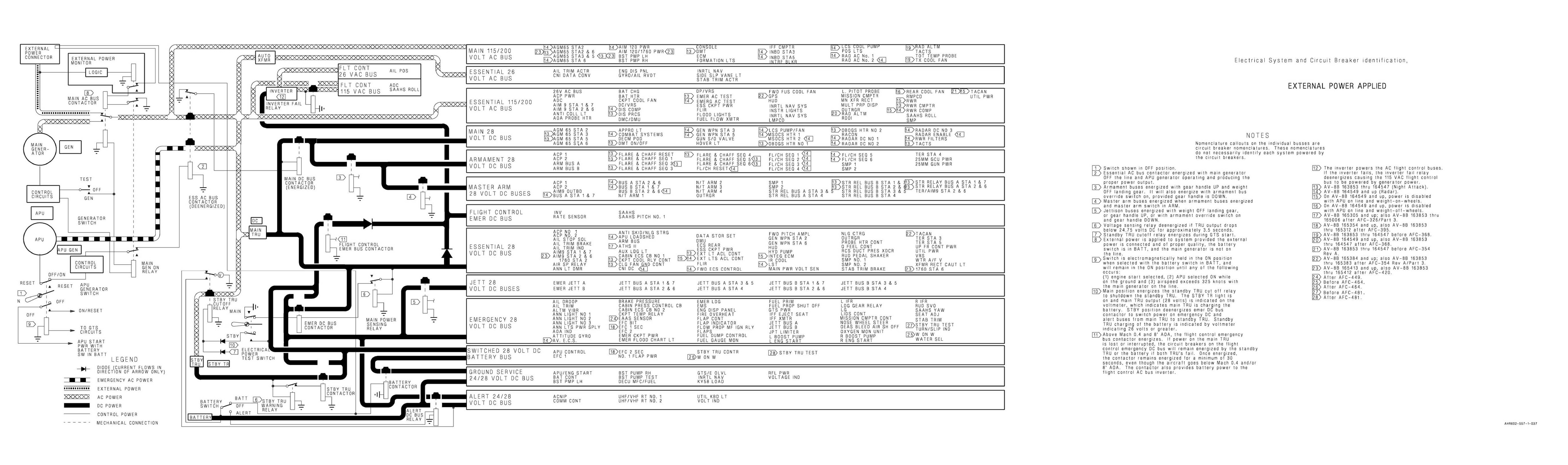
A1-AV8BB-NFM-000
Electrical System, AV-8B 163853 And Up
ORIGINAL
FO-7 (Reverse Blank)
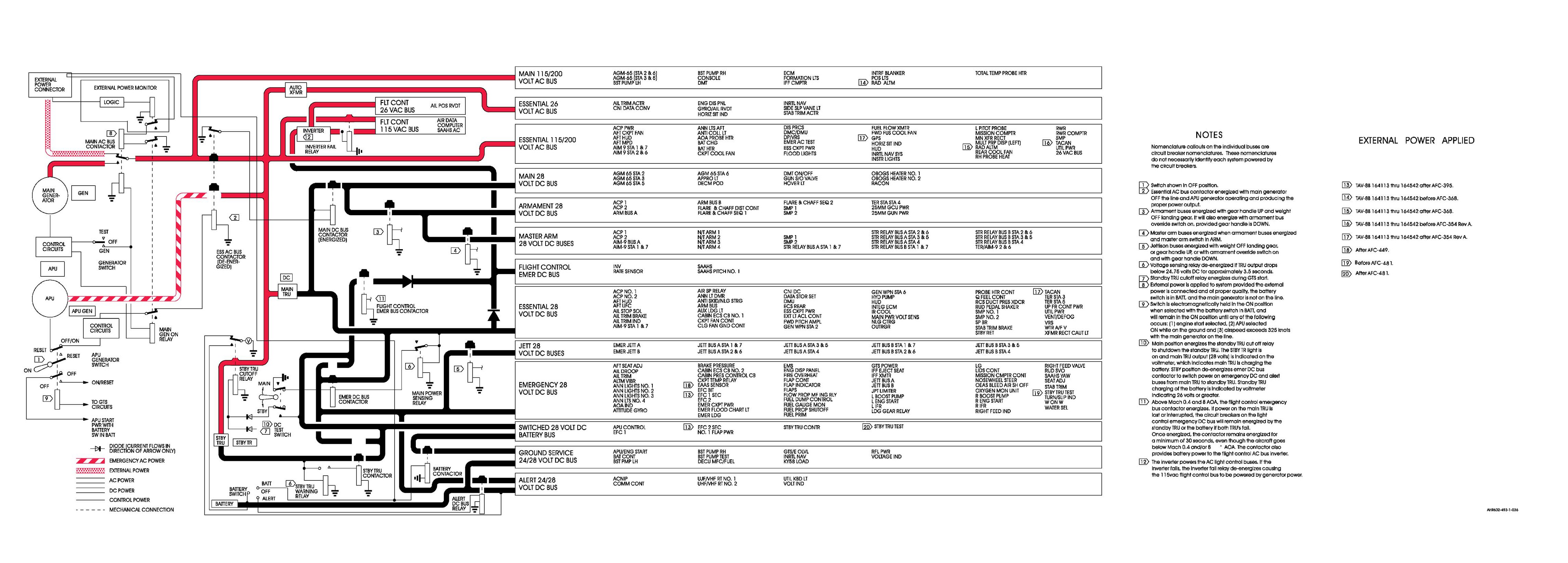
A1-AV8BB-NFM-000
Electrical System, TAV-8B 164113 And Up
ORIGINAL
FO-8 (Reverse Blank)
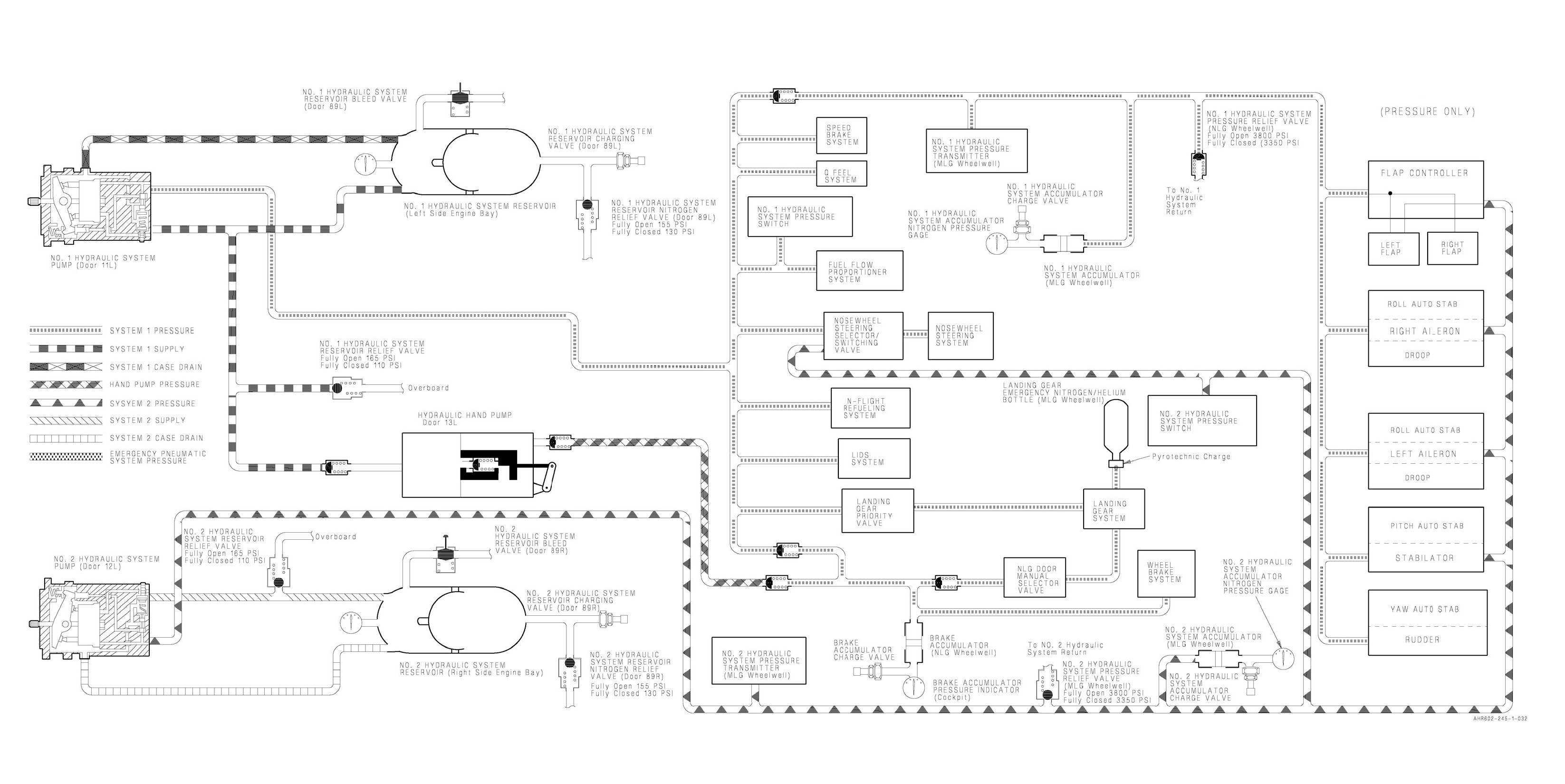
A1-AV8BB-NFM-000
Hydraulic System (Pressure Only)
ORIGINAL
FO-9 (Reverse Blank)
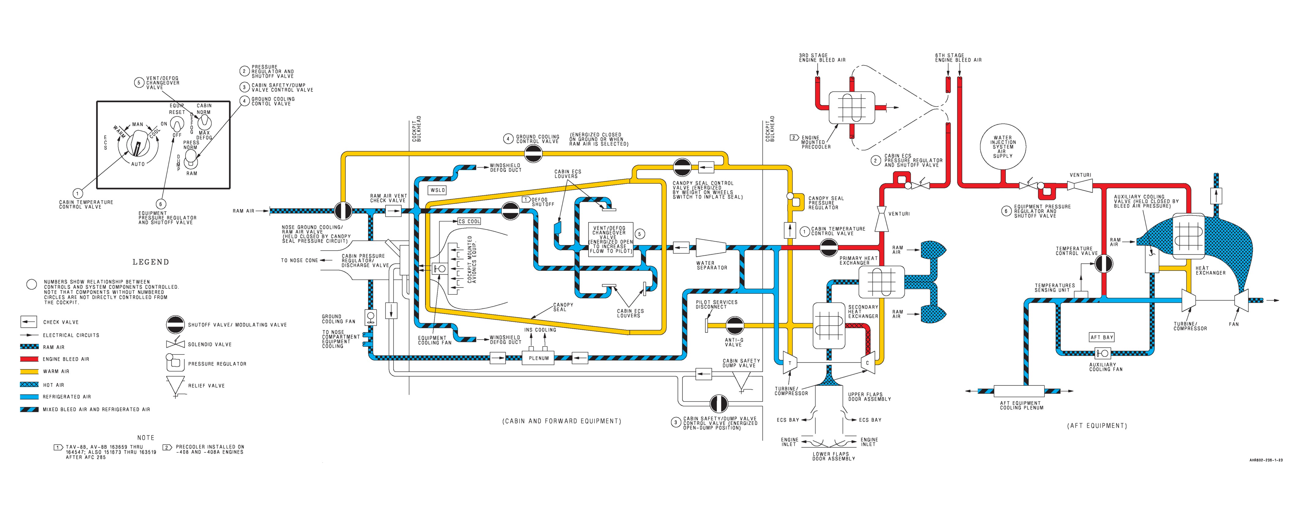
A1-AV8BB-NFM-000
Environmental Control System, TAV-8B, AV-8B 161573 Thru 164547
ORIGINAL
FO-10 (Reverse Blank)
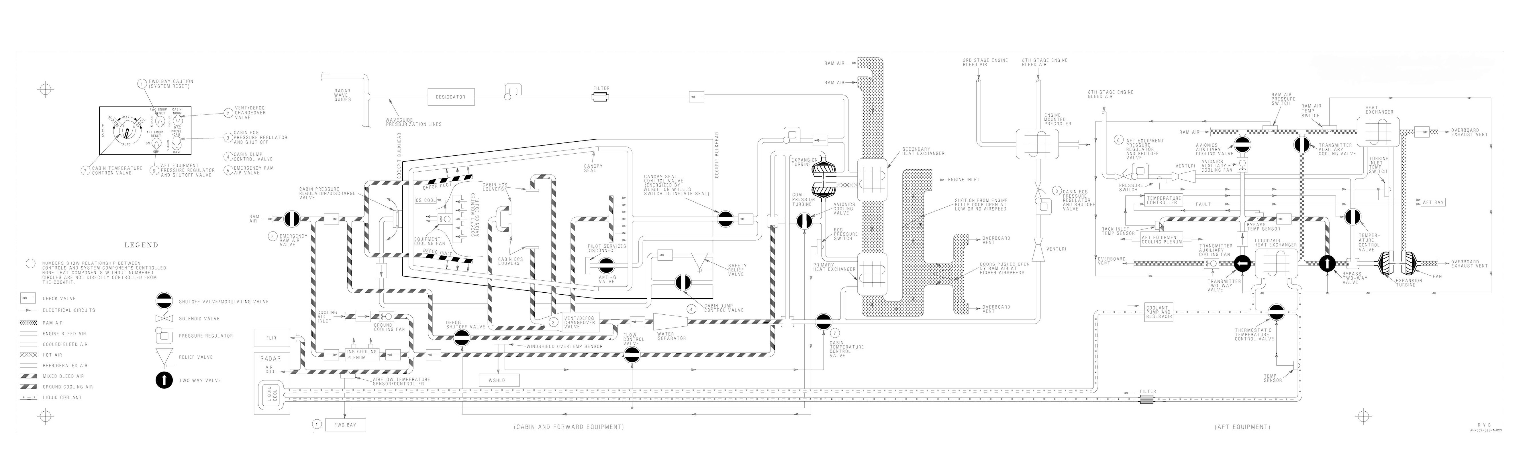
A1-AV8BB-NFM-000
Environmental Control System, AV-8B 164549 And Up
ORIGINAL
FO-11 (Reverse Blank)
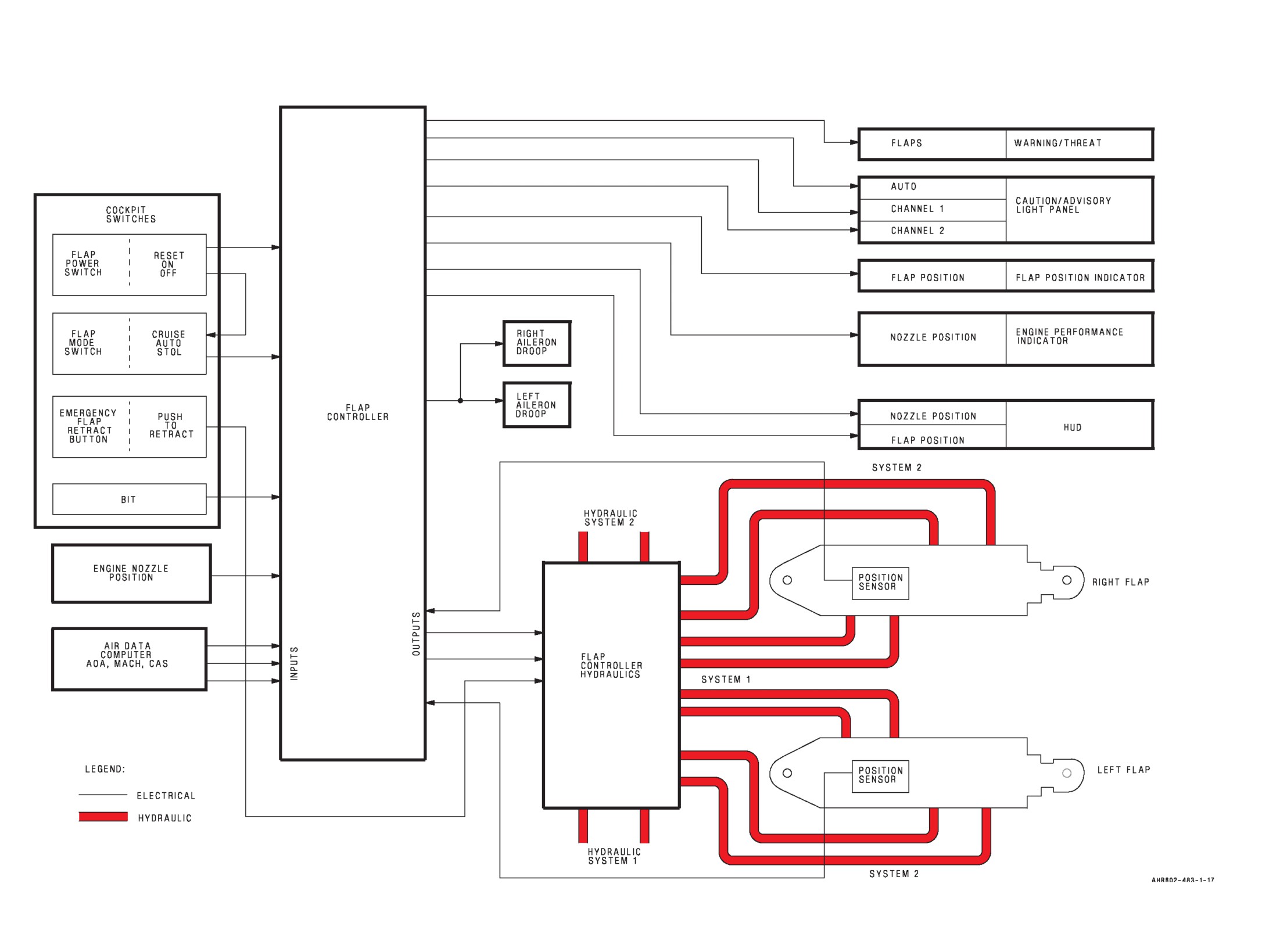
A1-AV8BB-NFM-000
Flap System
ORIGINAL
FO-12 (Reverse Blank)
A1-AV8BC-410-100
1 February 1990
Change 7 - 15 May 2004
TECHNICAL MANUAL
ORGANIZATIONAL MAINTENANCE
PRINCIPLES OF OPERATION
ENVIRONMENTAL CONTROL SYSTEM
NAVY MODEL
TAV-8B
162747 AND UP
DISTRIBUTION STATEMENT C. Distribution authorized to U.S. Government agencies
and their contractors to protect publications required for official use or for
administrative or operational purposes only, determined on 15 May 1999. Other
requests for this document shall be referred to Commanding Officer, Naval Air
Technical Data and Engineering Service Command, Naval Air Station North Island
P.O. Box 357031, Building 90 Distribution, San Diego, CA 92135-7031.
DESTRUCTION NOTICE - For unclassified, limited documents, destroy by any method
that will prevent disclosure of contents or reconstruction of the document.
Published by Direction of the
Commander, Naval Air Systems Command
0801LP1033202
NATEC ELECTRONIC MANUAL
A1-AV8BC-410-100
Change 7 - 15 May 2004
Page A
NUMERICAL INDEX OF EFFECTIVE WORK PACKAGES/PAGES
List of Current Changes
Original
0
1 Feb 90
Change
1
1 Dec 91
Change
2
1 Jan 95
Change
3
1 Mar 97
Change
4
15 May 99
Change
5
1 Oct 99
Change
6
15 Jun 03
Change
7
15 May 04
Only those work packages/pages assigned to the manual are listed in this index. Insert Change 7, dated 15 May 2004. Dispose of
superseded work packages/pages. Superseded classified work packages/pages shall be destroyed in accordance with applicable security
regulations. If changed pages are issued to a work package, insert the changed pages in the applicable work package. The portion of text
affected in a change or revision is indicated by change bars or the change symbol “R” in the outer margin of each column of text.
Changes to illustrations are indicated by pointing hands, change bars, or MAJOR CHANGE symbols. Changes to diagrams may be
indicated by shaded borders.
Total number of pages in this manual is 216 consisting of the following:
WP/Page
Change
WP/Page
Change
WP/Page
Change
WP/Page
Change
Number
Number
Number
Number
Number
Number
Number
Number
Title
7
24
1
8
7
7
6
A
7
25
0
9
7
8
6
B
7
26
0
10
7
9
6
C b lank
7
27
0
006 00
10
6
TPDR-1
7
28
0
1
7
11
6
TPDR-2 blank
7
29
0
2
7
12
6
001 00
30
2
2A deleted
6
13
6
1
4
31
0
2B deleted
6
14
6
2 blank
4
32
2
3
7
15
6
002 00
33
0
4
6
16
6
1
4
34
0
4A
6
17
6
2
4
35
2
4B blank
6
18
6
3
4
36 blank
2
5
0
19
6
4
4
004 00
6
0
20
7
5
4
1
7
7
0
21
7
6
4
2
0
8
0
22
7
7
4
3
7
9
0
23
7
8
4
4
7
10
0
24
7
9
4
5
0
11
7
25
7
10
4
6
0
12
0
26
7
003 00
7
0
13
7
27
7
1
2
8
0
14 blank
7
28
7
2
0
9
0
007 00
29
7
3
0
10
0
1
7
30
7
4
0
11
0
2
7
31
7
5
0
12
0
2A
7
32
7
6
0
13
0
2B blank
7
33
7
7
0
14
0
3
0
34
7
8
0
15
0
4
0
009 00
9
0
16
0
5
0
1
0
10
0
17
0
6
0
2
0
11
0
18
0
7
0
3
0
12
1
19
0
8
0
4
0
13
2
20
0
9
7
5
0
14
2
21
7
10
0
6
0
15
0
22 blank
7
11
7
7
0
16
0
005 00
12 blank
7
8 blank
0
17
0
1
7
008 00
010 00
18
1
2
7
1
7
1
7
19
0
3
7
2
7
2
7
20
0
4
7
3
7
2A
6
21
1
5
7
4
7
2B blank
6
22
0
6
7
5
6
3
7
23
1
7
7
6
6
4
0
A1-AV8BC-410-100
Change 7 - 15 May 2004
Page B/(C blank)
WP/Page
Change
WP/Page
Change
WP/Page
Change
WP/Page
Change
Number
Number
Number
Number
Number
Number
Number
Number
5
0
6
0
7
0
8
0
9
0
10
0
11
0
12
0
13
0
14
0
15
3
16
0
17
0
18
4
19
7
20
7
21
7
22
7
23
7
24
7
25
7
26
7
27
7
28 blank
7
011 00
1
7
2
7
3
7
4
6
5
6
6
6
7
6
8
7
9
7
10
7
11
7
12
7
13
7
14
7
15
7
16 blank
7
012 00
1
7
2
0
3
0
4
0
5
2
6
0
7
5
8
0
9
0
10
5
11
7
12 blank
7

A1-AV8BC-410-100
TPDR-1
Change 7 - 15 May 2004
(TPDR-2 blank)
LIST OF TECHNICAL PUBLICATION DEFICIENCY REPORTS INCORPORATED
ORGANIZATIONAL MAINTENANCE
PRINCIPLES OF OPERATION
ENVIRONMENTAL CONTROL SYSTEM
This WP supersedes TPDR WP, dated 15 June 2003.
1. Deficiencies identified in this Technical Manual shall be submitted via OPNAV 4790/66 and forwarded to
Defense Contract Management Command/Central Technical Manual Control Unit (DCMC/CTMCU),
McDonnell Douglas Corporation, P.O. Box 516, St. Louis, MO 63166-0516.
2. The TPDRs listed below have been incorporated in this issue.
IDENTIFICATION NUMBER/
LOCATION
QA SEQUENCE NUMBER
NONE
A1-AV8BC-410-100
001 00
Change 4 - 15 May 1999
Page 1/(2 blank)
ALPHABETICAL INDEX
ORGANIZATIONAL MAINTENANCE
PRINCIPLES OF OPERATION
ENVIRONMENTAL CONTROL SYSTEM
This WP supersedes WP001 00, dated 1 March 1997.
WP
Title
Number
Anti-G System
009 00
Cabin Cooling and Defog System
Component Locator
005 00
Description and Operation
004 00
Cabin Pressurization System
006 00
Canopy Seal System
007 00
Environmental Control Systems Orientation
003 00
Forward Avionics Cooling System
008 00
Introduction
002 00
Cockpit Reference
002 00
Content
002 00
Diagrams
002 00
Effectivities
002 00
Manual Issue Date
002 00
Navy (AN) Standard/Common Name Nomenclature
002 00
Purpose
002 00
Record of Applicable Technical Directives
002 00
Requisition and Automatic Distribution of NAVAIR Technical Manuals
002 00
Simplified Schematic Highlights
002 00
Technical Directives
002 00
Technical Publications Deficiency Report (TPDR)
002 00
On-Board Oxygen Generating System
Component Locator
012 00
Description and Operation
011 00
Rear Equipment Cooling System
010 00
A1-AV8BC-410-100
002 00
Change 4 - 15 May 1999
Page 1
INTRODUCTION
ORGANIZATIONAL MAINTENANCE
PRINCIPLES OF OPERATION
ENVIRONMENTAL CONTROL SYSTEM
This WP supersedes WP002 00, dated 1 March 1997.
1. PURPOSE.
DAAS (Defense Automated Address System), or
through the DAAS or NAVSUP web sites. For
2. This manual provides the technician with a
assistance with a MILSTRIP requisition, contact
general understanding of how the various
the Naval Inventory Control Point (NAVICP)
components function in the system.
Publications and Forms Customer Service at DSN
442-2626 or (215) 697-2626, Monday through
Friday, 0700 to 1600 Eastern Time.
3. REQUISITION AND AUTOMATIC
DISTRIBUTION OF NAVAIR TECHNICAL
MANUALS.
7. CONTENT.
4. Procedures to be used by Naval activities and
8. Work packages contain description and operation
other Department of Defense activities requiring
of systems, subsystems, and components. The text
NAVAIR technical manuals are defined in
is supported by component locators, block diagrams
NAVAIR 00-25-100 and NAVAIRINST 5605.5.4A.
and simplified schematics.
5. To automatically receive future changes and
9. COMPONENT LOCATOR. The component
revisions to NAVAIR technical manuals, an activity
locator shows aircraft component location. The
must be established on the Automatic Distribution
illustration shows the technicians view when
Requirements List (ADRL) maintained by the
possible.
Naval Air Technical Data and Engineering Service
Command (NATEC). To become established on the
10. BLOCK DIAGRAMS. Block diagrams consist
ADRL, notify your activity central technical
primarily of blocks connected by lines. These
publications librarian. If your activity does not have
diagrams portray the function of a system or
a library, you may establish your automatic
subsystem.
distribution by contacting the Commanding Officer,
NATEC, Attn: Distribution, NAS North Island,
11. SIMPLIFIED SCHEMATICS. Simplified
Bldg. 90, P.O. Box 357031, San Diego CA
schematics consist primarily of blocks connected by
92135-7031. Annual reconfirmation of these
single lines with limited use of symbols and
requirements is necessary to remain on automatic
pictorial drawings of units. These schematics
distribution. Please use your NATEC assigned
simplify system functions as much as possible. All
account number whenever referring to automatic
schematics are shown with electrical power off,
distribution requirements.
switches in off positions, and relays in deenergized
position unless noted on schematic.
6. If additional or replacement copies of this
manual are required with no attendant changes in
the ADRL, they may be ordered by submitting a
12. SIMPLIFIED SCHEMATIC HIGHLIGHTS.
MILSTRIP requisition in accordance with
NAVSUP 485 to Routing Identifier Code ″NFZ″.
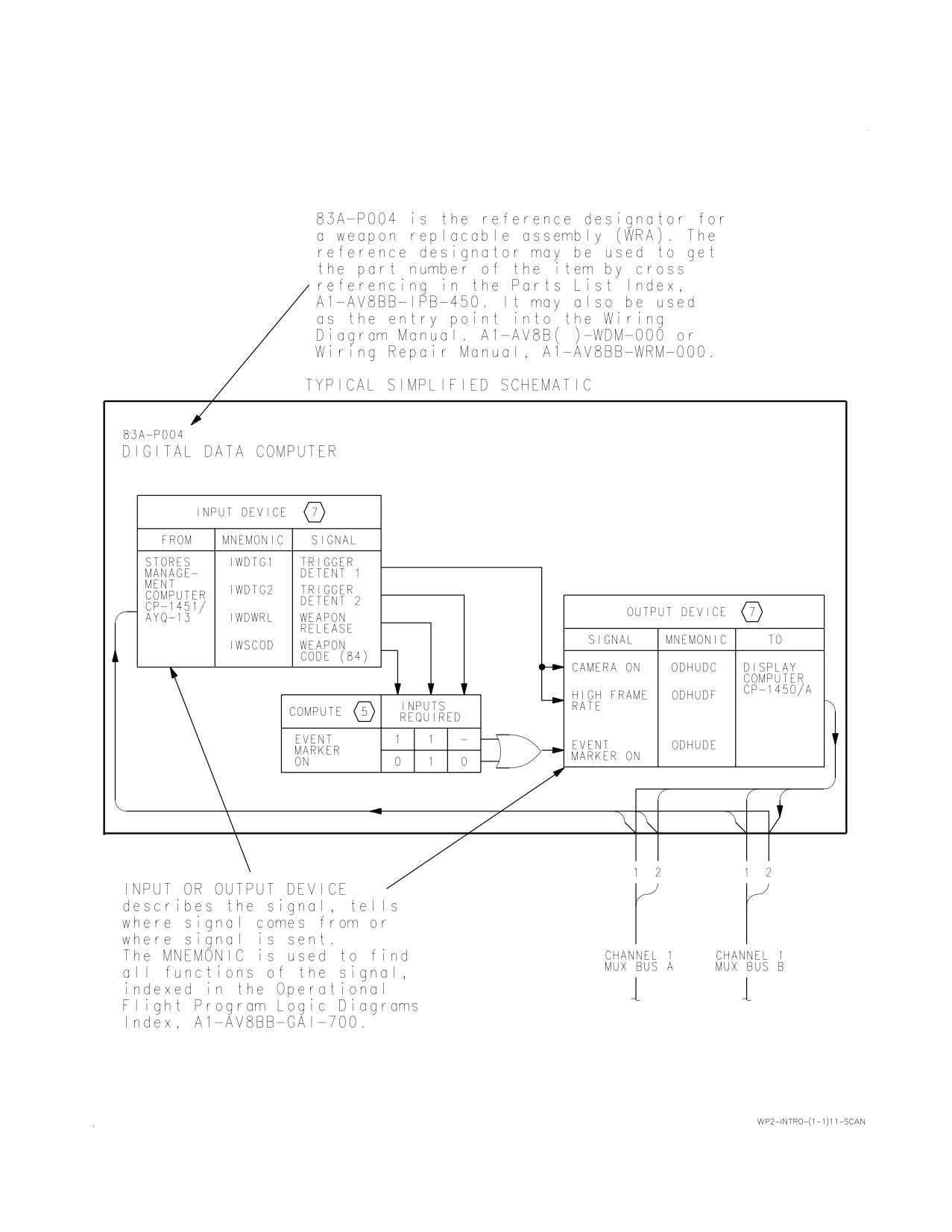
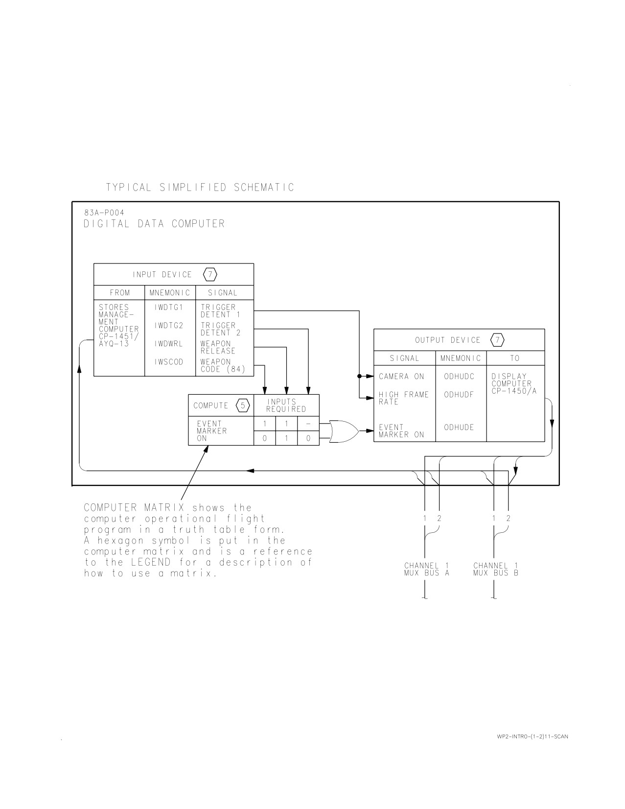
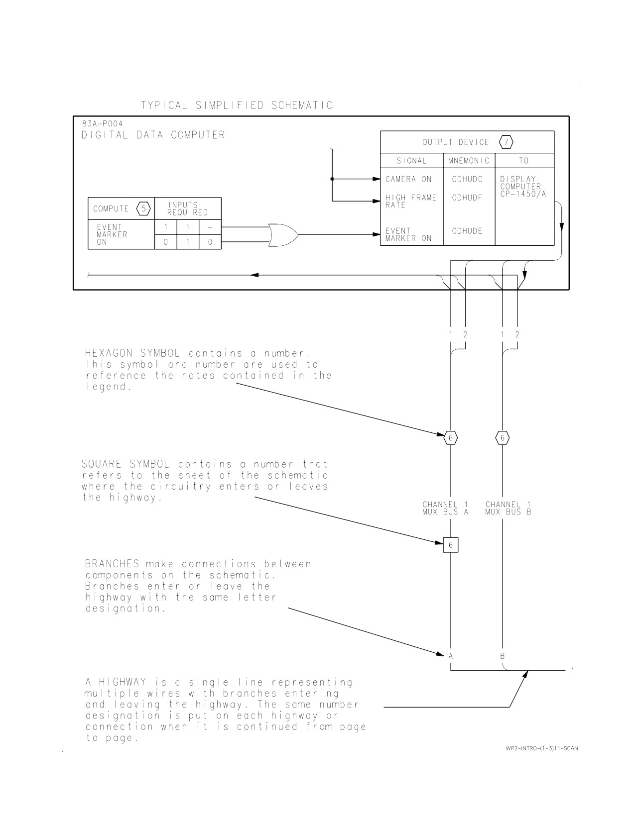
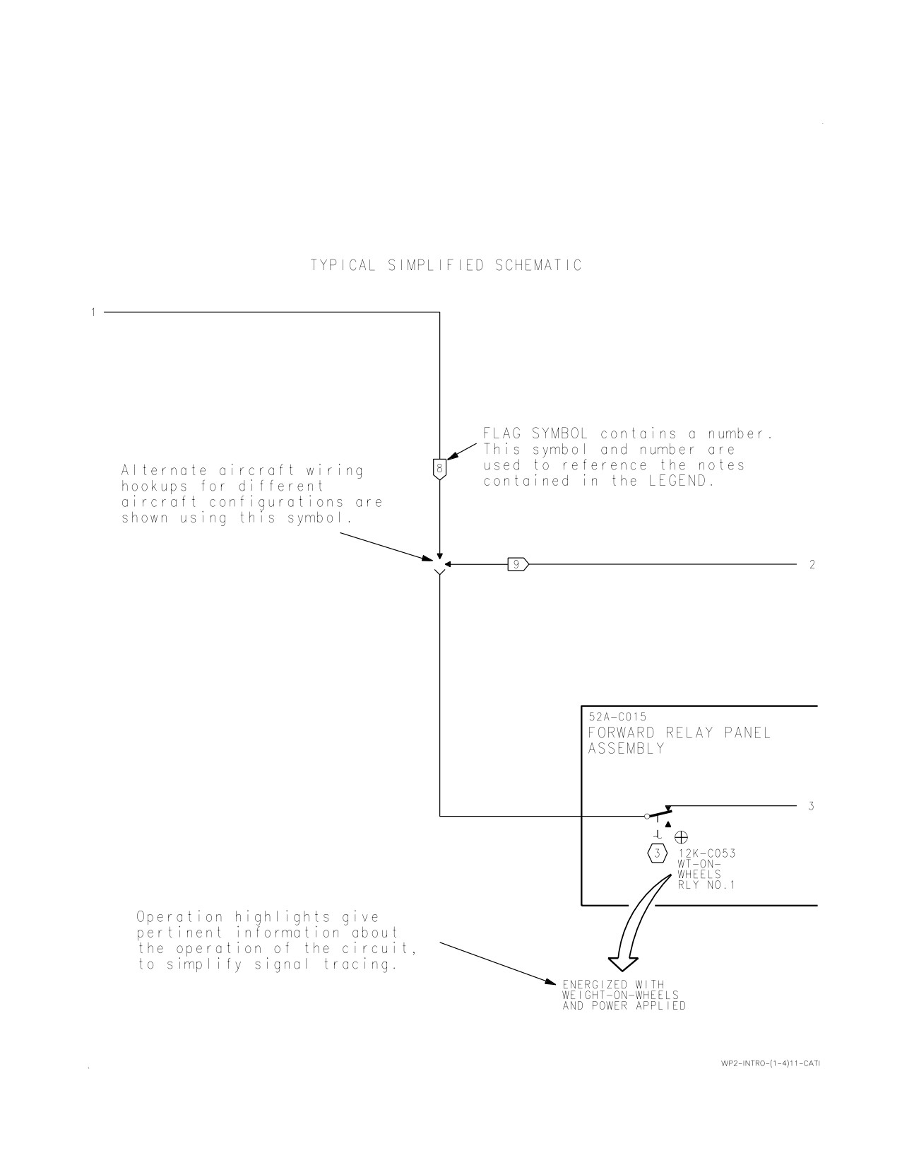
13. For simplified schematic highlights see figure 1.
MILSTRIP requisitions can be submitted through
your supply office, Navy message, or SALTS to
text2/av-8/misc/comwp2/hr6-100C15

A1-AV8BC-410-100
002 00
Change 4
Page
2
14.
MANUAL ISSUE DATE.
the same effectivity as shown on the manual title
page. The effectivity notes may use:
15. The manual issue date on the title page is the
a. Type, model, and series
copy freeze date. No additions, deletions, or changes
are made after the manual issue date, except last
b. Bureau number (tail number)
minute safety of flight or required maintenance
changes. Data collected after the manual issue date
c. Combination of type, model, series, and
will be included in later changes or revisions of the
bureau numbers
manual.
d. Part number or serial number
16. EFFECTIVITIES.
e. Technical directive number
17. Effectivity notes on manual title pages, work
package title pages, and within a work package
f. Configuration/identification number
indicate the aircraft or software program to which
the data applies. If no effectivity note appears on
18. The table below shows examples of effectivity
the work package title page, the work package has
notes and their meanings:
Effectivity Note Examples
Effectivity Note
Definition
AV-8B 162942 AND UP,
Applicable to all AV-8B and TAV-8B for bureau
TAV-8B 162963 AND UP
numbers listed.
AV-8B
Applicable to all AV-8B, but not TAV-8B.
TAV-8B
Applicable to all TAV-8B, but not AV-8B.
AV-8B 161573 THRU 162745
Only applicable to some bureau numbers of AV-8B.
Not applicable to any TAV-8B, even if a TAV-8B is
within the numbers listed.
TAV-8B 162963 AND UP
Only applicable to some bureau numbers of TAV-
8B. Not applicable to any AV-8B, even if an AV-8B
is within the numbers listed.
AV-8B 161573 THRU 162973, TAV-8B 162747
Applicable to aircraft before modification by
THRU 162971 BEFORE AV8AFC-772
technical directive.
AV-8B 163176 AND UP, TAV-8B 163180 AND UP;
Applicable to aircraft modified during production;
ALSO AV-8B 161573 THRU 162973, TAV-8B
also applicable when affected aircraft have been
162747 THRU 162971 AFTER AV8AFC-772
modified by technical directive.
AV-8B 165384 AND UP; ALSO AV-8B 163853
Applicable to aircraft modified during production;
THRU 164547 AFTER AV8AFC-354, AV-8B 164549
also applicable when affected aircraft have been
THRU 165383 AFTER AV8AFC-354 PART 2.
modified by two or more technical directives that
accomplish the same task on different blocks of air-
craft.
AV-8B 161573 THRU 162746 WHEN NO. 2 CON-
Applicable to aircraft if panel P/N XXXX-X is
TROL PANEL P/N XXXX-X IS INSTALLED
installed (Configuration before AVC).

A1-AV8BC-410-100
002 00
Change 4
Page
3
Effectivity Note Examples (Continued)
Effectivity Note
Definition
AV-8B 162942 AND UP, TAV-8B; ALSO AV-8B
Applicable to aircraft modified during production;
161573 THRU 162746 WHEN NO. 2 CONTROL
also applicable to aircraft components modified to
PANEL P/N XXXX-Y (AVC-102) IS INSTALLED
production configuration by technical directive
(configuration after AVC).
P/N 65101-9, 65101-10 & 65105-3
Applicable to assemblies which are interchangeable
between aircraft.
F402-RR-406A, F402-RR-406B,
Applicable to engine models which are interchange-
F402-RR-408 & F402-RR-408A
able between aircraft.
CONFIG/IDENT NUMBER
The CONFIG/IDENT number is the first 4 charac-
88-D (DAY AND TAV-8B)
ters of the operational flight program (OFP) identi-
89-N (NIGHT ATTACK)
fication. The number relates to the software pro-
93-R (RADAR)
gram in a programmable assembly. A1-AV8BB-
96-C (COMBINED NIGHT ATTACK AND
SCM-000, WP003 00 lists the use and applicability
RADAR)
of software programs by OFP IDENT/program load
identification (PLI) number.
19. DEFERRED SPECIFICATION COMPLIANCE
configuration or inspection to delivered aircraft or
CHANGES (DSCC). DSCC control design
aircraft components.
modifications on aircraft TAV-8B 162747. Until the
aircraft is modified, before and after DSCC
22. AIRFRAME CHANGE (AFC) AND AIRBORNE
configurations exist in the manual. Aircraft
SOFTWARE CHANGE (ASC). Technical directives
effectivity may include reference to Engineering Job
which change configuration of aircraft structure or
Sheet (EJS) and blueprint Engineering Order (EO).
equipment installation, i.e. AFC, will list aircraft
Examples of DSCC effectivities are shown below:
bureau numbers in effectivity notes and show
before and after the AFC. Technical directives
a. Before and after configurations for DSCC
which change configuration of operational flight
EJS:
programs (OFP), i.e. ASC, will list the OFP
CONFIG/IDENT NUMBER in effectivity notes
TAV-8B 162747 BEFORE DSCC EJS
and show the latest two authorized OFP programs.
75-0014
See AFC and ASC effectivity examples in
Effectivity Note Example Table.
TAV-8B 162963 AND UP; ALSO TAV-8B
162747 AFTER DSCC EJS 75-0014
23. AIRCRAFT COMPONENT CHANGES. Technical
directives which change configuration of aircraft
b. Before and after configuration for DSCC EO
components, i.e. AAC, ACC, AVC, AYC, and PPC
when no EJS is assigned:
will list part numbers in the effectivities. See AVC
effectivity examples in Effectivity Note Examples
TAV-8B 162747 BEFORE DSCC EO
table.
047626/75A787012
24. RECORD OF APPLICABLE TECHNICAL
TAV-8B 162963 AND UP; ALSO TAV-8B
DIRECTIVES.
162747 AFTER DSCC EO 047626/75A787012
25. The technical directives affecting this manual
20. TECHNICAL DIRECTIVES.
are listed in the Record of Applicable Technical
Directives of each affected work package. Because
21. Technical directives are documents which direct
an ASC directs all aircraft be modified within 30
the accomplishment and recording of a retrofit
days, ASC’s are not listed. When all affected
A1-AV8BC-410-100
002 00
Change 4
Page 4
aircraft are modified, the before configuration is
the technical manuals. Reporting procedures are in
removed from the manual, and the technical
OPNAVINST 4790.2 SERIES.
directive entry is removed from the Record of
Applicable Technical Directives.
30. DIAGRAMS.
31. Simplified schematics and block diagrams are in
26. COCKPIT REFERENCE.
this manual. System schematics are in
A1-AV8B( )-( )-500 series manuals.
27. In this manual, when referring to the AV-8B
cockpit or TAV-8B forward cockpit, cockpit will be
32. NAVY (AN) STANDARD/COMMON
used. When referring to the TAV-8B rear cockpit,
NAME NOMENCLATURE.
rear cockpit will be used.
33. When an item has both Navy (AN) standard
28. TECHNICAL PUBLICATIONS
and common name nomenclature assigned, the
DEFICIENCY REPORT (TPDR).
common name nomenclature will be used in text
and on illustrations. Full Navy (AN) standard
29. The TPDR (OPNAV FORM 4790/66) is the
nomenclature will be used in the Illustrated Parts
form for reporting errors and suspected omissions in
Breakdown (IPB).
A1-AV8BC-410-100
002 00
Change 4
Page 5
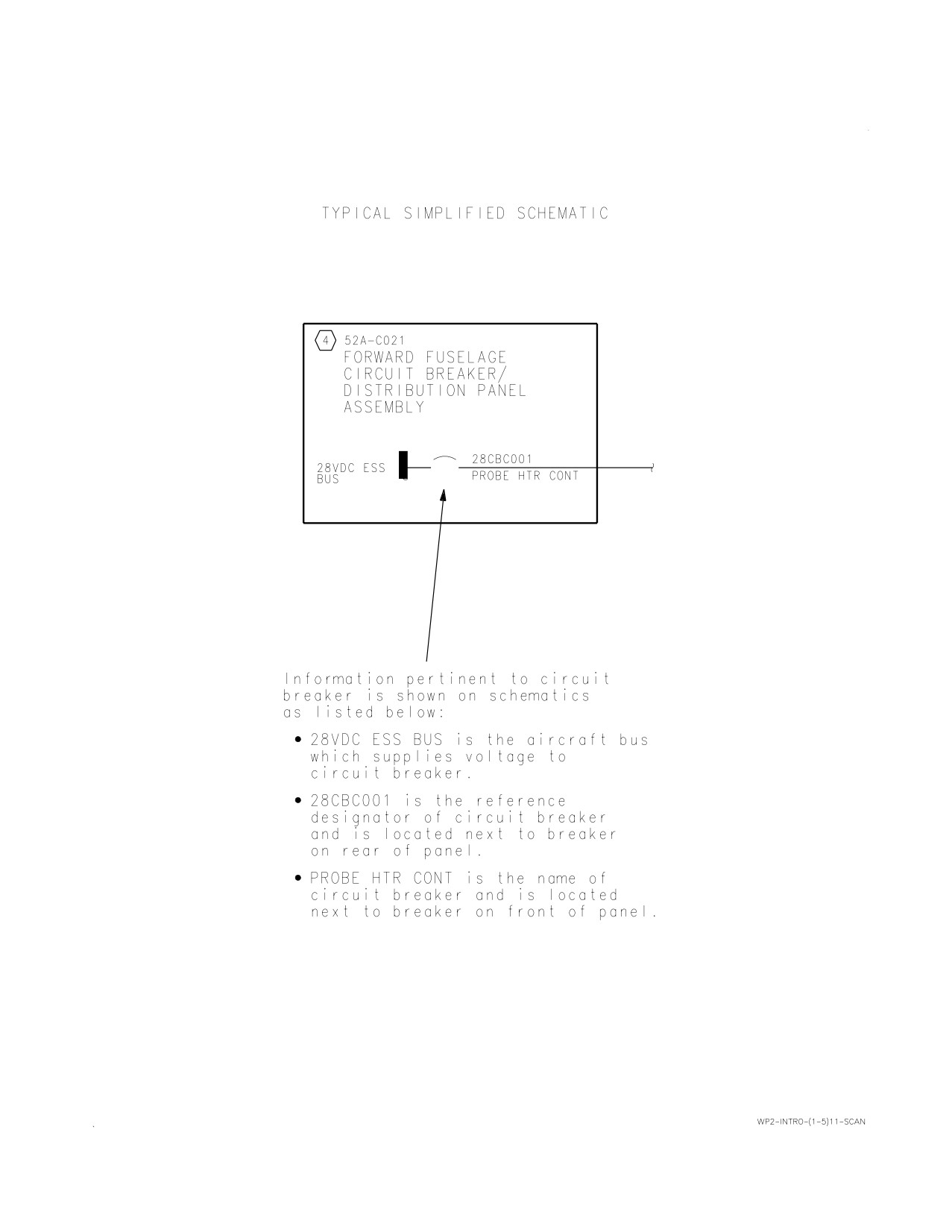
Figure 1. Simplified Schematic Highlights (Sheet 1)
A1-AV8BC-410-100
002 00
Change 4
Page 6
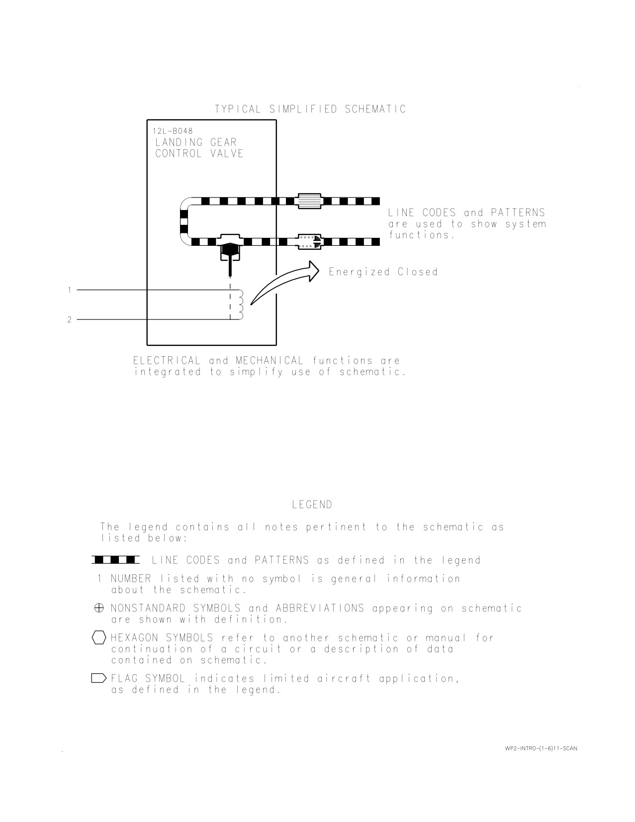
Figure 1. Simplified Schematic Highlights (Sheet 2)
A1-AV8BC-410-100
002 00
Change 4
Page 7
Figure 1. Simplified Schematic Highlights (Sheet 3)
A1-AV8BC-410-100
002 00
Change 4
Page 8
Figure 1. Simplified Schematic Highlights (Sheet 4)
A1-AV8BC-410-100
002 00
Change 4
Page 9
Figure 1. Simplified Schematic Highlights (Sheet 5)
A1-AV8BC-410-100
002 00
Change 4
Page 10
Figure 1. Simplified Schematic Highlights (Sheet 6)
A1-AV8BC-410-100
003 00
Change 2 - 1 January 1995
Page 1
ORGANIZATIONAL MAINTENANCE
PRINCIPLES OF OPERATION
ENVIRONMENTAL CONTROL SYSTEM ORIENTATION
ENVIRONMENTAL CONTROL SYSTEM
Reference Material
None
Alphabetical Index
Subject
Page No.
Environmental Control System Orientation, Figure 1
2
Forward Fuselage Environmental Control System Flow Diagram, Figure 2
15
On-Board Oxygen Generating System Flow Diagram, Figure 4
30
Rear Equipment Cooling System Flow Diagram, Figure 3
25
Record of Applicable Technical Directives
None
A1-AV8BC-410-100
003 00
Page 2
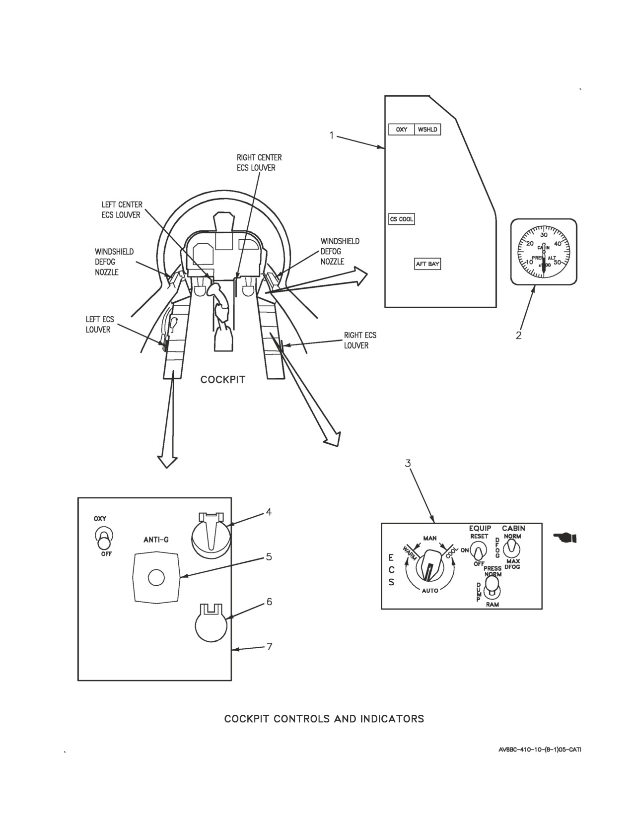
Figure 1. Environmental Control System Orientation (Sheet 1)
A1-AV8BC-410-100
003 00
Page 3
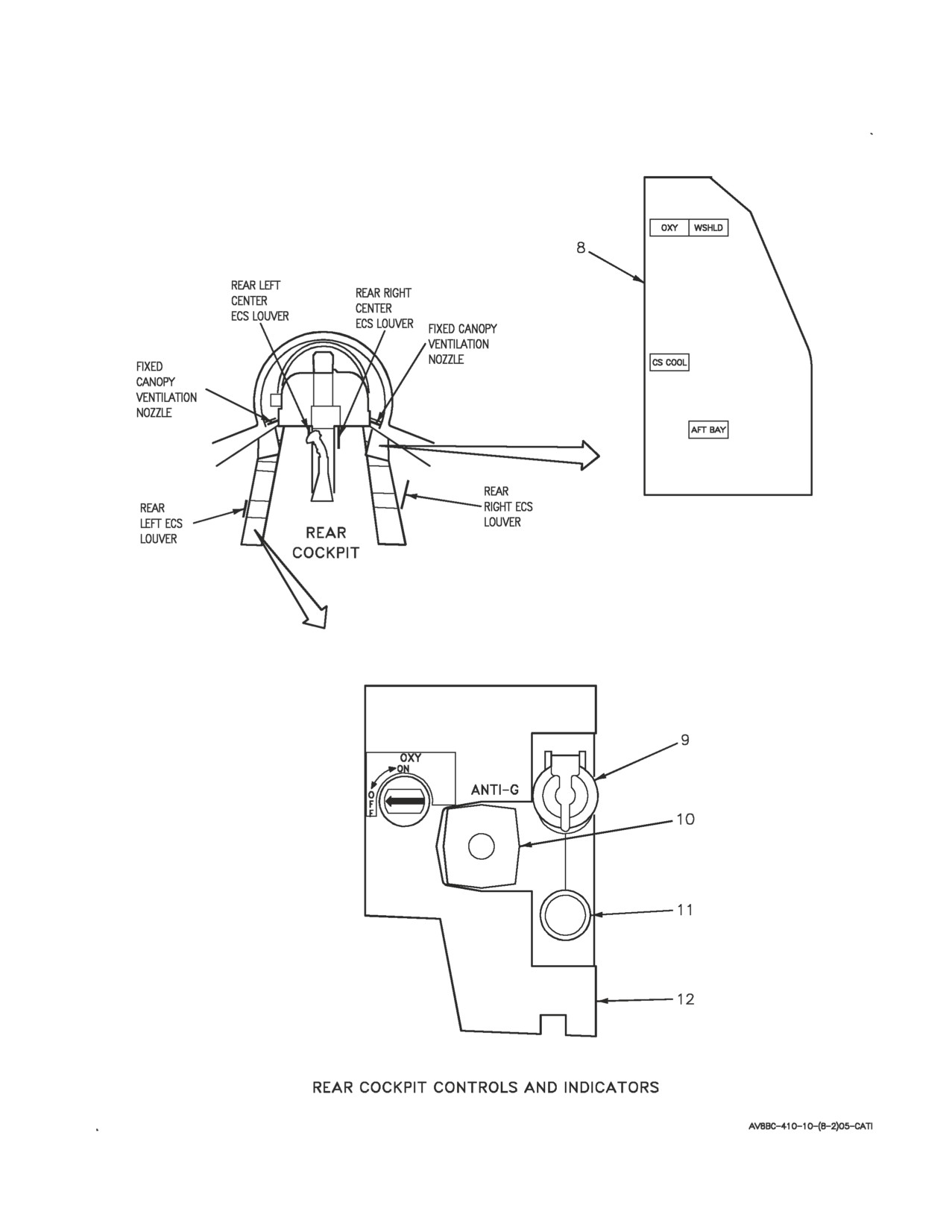
Figure 1. Environmental Control System Orientation (Sheet 2)
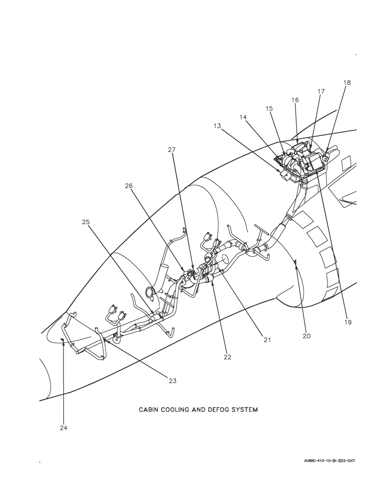
A1-AV8BC-410-100
003 00
Page 4
Figure 1. Environmental Control System Orientation (Sheet 3)
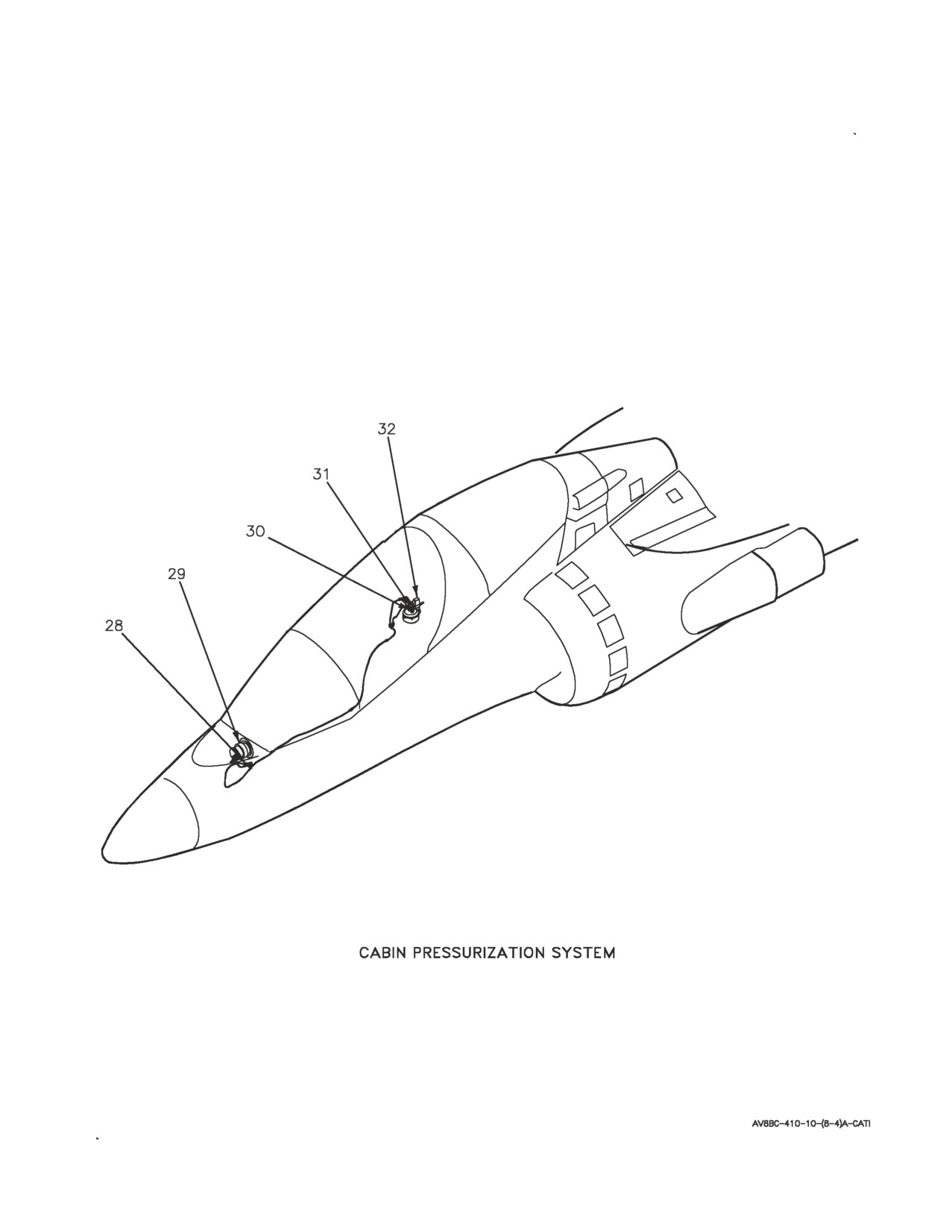
A1-AV8BC-410-100
003 00
Page 5
Figure 1. Environmental Control System Orientation (Sheet 4)
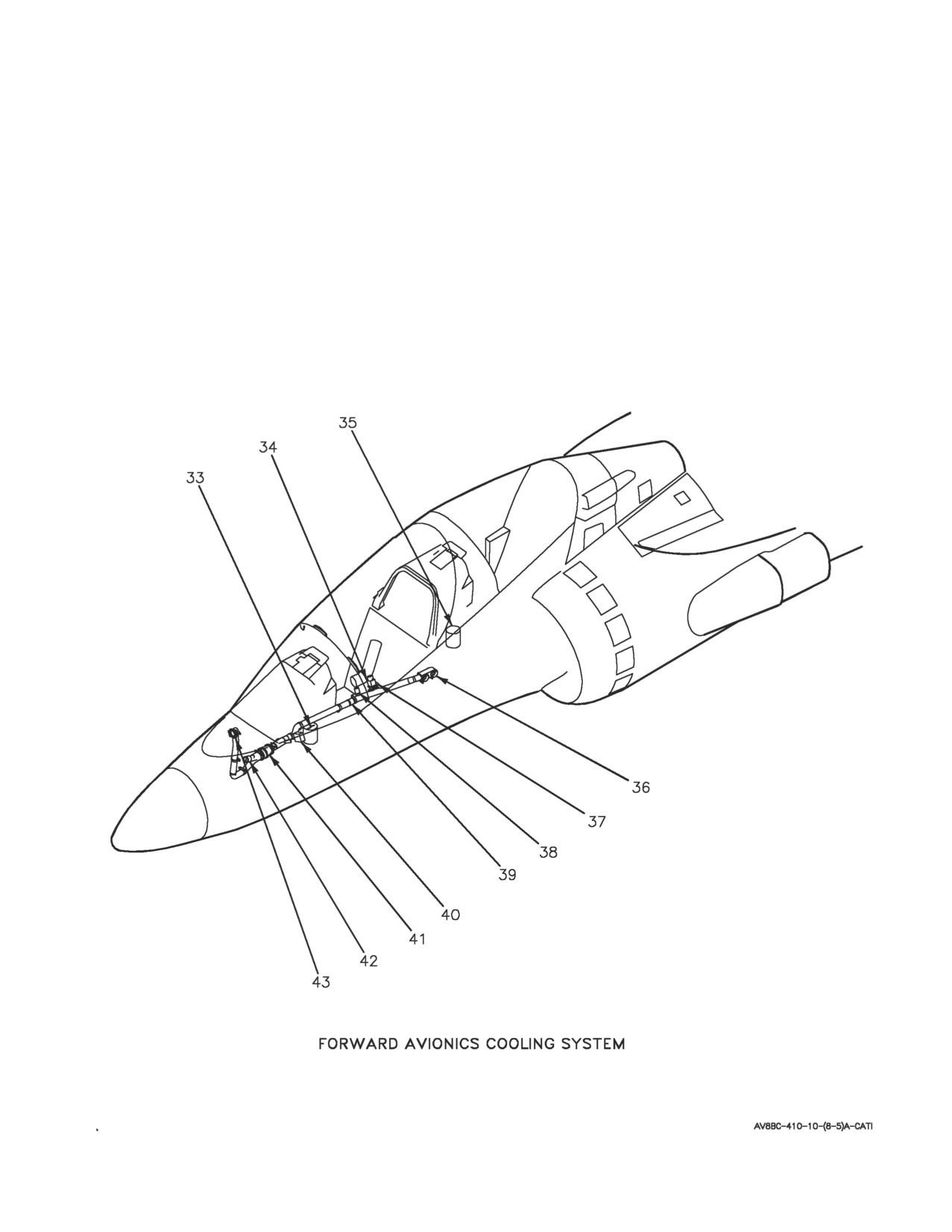
A1-AV8BC-410-100
003 00
Page 6
Figure 1. Environmental Control System Orientation (Sheet 5)
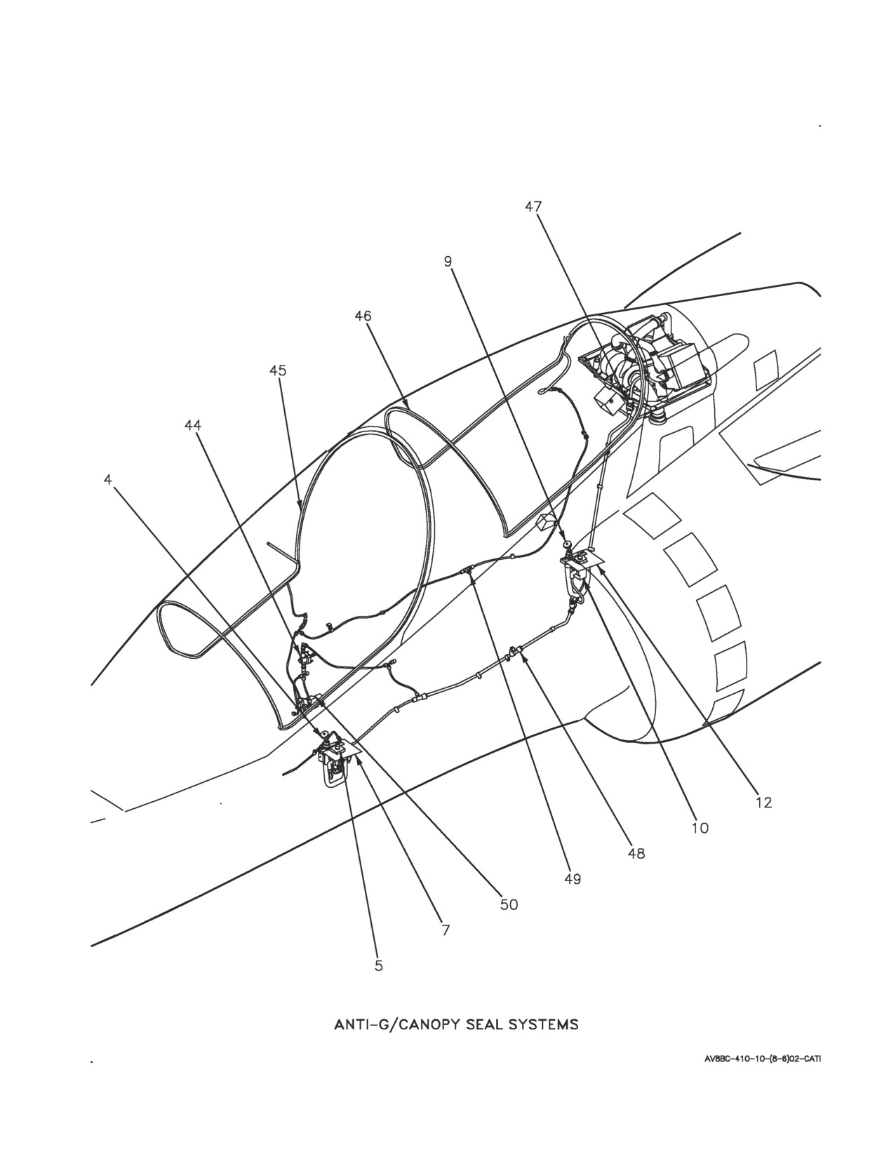
A1-AV8BC-410-100
003 00
Page 7
Figure 1. Environmental Control System Orientation (Sheet 6)
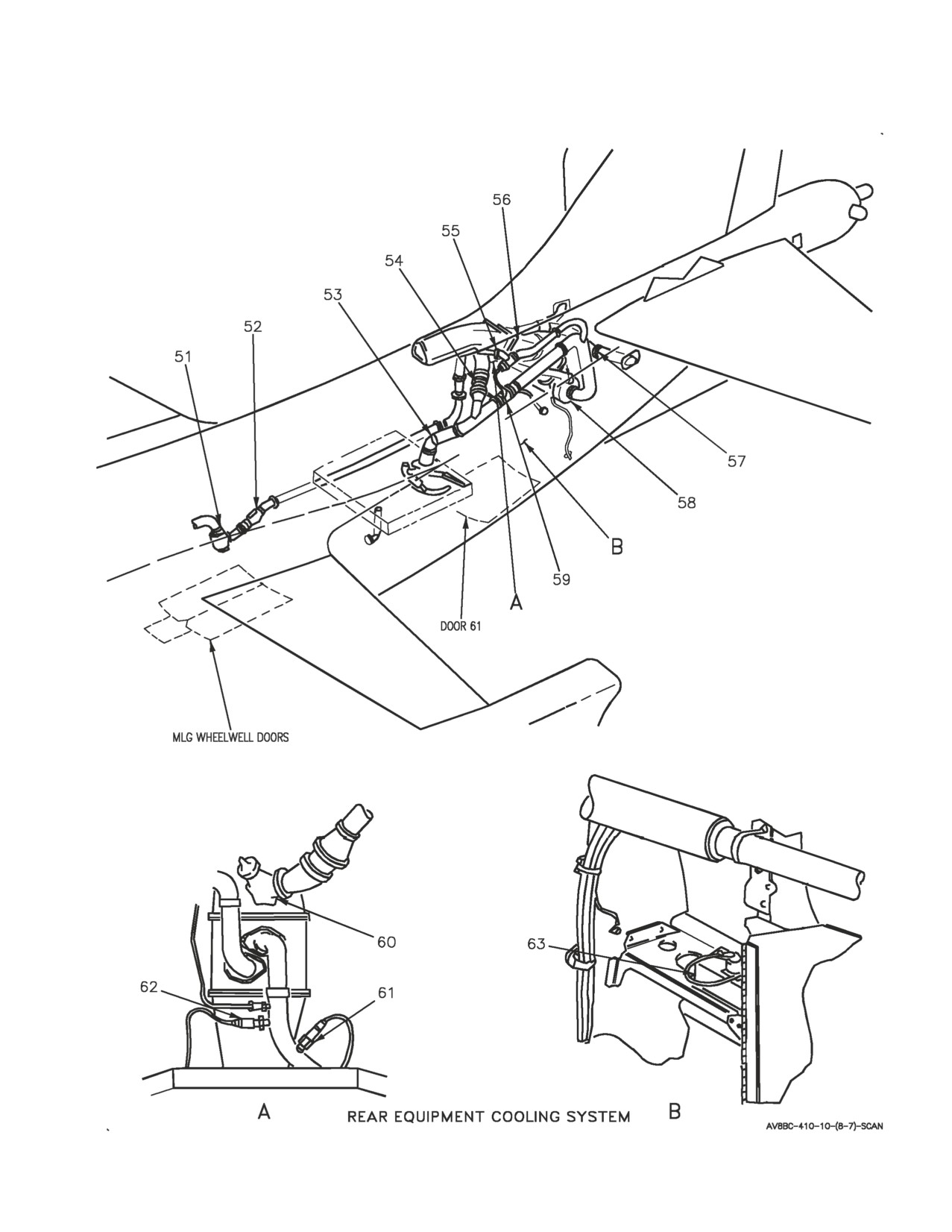
A1-AV8BC-410-100
003 00
Page 8
Figure 1. Environmental Control System Orientation (Sheet 7)
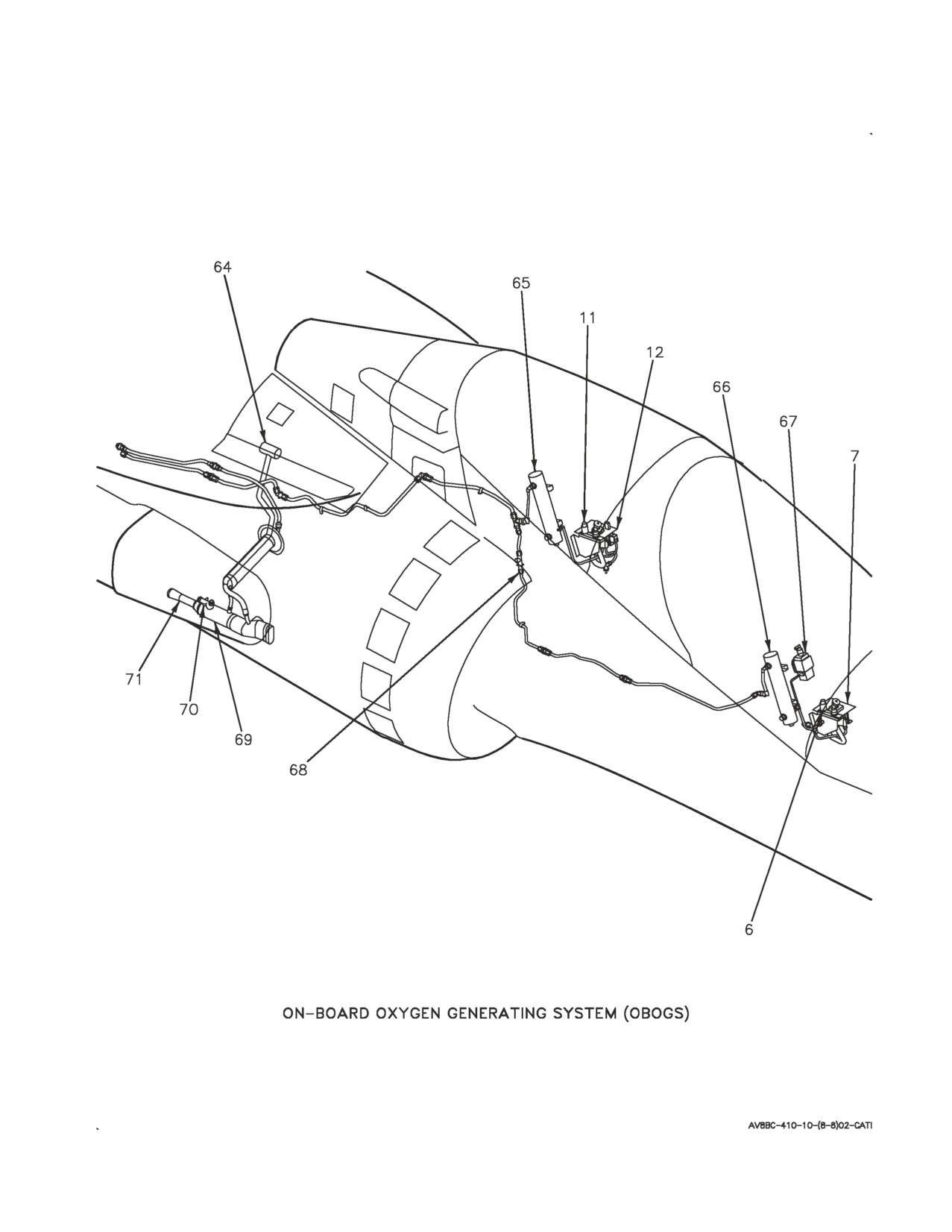
A1-AV8BC-410-100
003 00
Page 9
Figure 1. Environmental Control System Orientation (Sheet 8)
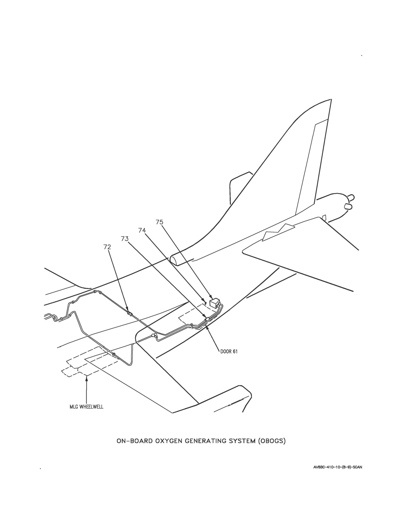
A1-AV8BC-410-100
003 00
Page 10
Figure 1. Environmental Control System Orientation (Sheet 9)

A1-AV8BC-410-100
003 00
Page
11
INDEX
NO
NOMENCLATURE
1
CAUTION/ADVISORY INDICATOR LIGHT ASSEMBLY
AFT BAY CAUTION LIGHT
CS COOL CAUTION LIGHT
OXY CAUTION LIGHT
WSHLD CAUTION LIGHT
2
PRESSURIZED COMPARTMENT ALTIMETER AAU-38/A
3
ECS CONTROL PANEL ASSEMBLY
CABIN SWITCH
CABIN TEMPERATURE CONTROL
EQUIP SWITCH
PRESS SWITCH
4
ANTI-G DISCONNECT
5
ANTI-G VALVE
6
OXYGEN DISCONNECT
7
PILOT SERVICES PANEL ASSEMBLY
OXY SWITCH
8
REAR CAUTION/ADVISORY INDICATOR LIGHT ASSEMBLY
AFT BAY CAUTION LIGHT
CS COOL CAUTION LIGHT
OXY CAUTION LIGHT
WSHLD CAUTION LIGHT
9
REAR ANTI-G DISCONNECT
10
REAR ANTI-G VALVE
11
REAR OXYGEN DISCONNECT
12
REAR PILOT SERVICES PANEL ASSEMBLY
OXY SHUTOFF VALVE
13
TEMPERATURE REGULATING VALVE
14
ECS PRESSURE SWITCH
15
COLD AIR UNIT
16
PRIMARY HEAT EXCHANGER
17
CABIN ECS PRESSURE REGULATING AND SHUTOFF VALVE
18
CABIN ECS AIR FILTER ASSEMBLY
Figure 1. Environmental Control System Orientation
(Sheet
10)

A1-AV8BC-410-100
003 00
Change 1
Page
12
INDEX
NO
NOMENCLATURE
19
SECONDARY HEAT EXCHANGER
20
SKIN TEMPERATURE SENSOR
21
WATER SEPARATOR AND CABIN ECS CHECK VALVE
22
REAR VENT/DEFOG VALVE
23
WINDSHIELD OVERTEMPERATURE SWITCH
24
CABIN TEMPERATURE SENSOR
25
FORWARD VENT/DEFOG VALVE
26
DEFOG SHUTOFF VALVE
27
DUCT TEMPERATURE SENSOR
28
CABIN PRESSURE REGULATOR CHECK VALVE
29
CABIN PRESSURE REGULATOR
30
SAFETY RELIEF VALVE CHECK VALVE
31
SAFETY RELIEF VALVE
32
CABIN DUMP CONTROL VALVE
33
COCKPIT AVIONICS COOLING FAN
34
GROUND COOLING CONTROL VALVE
35
REAR COCKPIT AVIONICS COOLING FAN
1
36
INERTIAL NAVIGATION UNIT CN-1561/ASN-130A COOLING PLENUM ASSEMBLY
2
36
INERTIAL NAVIGATION UNIT CN-1649/ASN-139 COOLING PLENUM ASSEMBLY
37
INS PLENUM CHECK VALVE
38
COCKPIT DIFFERENTIAL PRESSURE SWITCH
39
INS CHECK VALVE
40
SPEED SENSOR
41
GROUND COOLING FAN
42
RAM AIR VENT CHECK VALVE
Figure 1. Environmental Control System Orientation
(Sheet 11)

A1-AV8BC-410-100
003 00
Change 2
Page
13
INDEX
NO
NOMENCLATURE
43
GROUND COOLING VALVE
44
CANOPY SEAL PRESSURE REGULATOR AND CHECK VALVE
45
FORWARD CANOPY PRESSURE SEAL
46
AFT CANOPY PRESSURE SEAL
47
ANTI-G/CANOPY SEAL CHECK VALVE
48
CANOPY SEAL WATER DRAIN VALVE
49
ANTI-G/CANOPY SEAL TEST PORT
50
CANOPY SEAL CONTROL VALVE
51
REAR ECS AIR FILTER ASSEMBLY
52
REAR ECS PRESSURE REDUCING AND SHUTOFF VALVE
53
REAR ECS AIR INLET TEMPERATURE SWITCH
54
REAR ECS GROUND COOLING FAN
55
REAR ECS TEMPERATURE CONTROL VALVE
56
REAR ECS HEAT EXCHANGER
57
REAR ECS CHECK VALVE
58
REAR ECS COLD AIR UNIT
59
REAR ECS TEMPERATURE SENSOR
60
REAR ECS GROUND COOLING VALVE
61
REAR ECS COLD AIR UNIT PRESSURE SWITCH
62
REAR ECS GROUND COOLING FAN PRESSURE SWITCH
63
REAR ECS GROUND COOLING FAN SPEED SENSOR
64
OBOGS BLEED AIR SHUTOFF VALVE
65
REAR OXYGEN PLENUM
66
OXYGEN PLENUM
67
OXYGEN MONITOR ASSEMBLY CRU-91/A
Figure 1. Environmental Control System Orientation
(Sheet
12)

A1-AV8BC-410-100
003 00
Change 2
Page 14
INDEX
NO
NOMENCLATURE
68
OBOGS PRESSURE RELIEF VALVE
69
OBOGS HEAT EXCHANGER
70
OBOGS HEAT EXCHANGER EJECTOR FILTER
71
MIXER/DIFFUSER DUCT
72
OBOGS TEST PORT
73
OBOGS OVERTEMPERATURE SWITCH
74
OBOGS O TEMP INDICATOR
75
OXYGEN CONCENTRATOR GGU-7/A
LEGEND
1
TAV-8B 162747 THRU 164137.
2
TAV-8B 164138 AND UP.
Figure 1. Environmental Control System Orientation
(Sheet 13)
A1-AV8BC-410-100
003 00
Page 15
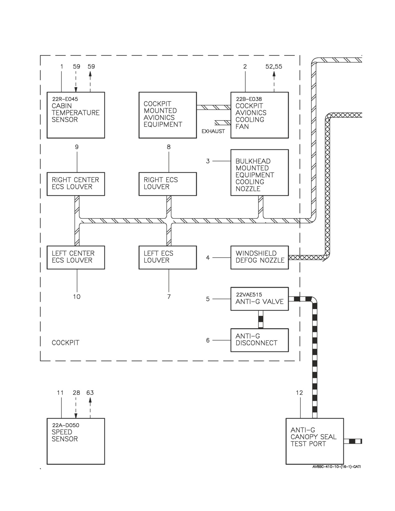
Figure 2. Forward Fuselage Environmental Control System Flow Diagram (Sheet 1)
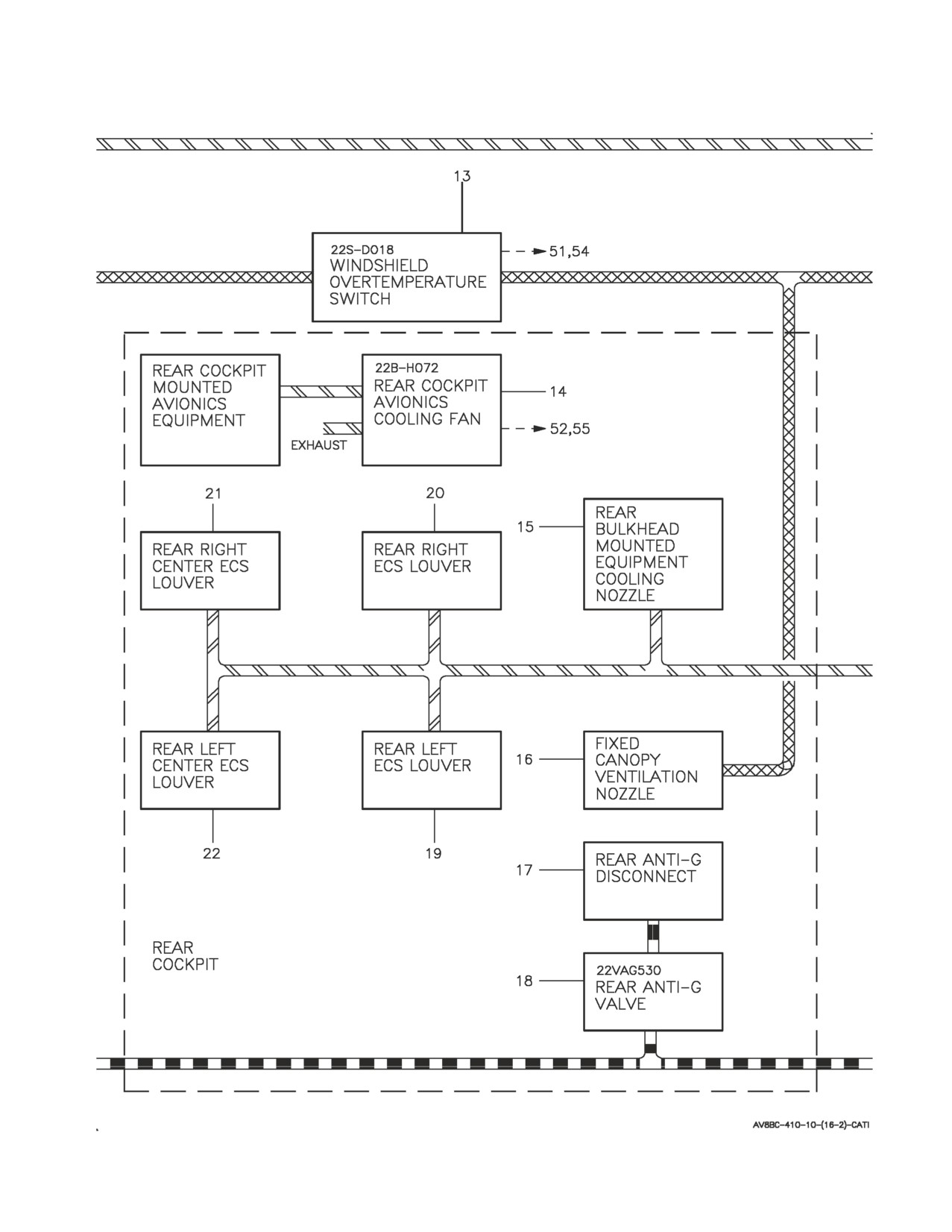
A1-AV8BC-410-100
003 00
Page 16
Figure 2. Forward Fuselage Environmental Control System Flow Diagram (Sheet 2)
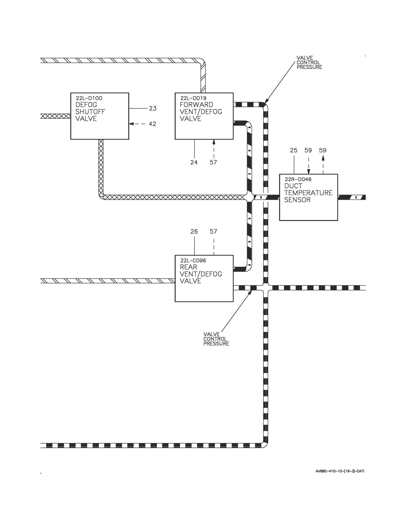
A1-AV8BC-410-100
003 00
Page 17
Figure 2. Forward Fuselage Environmental Control System Flow Diagram (Sheet 3)
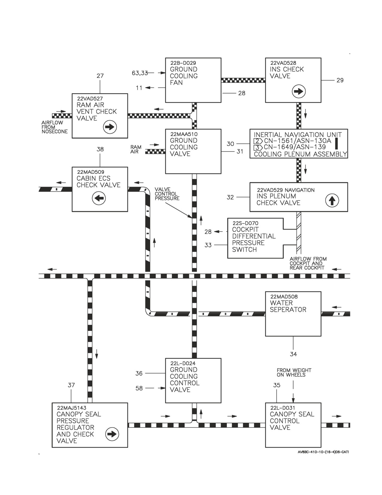
A1-AV8BC-410-100
003 00
Change 1
Page 18
Figure 2. Forward Fuselage Environmental Control System Flow Diagram (Sheet 4)
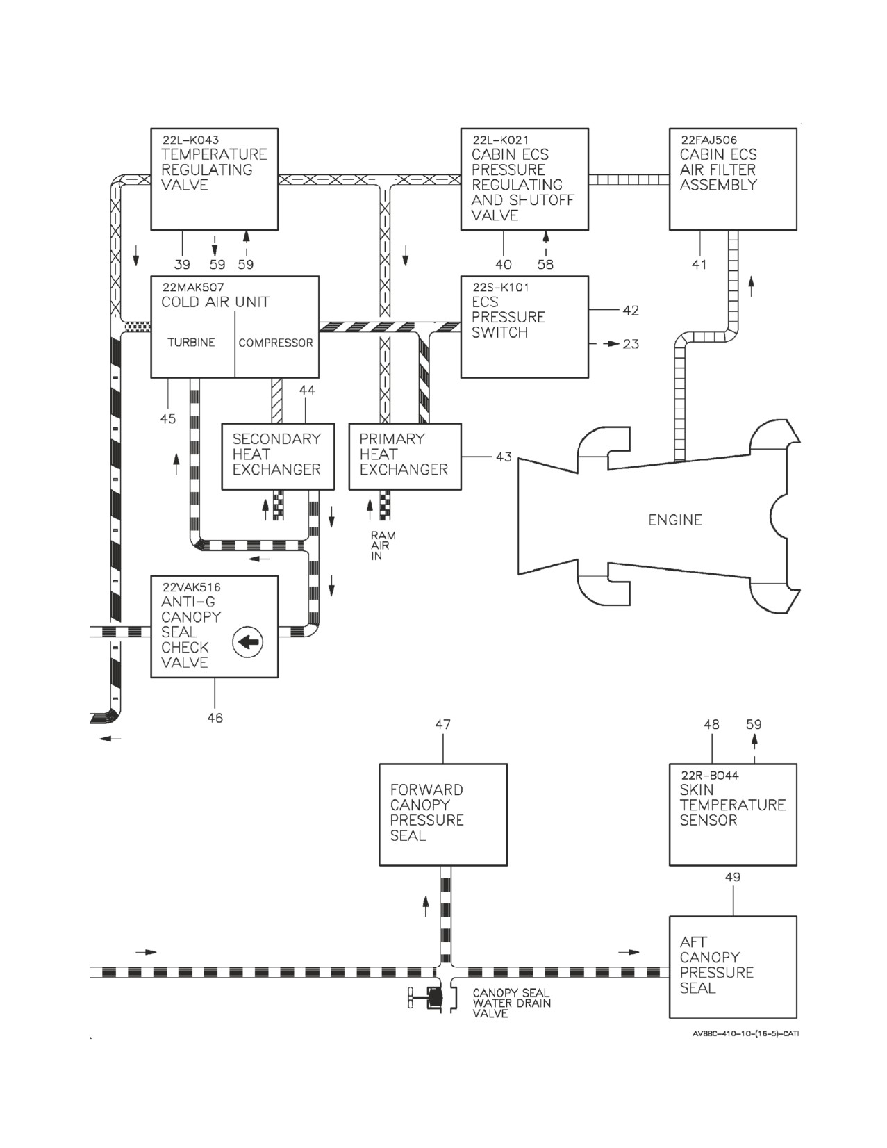
A1-AV8BC-410-100
003 00
Page 19
Figure 2. Forward Fuselage Environmental Control System Flow Diagram (Sheet 5)
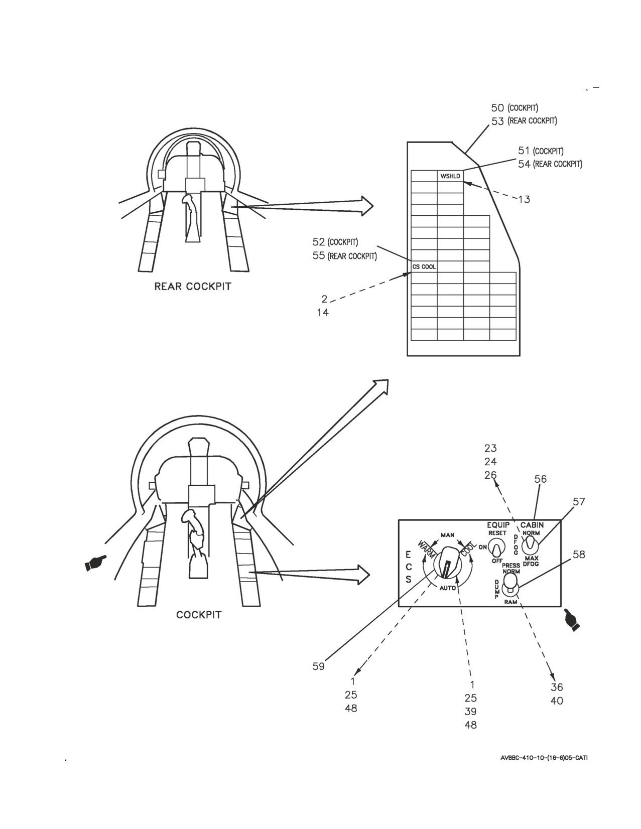
A1-AV8BC-410-100
003 00
Page 20
Figure 2. Forward Fuselage Environmental Control System Flow Diagram (Sheet 6)
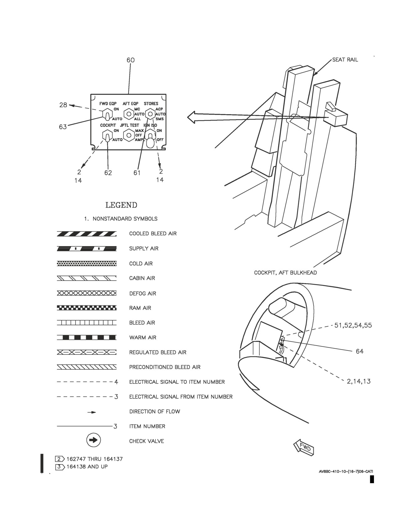
A1-AV8BC-410-100
003 00
Change 1
Page 21
Figure 2. Forward Fuselage Environmental Control System Flow Diagram (Sheet 7)

A1-AV8BC-410-100
003 00
Page
22
ITEM
NO
NOMENCLATURE
1
CABIN TEMPERATURE SENSOR
2
COCKPIT AVIONICS COOLING FAN
3
BULKHEAD MOUNTED EQUIPMENT COOLING NOZZLE
4
WINDSHIELD DEFOG NOZZLE
5
ANTI-G VALVE
6
ANTI-G DISCONNECT
7
LEFT ECS LOUVER
8
RIGHT ECS LOUVER
9
RIGHT CENTER ECS LOUVER
10
LEFT CENTER ECS LOUVER
11
SPEED SENSOR
12
ANTI-G/CANOPY SEAL TEST PORT
13
WINDSHIELD OVERTEMPERATURE SWITCH
14
REAR COCKPIT AVIONICS COOLING FAN
15
REAR BULKHEAD MOUNTED EQUIPMENT COOLING NOZZLE
16
FIXED CANOPY VENTILATION NOZZLE
17
REAR ANTI-G DISCONNECT
18
REAR ANTI-G VALVE
19
REAR LEFT ECS LOUVER
20
REAR RIGHT ECS LOUVER
21
REAR RIGHT CENTER ECS LOUVER
22
REAR LEFT CENTER ECS LOUVER 11
23
DEFOG SHUTOFF VALVE
24
FORWARD VENT/DEFOG VALVE
25
DUCT TEMPERATURE SENSOR
Figure 2. Forward Fuselage Environmental Control System Flow Diagram
(Sheet
8)

A1-AV8BC-410-100
003 00
Change 1
Page
23
ITEM
NO
NOMENCLATURE
26
REAR VENT/DEFOG VALVE
27
RAM AIR VENT CHECK VALVE
28
GROUND COOLING FAN
29
INS CHECK VALVE
2
30
INERTIAL NAVIGATION UNIT CN-1561/ASN-130A COOLING PLENUM ASSEMBLY
3
30
INERTIAL NAVIGATION UNIT CN-1649/ASN-139 COOLING PLENUM ASSEMBLY
31
GROUND COOLING VALVE
32
INS PLENUM CHECK VALVE
33
COCKPIT DIFFERENTIAL PRESSURE SWITCH
34
WATER SEPARATOR
35
CANOPY SEAL CONTROL VALVE
36
GROUND COOLING CONTROL VALVE
37
CANOPY SEAL PRESSURE REGULATOR AND CHECK VALVE
38
CABIN ECS CHECK VALVE
39
TEMPERATURE REGULATING VALVE
40
CABIN ECS PRESSURE REGULATING AND SHUTOFF VALVE
41
CABIN ECS AIR FILTER ASSEMBLY
42
ECS PRESSURE SWITCH
43
PRIMARY HEAT EXCHANGER
44
SECONDARY HEAT EXCHANGER
45
COLD AIR UNIT
46
ANTI-G/CANOPY SEAL CHECK VALVE
47
FORWARD CANOPY PRESSURE SEAL
48
SKIN TEMPERATURE SENSOR
49
AFT CANOPY PRESSURE SEAL
Figure 2. Forward Fuselage Environmental Control System Flow Diagram
(Sheet
9)

A1-AV8BC-410-100
003 00
Change 1
Page
24
ITEM
NO
NOMENCLATURE
50
CAUTION/ADVISORY INDICATOR LIGHT ASSEMBLY
51
WSHLD CAUTION LIGHT
52
CS COOL CAUTION LIGHT
53
REAR CAUTION/ADVISORY INDICATOR LIGHT ASSEMBLY
54
WSHLD CAUTION LIGHT
55
CS COOL CAUTION LIGHT
56
ECS CONTROL PANEL ASSEMBLY
57
CABIN SWITCH
58
PRESS SWITCH
59
CABIN TEMPERATURE CONTROL
60
GROUND POWER PANEL ASSEMBLY
61
STORES SWITCH
62
COCKPIT SWITCH
63
FWD EQP SWITCH
64
ANNUNCIATOR LIGHT CONTROLLER
Figure 2. Forward Fuselage Environmental Control System Flow Diagram (Sheet 10)
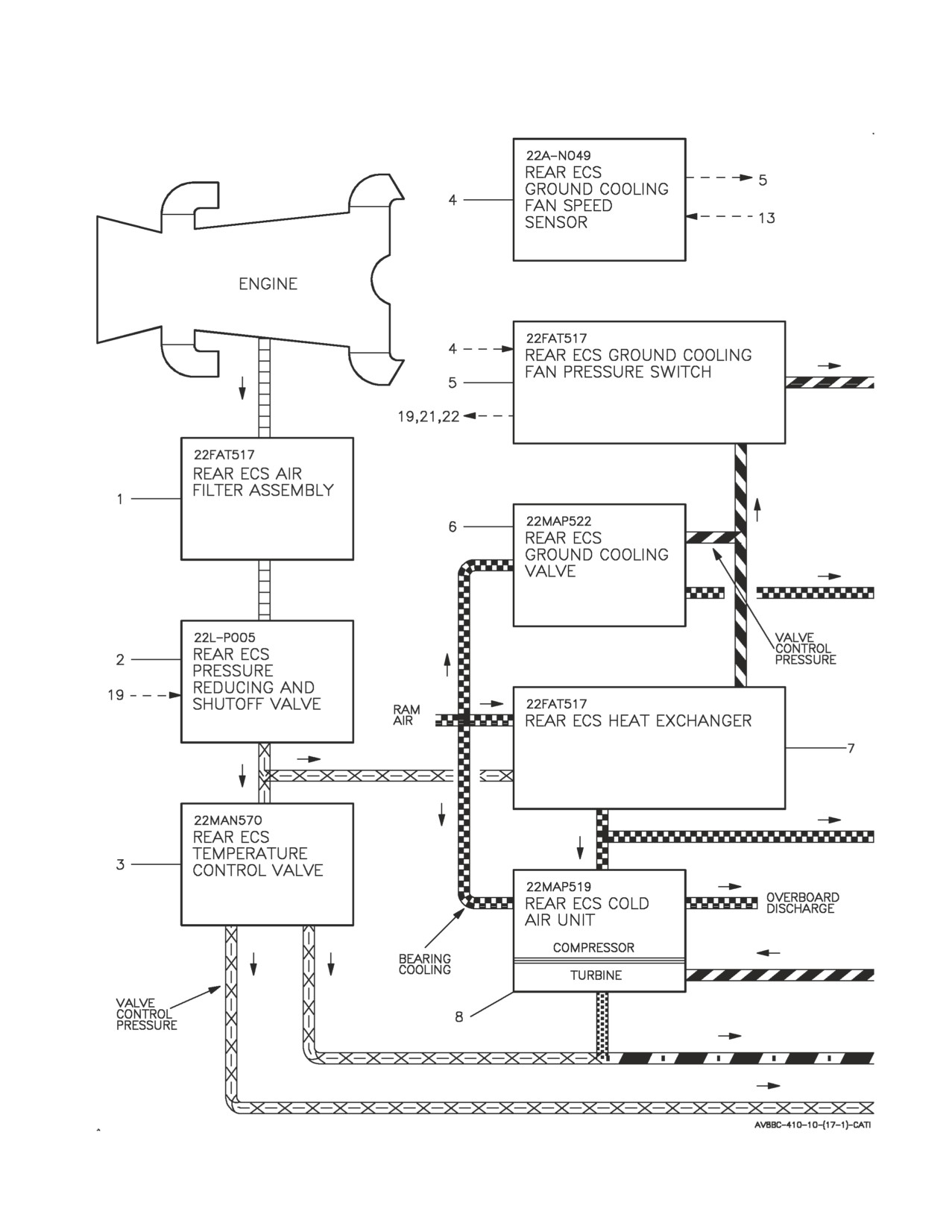
A1-AV8BC-410-100
003 00
Page 25
Figure 3. Rear Equipment Cooling System Flow Diagram (Sheet 1)
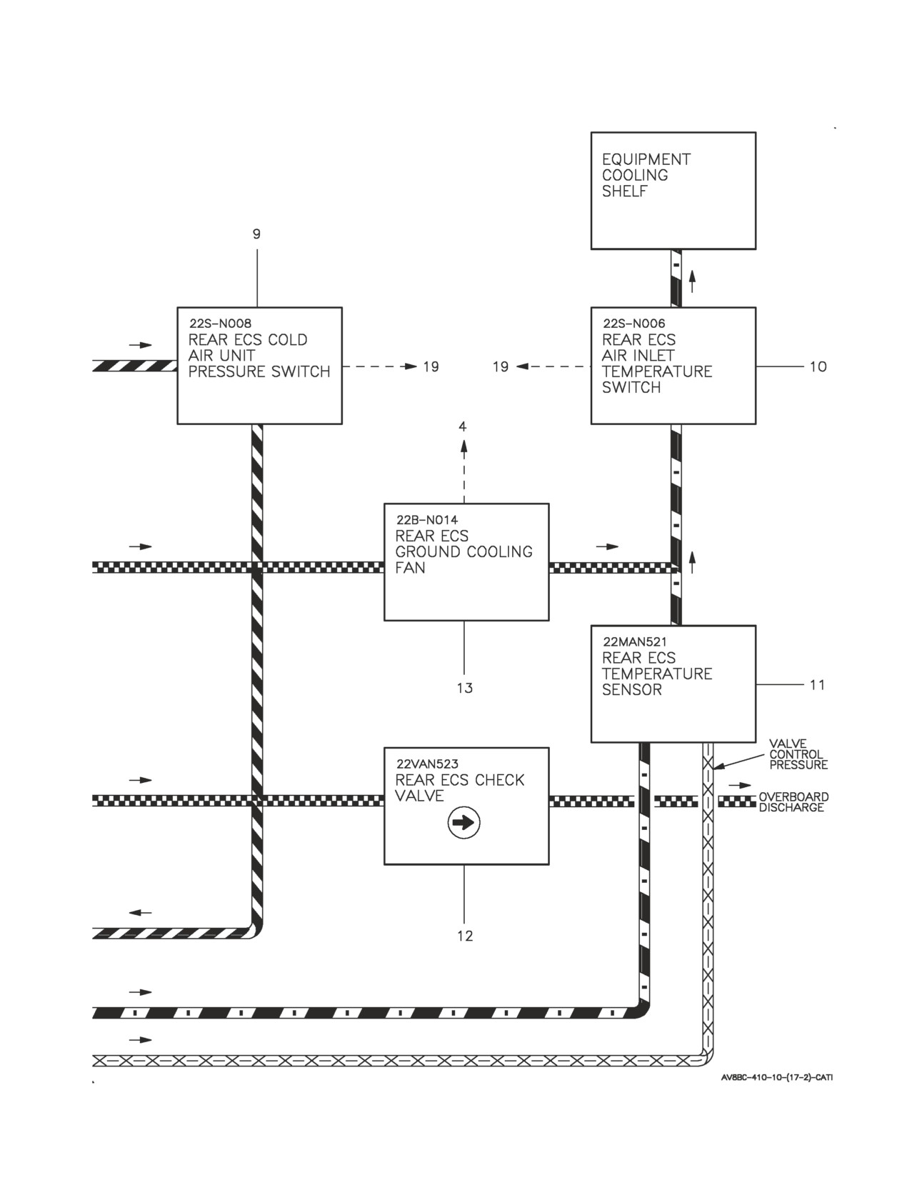
A1-AV8BC-410-100
003 00
Page 26
Figure 3. Rear Equipment Cooling System Flow Diagram (Sheet 2)
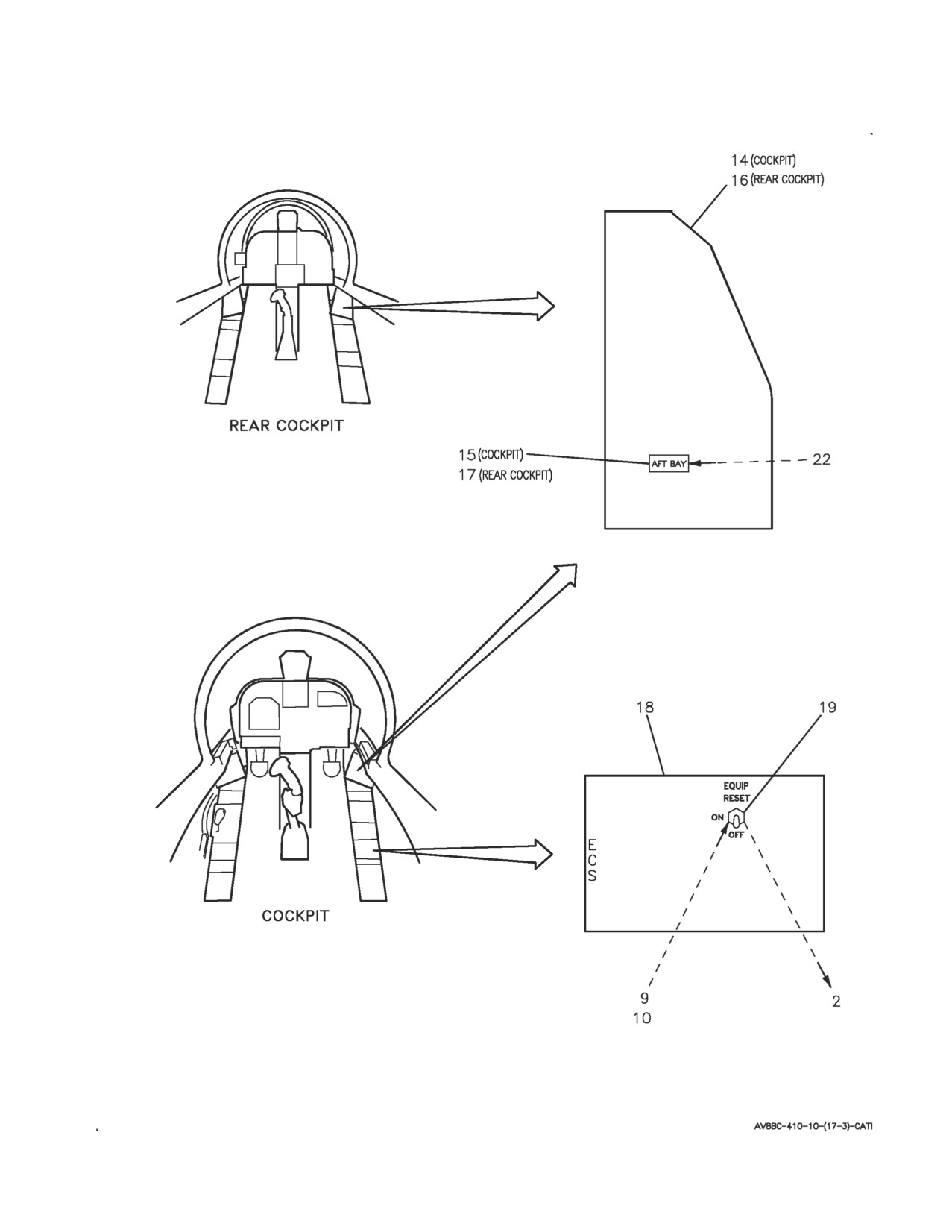
A1-AV8BC-410-100
003 00
Page 27
Figure 3. Rear Equipment Cooling System Flow Diagram (Sheet 3)
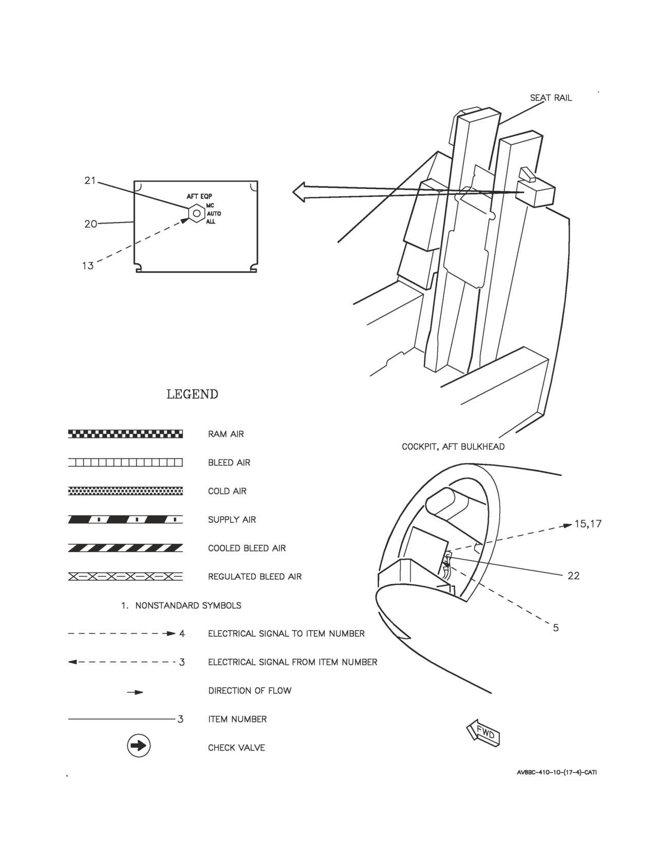
A1-AV8BC-410-100
003 00
Page 28
Figure 3. Rear Equipment Cooling System Flow Diagram (Sheet 4)

A1-AV8BC-410-100
003 00
Page
29
ITEM
NO
NOMENCLATURE
1
REAR ECS AIR FILTER ASSEMBLY
2
REAR ECS PRESSURE REDUCING AND SHUTOFF VALVE
3
REAR ECS TEMPERATURE CONTROL VALVE
4
REAR ECS GROUND COOLING FAN SPEED SENSOR
5
REAR ECS GROUND COOLING FAN PRESSURE SWITCH
6
REAR ECS GROUND COOLING VALVE
7
REAR ECS HEAT EXCHANGER
8
REAR ECS COLD AIR UNIT
9
REAR ECS COLD AIR UNIT PRESSURE SWITCH
10
REAR ECS AIR INLET TEMPERATURE SWITCH
11
REAR ECS TEMPERATURE SENSOR
12
REAR ECS CHECK VALVE
13
REAR ECS GROUND COOLING FAN
14
CAUTION/ADVISORY INDICATOR LIGHT ASSEMBLY
15
AFT BAY CAUTION LIGHT
16
REAR CAUTION/ADVISORY INDICATOR LIGHT ASSEMBLY
17
AFT BAY CAUTION LIGHT
18
ECS CONTROL PANEL ASSEMBLY
19
EQUIP SWITCH
20
GROUND POWER PANEL ASSEMBLY
21
AFT EQP SWITCH
22
ANNUNCIATOR LIGHT CONTROLLER
Figure 3. Rear Equipment Cooling System Flow Diagram
(Sheet 5)
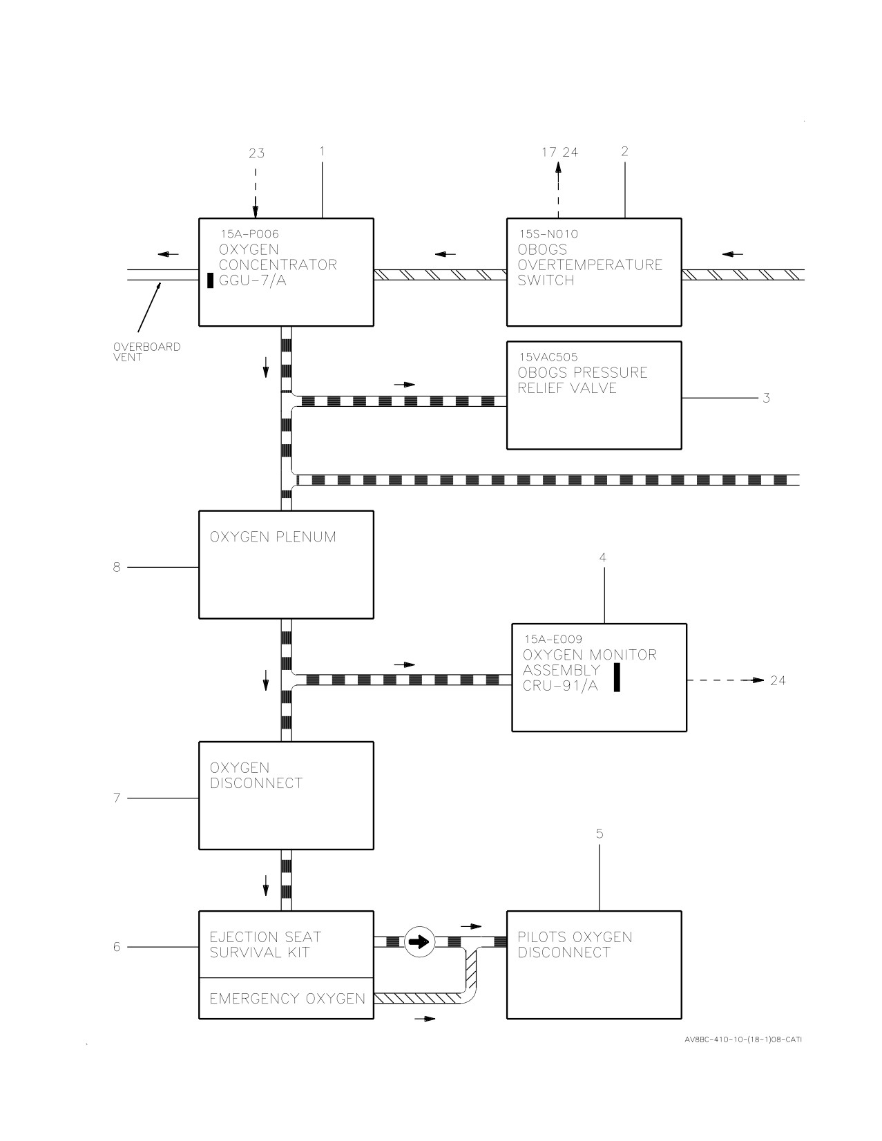
A1-AV8BC-410-100
003 00
Change 2
Page 30
Figure 4. On-Board Oxygen Generating System Flow Diagram (Sheet 1)
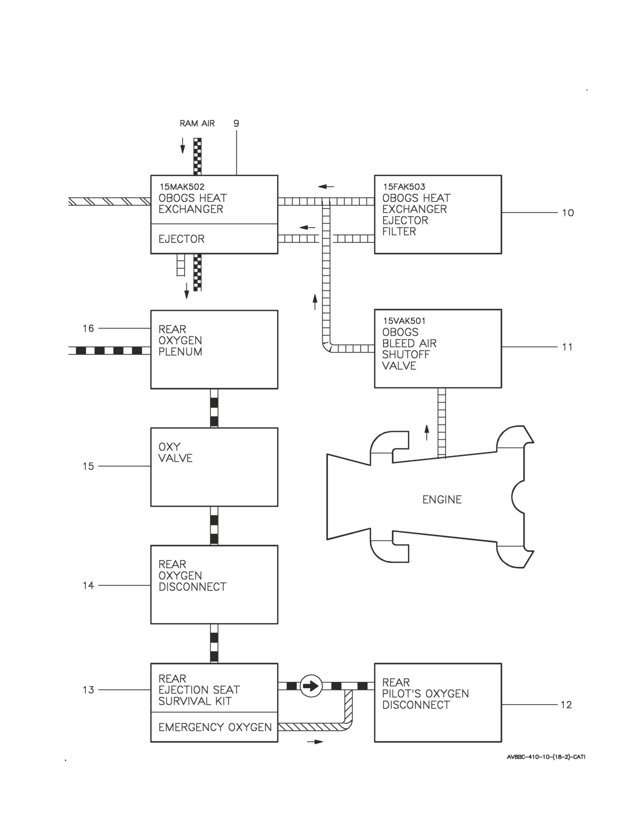
A1-AV8BC-410-100
003 00
Page 31
Figure 4. On-Board Oxygen Generating System Flow Diagram (Sheet 2)
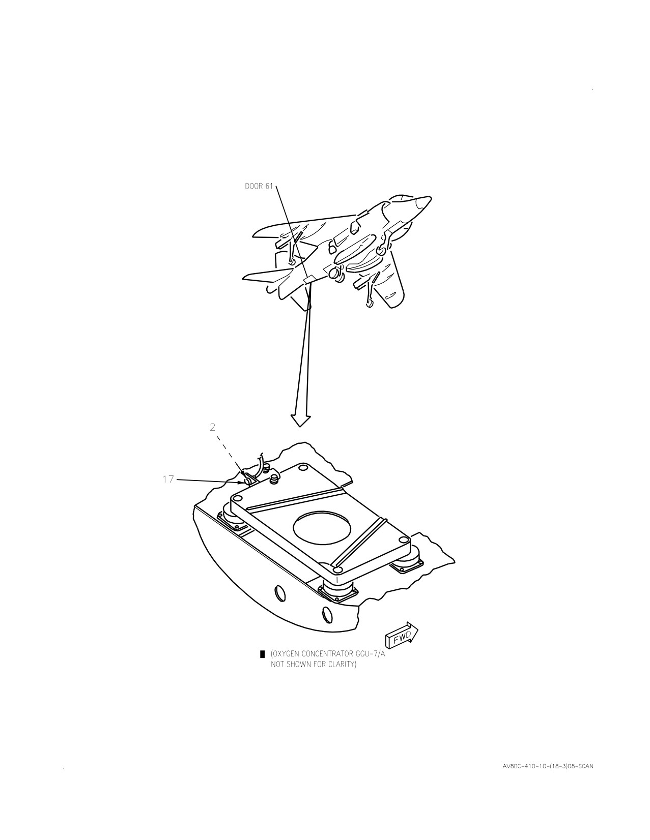
A1-AV8BC-410-100
003 00
Change 2
Page 32
Figure 4. On-Board Oxygen Generating System Flow Diagram (Sheet 3)
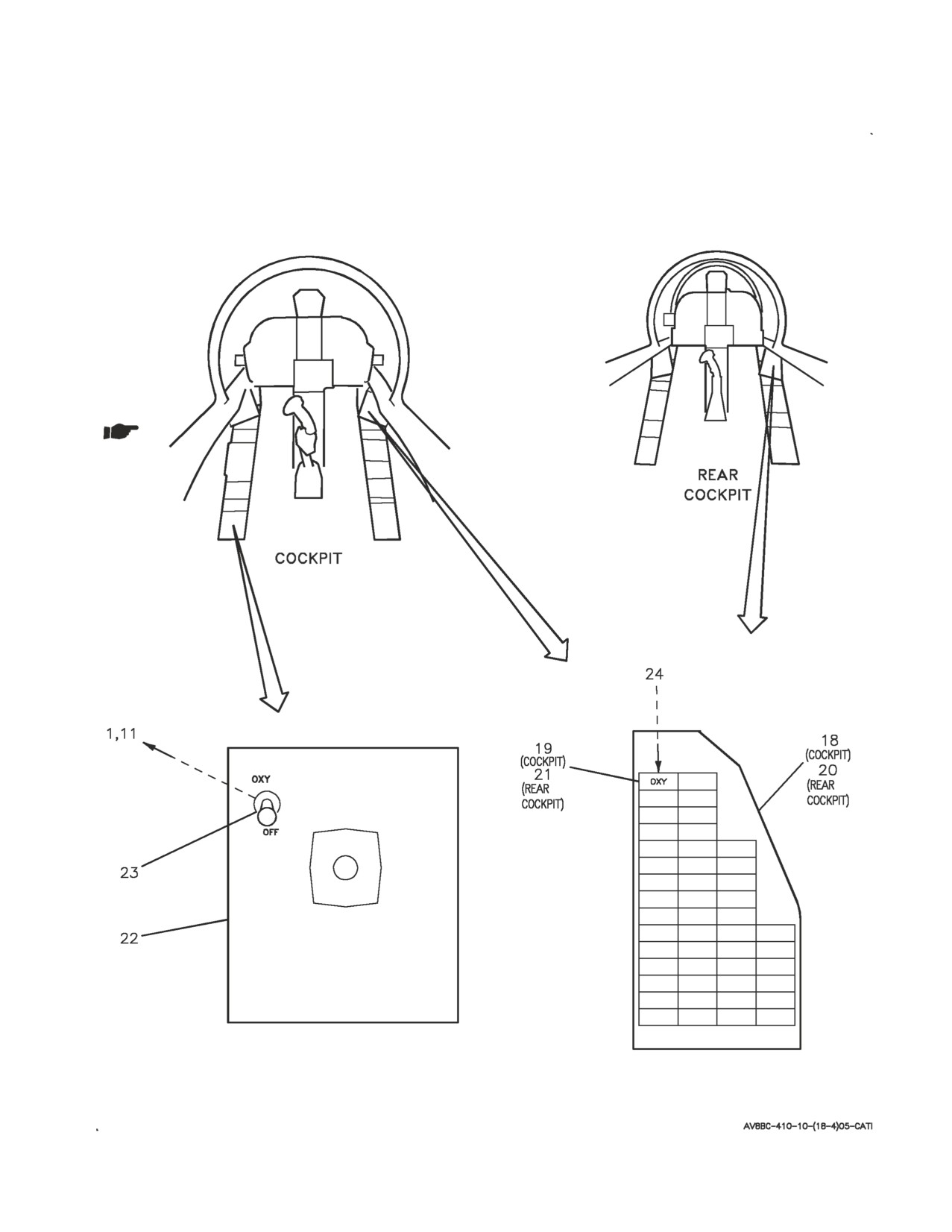
A1-AV8BC-410-100
003 00
Page 33
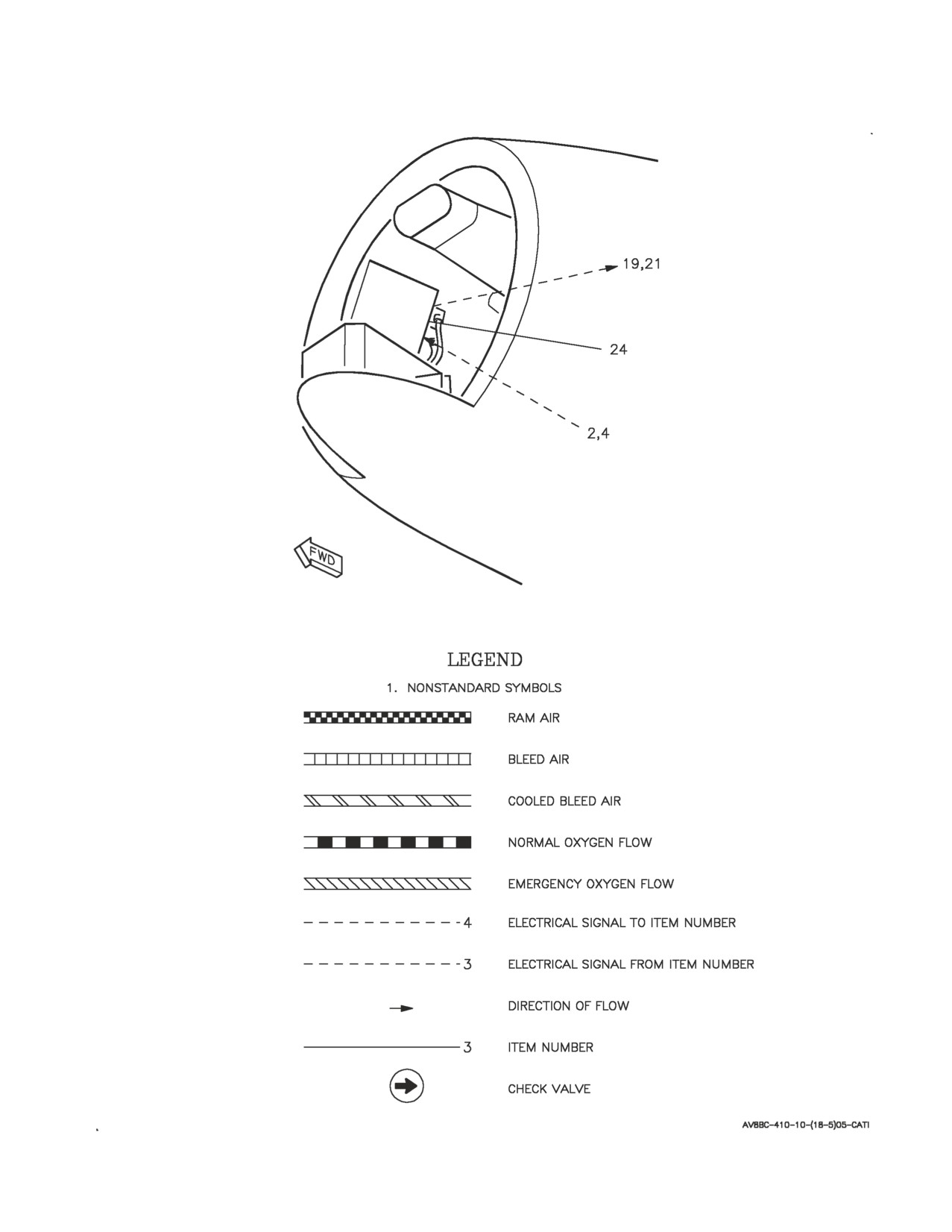
Figure 4. On-Board Oxygen Generating System Flow Diagram (Sheet 4)
A1-AV8BC-410-100
003 00
Page 34
Figure 4. On-Board Oxygen Generating System Flow Diagram (Sheet 5)

A1-AV8BC-410-100
003 00
Change 2
Page
35/(36
blank)
ITEM
NO
NOMENCLATURE
1
OXYGEN CONCENTRATOR GGU-7/A
2
OBOGS OVERTEMPERATURE SWITCH
3
OBOGS PRESSURE RELIEF VALVE
4
OXYGEN MONITOR ASSEMBLY CRU-91/A
5
PILOTS OXYGEN DISCONNECT
6
EJECTION SEAT SURVIVAL KIT
7
OXYGEN DISCONNECT
8
OXYGEN PLENUM
9
OBOGS HEAT EXCHANGER
10
OBOGS HEAT EXCHANGER EJECTOR FILTER
11
OBOGS BLEED AIR SHUTOFF VALVE
12
REAR PILOTS OXYGEN DISCONNECT
13
REAR EJECTION SEAT SURVIVAL KIT
14
REAR OXYGEN DISCONNECT
15
OXY VALVE
16
REAR OXYGEN PLENUM
17
OBOGS O TEMP INDICATOR
18
CAUTION/ADVISORY INDICATOR LIGHT ASSEMBLY
19
OXY CAUTION LIGHT
20
REAR CAUTION/ADVISORY INDICATOR LIGHT ASSEMBLY
21
OXY CAUTION LIGHT
22
PILOT SERVICES PANEL ASSEMBLY
23
OXY SWITCH
24
ANNUNCIATOR LIGHT CONTROLLER
Figure 4. On-Board Oxygen Generating System Flow Diagram
(Sheet 6)
A1-AV8BC-410-100
004 00
Change 7 - 15 May 2004
Page 1
ORGANIZATIONAL MAINTENANCE
PRINCIPLES OF OPERATION
DESCRIPTION AND OPERATION
CABIN COOLING AND DEFOG SYSTEM
Reference Material
Power Plant and Related Systems
A1-AV8BD-290-100
Basic Engine
WP003 00
Environmental Control System
A1-AV8BC-410-100
Cabin Pressurization System
WP006 00
Component Locator - Cabin Cooling And Defog System
WP005 00
Forward Avionics Cooling System
WP008 00
Electrical Systems
A1-AV8BB-420-100
DC Power System
WP004 00
Electrical Systems
A1-AV8BD-420-100
DC Power System
WP004 00
Lighting Systems
A1-AV8BB-440-100
Warning/Caution/Advisory Lighting System
WP007 00
Landing Gear And Related Systems
A1-AV8BB-130-100
Landing Gear System
WP003 00
Alphabetical Index
Subject
Page No.
Cabin Cooling and Defog System Simplified Schematic, Figure 1
11
Description
3
Component Description
3
Cabin ECS Air Filter Assembly
3
Cabin ECS Check Valve
3
Cabin ECS Pressure Regulating and Shutoff Valve
3
Cabin Temperature Sensor
3
Cold Air Unit
3
Defog Shutoff Valve
3
Duct Temperature Sensor
3
ECS Control Panel Assembly
3
ECS Louvers
3
ECS Pressure Switch
4
Forward Vent/Defog Valve
3
Primary Heat Exchanger
4
Rear Vent/Defog Valve
4