F-14D. FLIGHT MANUAL (2004) - page 18
NAVAIR 01-F14AAP-1B
SEE IC # 32
L AND/OR R FUEL
PRESS LIGHT(S)
FUEL
AND 10 SEC
WARNING TONE
1. Both throttles .
MIL Power or Less
2. Restore aircraft to 1.0g flight.
If both lights remain on:
3. Increase positive g’s to greater than 1.0g.
4. Descend to below 25,000 feet.
5. Maintain cruise power settings or less.
6. Land as soon as possible.
D Illumination of both lights and the
warning tone may be indicative of a
total motive flow failure. Zero or
negative-g flight should be avoided.
D Complete loss of motive flow will
result in the sump tank interconnect
and the engine feed crossfeed valve
remaining in the closed position, iso-
lating the forward and aft systems.
Consequently, single-engine opera-
tion will cause fuel on the opposite
side to be unavailable.
CONTINUED
Change 3 w/ IC 33
123
NAVAIR 01-F14AAP-1B
SEE IC # 32
If one light remains on:12
3. No afterburner above 15,000 feet.
4. Fuel distribution .
Monitor
(balance if required)
5. Land as soon as practicable.
If migration occurs after balancing, as indicated by a 100
to 300 PPM increase on the inoperative side or a 100 to
300 PPM decrease on the operative side above expected
burn rate according to indicated fuel flow:
6. FUEL PRESS ADVSY CB − PULL (7F1).
Note
Pulling the FUEL PRESS ADVSY CB
will cause the engine crossfeed valve
to close and the inoperative side fuse-
lage motive flow shutoff valve to open.
This will reduce the amount of fuel
transfer from the operative side to the
inoperative side.
CONTINUED
124
Change 3 w/ IC 33
NAVAIR 01-F14AAP-1B
SEE IC # 32
Note
The L or R FUEL PRESS light and/or
warning tone will extinguish when the
FUEL PRESS ADVSY CB is pulled.
7. Maintain cruise power or less.
8. Fuel distribution − monitor (balance if required).
If the sump tank interconnect valve has
failed, selecting AFT or FWD on the FEED
SWITCH could result in fuel migration to
the inoperative side. If fuel migration
occurs after selecting AFT or FWD on the
FEED SWITCH (as indicated by a 100 to
300 PPM increase on the inoperative
side), immediately return the feed switch
to NORM.
9. Land as soon as possible.
L OR R FUEL LOW LIGHT
1. DUMP switch
OFF
2. Fuel distribution . . Check (balance if required)
(see below if one wing does not transfer)
If wing and/or external fuel remains:
3. WING/EXT TRANS . .
ORIDE
4. Land as soon as practicable.
Change 3 w/ IC 33
124a
NAVAIR 01-F14AAP-1B
SEE IC # 32
FUEL TRANSFER FAILURES
CAUTION
Wing and external fuel will not transfer
with refuel probe switch in ALL EXTD.
If probe extension required, select FUS
EXTD to enable transfer.
Note
Fuel management panel will be inop-
erative if FUEL MGT PLN cb (RC1) is
out.
1. Fuel Management Panel cb . . Check in (RC1)
If wing fuel does not transfer:
2. WING/EXT TRANS switch .
ORIDE
If one wing still does not transfer:
3. FEED switch . .
Select High
Fuselage Tape Side
If wing fuel does not decrease after 2 minutes or wing fuel
transfer is completed:
4. FEED switch
NORM
CONTINUED
124b
Change 3
NAVAIR 01-F14AAP-1B
If external tanks fail to transfer or transfer slowly:
Note
Descending below freezing level may
thaw possible frozen valves.
2. WING/EXT TRANS .
ORIDE
If fuel continues to transfer improperly or does not
transfer:
3. In-flight refueling probe .
All Extend,
Then Retract
4. Apply cyclic positive or negative g’s.
5. AIR SOURCE pushbutton .
OFF Then RAM
Then ON (below 35,000
feet, less than 300 KIAS)
6. If conditions permit, descend below the freezing
level and periodically check for good transfer.
CONTINUED
Change 1
125
NAVAIR 01-F14AAP-1B
CV arrestment, CV touch-and-go, or
normal field landings with full or partial
fuel in the external tanks are not autho-
rized because of overload of the na-
celle backup structure. Only minimum
rate-of-descent landings
(minimum
sink rate) are authorized.
Note
CSDC flycatcher
71-00031 displays
free airstream temperature; if first digit
is an even number, the temperature is
above freezing.
WINGS DO NOT ACCEPT FUEL WITH SWITCH IN
ALL EXTD POSITION
1. REFUEL PROBE .
FUS EXTD
2. WING/EXT TRANS .
OFF
WINGS ACCEPT FUEL WITH SWITCH IN FUS
EXTD POSITION
1. WING/EXT TRANS .
ORIDE
UNCOMMANDED DUMP
1. DUMP switch .
Check OFF
2. FUEL FEED/DUMP (RD1) cb .
Pull
CONTINUED
126
NAVAIR 01-F14AAP-1B
Pulling the fuel feed/dump circuit
breaker (RD1) isolates the right and left
fuel systems. It also deactivates the
function of the feed switch, the auto-
matic balance functions, and the fuel
dump system. Should single engine
operation subsequently be necessary,
useable fuel will be limited to only what
is available on the operating side.
FUEL LEAK
1. Land as soon as possible.
CAUTION
Use of afterburner with fuel leak should
be limited to emergency use only.
2. WING/EXT TRANS .
OFF
If abnormal fuel quantity decrease ceases, fuel leak is in
wing/wing pivot or attachment points for auxiliary tanks:
3. If leak is not stopped, it is in engine/nacelle area.
Proceed immediately with next step.
4. FUEL FEED/DUMP (RD1) cb .
Pull
CONTINUED
Change 3
126a
NAVAIR 01-F14AAP-1B
Pulling the fuel feed/dump circuit
breaker (RD1) isolates the right and left
fuel systems. It also deactivates the
function of the feed switch, the auto-
matic balance functions, and the fuel
dump system. Should single engine
operation subsequently be necessary,
useable fuel will be limited to only what
is available on the operating side.
Note
Enough time should be allowed for
quantity tapes/feeds to develop split
so that leak can be isolated to left or
right feed group. Affected side will be
low side.
5. Throttle (affected side) .
OFF
6. Conditions permitting, allow rpm to decelerate
to windmill rpm.
7. FUEL SHUT OFF .
Pull
8. Refer to Single-Engine Cruise Operations.
126b Change 3
NAVAIR 01-F14AAP-1B
SEE IC # 32
FUEL IMBALANCE/FUEL QUANTITY
BALANCING
AB operation is not recommended with
a fuel imbalance or with indications of
venting fuel.
Note
Fuel quantity balancing is not required
prior to completion of wing/external
tank transfer or until one fuselage tape
drops below 4,500 pounds.
WITH A FUEL STATE BELOW 4500 POUNDS IN EITHER
THE AFT/LEFT OR FWD/RT FEED GROUPS AND A FUEL
SPLIT GREATER THAN 1500 POUNDS BETWEEN THE
AFT/LEFT AND FWD/RIGHT FEED GROUPS:
1. Both throttles − MIL power or less.
2. FEED SWITCH − select high fuselage tape side.
Note
D If practical, obtain a visual inspec-
tion for venting fuel. Do not delay
execution of emergency procedures
for visual inspection.
D Indication of fuel balancing should
appear within 3 minutes of selecting
HYD
the high fuselage tape side.
D With a high quantity in the FWD/RT
fuel system, the greater static head
pressure, particularly in nose−up atti-
tudes can cause overfilling of the
AFT/LT fuel system and subsequent
fuel venting. To prevent this, the feed
switch should be returned to NORM
before the AFT/LT tape reaches 6,200
Change 3 w/ IC 32
127
NAVAIR 01-F14AAP-1B
SEE IC # 32
pounds. Overfilling is indicated by a
quantity of 6,600 pounds or greater in
the FWD/RT system or 6,200 pounds
or greater in the AFT/LT system.
If no venting is observed and/or the fuel imbalance is cor-
rected with the fuel feed switch:
3. FUEL FEED SWITCH − As required and land as
soon as practicable.
If the sump tank interconnect valve has
failed closed, selecting AFT or FWD on
the FUEL FEED SWITCH could result in
rapid increase of the fuel imbalance. If
this occurs (as indicated by an imbalance
increase of 100 to 300 PPM) immediately
return the FEED SWITCH to NORM.
If fuel venting exists and/or fuel imbalance exceeds 2,000
pounds:
4. FUEL FEED SWITCH − NORM.
Venting fuel in conjunction with an
uncontrollable fuel split is indicative of
a motive flow failure and can result in
HYD
the high feed group having trapped/un-
usable fuel. If this occurs, aircrew may
have as little as 4,500 pounds of usable
fuel remaining and a new bingo profile
may be required.
5. Determine useable fuel and land as soon as
possible.
If indications of a fuel leak exist:
6. Refer to FUEL LEAK PROCEDURE (page 126a).
128
Change 3 w/ IC 32
NAVAIR 01-F14AAP-1B
HYDRAULIC
Index
BACKUP FLIGHT MODULE FAILURE .
144
BOTH COMBINED AND FLIGHT
PRESSURE ZERO .
139
COMBINED PRESSURE APPROXIMATELY
2,400 TO 2,600 PSI .
131
COMBINED PRESSURE ZERO .
133
FLIGHT PRESSURE APPROXIMATELY
2,400 TO 2,600 PSI .
136a
FLIGHT PRESSURE ZERO .
138
LOW-BRAKE ACCUMULATOR PRESSURE .
144
Change 1 129/(130 blank)
NAVAIR 01-F14AAP-1B
COMBINED
PRESSURE
HYDRAULIC
APPROXIMATELY
2,400 TO 2,600 PSI
If hammering
(cavitation) is experi-
enced in the hydraulic system,
component rupture is imminent, turn
the hydraulic transfer pump switch
(BIDI) — OFF.
1. HYD ISOL switch .
FLT
Note
Monitor AUX BRAKE PRESSURE
gauge. Tap wheelbrakes to seat priority
valve if pressure is decreasing.
2. In-flight REFUEL PROBE switch .
EXTD
(In carrier environment)
CAUTION
Wing and external fuel will not transfer
with refuel probe switch in ALL EXTD.
If probe extension required, select FUS
EXTD to enable transfer.
3. Wing sweep .
Set at 20_
4. L INLET RAMP switch .
STOW
(less than 1.2 IMN)
CONTINUED
Change 1
131
NAVAIR 01-F14AAP-1B
If WING SWEEP advisory light is illumi-
nated, pulling L AICS (LF2) cb may
cause unintentional wing sweep un-
less WING SWEEP DRIVE NO. 1 (LE1)
and WG SWP DR NO. 2/MANUV FLAP
(LE2) cb’s are pulled.
5. L AICS cb .
Pull (LF2)
Note
Pulling the AICS cb while airborne may
illuminate the FCS CAUTION and ARI
DGR lights. Above about 600 KIAS, the
PITCH SAS and ROLL DGR lights will
also be illuminated. These should clear
with a MASTER RESET following a pro-
grammer reset.
6. L INLET RAMP switch .
AUTO
7. DLC .
Do not engage
8. EMERG FLT HYD switch .
HIGH
(on final, committed to land)
9. Land as soon as possible.
CAUTION
Monitor remaining hydraulic system
pressure since the MASTER CAUTION
and HYD PRESS lights will not illumi-
nate if the remaining system fails.
132
NAVAIR 01-F14AAP-1B
COMBINED PRESSURE ZERO
1. HYD ISOL switch .
FLT
2. HYD TRANSFER PUMP switch .
SHUTOFF
3. In-flight REFUEL PROBE switch .
EXTD
(in carrier environment)
CAUTION
Wing and external fuel will not transfer
with refuel probe switch in ALL EXTD.
If probe extension required, select FUS
EXTD to enable transfer.
4. Wing sweep .
Set at 20_
5. EMERG FLT HYD .
LOW
D If the INLET RAMPS switch is not
placed in STOW prior to the pressure
reaching zero, do not place it in
STOW after complete loss of pres-
sure. Trapped fluid may be the only
thing holding the affected ramp in
position.
CONTINUED
Change 1
133
NAVAIR 01-F14AAP-1B
D
An outboard spoiler module failure
with flaps extended, below
180
KIAS, and with a combined failure
rendering the inboard spoilers inop-
erative, can result in asymmetric
spoiler float such that the aircraft
may not be flyable at normal ap-
proach airspeeds. A small amount of
spoiler float can significantly in-
crease approach speeds.
D
Do not return to AUTO (LOW) mode
once module is selected on (HIGH or
LOW) with operating flight hydraulic
system. When operated in conjunc-
tion with zero combined pressure,
some backup module fluid will be
expelled by thermal expansion. The
module will remain fully serviced
and operate normally as long as
elevated temperatures are maintai-
ned. Once operating, the module
should not be turned off in flight
without combined system pressure
available to reservice it. Doing so
would result in fluid contraction and
an underserviced condition that
could prevent subsequent pump
operation.
134
Change 1
NAVAIR 01-F14AAP-1B
CAUTION
D Loss of combined pressure with
landing flaps down may allow the
auxiliary flaps to cycle causing mod-
erate pitch oscillations.
D Monitor remaining hydraulic system
pressure since the MASTER CAU-
TION and HYD PRESS lights will not
illuminate if the remaining system
fails.
Note
Complete loss of combined hydraulic
pressure will result in the following
caution lights due to the loss of a single
channel SAS actuator function: PITCH
SAS, ROLL DGR, YAW DGR, ARI DGR,
and SPOILERS lights.
The following important equipment is inoperative:
a. One-half authority of SAS/ARI actuators in
pitch, roll and yaw.
b. L AICS.
c. Inboard spoilers.
d. Emergency generator.
e. DLC.
f. Speedbrakes.
g. Normal hook.
CONTINUED
Change 1
135
NAVAIR 01-F14AAP-1B
h. Hook extend (emergency actuation available).
i. Flaps and slats
(emergency actuation
available).
j. Landing gear (emergency actuation available).
k. Wheelbrakes (emergency actuation available).
l. Refuel probe (emergency actuation available
if system fluid remains in return line).
m. Auxiliary flaps.
n. Nosewheel steering.
o. Gun drive.
6. LDG GEAR handle .
EMERG DN
7. HOOK
EMERG DN
8. AUX FLAP/FLAP CONTR cb .
Pull (7G3)
9. Flaps (no auxiliary flaps available) .
DN
10. Brake accumulator (handpump) .
Check
11. ANTI SKID SPOILER BK switch . SPOILER BK
(OFF for CV)
12. EMERG FLT HYD switch .
HIGH
(on final, committed to land)
Do not return to AUTO (LOW) mode
once module is selected on (HIGH or
LOW) with operating flight hydraulic
system.
13. Make arrested landing as soon as possible.
CONTINUED
136
Change 1
NAVAIR 01-F14AAP-1B
After landing:
14. Do not taxi out of arresting gear.
15. Engines .
OFF
FLIGHT PRESSURE APPROXIMATELY 2,400
TO 2,600 PSI
If hammering
(cavitation) is experi-
enced in the hydraulic system, compo-
nent rupture is imminent. Turn the
hydraulic transfer pump switch (BIDI)
OFF.
1. Wing sweep .
Set at 20_
2. R INLET RAMP switch .
STOW
(less than 1.2 IMN)
3. R AICS cb .
Pull (LG2)
CONTINUED
Change 1
136a/(136b blank)
NAVAIR 01-F14AAP-1B
Note
Pulling the AICS cb while airborne may
illuminate the FCS CAUTION and ARI
DGR lights. Above about 600 KIAS, the
PITCH SAS and ROLL DGR lights will
also be illuminated. These should clear
with a MASTER RESET following a pro-
grammer reset.
4. R INLET RAMP switch .
AUTO
5. EMERG FLT HYD switch .
HIGH
(on final, committed to land)
CAUTION
Monitor remaining hydraulic system
pressure since the MASTER CAUTION
and HYD PRESS lights will not illumi-
nate if the remaining system fails.
The following important equipment is inoperative:
a. Normal hook .
Restored by
weight-on-wheels;
hook handle restowed
Note
Arrested landing will require emergency
hook extension.
6. Land as soon as possible.
137
NAVAIR 01-F14AAP-1B
FLIGHT PRESSURE ZERO
1. HYD TRANSFER PUMP switch .
SHUTOFF
2. Wing sweep .
Set at 20_
3. EMERG FLT HYD switch .
LOW
If the INLET RAMPS switch was not
placed in STOW prior to pressure
reaching zero, do not place it in stow af-
ter complete loss of pressure. Trapped
fluid may be the only thing holding the
affected ramp in position.
CAUTION
Monitor remaining hydraulic system
pressure since the MASTER CAUTION
and HYD PRESS lights will not illumi-
nate if the remaining system fails.
Note
Complete loss of flight hydraulic pres-
sure will result in the following caution
lights due to the loss of single channel
SAS actuator function: PITCH SAS,
ROLL DGR, YAW DGR, and ARI DGR
lights.
CONTINUED
138
NAVAIR 01-F14AAP-1B
The following important equipment is inoperative:
a. One-half authority of SAS/ARI actuators in
pitch, roll and yaw.
b. ACLS.
c. R AICS.
d. Normal hook .
Restored by
weight-on wheels;
hook handle restowed
4. EMERG FLT HYD switch .
HIGH
(on final, committed to land)
5. Land as soon as possible.
Note
Arrested landing will require emergency
hook extension.
BOTH COMBINED AND FLIGHT PRESSURE
ZERO
1. EMERG FLT HYD switch .
LOW
2. Do not attempt CV recovery. Divert if possible.
If any undesirable motions or oscilla-
tions occur, immediately release the
stick and permit the motions to damp-
en before resuming active control.
CONTINUED
139
NAVAIR 01-F14AAP-1B
D Do not attempt IMC or close night
formation while in the LOW mode.
D Operations of more than 8 minutes
total in HIGH mode may fail the
BFCM motor. The LOW mode should
be selected as soon as practicable
following a waveoff or bolter, and the
HIGH mode reselected on the subse-
quent approach.
D Inboard spoilers can be expected to
float, causing uncomfortable lateral
stick requirements for level flight.
Do not trim out lateral forces.
3. Reduce airspeed to below 250 KIAS if practicable.
Note
Airspeeds less than 250 KIAS while in
the LOW mode will reduce the suscep-
tibility of exceeding maximum stabiliz-
er deflection rates.
The following important equipment is operative in flight:
a. Horizontal stabilizers (significantly reduced
rate, no SAS/ARI).
b. Rudders (slightly reduced rate, no SAS/ARI).
c. Main flaps and slats (reduced rate via thumb-
wheel or flap handle).
d. Outboard spoilers.
CONTINUED
140
NAVAIR 01-F14AAP-1B
e. Hydraulic handpump.
f. Landing gear
(emergency actuation
available).
g. Hook extend (emergency actuation available).
h. Refuel probe (emergency actuation available
if system fluid remains in return line).
i. Wheelbrakes (emergency actuation available).
If in-flight refueling is required:
4. Decelerate with tanker to 180 KIAS.
5. Maneuver flaps .
Extend
6. EMERG FLT HYD switch .
HIGH
prior to moving to pre-contact)
7. Avoid abrupt control inputs during contact.
D Any abrupt control input to effect
engagement can rate limit the stabil-
izers and result in loss of control.
The pilot must resist spotting the
basket and rely on RIO commentary
to perform engagement.
D Extended LOW mode operation (>30
minutes) after in-flight refueling will
permit several additional minutes in
HIGH mode for subsequent landing.
D Tanking from large-body tankers
(KC-130, KC-10, KC-135) is hazard-
ous and should not be attempted.
CONTINUED
141
NAVAIR 01-F14AAP-1B
Note
Once engaged, the airspeed can safely
be increased to 200 KIAS to improve
the transfer rate.
8. EMERG FLT HYD switch .
LOW
(immediately once clear of tanker)
9. Maneuver flaps .
Retract
Field recovery:
10. LDG GEAR handle .
EMERG DN
11. Maneuver flaps .
Extend with thumbwheel
12. Maneuver flap cb .
Pull (LE2)
13. HOOK handle .
EMERG DN
14. Brake accumulator .
Check
Established on final, committed to land:
15. EMERG FLT HYD switch .
HIGH
D Aggressive nose movement in close
can rate limit the stabilizers, result-
ing in low altitude loss of control. Do
not use APCS.
D Inboard spoilers can be expected to
float, causing uncomfortable lateral
stick requirements for level flight.
Do not trim out lateral forces.
CONTINUED
142
NAVAIR 01-F14AAP-1B
CAUTION
D Waveoff performance from low pow-
er settings is very poor. Carrying ex-
tra speed during IMC approach will
improve waveoff performance by
permitting smooth rotation to
15
units AOA to break the rate of
descent while the engines are
accelerating.
D Prolonged operation of the BFCM in
the HIGH mode may cause failure of
the module. The LOW mode should
be selected as soon as practicable
following a waveoff or bolter and the
HIGH mode reselected on the subse-
quent approach.
16. If wings are at 20_ .
Fly straight-in
approach between
15 units AOA and 180 KIAS
17. If wings are > 20_ .
Fly straight-In
approach at
15 units AOA
Note
Control in LOW mode is satisfactory
for performing transition to dirty confi-
guration. Pitching moment caused by
flap transition is easily countered with
electrical trim because of very slow ex-
tension rate.
18. Make arrested landing as soon as possible.
CONTINUED
143
NAVAIR 01-F14AAP-1B
After landing:
19. Do not taxi out of arresting gear.
20. Throttles .
OFF
BACKUP FLIGHT MODULE FAILURE
CAUTION
Prolonged use of backup flight control
module in the high mode may result in
failure of the module.
1. FLT HYD BACKUP PH A, B, C,
(2A1, 2C1, 2E1) cb’s .
In
2. Land as soon as possible.
LOW-BRAKE ACCUMULATOR PRESSURE
IN FLIGHT
1. HYD ISOL .
T.O./LDG
If pressure does not recover:
2. LDG GEAR handle .
DN
3. HYD HANDPUMP .
Recharge Accumulator
Note
Monitor AUX BRAKE PRESSURE
gauge. Tap wheelbrakes to seat priority
valve if pressure is decreasing.
CONTINUED
144
NAVAIR 01-F14AAP-1B
If accumulator cannot be recharged:
4. Make arrested landing as soon as practicable.
5. Parking brake .
Pull (to lock wheels).
LAND/
LAND
GEAR
145
NAVAIR 01-F14AAP-1B
LAND/
LAND
GEAR
146
NAVAIR 01-F14AAP-1B
LANDING GEAR/LANDING
Index
AFT WING SWEEP LANDING .
163
ARRESTING HOOK EMERGENCY DOWN .
156
AUXILIARY FLAP FAILURE .
160
BARRICADE ARRESTMENT .
157
BLOWN TIRE LANDING .
160
BRAKE FAILURE AT TAXI SPEED .
158
GROUND ROLL BRAKING FAILURE .
157
LANDING GEAR EMERGENCY LOWERING .
155
LANDING GEAR INDICATES SAFE GEAR
DOWN, TRANSITION LIGHT ILLUMINATED .
154
LANDING GEAR INDICATES UNSAFE GEAR
DOWN, TRANSITION LIGHT ILLUMINATED .
151
LANDING GEAR INDICATES UNSAFE
GEAR DOWN, TRANSITION LIGHT OUT .
151
LANDING GEAR INDICATES UNSAFE GEAR
UP OR TRANSITION LIGHT ILLUMINATED .
149
LANDING GEAR MALFUNCTION .
149
LANDING WITH AFT HUNG ORDNANCE .
165
LAUNCH BAR LIGHT .
155
NO FLAPS AND NO SLATS LANDING .
161
147/(148 blank)
NAVAIR 01-F14AAP-1B
LANDING GEAR
LANDING GEAR/
MALFUNCTION
LANDING
1. Remain below 280 KIAS.
2. Combined hydraulic pressure .
Check
3. If less than 3,000 psi, refer to combined hydrau-
lic failure procedures.
LANDING GEAR INDICATES UNSAFE GEAR
UP OR TRANSITION LIGHT ILLUMINATED
1. LDG GEAR handle .
DN
If safe gear down indication is obtained and transition light
is out:
2. Landing gear .
Leave Down
3. Obtain visual check of gear condition.
CONTINUED
149
NAVAIR 01-F14AAP-1B
A hyperextended main strut, whether
caused by a broken piston or overex-
tended piston barrel and/or main strut
with a cocked wheel, will likely result in
a combined hydraulic system failure
while airborne, and a sheared strut
upon touchdown. A hyperextended
main strut is evident to a wingman by
full vertical extension of the scissors
and broken brake lines and to the tower
or LSO by one main gear hanging no-
ticeably lower than the other. When ei-
ther of these situations occurs, landing
procedures for a stub (MLG) mount
must be followed.
4. Land as soon as practicable.
CAUTION
If landing gear indicates unsafe after
retraction and a down-and-locked indi-
cation can be obtained, the brake ped-
als should be depressed for 60 sec-
onds to ascertain whether brake
hydraulic lines have been severed. If
brake hydraulic lines are severed and a
combined hydraulic failure occurs,
refer to combined hydraulic system
failure procedures.
150
Change 2
NAVAIR 01-F14AAP-1B
LANDING GEAR INDICATES UNSAFE GEAR
DOWN, TRANSITION LIGHT OUT
1. Transition light bulb .
Check
(LTS TEST)
CAUTION
If associated with launch bar light,
leave gear down and obtain visual
check.
2. Landing gear .
Cycle
If condition still exists:
3. Obtain visual check if possible.
4. Make normal landing.
LANDING GEAR INDICATES UNSAFE GEAR
DOWN, TRANSITION LIGHT ILLUMINATED
1. Obtain visual check if possible.
CAUTION
Visual determination of nose landing
gear unlocked status is assisted by a
red band painted on the nose landing
gear drag brace oleo. If red is visible,
the nosegear is not locked.
151
NAVAIR 01-F14AAP-1B
CAUTION
During an airborne visual inspection of
the main landing gear (even if the paint
stripe across the drag brace knee pin
appears to be straight), the possibility
exists that the downlock actuator has
failed and the gear may not be locked
in the down position.
2. LDG GEAR handle .
Cycle
If still unsafe:
3. Increase airspeed to 280 KIAS, pull positive g’s,
and yaw aircraft.
If main landing gear is still unsafe, go to step 5:
If nose landing gear indicates unsafe, transition light illu-
minated, continue with step 4:
4. LDG GEAR handle .
Cycle UP Then DN
in Less Than 2 Seconds
CONTINUED
152
NAVAIR 01-F14AAP-1B
Failure to place the LDG GEAR handle
to DN immediately after selecting UP
may allow the main landing gear doors
to receive the signal to close with the
main gear struts extended, causing
damage to the doors and inducing a
possible combined hydraulic or brake
system failure. Do not reselect UP with
the LDG GEAR handle after the doors
attempt to close, as indicated by an un-
safe main-mount or visual inspection.
Note
Use of the above procedure should be
done at the intended point of landing or
within range of an acceptable divert
field exercising a gear down bingo
profile.
5. LDG GEAR handle .
EMERG DN
(refer to Landing Gear
Emergency Lowering)
Note
Use of the Landing Gear Emergency
Lowering procedure will result in loss
of nosewheel steering.
If still unsafe and visually confirmed unsafe or gear posi-
tion cannot be confirmed:
6. Refer to Landing Gear Malfunctions Emergency
Landing Guide.
CONTINUED
153
NAVAIR 01-F14AAP-1B
CAUTION
D
When landing with a nosegear un-
safe down indication, anticipate
possible nose landing gear col-
lapse. This possibility shall be
reduced by using the brake pedals
to prevent rollback as the arresting
gear reaches full extension and by
setting the parking brake after the
aircraft has stopped.
D
Do not attempt to tow aircraft by the
nosegear until the gear is secured in
the down position.
D
Nose landing gear ground safety pin
installation will not prevent nose-
gear collapse. The nose landing
gear strut must be restrained
against forward rotation.
LANDING GEAR INDICATES SAFE GEAR
DOWN, TRANSITION LIGHT ILLUMINATED
CAUTION
If associated with launch bar light,
leave gear down and obtain visual
check.
1. LDG GEAR handle .
Cycle
If transition light remains on:
2. Obtain visual check.
CONTINUED
154
Change 2
NAVAIR 01-F14AAP-1B
3. Gear/sidebraces appear
in place .
Normal Landing
If sidebraces are confirmed not in place:
4. Refer to Landing Gear Malfunction Emergency
Landing Guide.
LAUNCH BAR LIGHT
1. Landing gear .
Leave Down
2. Obtain visual inspection.
If nosegear is cocked, refer to Landing Gear Malfunction
Guide.
If launch bar is down or visual inspection is not available:
3. Remove arresting cables for field landing.
4. Remove crossdeck pendant Nos. 1 and 4 for CV
landing.
LANDING GEAR EMERGENCY LOWERING
1. Airspeed .
Less Than 280 KIAS
2. LDG GEAR handle .
DN
CAUTION
The LDG GEAR handle should be
pulled with a rapid and continuous
55-pound force until the handle is
loose (fore and aft) in its housing as an
indication of complete extension of the
handle.
CONTINUED
Change 3
155
NAVAIR 01-F14AAP-1B
3. Push LDG GEAR handle in hard, turn
90°
clockwise, pull, and hold.
4. Gear position indication .
Check
(12 seconds)
5. Make arrested landing if available.
If any gear does not come down:
6. Increase speed. Do not exceed 280 KIAS.
7. Apply positive and negative g to force gear
down.
8. Obtain visual in-flight check if possible.
9. Refer to Landing Gear Malfunction Emergency
Landing Guide on page 167.
ARRESTING HOOK EMERGENCY DOWN
1. HOOK handle .
DN
2. HOOK handle .
Pull, Then Rotate
Note
Pull handle aft approximately 4 Inches
and turn counterclockwise. This will
mechanically release the uplatch
mechanism and allow the hook to
extend.
3. Hook transition light .
Check Off
If light is illuminated and hook is visually checked up:
4. HOOK handle .
Restow in DN Position
5. HYD VALVE
CONTR (7E5) cb .
Pull and Reset
After 5 Seconds
CONTINUED
156 Change 1
NAVAIR 01-F14AAP-1B
If light is illuminated and hook is visually checked
down:123
4. RAIN RPL/ANTI-ICE CONTR/
HK CONTR (7C2) cb .
Pull
GROUND ROLL BRAKING FAILURE
*1. ANTI SKID SPOILER BK switch .
Check
*2. MASTER RESET pushbutton .
Depress
Note
Ground roll braking may fail to extend
spoilers on touchdown due to a
momentary miscompare of the weight-
on-wheels switches.
BARRICADE ARRESTMENT
1. External stores .
Jettison (except AIM-7 and
AIM-54 on fuselage stations
if wing is at full forward sweep)
2. External tanks .
Jettison (empty tanks
retained only for
landing gear malfunction)
3. Fuel .
Dump or Burn
(reduce to 2,000 pounds)
4. Hook .
DN (lower to permit
engagement of crossdeck
pendant, which will minimize
barricade engagement
speed and damage to aircraft)
CONTINUED
Change 1
157
NAVAIR 01-F14AAP-1B
5. Fly normal pattern and approach, on-speed,
angle of attack, centerline, and meatball.
Note
Anticipate loss of meatball for a short
period of time during the approach.
Barricade stanchions may obscure the
meatball.
Upon engaging the barricade:
6. Throttles .
OFF
7. Evacuate aircraft as soon as practicable.
Weight limits are:
Wings at 20_ .
51,800 Lb
(max)
Wings > 20_≤ 35_ .
46,000 Lb
(max)
Wings > 35_ .
Not Permitted
BRAKE FAILURE AT TAXI SPEED
*1. ANTI SKID SPOILER BK .
SPOILER BK
or OFF
2. Nosewheel steering .
Engaged
3. Parking brake .
Pull (if required)
parking brake will lock
both main wheels)
CONTINUED
158
NAVAIR 01-F14AAP-1B
Complete loss of hydraulic fluid
through the wheelbrake hydraulic lines
will render the parking brake and nose-
wheel steering ineffective.
If brakes still inoperative:
4. HOOK .
DN
CAUTION
After lowering hook, nosewheel steer-
ing will be automatically centered and
will remain centered until nosewheel
steering is cycled.
5. External lights .
ON
6. Notify ground or tower.
7. Both throttles .
OFF (if required)
(if collision is imminent,
DO NOT delay step 7)
During shipboard operations, aircrew
should not delay ejection decision if
departure from the flight deck is
imminent.
159
NAVAIR 01-F14AAP-1B
BLOWN TIRE LANDING
CAUTION
Do not allow aircraft to roll backward
after the arrestment. The downlock ac-
tuator may have been damaged by tire
failure and rearward movement of the
aircraft could cause the gear to
collapse.
1. Obtain in-flight visual check if possible.
2. ANTI SKID SPOILER BK .
SPOILER BK
(OFF for CV)
3. HOOK .
DN
4. Make carrier or short-field, fly-in arrested land-
ing as soon as practicable.
5. HYD ISOL switch .
T.O./LND (on final)
If arresting gear is not available:
6. Land on centerline.
7. Nosewheel steering .
Engaged
AUXILIARY FLAP FAILURE
1. Wing sweep .
Ensure at 20°
2. AUX FLAP/FLAP CONTR cb (7G3) .
Pull
3. Approach .
15 Units AOA
Note
With AUX FLAP/FLAP CONTR cb
pulled, wings will not sweep aft.
160
NAVAIR 01-F14AAP-1B
NO FLAPS AND NO SLATS LANDING
1. Gross weight. Reduce (weight consistent with
existing runway length and conditions)
2. Flaps .
UP
Setting the FLAP handle to the DN
position inflight may create or aggra-
vate a flap asymmetry condition and
could make the aircraft uncontrollable.
Note
If outboard spoilers are needed for
ground-roll braking, FLAP handle must
be lowered at least
5º on landing
rollout.
3. Fly landing pattern slightly wider than normal or
make straight-in approach at 15 units AOA.
4. Use normal braking technique.
CAUTION
D Maximum airspeed for wheelbrake
application is 165 KIAS at a gross
weight of 46,000 pounds and 145
KIAS at 51,000 pounds.
D Use of full aft stick during landing in
this configuration can result in tail-
pipe ground contact.
CONTINUED
Change 2
161
NAVAIR 01-F14AAP-1B
CAUTION
D Avoid slow approaches. Wing drop
and increased sink rate may occur at
16.5 to 17.5 units AOA.
D Aircrew should expect hot brakes
following high-speed landings. Ap-
plication of the parking brake could
cause the brake assembly to fail and
result in a brake failure.
162
Change 2
NAVAIR 01-F14AAP-1B
DATE: 1 MAY 1980
FUEL GRAD: JP-5
(JP-8, JP-4)
DATA BASIS: FLIGHT
FUEL DENSITY: 6.8
TEST
(6.7, 6.5 lb/gal)
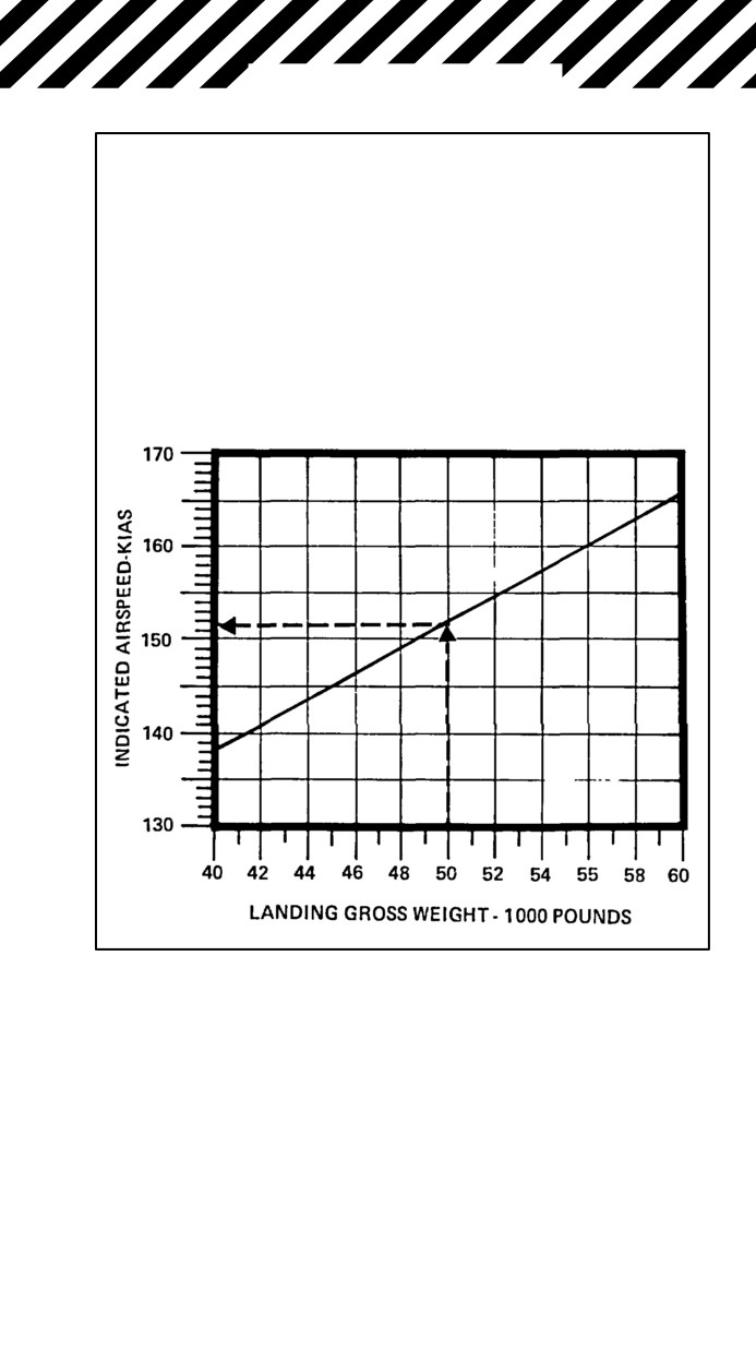
ALL DRAG INDEXES, 0_ FLAP, GEAR DOWN
LANDING APPROACH AIRSPEED (15 UNITS)
Change 2
162a/(162b blank)
NAVAIR 01-F14AAP-1B
AFT WING SWEEP LANDING
Note
CV arrestments are permitted with up
to 40_ wing sweep; emergency barri-
cade engagements are permitted with
up to 35_ wing sweep.
1. Emergency WING SWEEP
handle .
Match Captain Bars
With Actual Wing-Sweep
Position Tape
CAUTION
Closely monitor wingsweep move-
ment when attempting to match handle
with wingsweep position. If abnormal
movement is noticed, immediately
return handle to previous position.
2. Gross weight .
Reduce as Required
If wings equal or less than 50º:
3. Main flaps
Full Down
Note
Main flap/slat extension with the wings
aft of 20° will result in a large nose-
down pitch transient.
If main flaps fail to extend:
4. Maneuvering flaps .
Extend
CONTINUED
163
NAVAIR 01-F14AAP-1B
If maneuvering flaps are used, ensure
that maneuver flap thumbwheel is not
actuated during the approach.
5. DLC and APC .
Do Not Engage
6. Slow-fly aircraft at a safe altitude to determine
approach airspeed (up to 17 units AOA for field
landings with wings aft of 50°) and to evaluate
handling/stall characteristics and waveoff
performance.
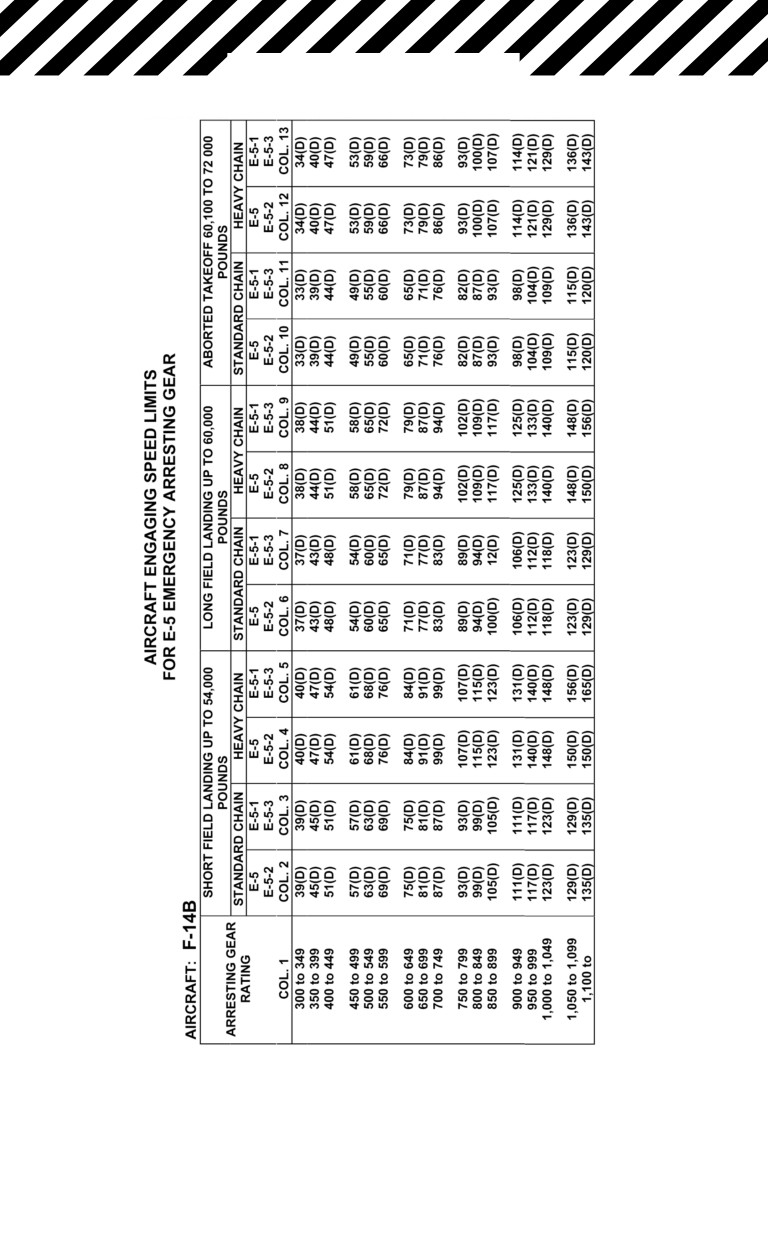
Refer to emergency field arrestment
guide for maximum engagement speed
if field arrestment is desired.
D Refer to landing approach speed
table on page
255 for approach
speed.
7. Fly straight-in approach at 15 units AOA (up to
17 units for field landings with wings aft of 50_).
CAUTION
Ventral fin clearance is reduced at ele-
vated approach AOA. Ensure that a
maximum of 17 units is maintained at
touchdown.
CONTINUED
164
NAVAIR 01-F14AAP-1B
Note
Maximum airspeed for wheelbrake ap-
plication is 165 KIAS at gross weight of
46,000 pounds and 145 KIAS at 51,000
pounds.
LANDING WITH AFT HUNG ORDNANCE
1. Determine location of hung stores. Obtain
visual check if possible.
If hung ordnance exceeds 1000 pounds:
2. Wing sweep .
Set at 25_ if ≤ 2,000 Pounds
Hung Aft;
Set at 30_ if > 2,000 Pounds
Hung Aft
3. Perform transition to gear-down configuration
in straight-and-level flight.
4. AUX FLAP/FLAP/CONTR cb (7G3) .
Pull
5. FLAPS
Full DN
6. Fly straight-in approach at 15 units AOA. Do not
engage APC or DLC.
CV approach:
7. Perform CV arrestment in accordance with ap-
plicable recovery bulletin.
Field approach:
8. Spoiler brake
OFF
9. Perform field arrestment.
CONTINUED
165
NAVAIR 01-F14AAP-1B
Note
Refer to Emergency Field Arrestment
Guide for maximum engagement
speed (page 169).
If arresting gear is not available:
10. If field arrestment is not available,
spoiler brake
BOTH
Expect a significant nose pitchup dur-
ing landing rollout as spoilers deploy.
Full forward stick may be required to
avoid a tail strike.
CONTINUED
166
Change 2

NAVAIR 01-F14AAP-1B
FIELD LANDING
FINAL
ARRESTING
NO ARRESTING
CONFIGURATION
CARRIER LANDINGS
GEAR AVAILABLE
GEAR AVAILABLE
NOTES
NOTES
NOTES
COCKED NOSE
LAND
1, 8, 11
ARRESTED
6, 8, 9,
LAND
6, 9, 11,
GEAR
LANDING
11, 12,
13
13
SIDE-BRACE NOT
LAND
1, 2, 8,
NO
3, 6, 7,
LAND
3, 6, 7,
IN PLACE
11
ARRESTED
8, 11
8, 11
LANDING
NOSE GEAR UP/
LAND
1, 2, 4,
NO
4, 6, 8,
LAND
6, 8, 9,
UNSAFE DOWN
8, 11
ARRESTED
9, 10,
10, 11
LANDING
11
STUB NOSE
LAND
1, 2, 4,
NO
4, 6, 8,
LAND
6, 8, 9,
GEAR
8, 11
ARRESTED
9, 10,
10, 11
LANDING
11
NOSE GEAR UP,
EJECT
1, 2, 4,
PILOT
6, 8,
EJECT
ONE MAIN UP
PILOT
8, 11
OPTION
10, 11,
OPTION
EJECT OR
12
TO LAND
ARREST
IF TANKS
INSTALLE
D
ONE MAIN UP
LAND
1, 2, 8,
ARRESTED
6, 8,
PILOT
5, 6, 8,
UNSAFE
11
LANDING
10, 11,
OPTION
10, 11,
12, 13
EJECT OR
13
LAND
BOTH MAIN UP
EJECT
1, 2, 8,
PILOT
6, 8,
PILOT
6, 8, 10,
UNSAFE
PILOT
11
OPTION
10, 11,
OPTION
11
OPTION
EJECT OR
12
EJECT OR
TO LAND
ARREST
LAND
IF TANKS
INSTALLE-
D
MAINS ONE OR
LAND
1, 2, 4,
NO AR-
4, 5, 6,
LAND
5, 6, 8,
BOTH STUB/
8, 11
RESTED
8, 11
11
MOUNT/HYPER-
LANDING
EXTENDED/
WHEEL COCKED
ALL GEAR UP
EJECT
1, 2, 8,
PILOT
4, 6, 8,
PILOT
6, 8, 10,
PILOT
11
OPTION
10, 11
OPTION
11
OPTION
EJECT OR
EJECT OR
TO LAND
LAND
LAND
IF TANKS
INSTALLE-
D
1. DIVERT IF POSSIBLE
2. HOOK DOWN BARRICADE ENGAGEMENT
3. MINIMIZE SKID AND DRIFT ROLLOUT
4. REMOVE ALL ARRESTING GEAR
5. LAND OFF CENTER TO GEAR DOWN SIDE
6. MINIMUM RATE OF DESCENT LANDING (480 FPM MAX)
7. GRADUAL SYMMETRICAL BRAKING
8. RETAIN EMPTY DROP TANKS
9. LOWER NOSE GENTLY PRIOR TO FALL THROUGH
10. SECURE ENGINES AT AIRFRAME CONTACT
11. EXTERNAL ORDNANCE — SEL JETT IF REQUIRED. ACTIVATE EMERG LANDING
GEAR LOWERING TO ENABLE RAISING GEAR HANDLE FOR SEL OR ACM JETT
12. HOLD DAMAGED GEAR OFF DECK UNTIL PENDANT ENGAGEMENT.
13. ENGAGE NWS IF OPERABLE, USE AS REQUIRED.
LANDING GEAR MALFUNCTION
EMERGENCY LANDING GUIDE
167

NAVAIR 01-F14AAP-1B
MAXIMUM ENGAGING SPEED (KNOTS) (D)
GROSS WEIGHT X 1,000 POUNDS
LONG
MAXIMUM
TYPE OF
FIELD
OFF-CENTER
ARRESTING
LANDING
ENGAGEMENT
GEAR
SHORT-FIELD LANDING (K) (L)
(M)
ABORTED TAKEOFF (A)
(FT)
40
44
48
51.8
54
57
60
64
68
69.8
72
E-28
176
180
179
178
177
176
175
174
172
172
171
40
(B)
E-28 (G)
176
176
160
160
160
160
156
145
145
145
145
40
(B)
M-21
130
130
130
130
125
125
120
115
115
115
113
10
BAK-9
160
160
160
155
150
144
138
131
124
122
118
30
BAK-12 (H)
160
160
159
146
137
118
(J)
(J)
(J)
(J)
(J)
50
DUAL
160
160
160
160
160
160
160
160
160
160
160
30
BAK-12 (C)
BAK-13
160
160
160
160
160
160
160
160
160
160
160
40
(A)
Data provided in aborted takeoff column may be used for emergency high gross weight arrest-
ment.
(B)
Maximum engaging speed limited by aircraft limit horizontal-drag load factor (mass item limit
“G”).
(C)
Dual BAS-12 limits are based on 150 to 300 foot span, 1-1/4 inch cross deck pendant, 50,000
pound weight setting, and 1,200 foot runout. No information available regarding applicability
to other configurations.
(D)
Maximum engaging speed limited by arresting gear capacity, except as noted.
(E)
Off-center engagement may not exceed 25 percent of the runway span.
(F)
Before making an arrestment, the pilot must check with the air station to confirm the maximum
engaging speed because of a possible installation with less than minimum required rated
chain length.
(G)
Only for the E-28 systems at Keflavik and Bermuda with 920 foot tapes.
(H)
Standard BAK-12 limits are based on 150 foot span, 1 inch cross deck pendant, 40,000 pound
weight setting, and 950 foot runout. No information available regarding applicability to other
configurations.
(J)
Engaging speed limit is 96 knots at 59,000 pounds. Due to runout limitations it is recom-
mended this gear not be engaged at weights greater than 59,000 pounds.
(K)
Maximum of 3.0_ glideslope.
(L)
Consult appropriate section for recommended approach speed.
(M)
Flared or minimum rate of descent landing.
EMERGENCY FIELD ARRESTMENT GUIDE
(SHEET 1 OF 2)
CONTINUED
168
NAVAIR 01-F14AAP-1B
SE
EMERGENCY FIELD ARRESTMENT GUIDE
(SHEET 2)
169
NAVAIR 01-F14AAP-1B
SE
170
NAVAIR 01-F14AAP-1B
SINGLE-ENGINE OPERATIONS
Index
SINGLE-ENGINE CRUISE OPERATIONS .
181
SINGLE-ENGINE FAILURE FIELD/CATAPULT
LAUNCH/WAVEOFF .
173
SINGLE-ENGINE LANDING — PRI MODE .
173
SINGLE-ENGINE LANDING — SEC MODE .
176
171/(172 blank)
NAVAIR 01-F14AAP-1B
SINGLE-ENGINE
FAILURE FIELD/
SINGLE-ENGINE
CATAPULT LAUNCH/
OPERATIONS
WAVEOFF
*1. Set 10_ pitch attitude on the waterline (14 units
AOA maximum).
*2. Rudder .
Opposite Roll/Yaw,
Supplemented by Lateral Stick
*3. Both throttles .
As Required for
Positive Rate of Climb
*4. Landing gear .
UP
*5. Jettison .
If Required
If banner tow:
6. Hook .
DN
7. If unable to control aircraft .
Eject
8. Establish 10-unit AOA climb.
9. Climb to safe altitude.
10. Flaps .
UP
11. Refer to Single-Engine Cruise Operations (page
181).
SINGLE-ENGINE LANDING — PRI MODE
1. FUEL SHUT OFF handle
(inoperative engine) .
Pull
If not on final approach:
2. Refer to Single-Engine Cruise Operations (page
181).
CONTINUED
Change 3
173
NAVAIR 01-F14AAP-1B
If after commencing final approach or in landing pattern:1
2. ATLS .
Check ON
If ATLS is inoperative, the use of after-
burner is prohibited.
3. Afterburner operation .
Stage to verify
proper ATLS operation
(airspeed > 170 KIAS, fuel permitting
and full rudder authority
(RUDDER AUTH light out))
4. Wing sweep .
Set at 20_ (EMER)
If hammering
(cavitation) is experi-
enced in the hydraulic system, compo-
nent rupture is imminent. Turn the hy-
draulic transfer pump switch
(BIDI)
OFF.
5. Reduce gross weight/minimize lateral
asymmetry into the inoperative
engine side .
As Required
6. Speedbrakes .
RET (on final approach)
7. LDG GEAR .
DN
(if combined hydraulic
pressure is zero — (EMERG DN)
8. Hook .
As Required
CONTINUED
174
Change 2
NAVAIR 01-F14AAP-1B
9. Check SAS .
ON
10. If combined pressure
zero .
Pull AUX FLAP/
FLAP CONTR cb (7G3)
11. Flaps .
DN
12. DLC (if on RT engine) .
Do Not Engage
(if operating on left engine and 3,000 psi com-
bined pressure, engage on final).
13. EMERG FLT HYD .
HIGH (on final,
committed to land)
If combined pressure is zero, do not re-
turn to auto (low) mode once module is
selected on. If module is shut off after
operation commences, it may not
restart.
14. For landing pattern, use 12 units AOA for pattern
airspeed and do not attempt turns greater than
20° angle of bank.
Extreme caution must be exercised
when performing turns into a dead en-
gine. Decaying airspeed/increasing
AOA can rapidly result in a situation
where there is not enough rudder au-
thority to return the aircraft to level
flight and insufficient altitude to effect
a recovery.
CONTINUED
175
NAVAIR 01-F14AAP-1B
15. Final approach airspeed:
a. DLC engaged .
15 Units AOA
b. DLC stowed .
14 Units AOA
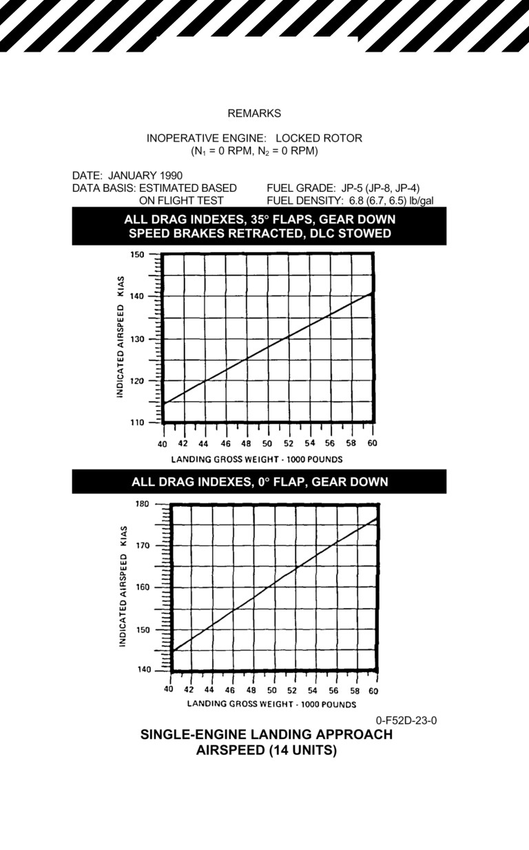
Refer to Single-Engine Landing Approach
Airspeed (page 183)
Military power climb performance
during heavy waveoffs may not ade-
quately arrest high sink rate condi-
tions. Use of full AB provides an
increase in climb performance. Up to
full rudder may be required to counter
AB asymmetric thrust yawing moment
during waveoff or bolter. Do not exceed
14 units AOA during waveoff or bolter.
SINGLE-ENGINE LANDING —
SEC MODE
1. FUEL SHUTOFF (inoperative engine) .
Pull
2. In CV environment .
Divert
3. Refer to Single-Engine Cruise and Engine Trans-
fer to SEC Mode procedures.
If not preparing for CV approach, see step 6.
CONTINUED
176
NAVAIR 01-F14AAP-1B
If divert not possible:
Engine thrust and thrust response can
be severely degraded such that level
flight cannot be maintained in the full-
flap landing configuration. DO NOT
configure for landing until the perfor-
mance test has been accomplished.
If not configured for landing:
4. Perform constant airspeed climb (+5 knots) at 10
units AOA, landing gear up, maneuvering flaps
down (if possible), above 2,000 feet. Minimum
climb required in 30 seconds is as follows:
CHANGE IN ALTITUDE — FEET
MANEUVER
MANEUVER
FLAPS DN
FLAPS UP
2,000 feet
950 feet
900 feet
4,000 feet
800 feet
750 feet
6,000 feet
700 feet
650 feet
CAUTION
If minimum performance test is passed
based on predicted gross weight, do
not lower landing gear and flaps until
predicted gross weight is reached.
CONTINUED
177
NAVAIR 01-F14AAP-1B
Note
Climb performance will improve by 20
feet in
30-second climb for every
1,000-pound gross weight reduction.
Minimum performance criteria is based
on optimum conditions
(day, VMC,
steady deck, experienced aircrew, nor-
mal wind over deck, etc.) and should be
increased for degraded conditions
based on judgment.
5. If minimum performance criteria are not passed
and all options are exhausted (stores jettisoned,
minimum gross weight, and divert not possible),
eject under controlled conditions.
If configured for landing:123
4. Throttle .
MIL
5. Ensure a minimum of 500-fpm rate of climb at 14
units AOA available for CV approach.
When preparing for landing:
Shipboard recovery in single-engine
SEC mode is considered extremely
hazardous and should be conducted
only as a last resort and if the perfor-
mance check is successful.
6. RUDDER AUTH light .
Verify Out
7. Wing sweep .
Set at 20°
CONTINUED
178
Change 1
NAVAIR 01-F14AAP-1B
If hammering
(cavitation) is experi-
enced in the hydraulic system, compo-
nent rupture is imminent. Turn the HYD
TRANSFER PUMP switch (BIDI) OFF.
8. External stores .
Jettison for
Shipboard Recovery
9. Fuel .
Dump or Burn
10. Speedbrakes .
RET (on final approach)
11. LDG GEAR handle .
DN
12. Hook .
As Required
13. Check SAS .
ON
Shore-based landings should be con-
ducted with flaps up. If conditions
warrant a full-flap landing, conduct a
performance test and proceed as in the
case of a ship-board landing.
14. If combined pressure
zero .
Pull AUX FLAP/
FLAP CONTR cb (7G3)
15. Flaps .
DN (shipboard recovery),
As Required (field landing)
16. DLC .
Do Not Engage
17. EMERG FLT HYD .
HIGH (on final,
committed to land)
CONTINUED
179
NAVAIR 01-F14AAP-1B
If combined pressure is zero, do not re-
turn to auto (low) mode once module is
selected on. If module is shut off after
operation commences, it may not re-
start.
18. For landing pattern, use 10 units AOA for pattern
airspeed and do not attempt turns greater than
20° angle of bank.
Extreme caution must be exercised
when performing turns into a dead
engine. Decaying airspeed/increasing
AOA can rapidly result in a situation
where there is not enough rudder
authority to return the aircraft to level
flight and insufficient altitude to effect
recovery.
19. Final approach airspeed .
13 Units (CV)
(field landing, slow to,
15 units AOA, no flaps
at touchdown)
Note
Waveoff should be conducted by rotat-
ing to 14 units (maximum) AOA until a
positive rate of climb is attained.
180
NAVAIR 01-F14AAP-1B
Note
Bolters should be conducted by rotat-
ing to 10_ pitch attitude not to exceed
14 units AOA.
SINGLE-ENGINE CRUISE OPERATIONS
1. FUEL SHUT OFF
handle (inoperative engine) .
Pull
2. If on final approach or landing, refer to Single-
Engine Landing.
When either fuselage tape reaches 4,500 pounds of fuel
or less:
3. WING/EXT TRANS switch .
OFF
Note
The WING/EXT TRANS switch auto-
matically returns to AUTO if the
REFUEL PROBE switch is placed to
ALL EXTEND, DUMP is selected, or
there is 2,000 pounds remaining in the
low side. The WING/EXT TRANS switch
can be reselected to OFF after a
5-second delay, the REFUEL PROBE is
retracted, or DUMP is secured.
4. FEED switch .
Operating Engine Side
When pilot workload permits close monitoring of fuel dis-
tribution:
5. FEED switch .
Inoperative Engine Side
If the fuselage quantity on the inoperative engine side
begins to increase:
6. FEED switch .
Immediately Move
to Operating Engine Side
CONTINUED
Change 3
181
NAVAIR 01-F14AAP-1B
CAUTION
An increase in fuel quantity on the in-
operative engine side indicates that
the sump tank interconnect valve is not
open. Fuel available is limited to the
quantity on the operating engine side.
If the fuselage fuel quantity on the inoperative engine side
begins to decrease:12345
6. FEED switch .
Remain on
Inoperative Engine
7. WING/EXT TRANS switch .
AUTO
8. Refer to appropriate hydraulic system failure.
CONTINUED
182
NAVAIR 01-F14AAP-1B
2.
183
TO