F-14D. FLIGHT MANUAL (2004) - page 15
NAVAIR 01−F14AAD−1
39.1.3.6
Area
39.2.6
MFT and WST Procedures Evaluation
An area is a routine of preflight, flight, or postflight.
An MFT and WST may be used to assist in measuring
the flightcrewmember’s efficiency in the execution of
39.1.3.7
Subarea
normal operating procedures and reaction to emergencies
and malfunctions. In areas not covered by the OFT and WST
A performance subdivision within an area that is
facilities, this may be done by placing the flightcrewmember
covered and evaluated during an evaluation flight.
in an aircraft and administering appropriate questions.
39.1.3.8
Critical Area and Subarea
39.2.7
Grading Instructions
Any area or subarea that covers items of significant
Examination grades shall use a
4.0 scale and be
importance to the overall mission requirements, the marginal
converted to an adjective grade of Qualified or Unqualified.
performance of which would jeopardize safe conduct of the
flight.
39.2.7.1
Open−Book Examination
39.2
GROUND EVALUATION
To obtain a grade of Qualified, an evaluee must obtain
a minimum score of 3.5.
Prior to commencing the flight evaluation, an evaluee
must achieve a minimum grade of Qualified on the
39.2.7.2
Closed−Book Examination
open−book and closed−book examinations. The oral
To obtain a grade of Qualified, an evaluee must obtain
examination is also part of the ground evaluation but may be
a minimum score of 3.3.
conducted as part of the flight evaluation. To assure a degree
of standardization between units, the NATOPS instructors
39.2.7.3
Oral Examination and MFT and WST
may use the bank of questions contained in this chapter in
Procedure Check (If Conducted)
preparing portions of the written examinations.
A grade of Qualified or Unqualified shall be assigned
39.2.1
Open−Book Examination
by the instructor−evaluator.
The open−book examination shall consist of, but not be
39.3
FLIGHT EVALUATION
limited to, the question bank. The purpose of the open−book
examination portion of the written examination is to evaluate
The flight evaluation may be conducted on any routine
the flightcrewmember’s knowledge of appropriate publicaĆ
syllabus flight with the exception of flights launched for
tions and the aircraft.
FCLP and CARQUAL or ECCM training. Emergencies will
not be simulated.
39.2.2
Closed−Book Examination
The number of flights required to complete the flight
The closed−book examination may be taken from, but
evaluation should be kept to a minimum, normally one flight.
shall not be limited to, the question bank and shall include
The areas and subareas to be observed and graded on a flight
questions concerning normal and emergency procedures and
evaluation are outlined in the grading criteria with critical
aircraft limitations. Questions designated critical will be so
areas marked by an asterisk (*). Grades on subareas will be
marked.
assigned in accordance with the grading criteria. Grades on
39.2.3
Oral Examination
subareas shall be combined to arrive at the overall grade for
the flight. If desired, grades of areas shall also be determined
The questions may be taken from this manual and may
in this manner. At the discretion of the squadron or unit
be drawn from the experience of the instructor−evaluator.
commander, the evaluation may be conducted in WST, MFT,
Such questions should be direct and positive and should in no
or COT.
way be based solely on opinion.
39.3.1
Instrument Flight Evaluation
39.2.4
Emergency
Annual NATOPS instrument flight evaluations and the
An aircraft component or system failure or condition
IFR portions of NATOPS flight evaluations, whether conĆ
that requires instantaneous recognition, analysis, and proper
ducted in flight or in an approved simulator, must be
action.
conducted by a NATOPS−qualified pilot or RIO, who is
designated in writing by the unit commanding officer. Such
39.2.5
Malfunction
instrument flight evaluations must be conducted in accorĆ
An aircraft component or system failure or condition
dance with the procedures outlined in the current OPNAĆ
that requires recognition and analysis, but which permits
VINST 3710.
more deliberate action than that required for an emergency.
ORIGINAL
39−2
NAVAIR 01−F14AAD−1
39.4
OPERATIONAL DEPLOYABLE SQUADRONS
2.
Takeoff (pilot)
Pilots and RIOs assigned to operational deployable
3.
Transition to climb schedule.
squadrons will normally be checked as a team, with the flight
evaluation being conducted by the checkcrew flying wing.
39.6.5
Climb and Cruise
RIO commentary will be transmitted on the GCI or CIC
control frequency in use.
1.
Departure (pilot)
39.5
TRAINING AND EVALUATION SQUADRONS
2.
Climb and level−off (pilot)
Units with training or evaluation missions that are
3.
Procedures en route (pilot)
concerned with individual instructor pilot or RIO standardĆ
ization rather than with team standardization may conduct
39.6.6
(*) Approach and Landing
the flight evaluation with the checkcrew−pilot flying wing or
on an individual basis. A pilot may be individually checked
1.
Radar, TACAN (pilot)
with the instructor−evaluator conducting the flight evaluation
from the rear seat. The RIO may be individually checked by
2.
Recovery (pilot).
flying with the instructor−evaluator pilot.
39.6.7
Communications
39.6
FLIGHT EVALUATIONS
1.
Receiving and transmitting procedures (pilot and
The areas and subareas in which pilot and RIOs may be
RIO)
observed and graded for adherence to standardized operating
procedures are outlined in the following paragraphs.
2.
Visual signals (pilot and RIO)
Note
3.
IFF and SIF procedures (RIO).
If desired, units with training missions may
expand the flight evaluation to include evaluation
39.6.8
(*) Emergency and Malfunction
of standardized training methods and techniques.
Procedures.
(*) The IFR portions of the flight evaluation shall be in
In this area, the pilot and RIO will be evaluated only in
accordance with the procedure outlined in the NATOPS
the case of actual emergencies unless evaluation is conducted
Instrument Flight Manual.
in the COT, WST, or OFT.
39.6.1
Mission Planning and Briefing
39.6.9
Postflight Procedures
1. Flight planning (pilot and RIO)
1. Taxi in (pilot)
2. Briefing (pilot and RIO)
2. Shutdown (pilot and RIO)
3. Personal flying equipment (pilot and RIO).
3. Inspection and records (pilot and RIO)
39.6.2
Preflight and Line Operations
4. Flight debriefing (pilot and RIO).
Inasmuch as preflight and line operation procedures
are graded in detail during the ground evaluation, only those
39.6.10
Mission Evaluation
areas observed on the flight check will be graded.
This area includes missions covered in the NATOPS
1. Aircraft acceptance (pilot and RIO)
flight manual, F−14D tactical manual, and naval warfare
publications for which standardized procedures and techĆ
2. Start
niques have been developed.
3. Before−taxiing procedures (pilot).
39.7
RECORD AND REPORTS
39.6.3
Taxi and Runup
A NATOPS evaluation report (OPNAV Form 3710/7)
shall be completed for each evaluation and forwarded to the
39.6.4
(*) Takeoff and Transition
evaluee’s commanding officer only. This report shall be filed
and retained in the individual’s NATOPS jacket. In addition,
1. ATC clearance (pilot)
an entry shall be made in the pilot’s and RIO’s flight
39−3
ORIGINAL
NAVAIR 01−F14AAD−1
logbooks under Qualifications and Achievements" as
To determine the numerical grade for each area and the
follows:
overall grade for the flight, add all the points assigned to the
subareas and divide this sum by the number of subareas
graded. The adjective grade shall then be determined on the
QUALIFICATION
DATE
SIGNATURE
basis of the following scale.
NATOPS
(Date)
(Authenticating
1. 0.0 to 2.19 Unqualified.
EVALUATION
signature)
2. 2.2 to 2.99 Conditionally Qualified.
(Aircraft Model)
(Unit that
3. 3.0 to 4.0 Qualified.
administered
(Crew Position)
evaluation)
Example (add subarea numerical equivalents):
4 + 2 + 4 + 2 + 4
16
=
= 3.20 or Qualified
5
5
39.7.1
Critique
39.8.2
Final Grade Determination
The critique is the terminal point in the NATOPS
evaluation and will be given by the evaluator−instructor
The final NATOPS evaluation grade shall be the same
administering the check. Preparation for the critique involves
as the grade assigned to the flight evaluation. An evaluee who
processing, reconstructing data collected, and oral presentaĆ
receives an Unqualified on any ground examination or the
tion of the NATOPS evaluation report. Deviations from
flight evaluation shall be placed in an Unqualified status until
standard operating procedures will be covered in detail using
a grade of Conditionally Qualified or Qualified is achieved
all collected data and worksheets as a guide. Upon compleĆ
on a reevaluation.
tion of the critique, the pilot and RIO will receive the
completed copy of the NATOPS evaluation report for
39.9
APPLICABLE PUBLICATIONS
certification and signature. The completed NATOPS evaluaĆ
tion report will then be presented to the unit commanding
The NATOPS flight manual contains the standard
officer.
operations criteria for F−14D aircraft. Publications regarding
environmental procedures peculiar to shorebased and shipĆ
39.8
FLIGHT EVALUATION GRADING CRITERIA
board operations and tactical missions are listed below:
Only those subareas provided or required shall be
1. F−14D tactical manuals
graded. The grades assigned for a subarea shall be deterĆ
mined by comparing the degree of adherence to standard
2. NWPs
operating procedures with adjectival ratings listed below.
Momentary deviations from standard operating procedures
3. NATOPS Air Refueling Manual
should not be considered as unqualifying provided such
4. Air Traffic Control NATOPS Manual
deviations do not jeopardize flight safety and the evaluee
applied prompt corrective action.
5. Local Air Operations Manual
39.8.1
Flight Evaluation Grade Determination
6. Carrier Air Operations Manual.
The following procedure shall be used in determining
the flight evaluation grade. A grade of Unqualified in any
39.10 NATOPS EVALUATION QUESTION BANK
critical area and subarea will result in an overall grade of
The following bank of questions is intended to assist
Unqualified for the flight. Otherwise, flight evaluation (or
the unit NATOPS instructor−evaluator in the preparation of
area) grades shall be determined by assigning the following
ground examinations and to provide an abbreviated study
numerical equivalents to the adjective grade for each subarea
guide. The questions from the bank may be combined with
Only the numerals 0, 2, or 4 will be assigned in subareas. No
locally originated questions in the preparation of ground
interpolation is allowed.
examinations. The closed−book examination will consist of
not less than 25 questions nor more than 75 questions. The
1. Unqualified 0.0
time limit for the closed−book examination is 1 hour and 30
2. Conditionally Qualified 2.0
minutes. The requirements for the open−book examination
are the same as those for the closed−book examination,
3. Qualified 4.0.
except there is no time limit.
ORIGINAL
39−4
NAVAIR 01−F14AAD−1
NATOPS EVALUATION QUESTION BANK
1.
The aircraft weighs approximately ________________ including trapped fuel, oil, gun, pilot and RIO.
2.
The aircraft is __________ in length and has a wing span of __________at 20_ and ______________ in oversweep.
3.
The L INLET and R INLET caution lights indicate __________________.
4.
During normal system operation, the status of AICS ramp control is as follows:
SPEED
Ramp Hydraulic Power
M < 0.35
ON/OFF
Restrained by
M 0.35 to 0.5
ON/OFF
Commanded
M > 0.5
ON/OFF
Programmed as a function of
5.
An AICS failure that causes illumination of an INLET and/or RAMP caution light results in the following:
Speed Range
Ramp Resultant
M < 0.35
M 0.5 to 0.9
M > 0.9
6.
During the AICS portion of OBC, simulated variant flight conditions cycle the ____________________________ through
their full range of operation in about_______ seconds. This exercises the _______________________________________
and ensures ________________________________________.
7.
Operation of the L and R AICS is completely independent.
a. True
b. False
8.
AICS anti−ice is available between ________ Mach and ________ Mach.
9.
With the gear handle down and one or more ramps not in the stow position, the ramp light will be illuminated.
a. True
b. False
10.
The installed thrust of the F110−GE−400 engine is ________ pounds at MRT and ________ pounds at MAX A/B.
11.
In SEC mode, both main engine fuel flow and compressor VSVs are scheduled ____________________________ by the
___________, and fan speed is limited __________by the ____________.
12.
A 3−percent increase in windmill rpm can be achieved by selecting ___________.
13.
Nonemergency selection of the SEC mode should be performed in _________________.
39−5
ORIGINAL
NAVAIR 01−F14AAD−1
14.
The augmenter fan temperature control system regulates five parameters of the engine to provide stall−free operation for
any rate of throttle movement throughout the flight envelope. These parameters are:
a.
b.
c.
d.
15.
The engine electrical control subsystem is powered by an engine gearbox−mounted
(ac
or
dc)
alternator
that
contains ______________ separate windings, which are:
a.
b.
c.
d.
16.
What are the two power sources for fan speed limiting?
a.
b.
17.
The backup ignition is powered by the aircraft ______________________bus.
18.
Autorelight logic is provided by the ________________________.
19.
What are the throttle interlocks at the military power detent?
a.
b.
c.
20.
Autothrottle may be preflight ground tested on deck either in ______________________ or _______________________.
Indications that a malfunction exists in the autothrottle system are _________________________________________ or
________________________________________.
21.
List oil pressure readings
a. MRT _______________________psi
b. Minimum at IDLE ___________psi
ORIGINAL
39−6
NAVAIR 01−F14AAD−1
22.
An engine stall with no overtemperature will illuminate the appropriate STALL WARNING light in both PRI and SEC
mode.
a. True
b. False
23.
Normal ranges of nozzle position are:
a. IDLE weight on wheels
b. In−flight MRT
c. MIN A/B
d. MAX A/B
24.
What interlocks must be satisfied to activate the nozzle to the full−open position to reduce residual thrust?
a.
b.
25.
Minimum rpm for ground start of the F110−GE−400 engine is _____________________ percent rpm.
26.
Maximum allowable EGT for ground starting the F110−GE−400 engine is ____________________C.
27.
The starting temperature limits are the same for both ground starts and airstarts.
a. True
b. False
28.
At EGT readings of ______________°C ±10, a warning tone is present in the pilot earphones.
29.
At ____________°C, the EGT chevrons begin to flash.
30.
A hot engine should not be started until EGT is below _______________C airborne.
31.
Zero− or negative−g flight is limited to a maximum of ____________________ seconds in military power or less and
________ seconds in afterburner in order not to __________________________________________.
32.
Above __________________ rpm, the MEC should shut off fuel flow to the F110−GE−400 engine.
33.
If the throttle boost system fails, the throttles automatically revert to manual mode, and the throttle mode switch
returns to MAN.
a. True
b. False
34.
What pilot action is required to reset the boost mode of throttle control subsequent to reversion to the manual mode?
35.
______________________________________________________________ is the controlling parameter for the APCS.
39−7
ORIGINAL
NAVAIR 01−F14AAD−1
36.
Autothrottle engagement range is between _______________ and _________________ percent rpm.
37.
If the autothrottles are disengaged by any means, the AUTO THROT light illuminates for a 10−second duration.
a. True
b. False
38.
Engine rpm must be above ___________ percent to supply sufficient power for the main engine ignition system.
39.
When attempting a crossbleed or normal ground start, the ENG CRANK switch will not reengage if the engine is spooling
down and engine rpm is between ____________ and _____________ percent.
40.
During spooldown airstarts, hung starts in the low rpm range
(less than
45 percent) can be assisted with
___________________________. Hung starts in the mid−rpm range
(50 to
60 percent) can be corrected by
___________________________.
41.
If the IGV linkage breaks, the IGVs assume a
_________________ position, which is near normal for
_________________ power settings.
42.
The number of delta Ps to check on each engine during preflight is ________________________.
43.
During an engine ground fire or abnormal start, be sure that the BACK UP IGNITION switch is in the
______________ position.
44.
The L or R FIRE warning lights illuminate when the respective entire sensing loop is heated approximately
___________°F or when any 6−inch section is heated to approximately_______________F.
45.
What procedures should be followed to check oil level if it was not checked within 5 to 30 minutes after shutdown?
46.
During preflight, the oil sight gauge is always a reliable indicator of oil level.
a. True
b. False
47.
The No. __________ bearing receives priority lubrication in the event of a loss of oil.
48.
During cold starts, oil pressure greater than 80 psi should not be exceeded for more than _____________ minute(s).
49.
The electrical source for the oil pressure indicator is _____________.
50.
The OIL PRESS warning light will illuminate when the pressure drops below ______________ psi and extinguishes when
pressure rises above ___________ psi.
51.
The L or R OIL HOT warning light indicates that the supply oil temperature has exceeded __________________ or the
scavenge pump temperature has exceeded _____________.
52.
The INLET ICE caution light illuminates when ____________ or _______________.
53.
In AUTO, pitot probe heat is available only with weight off wheels.
a. True
b. False
ORIGINAL
39−8
NAVAIR 01−F14AAD−1
54.
Which of the following would result in illumination of the FUEL PRESS caution light?
a. Failure of a motive flow pump.
b. Failure of a main fuel pump stage.
55.
Failure of the second stage on the main engine fuel pump will have what effect on engine operation?
56.
Failure of a motive flow fuel pump will have what effect on the engine and fuel system operation?
57.
The loss of an engine−driven boost pump will have what effect on operation of both engines?
58.
Selecting either AFT or FWD with the fuel FEED switch performs what functions in the fuel system?
a.
ąc.
ąe.
b.
ąd.
ą
59.
The L/R FUEL LOW light illuminates with approximately ________________ pounds remaining in the respective
feed group.
60.
Automatic shutoff of wing and drop tank transfer occurs with WING/EXT TRANS switch in either AUTO or ORIDE.
a. True
b. False
61.
The engine boost pump is powered by ____________________________________________________.
62.
To increase bingo fuel specifications, the engine mode select switch may be placed in ________________________
during descents or ____________________________________________________.
63.
The BINGO caution light illuminates when _______________________________.
64.
Is vent tank fuel quantity included in the fuel totalizer on the AFT and L indicator readings?
65.
When should the FEED switch be activated to FWD or AFT?
66.
What medium is used to actuate the feed tank interconnect valve, wing motive flow shut−off valves, and fuel dump valve?
67.
Wing fuel is transferred by:
a. Engine bleed air
b. Motive flow fuel
68.
The fuel thermistors in the outboard section of the wing tanks perform what function?
69.
The fuel thermistors in fuel cell Nos. 2 and 5 perform these functions when either is uncovered:
a.
ąd.
b.
ąe.
ą
c.
ąą
39−9
ORIGINAL
NAVAIR 01−F14AAD−1
70.
All fuel entering the vent tank is vented overboard through the vent mast in the tailhook attachment fairing.
a. True
b. False
71.
Fuel transfer from the external drop tanks is accomplished by __________________.
72.
External fuel transfer can be checked on the deck by __________ or __________.
73.
Fuel dump is prohibited with speedbrakes open and/or afterburner operation.
a. True
b. False
74.
When the fuel dump circuit is activated, wing and external drop tank transfer is automatically initiated.
a. True
b. False
75.
Is it possible to refuel in flight and accomplish total fuel transfer without electrical power or a combined hydraulic system?
If not, why?
76.
On engine start with the generator switch in normal, the generator is automatically excited and the generator control unit
brings it on the line when engine rpm is approximately ____________________ percent.
77.
_________________ stage bleed air is used for IDG oil ground cooling.
78.
If the thermal cutout decouples the drive clutch to either main generator in flight, the IDG may be recoupled (reset) a
maximum of three times.
a. True
b. False
79.
Failure of either ac generator automatically connects the left and right main ac buses to the operative generator.
The cockpit indicator will be a __________________ caution light.
80.
The emergency generator is powered by _____________________.
81.
If the emergency generator switch is in NORM, it will come on the line automatically when ______________________
________________________________________________________.
82.
When operating on the emergency generator, the cockpit lighting available consists of _______________________ and
___________________________.
83.
A single engine−driven pump on the left powers the combined hydraulic system and a single engine−driven pump on the
right powers the flight hydraulic system.
a. True
b. False
ORIGINAL
39−10
NAVAIR 01−F14AAD−1
84.
If the pilot extinguishes the MASTER CAUTION light after a failure of one main hydraulic system, failure of the other
system (will or will not) illuminate the MASTER CAUTION light. Why?
85.
List the requirements for operation of DLC.
86.
With the left engine shut down in flight and
0 percent windmill rpm, the combined hydraulic system can be
powered by ______________________________.
87.
With total loss of fluid from either main hydraulic system, the hydraulic transfer pump will ____________________
___________________________________________________________________________________________.
88.
The cockpit handpump will charge the brake accumulator in flight if________________________________________
__________________________________________________.
89.
Loss of all hydraulic fluid from the flight hydraulic system will mean loss of power to the right inlet ramps.
a. True
b. False
90.
With loss of the combined hydraulic system (combined system pressure zero), the main flaps are powered by
___________________ and the auxiliary flaps are __________________________________________________.
91.
With the landing gear emergency blown down, the nosewheel steering and normal brakes will operate after touchdown.
a. True
b. False
92.
The outboard spoiler module uses combined system fluid.
a. True
b. False
93.
Outboard spoilers are inoperative with wing−sweep angles aft of ___________.
94.
The outboard spoiler module thermal cutout is inhibited when ______________________________________________
_______________________________________________.
95.
The ON−OFF flag in the spoiler window of the hydraulic indicator indicates:
a. The outboard spoiler module is energized.
b. The outboard spoiler system is pressurized.
96.
With loss of the combined hydraulic system
(combined system pressure zero) the inboard spoilers will:
_________________________________.
97.
The backup flight control module powers the _____________ and the _____________.
98.
With the backup flight control module switch in AUTO, the module is automatically energized when
_______________________________________________________________________.
99.
The backup flight control module switch has three positions: AUTO, ___________________ and _________________
___________________________.
39−11
ORIGINAL
NAVAIR 01−F14AAD−1
100. The backup flight control module operates in the high−speed mode when ____________________________________
___________________.
101. Operational status of the backup flight control module is indicated in the cockpit by ___________________________
____________________________________________________________________________________________.
102. DLC requires an operable outboard spoiler module.
a. True
b. False
103. Failure of either the combined or flight hydraulic system will have what effect on wing−sweep?
104. On the wing−sweep indicator, there are three position indicators. These show
______________________________
__________________ and ___________________ wing−sweep position.
105. The aircraft is being operated with the wings aft of the forward limit. The wing−sweep control mode indicator reads MAN.
If speed is now increased beyond where the wing−sweep angle and forward limit coincide, the control mode indicator
will read _______________ and the wings will __________________.
106. The most forward wing−sweep angle allowed in bomb mode is __________.
107. The emergency wing−sweep mode is a manual method of positioning the wings. This method incorporates locks every
_____________ from 20_ to 68_ to prevent random wing movement in this mode.
108. Illumination of the WING SWEEP warning light means: _________________________________________________
____________________________________________________________________________________________.
109. Appearance of the W/S warning legend on the MFD means: ______________________________________________
____________________________________________________________________________________________.
110.
Transient failures in the CADC may be reset by: ________________________________________________________
____________________________________________________________________________________________.
111.
The CADC is self−tested in _____________________________.
112.
List the caution, advisory, and warning lights activated by the CADC directly or via the DFCS:
a.
ąe.
b.
ąf.
ą
c.
ąg.
ą
d.
ąh.
ą
113.
When instrument test has been selected on the MASTER TEST panel, the EIG indications after 5 seconds are:
a. RPM
b. EGT
c. FUEL
d. FLOW
ORIGINAL
39−12
NAVAIR 01−F14AAD−1
114.
A degraded mode of EIG operation is indicated by ___________________________.
115.
Maneuver flaps can be lowered at any wing−sweep angle between 20° and ______________________.
116.
The maneuvering flap thumbwheel will lower the main flaps ______________, the auxiliary flaps ____________,
and the slats ____________, Use of the maneuvering devices (does or does not) put more restrictive g limitations on the
aircraft.
117.
What is the meaning of the following (besides CADC failure) ?
a. FLAP caution light
b. REDUCE SPEED warning
(1)Ą
(2)Ą
(3)Ą
118.
Power for emergency extension of the landing gear is supplied by___________________________________________
______________________________________________________________________________________________.
119.
The minimum bottle pressure for accomplishing emergency extension of the landing gear is _____ psi but minimum
preflight bottle pressure is ________ psi at 70_ F (21_ C).
120. Full lateral trim in the direction of stick displacement will reduce maximum spoiler deflection to
_____________ on that side.
121. Full slat asymmetry of 17_ can result in an out−of−control situation at _________ units AOA or greater, even with
55_ of spoilers available.
122. The rudder pedal shaker is armed with main flaps greater than _________________ _ and the ________________
computer operating.
123. With DLC engaged, full−up DLC positions the inboard spoilers at _______________ _ and the horizontal stab trailing
edges ______________.
124. The initial position for spoilers when DLC is engaged is _____________________.
125. The correct positioning for stabilizers when DLC is given a full−down command (from trim) is _________________
trailing edge ___________________.
126. Full rudder throw of ± _________________________ corresponds to ± inches of rudder pedal travel.
127. Control surface authority of the stability augmentation system is:
Pitch ±
_.
Roll ±
_.
Yaw ±
_.
128. The gear handle is down and the three gear position indicators show the gear down, but the transition light is illuminated.
What does this indicate and what action should be taken?
39−13
ORIGINAL
NAVAIR 01−F14AAD−1
129. The ANTI SKID SPOILER BK switch is OFF and the BRAKE light is illuminated. This would indicate:
a.
b.
130. The BRAKE light (ANTI SKID SPOILER BK switch OFF) operates only when the brakes are depressed or the parking
handle is pulled.
a. True
b. False
131. The two procedures for lowering the launch bar are: ________________________ or __________________________.
132. Nosewheel steering cannot be engaged until weight is on wheels.
a. True
b. False
133. With the nosewheel <70°, the nosewheel assumes the position commanded by the rudder pedals when nosewheel steering
is engaged.
a. True
b. False
134. BLEED DUCT light indicates temperatures in excess of ________________ °F between engine and primary heat
exchanger or greater than ___________________°F between primary heat exchanger and the ECS turbine.
135. The ram air door can be opened only if the ___________ or ___________ button is depressed on the ECS control panel.
136. The ram air door automatically closes with selection of L ENG, R ENG, or BOTH ENG on the ECS control panel.
a. True
b. False
137. The ram air door requires ____________ seconds to go full open.
138. The RIO has a low−cockpit−pressure caution light (CABIN PRESS) that illuminates if ______________________
or _______________________.
139. With the OBOGS light on, each flightcrewmember should have _______________ hours of oxygen at 20,000 feet
(8,000 feet cabin altitude).
140. Pulling the emergency oxygen actuator releases gaseous oxygen charged to psi and will provide approximately
a _______________ minute supply.
141. Windshield rain removal is accomplished by blowing 390° F air over the outside of the windshield. If the temperature
sensor detects an overtemperature condition, the WSHLD HOT advisory light will illuminate
and ________________________.
142. Maximum allowable headwind for the open canopy is ____________________ knots.
ORIGINAL
39−14
NAVAIR 01-F14AAD-1
143. When the canopy is jettisoned, the sill locks are released by _______________________________________________.
144. The canopy pneumatic reservoir must be serviced by ground servicing unit.
a. True
b. False
145. The pilot can tell the position of the command ejection lever by ____________________________________________.
146. The RIO can eject both himself and the pilot with EJECT CMD handle set to PILOT.
a. True
b. False
147. The pilot can eject both himself and the RIO with the EJECT CMD handle set to MCO.
a. True
b. False
148. In the event the canopydoes not separate from the aircraft when eitherflightcrewmember hasinitiated ejection, “through
the canopy” ejection will not occur.
a. True
b. False
149. There are ___________________safety pins per ejection seat.
150. Command ejection by either flightcrewmember will eject the RIO in ____ seconds and the pilot ________ seconds later.
151. For a high-altitude ejection, the seat is allowed to free-fall to
_____________________ feet.
152. All exterior lighting controls except for the ____________ light are located on the MASTER LIGHT panel on the pilot
console, and the exterior lights master switch on the outboard throttle.
153. Whenthewingsaresweptaftof__________,the_____________positionlightsare disabledandtheglove positionlights
are operable.
154. When the ANTI-COLLISION light switch is ON, the ________________ position lights flasher switch is disabled.
155. A proper indicator lights test has the MASTER CAUTION light on steady.
a. True
b. False
156. The RIO can monitor SW tones by selection of ___________ position on the ICS panel.
157. The standby attitude indicator is capable of providing reliable attitude information within _______________ for up to
___________ minutes after a complete loss of power.
158. On deck, the allowable error between the pilot and RIO altimeter readings is ____________ feet at field elevation.
39-15
CHANGE 1
NAVAIR 01−F14AAD−1
159. The angle−of−attack indicator is checked during ______________ and the indexer during ____________. Proper indi−
cations are:
a. Indicator
b. Indexer
160. In the landing configuration, 15 units AOA is equivalent in airspeed for:
a.
48,000 pound (DLC not engaged) =
KIAS
b.
48,000 pound (DLC engaged/neutral) =
KIAS
c.
50,000 pound (DLC not engaged) =
KIAS
161. With an airspeed indicator failure, list the angle of attack to fly for the following conditions (drag index 8):
a. Catapult
_____________________________________________.
b. Climb (MIL) SL_____________________________________________ to combat ceiling.
c. Cruise at OPT. ALT.________________________________________________________.
d. Endurance a OPT. ALT.______________________________________________________.
162. Stores jettison is controlled by which aircraft system?
163. ACM jettison requires MASTER ARM ON.
a. True
b. False
164. Selective jettison can be completely controlled by either flightcrewmember.
a. True
b. False
165. In the emergency jettison mode, the weight−on−wheels interlock is bypassed.
a. True
b. False
166. Emergency jettison mode will jettison Sidewinders.
a. True
b. False
167. Sidewinder is jettisoned by firing the motor and safing the warhead.
a. True
b. False
ORIGINAL
39−16
NAVAIR 01−F14AAD−1
168. The pretaxi (weight−on−wheels) OBC master test is a complete check of the SMS.
a. True
b. False
169. Selection of any pulse dogfight mode automatically provides stab out aircraft reference.
a. True
b. False
170. The pilot must clear maintenance display prior to running OBC for current test results
a. True
b. False
171. For normal UHF operation with the ARC−182, the AM/FM switch should be in the __________________________
position.
172. With track files established in TWS, the HUD and MFDs provide the pilot complete steering information to the centroid
of the targets.
a. True
b. False
173. The navigation system may be updated by five methods; they are:
a.
ąd.
b.
ąe.
ą
c.
ąą
174. In TACAN BIT, the range and bearing on the HSD and BDHI should indicate _____________________ nm and
__________.
175. The target designator is valid to ± __________ off the nose.
176. With MASTER ARM OFF, the HUD and VDI armament legend will appear with _______________________.
177. To obtain an attack presentation, the air−to−air button must be selected on the PDCP.
a. True
b. False
178. The COOLING AIR light refers to air cooling out of tolerance while the SENSOR COND light indicates liquid cooling
out of tolerance.
a. True
b. False
39−17
ORIGINAL
NAVAIR 01−F14AAD−1
179. The PTID is oriented to ___________________ north, with selection of GND STAB on the PTID mode switch.
180. Which of the following presentations are available to the pilot:
a. IRSTS
b. PS
c. PDS
d. All of the above.
181. A _____________ acronym indicates a failure of the SMS, thus preventing normal separation of stores in any launch
mode.
182. The RADAR COOLING switch in the RIO cockpit controls liquid coolant to __________________.
183. Hostile area altitude is entered in the _______ pseudo file to properly reject altitude line return.
184. Wind is automatically computed by the system in the INS mode.
a. True
b. False
185. A wind of 35 knots and 057_ relative to the duty runway represents a headwind component of ________________
knots and crosswind of _________ knots.
186. A blinking SHOOT cue indicates ______________________________________________________________.
187. Hydraulic power to drive the gun comes from the ___________________________________________ system.
ORIGINAL
39−18
NAVAIR 01−F14AAD−1
PART XI
Performance Data
For aircraft performance data and charts, refer to NAVAIR 01−F14AAP−1.1.
95 (Reverse Blank)
ORIGINAL
NAVAIR 01−F14AAD−1
CHAPTER 40
Tactical Imaging Set
AN/AVX−3
40.1
AN/AVX−3 TACTICAL IMAGING SET
varies depending on the selected operating mode. Display
brightness is controlled via menu selection.
The Tactical Imaging Set, as installed in the F14D
aircraft, captures, digitizes, and compresses imagery from an
40.1.2
Image Transceiver
external RS 170 video source, then stores and/or transmits it
over a secure communications link. The external video
Image Transceiver functions are controlled by a
source is typically a camera/video system such as the nose
microprocessor. The Image Transceiver also has two
mounted Television Camera System (TCS), Low Altitude
Personal Computer Memories Card International AssociaĆ
Navigation and Targeting System for Night (LANTIRN),
tion (PCMCIA) card slots. The microprocessors executable
Head Up Display (HUD) camera, or other similar systems.
program firmware is stored on an 8 Mbyte flash random
Maximum image capture rate is 4 images/second. The
access memory, called the Program card, in slot 1 (left slot).
Tactical Imaging Set can also receive images transmitted by
Upon power up or reset, the firmware is loaded into 6 Mbytes
other Tactical Imaging Sets or compatible systems (such as
of the Image Transceiver 32 Mbyte image memory. The
ground or base stations). Selected images can be displayed on
remaining
26 Mbytes of image memory is allocated for
the forward
(Video Display Indicator−VDI) and/or aft
storage of uncompressed image frames. The image memory
(Programmable Tactical Information Display − PTID) cockĆ
is volatile, and so stored image frames are lost when power
pit display. The Tactical Imaging Set converts standard
is removed. The RCU sends RS−232 serial commands to
National Television Standards Committee (NTSC) video to
this microprocessor to direct the functions of the Image
allow viewing of still−frame
(single−image) imagery or
Transceiver.
recorded video.
The Image Transceiver accepts an RS 170 format video
The Tactical Imaging Set consists of a Remote Control
input from the VTR (or an external video source via the
Unit
(RCU), Image Transceiver, Video Tape Recorder
VTR), digitizes the video to create an image frame, and
(VTR), Interface Box, and four interconnecting cables (not
passes the image frame to an image buffer for output to the
including connecting aircraft wiring). The RCU mounts in
aircraft cockpit display. The image memory stores selected
the aft cockpit at the inboard front of the right side console.
image frames. Image frames stored in memory can be
The Image Transceiver, VTR, Interface Box, and cables are
randomly accessed for viewing and/or cropping before
mechanically mounted as one unit, called the Naval Airborne
compression. An image compressor (software algorithm)
Video Recorder and Image Transceiver (NAVRIT) Unit,
reduces the size of image frames selected to be stored and
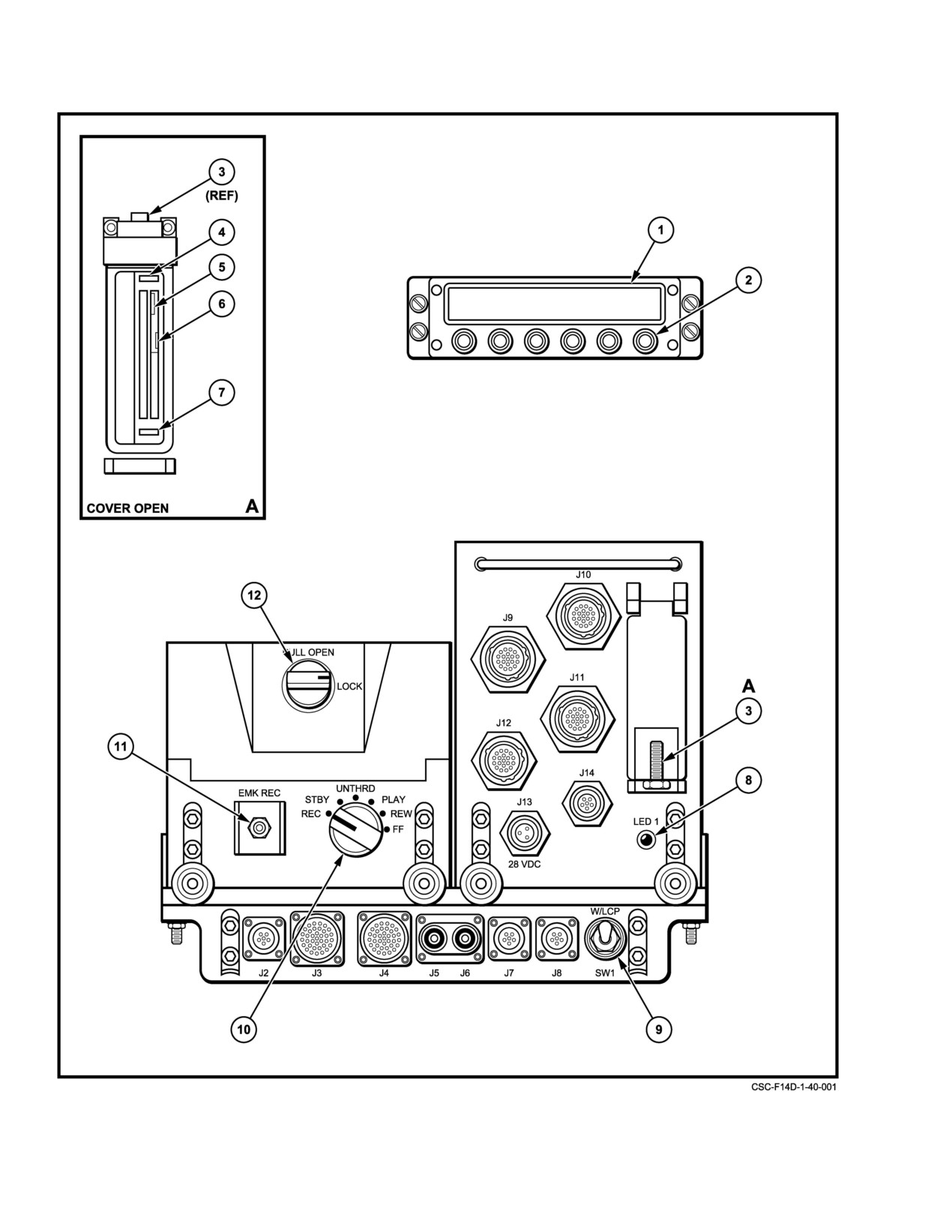
which is mounted in bay 2221−3. Controls and indicators are
routes them to a 4 Mbyte non volatile static random access
shown in Figure 40−1.
memory (SRAM) PCMCIA card, called the Image card, in
slot
0 (right slot) for storage or transmission. The stored
40.1.1
Remote Control Unit (RCU)
image frame includes a clock time code.
The RCU interfaces with the Image Transceiver via an
40.1.3
Video Tape Recorder (VTR)
RS−232 serial bus to enable the Radar Intercept Officer to
remotely control the Image Transceiver functions. ComĆ
The VTR is an airborne video recorder that can record
mand signals are sent from the RCU to the Image TransĆ
and play back up to 2 hours of information on a standard
ceiver, and data is sent from the Image Transceiver to the
Hi 8 format cassette tape. It contains an internal heater to
RCU for display. The RCU display contains 2 lines of 24
prevent condensation. The VTR front panel controls are
green, night vision compatible, alphanumeric characters
disabled; thus all VTR control is remotely performed. RS 422
each. The top line provides status and messages. The bottom
serial command signals are sent from the Image Transceiver
line provides a command menu. The command menu defines
to the VTR, and VTR status data is sent from the VTR to the
the functions of six pushbutton switches located below the
Image Transceiver. Discrete control signals from the aft
display. The command menu, and thus the switch functions,
cockpit Sensor Control Panel are sent to the VTR via the
40−1
ORIGINAL
NAVAIR 01−F14AAD−1
Figure 40Ć1.ĄTactical Imaging Set Controls and Indicators (Sheet 1 of 2)
ORIGINAL
40−2
NAVAIR 01−F14AAD−1
INDEX
NAME
FUNCTION
1
Display (RCU)
48−character alphanumeric display consisting of 2 rows of
24 characters each. Upper row shows operating status.
Lower row identifies functions of switches.
2
Switches (RCU)
Six pushbutton switches. Functions are as defined by lower row of
display.
3
PCMCIA Card Cover Latch
Opens/closes cover for PCMCIA card compartment.
(Image Transceiver)
4
Image Card Release Button
Releases image card for removal.
(Image Transceiver)
5
R−W/WP switch
Permits (R−W) or prevents (WP) recording (writing) on image card.
(Reading of image card is always permitted.)
6
LOCKED latch (Image Card)
Latches and unlatches image card battery compartment.
7
Program Card Release Button
Releases program card for removal.
(Image Transceiver)
8
LED 1 lamp (Image Transceiver)
Indicates +28 VDC power is applied to Image Transceiver.
9
SW1 switch (Interface Box)
Selects video output level.
UP ć nominal 2.2 V (for use with LANTIRN Control Panel installed)
DOWN ć nominal 1.25 V (for use with LANTIRN Control Panel not installed)
10
REC/STBY/UNTHRD/PLAY/
Non−functional
REW/FF control (VTR)
11
EMK REC switch (VTR)
Non−functional
12
PULL OPEN/LOCK latch (VTR)
Opens/closes VTR cassette compartment.
Figure 40−1. Tactical Imaging Set Controls and Indicators (Sheet 2 of 2)
Interface Box. Discrete status signals for certain VTR modes
available commands which are selected using the correĆ
are also sent to the Sensor Control Panel Interface Box.
sponding six pushbutton switches below the display.
40.1.4
Interface Box
1. In bay 2221−3:
a. Ensure Program card is installed in Image TransĆ
The Interface Box provides mechanical mounting for
ceiver slot 1 (left slot).
the VTR and Image Transceiver. Additionally, it provides
electrical connections for dc input power, and connections
b. Ensure formatted Image card is installed in
and switching for digital and video input and output signals.
Image Transceiver slot 0 (right slot).
The Interface Box also modifies the RS 170 video to make
c. Ensure tape cassette is not record protected (red
it compatible with the cockpit displays.
tab should not show) and is installed in VTR.
40.2
OPERATING INSTRUCTIONS
Note
40.2.1
Powerup Sequence
The VTR can record on either Hi 8 or standard
Power up is accomplished using the aft cockpit Sensor
8 mm tape; however, image quality can be subĆ
Control Panel. Once power is applied, the Remote Control
stantially degraded when using standard tape.
Unit
(RCU) controls all functions, although the Sensor
d. Set Interface Box SWl switch as appropriate up
Control Panel can control some Video Tape Recorder (VTR)
if LANTIRN Control Panel is installed; down if
functions. The top line of the RCU display shows status and
LANTIRN Control Panel is not installed.
data. The bottom line of the RCU display shows up to six
40−3
ORIGINAL
NAVAIR 01−F14AAD−1
2.
Set aft cockpit Sensor Control Panel selector to
5. Boot up menu appears.
STBY. RCU displays following sequence:
CS:LOC=###### SND=@@@@@@
PHOTOTELESIS
Ok
Ext NiteDay
Where ###### is the local call sign and @@@@@@ is
PHOTOTELESIS
the first entry in the send to call sign directory. (These
entries can be changed using the Settings menus.)
RCU 403
then
6. Press switch corresponding to desired display
brightness level (if current level is satisfactory, do
Waiting ATR startup
not press a switch):
Unit is
EXT−Not used
Waiting for ATR startup
NITE−Nighttime level from Settings menus
3.
After Image Transceiver startup, the following mesĆ
DAY−Daytime level from Settings menus
sage sequence appears:
RCU RESET
7. Press OK switch. Main menu appears at currently
selected brightness level.
PHOTOTELESIS
S=### H=@@@ R=&&& %+:$$$
RCU 403
BrstSnapSet ViewVoc Send
4.
The following message should NOT appear. If it
does appear, there is no Image card in slot 0, or the
Where ### is the number of image frames in the send queue,
Image card installed is not formatted.
@@@ is the number of image frames in the hold queue,
&&& is the number of image frames in the receive queue, %
UNREADABLE IMAGE CARD
is the VTR mode (S = standby, U = unthreaded, P = playback,
flashing R =recording, all others = blank), ± is either a ć or
Ok
Fmt
a + indicating tape location is before or after the reset point,
and $$$ is the VTR tape counter time in minutes. When the
Note
system is in data mode (voice communication disabled), the
Pressing OK switch enables process to proceed
&&& field flashes. (Specific switch functions displayed may
without resetting, but results are unpredictable.
vary depending on previous actions; for example, when the
send and hold queues are empty, the SEND switch label is not
If message appears, either:
displayed.).
a.
(1) Install formatted Image card and simultaĆ
Note
neously press OK and FMT switches to reset
If a value in a field is greater than 999, the display
RCU and Image Transceiver. Following message
shows ***.
sequence appears:
40.3
RESETTING RCU AND
RCU RESET
IMAGE TRANSCEIVER
PHOTOTELESIS
The RCU and Image Transceiver may be reset
(rebooted) at any time by simultaneously pressing the two
RCU 403
outermost switches. When this is done, the following
message sequence appears:
ATR RESET
or
Note
b. (2) Ensure Image card is installed, and press
The hold and compress queues are erased during
FMT switch to format card. Following message
reset.
appears:
Formatting SRAM card
CHANGE 1
40−4
NAVAIR 01−F14AAD−1
ATR RESET
Main
Ok
b
PHOTOTELESIS
Send to Call Sign
$
Modify Call Sign
RCU−403
b
Send/Delete Function
$
Edit Call Sign
Unit is
b
Waiting for ATR Startup
Capture Rate
RCU RESET
b
PHOTOTELESIS
Capture Time
RCU−403
b
Automatic Transmit
CS:LOC=###### SND=@@@@@@
b
Ok
Ext NiteDay
Compression Method
Where ###### is the local call sign and @@@@@@ is the
b
first entry in the send to call sign directory.
[Wavelets] Compression Ratio
Pressing the OK switch displays the Main menu.
b
40.4
SETTINGS MENUS
[JPEG] JPEG Quality Factor
The Settings menus are used to modify configuration
b
parameters for capturing, compressing, transmitting, and
[PTC] PTC Compression Quality
receiving image frames, as well as other system level
b
functions. The Settings menus are accessed and processed in
sequence from the Main menu (by pressing the SET switch)
PTAC Quickstart
as shown in Figure 40−2.
b
40.4.1
Settings Menus’ Format
Local Call Sign
The Settings menus follow the general format:
b
Display Brightness
PARAMETER:
#######
b
End BackSet Fld PrevNext
Image Dimension
Where ####### (flashing) is the value of the parameter being
b
set. Switch functions vary somewhat among menus, and are
explained as each menu is described.
Comms Cable ID
b
Note
EIS Configuration
The FLD, PREV, and NEXT switches are used to
b
cycle through sets of fields or values. When the
Date and Time
last entry in the set is displayed and the FLD or
NEXT switch is pressed, the first entry in the set
b
is displayed. When the first entry in the set is disĆ
Format SRAM CardĂă
$
Waveburst Version Number
played and the PREV switch is pressed, the last
entry in the set is displayed.
Figure 40Ć2.ĄSettings Menus Sequence
40−5
ORIGINAL
NAVAIR 01−F14AAD−1
40.4.2
Send−to−Call−Sign−Menu
PREV − Change currently displayed call sign to previous
call sign in directory
This menu is used to select/deselect the call signs to be
included in the next transmission. It provides access to
NEXT − Change currently displayed call sign to next call
submenus, which are used to maintain the call sign directory.
sign in directory
The menu contains one value field. When selected, the first
call sign in the directory is listed whether or not it is selected
for transmission. The directory can be stepped through using
40.4.4
Edit Call Sign Menu
the NEXT switch, and each entry can be selected or
deselected, as desired. The displays for a call sign value differ
This menu is used to change the name of an existing
slightly depending on whether that value is selected or not
call sign, including a newly added call sign (000000). Each
selected.
character in the call sign is considered a separate value field.
Valid entries for each character are numerals, upper case
letters, and blanks (H, located in sequence between Z and 0).
For a selected call sign value:
Blanks are not permitted within the body of the call sign;
SENDTO CALLSIGN <######>
however, if a call sign has less than 6 characters, trailing
blanks must be added to complete the 6 character call sign.
End Mod Set Yes No Next
Trailing blanks appear on the display only when the call sign
value field is being edited.
For a non−selected call sign value:
MODIFY CALLSIGN ćĂ######Ăāć
SENDTO CALLSIGN ćĂ######Ăāć
Ok
Fld PrevNext
End Mod Set Yes No Next
OK − Return to Modify Send to Call Sign menu
END − Return to Main menu
FLD − Select next field in call sign
MOD − Display Modify Call Sign menu
SET − Select next menu in sequence
PREV − Change currently selected call sign character to
previous letter or number
YES − Select call sign
NEXT − Change currently selected call sign character to
NO − Deselect call sign
next letter or number
NEXT − Change currently displayed call sign to next call
sign in directory
40.4.5
Send/Delete Function Menu
This menu is used to toggle the send/delete mode
40.4.3
Modify Call Sign Menu
parameter on or off. In send/delete mode, captured images
This menu is used to add a new call sign to the directory
are deleted as they are sent. With send/delete mode turned
or delete an existing call sign from the directory. It also
off, images are copied to the receive queue as they are sent.
provides access to the Edit Call Sign menu, which is used to
Valid values are YES and NO.
define a newly added call sign.
SEND AND DELETE: ###
MODIFY CALLSIGN ćĂ######Ăāć
End BackSet Next
DoneDel New EditPrevNext
END − Return to Main menu
DONE −Return to Send to Call Sign menu
BACK− Display Send−to Call Sign menu
DEL − Delete the current call sign from the directory
SET − Display Capture Rate menu
and display the next value (if no next value,
default is 000000)
NEXT − Toggle send and delete mode value
NEW − Create new unselected call sign with value of
000000 (if value 000000 already exists, switch
40.4.6
Capture Rate Menu
has no effect)
This menu is used to change the time interval between
image captures in burst mode. Valid values range from 0.1 to
EDIT − Display Edit Call Sign menu
ORIGINAL
40−6
NAVAIR 01−F14AAD−1
999.0. Values are incremented or decremented in 0.1−second
40.4.8
Max Key Time
steps when the value is less than 1 second, and in 1−second
This menu is used to change the duration of time that
steps when the value is greater than 1 second. Incrementing
the Tactical Imaging Set transmits image data to a receiving
once from 999.0 or decrementing once from 0.1 disables
station. This menu allows the maximum transmitting time to
burst mode and enables single shot mode. In this case, the
be set between 10 and 180 seconds, using the change interval
value field indicates SINGLESHOT.
of 1 second. The carrier DCRS stations are programmable
and are set for a Max Transmit Time of 30 seconds. The
Note
Tactical Imaging Set default setting is
30 seconds. The
Tactical Imaging Set will always boot to the last set Max
The capture rate can be set to 0.1 or 0.2 seconds/
image; however, these settings are below the
Transmit Time.
Tactical Imaging Set minimum capture rate
MAX KEY TIME
## SECS
value (fastest capture). If the capture rate is set to
0.1 or 0.2 seconds/image, the Tactical Imaging
End BackSet
PrevNext
Set will capture image frames at its fastest speed,
END − Return to Main menu
which is approximately 0.28 second/image in
capture/hold mode. In capture/send mode, the
BACK− Display Capture Time menu
minimum capture rate value is substantially
higher due to the compression required to transĆ
SET −
Display Automatic Transmit menu
fer image frames to the send queue.
PREV − Decrement currently displayed menu
CAPTURE RATE:
##### SEC
NEXT − Increment currently displayed value
EndąBackSet
PrevNext
END − Return to Main menu
40.4.9
Automatic Transmit Menu
BACK− Display Send/Delete menu
This menu is used to toggle the capture mode
parameter between capture/hold and capture/send modes. In
SET − Display Capture Time menu
capture/hold mode, captured images are placed in the hold
queue. In capture/send mode, captured images are placed in
PREV − Decrement currently displayed
the compress queue for transmission. Valid values are
NEXT − Increment currently displayed value
CAPT&HOLD and CAPT&SEND.
AUTO TRANSMIT:
#########
40.4.7
Capture Time Menu
End BackSet
PrevNext
This menu is used to change the duration of image
END − Return to Main menu
captures in burst mode. Valid values range from 001 to 999.
Values are incremented or decremented in 1−second steps.
BACK− Display Capture Time menu
Incrementing once from 999 or decrementing once from 001
selects continuous capturing. In this case, the value field
SET − Display Compression Method menu
indicates CONTINUOUS.
PREV − Toggle automatic transmission mode value
CAPTURE TIME
### SECS
End BackSet
PrevNext
NEXT − Toggle automatic transmission mode value
END − Return to Main menu
40.4.10 Compression Method Menu
BACK− Display Capture Rate menu
This menu is used to select the compression method
parameter. Valid values are WAVELET, JPEG, and PTC.
SET − Display Max Key Time menu
(PhotoTelesis Classic (PTC) compression is used mainly for
PREV − Decrement currently displayed value
compatibility with older analysis systems.)
NEXT − Increment currently displayed value
40−7
CHANGE 1
NAVAIR 01−F14AAD−1
BACK− Display Compression Method menu
COMPRESS METHOD:
#######
End BackSet
PrevNext
SET − Display PTAC Quick Start menu
END − Return to Main menu
JPEG − JPEG Quality Factor menu
BACK− Display Automatic Transmit menu
FIX − Select fixed ratio parameter entry
SET − Display next menu depending on current comĆ
PREV − Decrement compression ratio value
pression method value:
NEXT− Increment compression ratio value
WAVELET − Compression Ratio menu
PTC − PTC Compression Quality menu
40.4.12 PTAC Quick Start Menu
PREV − Select previous compression method value
This menu is used to toggle the PhotoTelesis Tactical
NEXT − Select next compression method value
(PTAC) quick start parameter on or off. Valid values are OFF
and ON. The parameter indicates whether the PTAC protocol
used during transmission attempts to verify established
40.4.11 Compression Ratio Menu
connections before attempting to transmit images.
This menu is used to select the compression ratio
PTAC QUICK START:
###
parameter when using Wavelet compression. Compression
ratio can be selected from fixed ratios of from 10:1 to 75:1
End BackSet
PrevNext
in increments of 5, or a specific (variable) ratio between 10:1
and 150:1 can be selected by incrementing or decrementing
END − Return to Main menu
the displayed value in steps of 1.
BACK− Display previous menu depending on current
compression method value:
For fixed compression ratio values:
WAVELET − Compression Ratio menu
COMPRESSION RATIO: ### :1
JPEG − JPEG Quality Factor menu
End BackSet Var PrevNext
PTC − PTC Compression Quality menu
END − Return to Main menu
SET − Display Local Call Sign menu
BACK− Display Compression Method menu
NEXT− Toggle quick start on/off value
SET − Display PTAC Quick Start menu
VAR − Select variable ratio parameter entry
40.4.13 Local Call Sign Menu
PREV − Select previous fixed compression ratio value
This menu is used to modify the call sign associated
with the Tactical Imaging Set. Each character in the call sign
NEXT− Select next fixed compression ratio value
is considered a separate value field. Valid entries for each
character are numerals, upper case letters, and blanks (4,
For variable compression ratio values:
located in sequence between Z and
0). Blanks are not
permitted within the body of the call sign; however, if the call
COMPRESSION RATIO: ### : 1
sign has less than 6 characters, trailing blanks must be added
End BackSet Fix PrevNext
to complete the
6 character call sign. Trailing blanks
END − Return to Main menu
CHANGE 1
40−8
NAVAIR 01−F14AAD−1
appear on the display only when the call sign value field is
BACK − Display Brightness menu
being edited.
SET − Display View Communications Cable
LOCAL CALLSIGN ćĂ######Ăāć
Identification menu
End BackSet Fld PrevNext
PREV − Toggle image dimension parameter value
END − Return to Main menu
NEXT − Toggle image dimension parameter value
BACK− Display PTAC Quick Start menu
40.4.16 View Communications Cable Identification
SET − Display Brightness menu
Menu
This menu is used to view the type communications
FLD − Select next field in call sign
cable connected to the Image Transceiver. (The cable code
PREV − Change currently selected call sign character to
is hard−wired into the cable connection.) No changes can be
previous letter or number
made from this menu. Normal value is KY−58 DATA.
CABLE: #################
NEXT − Change currently selected call sign character to
next letter or number
End
BackSet
END − Return to Main menu
40.4.14 Display Brightness Menu
BACK− Display Image Dimension menu
This menu is used to set RCU display brightness level
for daytime or nighttime viewing, Valid values are
SET − Display EIS Configuration menu
EXTERNAL (not used), DAY, and NIGHT.
40.4.17 EIS Configuration Menu
ADJUST DISPLAY: ########
This menu is used to change the internal Encryption
End BackSet Dim Brt Next
Interface Subsystem (EIS) configuration file. Viewing file
names and exiting the menu does not change the configuraĆ
END − Return to Main menu
tion file. The file is changed only by loading a new file. EIS
BACK− Display Local Call Sign menu
files are stored on the Program Card. To load a configuration
file, use the PREV and/or NEXT switches such that the name
SET − Display Image Dimension menu
of the desired file is displayed, then press the LOAD switch
to reboot. Normal value is EIS 0001.INI.
DIM − Decrease brightness of display for selected DAY or
NIGHT value
EIS CONFIG:
###########
BRT − Increase brightness of display for selected DAY or
End BackSet LoadPrevNext
NIGHT value
NEXT − Change currently selected brightness value to next
END − Return to Main menu
value
BACK− Display View Communications Cable
Identification menu
40.4.15 Image Dimension menu
SET − Display Date and Time menu
This menu is used to toggle the image dimension
LOAD −Load selected EIS configuration file
parameter value. This parameter defines the image size of
captured images. Valid values are 640 × 480 pixels (full
PREV − Change currently displayed file name to previous
resolution, normal value) and 592 × 440 pixels (center 85%,
file name in directory
used with PTC compression only).
NEXT − Change currently displayed file name to next file
name in directory
IMAGE DIMENSION: #######
End BackSet PrevNext
When the LOAD switch is pressed, the display reads:
END − Return to Main menu
Loading EIS Config
40−9
ORIGINAL
NAVAIR 01−F14AAD−1
When file loading is complete, the RCU and Image
FMT − Format Image card if format value is YES (if
Transceiver are automatically reset (rebooted).
format value is NO, this switch has no effect)
NEXT− Toggle format yes/no value
40.4.18 Date and Time Menus
This menu is used to change the Tactical Imaging Set
Formatting an Image card causes all stored image frames in
date and time. The date and time are expressed in Zulu time
the send and receive queues to be deleted and the display to
format. There are five parts of the date and time parameter.
momentarily read:
Each part is considered a separate value field. Valid entries
for each field are as follows:
Dumping SEND & RECV
When all images are deleted, the display momentarily
FIELD/VALUES
changes to read:
D day of month (dd) / 1 thru 28, 1 thru 29, 1 thru 30,
1 thru 31 (depending on month and year)
Formatting
SRAM card
D hour of day (hh) / 00 thru 23
40.4.20 Waveburst Version Menu
D minute of hour (mm) / 00 thru 59
When formatting is complete, View Version Number menu
D month of year (###) / JAN, FEB, MAR, APR,
is displayed.
MAY, JUN, JUL, AUG, SEP, OCT, NOV, DEC
This menu is used to view the firmware version
D Year (yy) / 00 thru 99 (indicates 1994 thru 2093)
number. No changes can be made from this menu.
DATE/TIME: ddhhmmZ ###yy
WAVEBURST VERSION: #####
End BackSet Fld PrevNext
End
BackSet
END − Return to Main menu
END − Return to Main menu
BACK− Display EIS Configuration menu
BACK− Display Format SRAM Card menu
SET − Display Format SRAM Card menu
SET − Display Main menu
FLD − Select next field
40.5
POWER DOWN SEQUENCE
PREV − Change currently selected parameter part field to
previous value in sequence
1. Ensure tape in VTR is in unthreaded condition.
NEXT − Change currently selected parameter part field to
a. On Main menu, observe VTR mode field (%).
next value in sequence
S=### H=@@@ R=&&& %:$$$
40.4.19 Format SRAM Card Menu
BrstSnapSet ViewDataSend
This menu is used to format the Image card (also called
b. If field is any character other than U, sequentially
the Static Random Access Memory (SRAM) card) used to
press VIEW, VTR, and UNTH switches.
store the image frames in the send and receive queues. Valid
values are YES and NO (NO is default).
2. Set aft cockpit Sensor Control Panel selector to
OFF.
FORMAT SRAM CARD: ###
End BackSet Fmt Next
40.6
CAPTURING/COMPRESSING/SAVING/
TRANSMITTING/RECEIVING IMAGES
END − Return to Main menu
40.6.1
Voice and Data Modes
BACK− Display Date and Time menu
The type of communications cable being used is coded
SET − Display View Version Number menu
in the cable wiring, and can be observed on the View
Communications Cable Identification menu. The VOC
switch name appearing on the Main menu indicates the
ORIGINAL
40−10
NAVAIR 01−F14AAD−1
Tactical Imaging Set is in voice mode (data mode selectable).
40.6.2.1.2
Capture/Send Mode
Pressing the VOC switch sets the Tactical Imaging Set to data
1. From the Main menu, press the BRST or SNAP
mode (voice mode selectable), and causes the following
switch. The capture sequence proceeds automatiĆ
menu to appear:
cally with image frames being captured at the speciĆ
S=### H=@@@ R=&&& %:$$$
fied rate for the specified duration (capture time).
BrstSnapSet ViewDatasend
Note
Pressing the DATA switch sets the Tactical Imaging Set to
Due to the processor time required to compress
images, the maximum capture rate (minimum
voice mode (data mode selectable), and the Main menu
time/image) is substantially slower in capture/
appears.
send mode than in capture/hold mode.
S=### H=@@@ R=&&& %:$$$
2. While the image frames are being captured and sent,
BrstSnapSet ViewVoc Send
the following menu sequence appears:
40.6.2
Capturing Images
S=### H=@@@ R=&&&%:$$$
Image frames are captured in either burst mode or snap
Stop
Voc Send
mode. In burst mode, image frames are captured at predeterĆ
mined intervals for a predetermined length of time. In snap
S=### H=@@@ R=&&& %:$$$
(single shot) mode, a single image frame is captured. The
captured image frames are then either transmitted immediĆ
Stop
Abrt
ately (capture/send mode) or stored in the image buffer/hold
3. When the burst duration has expired (image frames
queue (capture/hold mode). All modes and parameters are set
no longer being captured) but image frames are still
using the Settings menu.
being sent, the following menu sequence appears:
40.6.2.1
Capturing Images in Burst Mode
S=### H=@@@ R=&&& %:$$$
BrstSnap
View
Abrt
Note
4. The send queue field (###) increases by 1 as each
If the specified capture rate is SINGLESHOT,
image frame is captured. When the last captured
the BRST switch label does not appear.
image frame is compressed and sent, the send queue
field changes to read 0.
40.6.2.1.1
Capture/Hold Mode
Note
1. From the Main menu, press the BRST or SNAP
Normally, image frames are continuously sent
switch. The capture sequence proceeds automatiĆ
until the send queue is empty; however, at certain
cally with image frames being captured at the speciĆ
capture rate/time settings, transmission may
fied rate for the specified duration (capture time).
cease prior to emptying the send queue, leaving
image frames in the send queue unsent. In these
2. While the image frames are being captured, the
cases, the send queue field is not 0 when the Main
menu appears as follows:
menu appears. Pressing the SEND switch on the
Main Menu transmits the remaining images.
S=### H=@@@ R=&&& %:$$$
Stop
Voc Send
5. When the last image frame in the send queue has
been sent and the next image frame has not yet been
3. The hold queue field (@@@) increases by 1 as each
captured (send and hold queues are empty), the folĆ
image frame is captured.
lowing menu appears:
S= O H=
0 R=&&&
%:$$$
Note
Stop
Voc
If the hold queue is full (typically
188 image
frames), burst mode is discontinued automatically.
6. If it is desired to discontinue sending image frames
before the send queue has been emptied, press the
ABRT switch. The ABRT switch label flashes to
40−11
ORIGINAL
NAVAIR 01−F14AAD−1
indicate the command has been received, and the
40.6.3
Compressing/Saving Images
transmission of image frames ceases. Image capture
Image compression is performed automatically when
continues until the burst duration has expired or the
an image frame is to be transmitted (sent) and/or stored on the
STOP switch is pressed.
Image card in slot 0. The image frame is either placed directly
into the compress queue as it is received (capture/send mode)
7. If it is desired to discontinue capturing image frames
or manually selected and transferred from the hold queue.
before the specified burst duration (capture time)
The transfer from the hold queue can be of all image frames
has expired, press the STOP switch.
(using SAVE switch) or of individual image. Compression
8. If the capture rate is CONTINUOUS, press the
method and parameters are set using the Settings menu.
STOP switch when desired to discontinue capturing
When the image frame has been compressed, it is placed in
image frames.
the send queue for transmission and/or storage with no
further user intervention.
Note
40.6.3.1
Saving Images
D If the send queue is full, burst mode is disconĆ
In capture/hold mode when no call signs are selected
tinued automatically.
for transmission and reception is not occurring, all captured−
but−not−compressed image frames in the hold queue can be
D When the burst duration has expired (image
compressed and stored in the send queue. In this situation, the
frames no longer being captured) and transĆ
following menu appears:
mission has ceased, the Main menu appears.
S=### H=@@@ R=&&& %:$$$
40.6.2.2
Capturing Images in Snap Mode
BrstSnapSet ViewVoc Save
40.6.2.2.1
Capture/Hold Mode
Pressing the SAVE switch transfers all image frames
From the Main menu, press the SNAP switch. The
currently in the hold queue to the compress queue for
capture sequence proceeds automatically with one image
compression and storage in the send queue.
frame being captured. The Main menu remains unchanged,
except that the hold queue field (@@@) increases by 1.
40.6.3.2
Image Card Full
40.6.2.2.2
Capture/Send Mode
If the Image card memory becomes full during
compression, one of the following occurs, depending on
From the Main menu, press the SNAP switch. The
transmit/receive status:
capture sequence proceeds automatically with one image
frame being captured. The following menu appears:
1. If transmission is occurring, all image frames in the
compress queue are transferred to the rear of the
S=### H=@@@ R=&&& %:$$$
hold queue. When the Image card memory becomes
available
(by image frames being deleted), the
BrstSnap
View Abrt
image frames in the hold queue are automatically
1. When the SNAP switch is pressed, the send queue
transferred into the compress queue for compresĆ
field (###) increases by 1. When the last captured
sion and storage on the Image card.
image frame is compressed and sent, the send queue
field changes to read 0. Image frames are continuĆ
2. If reception is occurring, the Tactical Imaging
ously sent until the send queue is empty.
Set must be reset (press the two outer switches
simultaneously).
2. If it is desired to discontinue sending image frames
before the send queue has been emptied, press the
Note
ABRT switch. The ABRT switch label flashes to
indicate the command has been received, image
All image frames in the hold and compress
queues are lost during reset.
capture is discontinued, the transmission of the
image frames ceases, and the Main menu appears.
ORIGINAL
40−12
NAVAIR 01−F14AAD−1
3. If neither transmission nor reception is occurring,
are also transmitted. Image frames in the hold
the following menu appears:
queue are not transmitted. After transmission is
complete, the Main menu appears.
IMAGES NOT SAVED:
###
b. If there are no image frames in the send queue,
Abrt
Cont
all image frames in the hold queue are transferred
to the compress queue, then to the send queue and
Where ### is the number of image frames in the compress
transmitted. After transmission is complete, the
queue including the image frame which is causing the
Main menu appears and the Tactical Imaging Set
full−card condition: In flight, the operator must press the
automatically shifts to voice mode.
ABRT switch to transfer all image frames in the compress
queue to the rear of the hold queue.
c. The S=00% displays to the aircrew the percentĆ
age of transmitted data successfully received by
40.6.4
Transmitting Images
the receiving station.
Image frames which have been captured and comĆ
2. If it is desired to discontinue transmitting image
pressed can be automatically transmitted (capture/send mode
frames before all image frames have been sent,
only) or sent using the SEND switch on the Main menu. The
press the ABRT switch. The ABRT switch label
SEND switch appears when the Tactical Imaging Set is not
flashes to indicate the command has been received,
currently transmitting or receiving image frames, there is at
the transmission of the image frames ceases, and the
least one image frame in the send and/or hold queue, and at
Main menu appears.
least one send−to call sign is selected. New image frames can
be captured during transmission. The PhotoTelesis Tactical
40.6.5
Receiving Images
(PTAC) protocol is used for communication with the external
stations. The PTAC quick start parameter indicates whether
Image reception is normally accomplished after coorĆ
the PTAC protocol attempts to verify established connections
dinating voice communication with the transmitting station.
before attempting to transmit images. The mode (capture/
The Tactical Imaging Set must be in data mode to receive
send or capture/hold), the send−to call signs, and PTAC quick
image frames, and the Main menu is normally active on the
start status are set using the Settings menu. Transmission in
RCU. Image reception cannot occur during transmission, and
capture/send mode is automatic with no user intervention.
the Image card must have sufficient memory available to
Transmission of image frames on command is accomplished
store the received images. Reception is initiated when a
as follows:
transmission to a call sign matching the local call sign is
received. The local call sign is set using the Settings menu.
Note
Once reception is initiated, it proceeds until complete with no
The Tactical Imaging Set transmits image frames
user intervention, although it can be aborted by user
to all selected call signs, but it does so sequenĆ
command. When reception is complete, the Tactical Imaging
tially, that is, it transmits all image frames to the
Set sends an acknowledgement to the sending station, and the
first selected call sign, receives an acknowledgeĆ
Main menu appears on the RCU.
ment (depending on PTAC protocol), then sends
all image frames to the second selected call sign,
1. On the Main menu, press the VOC switch. The
etc. It does not broadcast the image frames to
Tactical Imaging Set shifts into data mode, and
multiple call signs simultaneously.
the following menu appears with the &&& field
flashing to indicate data mode is selected:
1. On the Main menu, press the SEND switch. The
Tactical Imaging Set automatically shifts into data
S=### H=@@@ R=&&& %:$$$
mode, and the following menu appears:
BrstSnapset
ViewDataSend
S=00% H=1 R=1 U+:$$$
2. When reception begins, the following menu appears
BrstSnap Set View Doc
Send
with the &&& field continuing to flash:
a. If there are image frames in the send queue, those
S=### H=@@@ R=&&& %:$$$
image frames are transmitted. Image frames
BrstSnapset
View
Abrt
from the compress queue, which are placed into
the send queue before the send queue is emptied,
40−13
CHANGE 1
NAVAIR 01−F14AAD−1
3. If it is desired to discontinue receiving image frames
The View menu appears as follows:
before all image frames have been received, press
the ABRT switch. The ABRT switch label flashes to
Note
indicate the command has been received, but the
The View menu also provides access to the View
reception of image frames continues until the sendĆ
ing station ceases transmission or times out, at
VTR menu which is used to control the VTR.
which time the following menu appears with the
S=### H=@@@ R=&&& %:$$$
&&& field continuing to flash:
End DumpSendHoldRecvVtr
S=### H=@@@ R=&&& %:$$$
Switch functions are as follows:
BrstSnapSet
ViewDataSend
END − Return to Main menu
Note
DUMP − Display View Dump menu
When the ABRT switch has been pressed, the
SEND − Display View Send menu
Tactical Imaging Set does not send an acknowlĆ
edgement to the sending station.
HOLD − Display View Hold menu
RECV − Display View Receive menu
4. Reception proceeds automatically until complete.
The &&& field is incremented as image frames are
VTR − Display View VTR menu (for VTR
received. When reception is complete, the Main
control)
menu appears with the &&& field continuing to
flash:
Note
If the send, hold, or receive queue is empty, the
S=### H=@@@ R=&&& %:$$$
corresponding switch name label is not disĆ
BrstSnapSet
ViewDataSend
played. If all queues are empty, the DUMP
switch label is also not displayed.
Note
2. The View menu function menus (except for the
The Tactical Imaging Set does not automatically
View Dump menu) follow the general format:
revert to voice mode; therefore, voice mode must
FUNCTION
### OF @@@
be selected to restore voice communications.
End Del MarkCropPrevNext
5. Press the DATA switch. The Tactical Imaging Set
shifts into voice mode, and the Main menu appears:
Where ### is the currently selected image index number and
@@@ is the total number of image frames in the selected
S=### H=@@@ R=&&& %:$$$
queue. An image index number is automatically assigned to
BrstSnapSet ViewVoc Send
an image frame as it is stored, thus the more recent the image
frame, the higher the index number. As image frames are
Alphabetical Index
deleted, index numbers are reassigned to the remaining
image frames so that the index numbers are always sequential
40.7
VIEWING IMAGES
from 1 to the total number of image frames with no gaps.
Images available for viewing are captured image frames
Switch functions vary somewhat among menus, and
in the hold queue, captured, marked, or sent image frames in
are explained as each menu is described.
the send queue, received, sent, or uploaded image frames in
the receive queue, and live/playback VTR output. When no
Note
viewing option is selected, Television Camera System (TCS)
output is displayed on the cockpit display. Image frames in
The PREV and NEXT switches are used to cycle
the hold, send, and/or receive queue can also be deleted. All
through the list of image index numbers in each
functions are accomplished using the View menu.
queue. If the index number displayed is the last
index number in the list, pressing the NEXT
1. Pressing the VIEW switch on the Main menu
switch displays the first index number in the list.
accesses the View menu.
If the index number displayed is the first index
number in the list, pressing the PREV switch disĆ
plays the last index number in the list.
ORIGINAL
40−14
NAVAIR 01−F14AAD−1
3. Viewing and Deleting Image Frames in the Send
updated, and the decompressed next image
Queue
appears on the cockpit display. (If the image
frame deleted is the only one in the send queue,
Compressed image frames in the send queue can be
the Main menu is displayed.)
viewed or deleted using the View Send menu.
Note
a. From the View menu, press the SEND switch.
The View Send menu sequence appears as
Pressing the DEL switch automatically and
follows, and the first image frame in the queue
immediately deletes the image frame. There is no
is decompressed and appears on the cockpit
further prompt to confirm the deletion.
display:
4.
Viewing, Deleting, and Transferring Image Frames
SEND IMAGE
OF
in the Hold Queue.
End Del
PrevNext
Uncompressed image frames in the hold queue can
SEND IMAGE
OF
be viewed or deleted using the View Hold menu.
a. From the View menu, press the HOLD switch.
(Progress bar indicating status of decompression)
The View Hold menu appears as follows, and the
image frame with the displayed index number
SEND IMAGE
1 OF @@@
appears on the cockpit display:
End Del
PrevNext
HOLD IMAGE
1 OF @@@
Switch functions are as follows:
End Del MarkCropPrevNext
END − Return to Main menu
Switch functions are as follows:
DEL − Delete current image frame
END − Return to Main menu
PREV − Display next image frame in queue
DEL − Delete current image
NEXT − Display previous image frame in queue
MARK−Transfer image frame to compress queue
b. Press the PREV or NEXT switch until the desired
CROP − Changes portion of image frame selected
image frame is displayed
PREV − Display previous image frame in queue
The decompressed image appears on the cockpit
display. The number of the image frame displayed
NEXT − Display next image frame in queue
is its position in the queue. This position is based on
the image frames assigned image code (time code for
b. Press the PREV or NEXT switch until the desired
FTI−captured image frames, externally assigned for
image frame is displayed
received and previously loaded image frames). The
queue wraps around so that the image frame selected
The image appears on the cockpit display. The
by pressing the NEXT switch when viewing the last
number of the image frame displayed is its position
image frame in the queue is image frame number 1,
in the queue. This position is based on the image
and the image frame selected by pressing the PREV
frames assigned image code (time code for FTI−capĆ
switch when viewing image frame number 1 is the
tured image frames). The queue wraps around so
last image frame in the queue.
that the image frame selected by pressing the NEXT
switch when viewing the last image frame in the
c. If the image frame is to be deleted, press the DEL
queue is image frame number 1, and the image
switch. The image frame is deleted, the index
frame selected by pressing the PREV switch when
number of the next image frame in the queue is
viewing image frame number 1 is the last image
displayed, the total number of image frames is
frame in the queue.
40−15
ORIGINAL
NAVAIR 01−F14AAD−1
c. If the selected image frame is to be deleted, press
a. From the View menu, press the RECV switch.
the DEL switch
The View Receive menu sequence appears as folĆ
lows, and the image frame with the displayed
The image frame is deleted, the index number of
index number is decompressed and appears on
the next image frame in the queue is displayed, the
the cockpit display:
total number of image frames is updated, and
the next image appears on the cockpit display.
RECV IMAGE
OF
(If the image frame deleted is the only one in the
End Del Mark
PrevNext
hold queue, the Main menu is displayed.)
SEND IMAGE
OF
Note
Pressing the DEL switch automatically and
(Progress bar indicating status of decompression)
immediately deletes the image frame. There
is no further prompt to confirm the deletion.
RECV IMAGE
1 OF
@@@
d. If the selected image frame is to be transferred to
End Del Mark
PrevNext
the compress queue for storage and/or sending:
Switch functions are as follows:
(1) Select the portion of the image frame to be
transferred by pressing the CROP switch.
END − Return to Main menu
The cropping window over the image on the
DEL − Delete current image
cockpit display is initially set to select the
entire image (100%). Pressing the CROP
MARK − Transfer image frame to send queue
switch successively reduces the selected
portion to the center 75%, 50%, or 25% of
PREV − Display image with previous index
the image, as shown by the cropping window
number
on the cockpit display. Pressing the CROP
NEXT − Display image with next index number
switch when 25% is selected restores the
100% selection.
b. Press the PREV or NEXT switch until the desired
Note
image frame is displayed
The center of the cropping window is fixed at
The decompressed image appears on the cockpit
the center of the image.
display. The number of the image frame displayed is
its position in the queue. This position is based on
(2) When the desired image frame portion has
the image frames assigned image code (time code
been selected, press the MARK switch to
for FTI−captured image frames, externally assigned
transfer the selected portion to the compress
for received and previously loaded image frames).
queue. (The portion of the image frame outĆ
The queue wraps around so that the image frame
side the cropping window is discarded.) The
selected by pressing the NEXT switch when viewĆ
image frame is automatically deleted from
ing the last image frame in the queue is image frame
the hold queue, the total number of images
number 1, and the image frame selected by pressing
in the hold queue is updated, the next image
the PREV switch when viewing image frame numĆ
frame in the hold queue is selected, and the
ber 1 is the last image frame in the queue.
selected image appears on the cockpit disĆ
play. (If the image frame transferred is the
only one in the hold queue, the Main menu
c. If the image frame is to be deleted, press the DEL
is displayed.)
switch
The image frame is deleted, the index number
5.
Viewing, Deleting, and Sending Image Frames in
of the next image frame in the queue is displayed,
the Receive Queue
the total number of image frames is updated, and
Compressed image frames in the receive queue can
the decompressed next image appears on the
be viewed, sent, or deleted using the View Receive
cockpit display.
(If the image frame deleted is
menu.
ORIGINAL
40−16
NAVAIR 01−F14AAD−1
the only one in the receive queue, the Main menu is
40.8
CONTROLLING VTR FUNCTIONS
displayed.)
The VTR can be controlled from either the RCU or the
Note
aft cockpit Sensor Control Panel, with the Sensor Control
Panel taking precedence. When the Sensor Control Panel
Pressing the DEL switch automatically and
RECORD switch is set to OFF, power is removed from the
immediately deletes the image frame. There
Tactical Imaging Set, and the VTR tape is unthreaded. When
is no further prompt to confirm the deletion.
the Sensor Control Panel RECORD switch is set to RECD,
the VTR is commanded to record. When the Sensor Control
d. If the selected image frame is to be sent
Panel is set to STBY
(normal situation), the VTR is
(forwarded), press the MARK switch to copy
commanded to perform the function set by the RCU. In either
the selected image frame to the send queue.
case, the Sensor Control Panel indicator lights indicate
The image frame is retained in the receive queue.
standby, end of tape (EOT), or unthreaded VTR status, as
While the image remains in the send queue, it cannot be
applicable. In practice, it is recommended that if the Sensor
marked again for transmission.
Control Panel is used to control the VTR record function, the
RCU have STBY selected. If the RCU is used to control the
6. Deleting All Image Frames in One or More Queues
VTR functions, the Sensor Control Panel selector must be set
to STBY.
The send, hold, and/or receive queues can be emptied
of image frames using the View Dump menu.
1. VTR control functions are part of the Tactical
a. From the View menu, press the DUMP switch
Imaging Set view functions
The View Dump menu appears as follows:
The View menu is accessed by pressing the
VIEW switch on the Main menu. The View menu
SELECT IMAGES TO DUMP
appears as follows:
End
SendHoldRecvAll
S=### H=@@@ R=&&& %:$$$
Switch functions are as follows:
End DumpSnd Hld Rcv Vtr
END − Return to Main menu
2.
There are two levels of recorder functions menus;
SEND − Delete all image frames in the send
the Record Level menu (indicated by the presence
queue
of the REC switch name), and the Play Level menu
(indicated by the presence of the PLAY switch
HOLD− Delete all image frames in the hold
name).
queue
RECV− Delete all image frames in the receive
a. Record Level Menu
queue
To access the Record Level recorder functions
ALL − Delete all image frames in all queues
menu, press the VIEW switch on the Main menu,
then press the VTR switch on the View menu. The
Note
Record Level menu appears on the RCU.
If the send, hold, or receive queue is empty, the
$$$$$$$$$$$$$$ +hh:mm:ss
corresponding switch name position is blank.
End Set StbyRec UnthRset
b. Press the switch corresponding to the desired
queue(s) from which image frames are to be
Where $$$$$$$$$$$$$$ is the current VTR funcĆ
deleted
tion, ± is either a − or a + indicating tape location is
All image frames in the selected queue(s) are
before (−) or after (+) the tape counter reset point,
deleted, and the Main menu is displayed.
and hh:mm:ss is the tape counter time since reset in
hours, minutes, and seconds.
Note
VTR function indications are as follows:
Pressing the SEND, HOLD, RECV, or ALL
BOT − Tape has been rewound to beginning
switch automatically and immediately deletes all
image frames in the selected queue(s). There is
EOT − Tape has been forwarded to end
no further prompt to confirm the deletion.
40−17
ORIGINAL
NAVAIR 01−F14AAD−1
F−FWD − VTR is fast−forwarding the tape
Field definitions and VTR function indications are
the same as for the Record Level menu. Switch
PLAY − VTR is playing back a tape
functions are as follows:
RECORD − VTR is recording video
END − Return to Main menu
REWIND − VTR is rewinding the tape
BACK − Display Record Level menu
SCAN FORWARD − VTR is scanning the tape in
the forward direction
STIL − Set VTR to pause (freeze frame) function
SCAN REVERSE − VTR is scanning the tape in
PLAY − Set VTR to play function
the reverse direction
REW − Set VTR to rewind function
STANDBY − Tape is stopped and threaded on
FF − Set VTR to fast forward function
VTR tape heads; VTR is not recording or
playing back video
STILL −Tape is stopped and threaded on VTR
40.8.1
Function Operations
tape heads, and VTR is outputting single
video image (pause or freeze frame)
1.
Changing Between Record Level and Play Level
Menus
UNTHREAD − Tape is unthreaded from VTR
tape heads
a. To change to the Play Level menu from the
Record Level menu, press the SET switch.
Note
b. To change to the Record Level menu from the
Play Level menu, press the BACK switch.
If the VTR function is RECORD, the RSET
switch is replaced by an EMK switch.
2.
Recording Video
Switch functions are as follows:
On the Record Level menu, press the REC
switch. The VTR terminates whatever function it,
END − Return to Main menu
was performing and shifts into record mode. Tape
moves forward (unless it is at end of tape), and video
SET − Display Play Level menu
is recorded.
STBY − Set VTR to standby function
3.
Event Marking
REC − Set VTR to record function
On the Record Level menu while recording,
press the EMK switch. An event mark signal
UNTH − Set VTR to unthread function
is recorded on the tape when the EMK switch is
pressed. Any number of event marks can be placed
RSET − Reset tape counter to +00:00:00
on the tape.
EMK − Place event mark signal on tape (during
4.
Resetting Tape Counter
recording only)
On the Record Level menu while performing any
function except recording, press the RSET switch.
b. Play Level Menu
The tape counter is reset to +00:00:00.
To access the Play Level recorder functions
5.
Playing Back Video
menu, press the SET switch on the Record Level
menu. The Play Level menu appears on the RCU.
On the Play Level menu, press the PLAY switch.
The VTR terminates whatever function it was
$$$$$$$$$$$$$$ +hh:mm:ss
performing and shifts into play mode. Tape moves
End BackStilPlay REW FF
forward (unless it is at end of tape), and video is
reproduced (played back) from the tape.
ORIGINAL
40−18
NAVAIR 01−F14AAD−1
6.
Pausing (Freeze Framing)
11. Stopping Tape
On the Play Level menu while in play function,
On the Record Level menu, press the STBY
press the STIL switch. The tape stops moving, and
switch. The tape stops moving, but remains
the VTR outputs the image recorded at that point on
threaded Video is not reproduced (played back)
the tape. If this function is active for 5 consecutive
from the tape. If this function is active for
5
minutes, the VTR automatically shifts into unthread
consecutive minutes, the VTR automatically moves
function to protect the tape.
the tape forward for 0.5 seconds to protect the tape.
7.
Scanning Forward
12. Unthreading Tape
On the Play Level menu, press the PLAY switch,
On the Record Level menu, press the UNTH
then the FF switch. The VTR terminates whatever
switch. The tape stops moving, and the tape is
function it was performing and shifts into play, then
unthreaded from the VTR tape heads. Video is not
scan forward mode. Tape moves forward (unless it
reproduced (played back) from the tape. (Tape must
is at end of tape) at 7 times normal playback speed,
be unthreaded before the tape cassette can be
and video is reproduced (played back) from the
removed from the VTR).
tape. If an event mark is encountered while scanning
forward, VTR shifts into play function.
40.9
ERROR MESSAGES
If a problem with the VTR exists, an error message
8.
Scanning in Reverse
appears in the VTR function indication field of the Record
On the Play Level menu, press the PLAY switch,
Level or Play Level menu, whichever is active. Possible error
then the REW switch. The VTR terminates whatĆ
messages include:
ever function it was performing and shifts into play,
then scan reverse mode. Tape moves backward
40.9.1
DEW
(unless it is at beginning of tape) at 7 times normal
playback speed, and video is reproduced (played
Condensation has occurred in the VTR (tape motion
back) from the tape. If an event mark is encountered
and unthreading is inhibited until condensation evaporates).
while scanning in reverse, VTR shifts into play
function.
40.9.2
COMMS ERROR
An error, such as a framing or parity error, has occurred
9.
Fast−Forwarding
in an RS−422 command to the VTR
On the Play Level menu when not in play
function, press the FF switch, or on the Play Level
40.9.3
INTERNAL ERROR
menu when in play function, press the FF switch
A problem inside the VTR (e.g., with the tape path,
twice. The VTR terminates whatever function it was
heads, or motors) exists.
performing and shifts into fast forward mode. Tape
moves forward (unless it is at end of tape) at high
40.9.4
COMMAND ERROR
speed. Video is not reproduced (played back) from
the tape.
An impossible function (e.g., playing or recording with
no tape installed, playing or recording when tape is at its end,
10. Rewinding
recording on write−protected tape) has been commanded.
On the Play Level menu when not in play
function, press the REW switch, or on the Play
Level menu when in play function, press the REW
switch twice. The VTR terminates whatever funcĆ
tion it was performing and shifts into rewind mode.
Tape moves backward (unless it is at beginning of
tape) at high speed. Video is not reproduced (played
back) from the tape.
40−19 (Reverse Blank)
ORIGINAL
ąNAVAIR 01−F14AAD−1
INDEX
Page
Page
No.
No.
A
APG−71 PM acronym
14−28
Applicable publications
39−4
Approach:
Abnormal Start
12−1
Lights
2−251
Aborted takeoff
13−1
Pilot functional checklight procedures
10−27
Checklist
13−1
Accelerated Departures
11−14
RIO functional checkflight procedures
10−31
Acceleration limits
4−5
Approach power compensator:
Performance
17−3
Aft hung ordnance landings
15−16
Technique
8−9
Aft wing−sweep landings
11−27, 15−11
Area around aircraft, inspection of
7−1
After landing, cold−weather operations
18−6
Arrested landing and exit from landing area
8−10
Afterburner:
Night
8−13
Fuel control
2−13, 2−23
Arresting hook:
Ignition
2−32
Emergency down
15−21
Air inlet control system
2−1
System
2−145
Malfunctions
14−16
Ascent checklist
7−23
Air−conditioning, cockpit
2−151
Asymmetric−thrust−induced departures
11−14
Aircraft
Part I
Asymmetric thrust flight characteristics
11−22
Fuel system
2−40
In combat and cruise configuration
11−4
Lighting during night formation flight
9−4
Asymmetric wing sweep
11−31, 15−11
Self−test
Chapter 38
Flight characteristics
11−32
Subsystems
17−2
Audio warning signals
19−5
Aircrew coordination
37−1
Authorized stores loading
4−21
Single−engine failure field/catapult launch
Automatic carrier landing system
17−1
waveoff
13−2
Beacon augmentor
17−2
Airspeed:
Displays
17−3
Limitations
4−1
Procedures
17−10
Subsonic
11−5
Automatic fuel electrical controls
2−59
Airstart(s)
2−32, 2−34, 14−7
Automatic landing system (AN/SPN−42)
17−8
Envelope
4−1
External
2−32
Autopilot
2−125
Emergency disengage
2−126
Twenty thousand feet
10−20
Light
14−48
All−weather operations
Part VI
Limits
4−1
AN/APN−194(V) radar altimeter system
2−250
Auxiliary brake
2−140
AN/APX−76 identification friend or
Auxiliary canopy open control
2−77
foe interrogator
21−6
Auxiliary flap failure
15−10
AN/APX−100 identification transponder
21−1
Avionic bit operation
38−10
AN/ARC−182 V/UHF radio
19−7
AN/ARN−118 tactical air navigation system
20−8
AN/ASN−139 inertial navigation set
20−1
B
AN/ASW−27C data link
20−11
AN/AVX−3 Tactical imaging set
40−1
AN/URC−107 joint tactical information
Backup flight control system
2−73
distribution system
20−8, 20−12
Backup flight module malfunction
14−35
AN/USN−2(V) standard attitude heading
Backup ignition
2−32
reference system
20−5
Backup oxygen supply servicing data
3−8
Angle−of−attack:
Backup oxygen system
2−159
Limits
4−5
Banner towing
9−4
System
2−251
Restrictions
4−20
Antennas, communications
19−1
Barricade arrestment
15−18
Anti−ice, engine
2−27
Barricade engagement limits
4−18
Antiskid
2−138
Bearing distance heading indicator
20−11
Index−1
ORIGINAL
NAVAIR 01−F14AAD−1
Page
Page
No.
No.
Before leaving aircraft, cold−weather operations
18−6
Center of gravity:
Binding/jammed flight controls on deck
12−4
Aft locations, flight characteristics with
11−38
Bingo fuel
8−9
Position limits
4−18
Bleed air, engine
2−27
Checkflight procedures
10−1
Block Numbers
1−2
Checkout, on−board
38−3
Blown tire:
Clean and symmetric stores loading
4−13
During takeoff
13−3
Climb:
Landing
15−10
Flight evaluation
39−3
Boarding ladder
2−283
Pilot functional checkflight procedures
10−2
Bolter
8−12
RIO functional checkflight procedures
10−27
Technique
8−9
Climb to thirty−five thousand feet
Both combined and flight pressure zero
14−33
Pilot functional checkflight procedures
10−20
Brake:
RIO functional checkflight procedures
10−29
Characteristics
2−138
Closed−book examination, NATOPS
39−2
Failure at taxi speed
12−4
Cockpit
1−1
BRAKES warning light
2−140
Air−conditioning
2−151
Break formation
9−3
Overpressurization on deck
14−28
Briefing:
Temperature control malfunction
14−28
Carrier−based procedures
8−1
Cold−weather operations
18−4
Mission
39−3
Combined dynamic and viscous hydroplaning
18−3
Preflight
6−1
Combined pressure approximately
B/U OXY LOW light
14−29, 14−30
2,400 to 2,600 psi
14−31
Built−in test:
Combined pressure zero
14−32
Description
38−7
Command ejection lever
2−263
Engine instrument group
2−37
Communications
Chapter 19
And associated equipment
19−1
C
Antenna
19−1
Emergency procedures
14−1
CABIN PRESS light
14−28
Failure
14−1
CADC light
14−47
Flight evaluation
39−3
Canopy:
In−flight visual
19−27
Control, normal
2−77
Communications−navigation equipment
Open control, auxiliary
2−77
and procedures
Part VII
System
2−254
Compressor stall
14−5
Carrier:
Controllability check
14−35
Landing pattern (VFR)
8−7
Controller processor signal unit
22−2
Preflight
8−1
Converter interface unit
20−6
Carrier−based procedures
Chapter 8
COOLING AIR light
14−27
Carrier−controlled approaches
8−10
Cooling, electronic equipment
2−152
Catapult:
Cooperative support software
38−40
Launch
8−5, 8−12
Coordination, aircrew
37−1
System, nosegear
2−143
Coupling, inertia
11−14
Trim requirements
8−5
Crank, engine
2−32
Catapult abort procedures
Critique
39−4
Day
8−6
Cross−control−induced departures
11−13
Night
8−13
Crossbleed start
2−34
Catapult hookup
Crosswind limits
4−1
Day
8−4
Cruise:
Night
8−12
And combat flight characteristics with aft cg
11−38
Caution legends, multifunction display engine
2−38
Flight evaluation
39−3
Caution light, OIL HOT
2−35
Formation
9−3
Ceiling/visibility requirements
5−2
Cursor controls
2−174
CHANGE 1
Index−2
NAVAIR 01−F14AAD−1
Page
Page
No.
No.
D
Electrical fire
14−22
Electrical operation:
Danger areas, ground handling
3−8
Degraded
2−62
Data:
Normal
2−59
Display system
22−2
Electrical power:
Entry unit
2−242
Distribution
2−61
Link
17−2
Supply system
2−59
Deck−launched intercept procedures
7−35
Electronic equipment cooling
2−152
Definitions, NATOPS evaluation
39−1
Electronic nomenclature
1−5
Defueling
2−56
Emergency entrance
12−2
Degraded approach configuration
11−27
Emergency gear extension
2−77, 2−136
Degraded electrical operation
2−62
Emergency jettison
14−2
Departure:
Emergency oxygen supply
2−160
From controlled flight
11−10
Emergency procedures
39−3, Part V
Recovery
11−15
Engaging speeds
15−18
Spin
14−49
Engine
Chapter 1, 2−9
Descent
7−23
Anti−ice
2−27
RIO functional checkflight procedures
10−29
Bleed air
2−27
Diamond four−plane formation
9−3
Compartment ventilation
2−30
Digital data system
22−26
Control, main
2−21
Digital flight control system
2−109, 17−2
Crank
2−32
Digital flight control system test
2−129
Emergencies
14−5
Dihedral effect
11−6
Feed
2−43
Direct lift control
2−109
Fire on the deck
12−1
Directional (yaw) control
11−1
Fuel boost pump
2−21
Directional stability
11−6
Fuel system
2−21
Directives, technical
1−2
Ignition system
2−30
Display system, TARPS
22−2
Instruments
2−35
Displays
2−161
Limit
4−1
Subsystem
20−6
Monitor display format
2−37
Distance measuring equipment fix
8−10
Overspeed
14−12
Double generator failure
14−20a
Overtemperature warning
2−38
Double transformer−rectifier failure
14−22
RPM indicator
2−35
Dual hydraulic failures backup flight
Runup, pilot functional checkflight procedures . . 10−13
control module flight characteristics
11−33
Stall warning
2−38
Dual−engine landing, one or both engines in
Stalls
11−5
secondary mode
15−1
START VALVE light
14−12
Dump, fuel
2−55
Starting system
2−32
Dutch roll
11−3
Transfer to SEC mode
14−12
Dynamic hydroplaning
18−2
Engine instrument
Dynamic longitudinal response characteristics
11−2
Group built−in test
2−37
Group self−test
2−37
E
Engine oil:
Pressure indicator
2−37
Ejection:
Servicing data
3−4
Envelope
16−1
System
2−34
Preparation
16−5
Engine start:
System
2−256a
Cold−weather operations
18−5
Ejection initiation
2−263, 16−6
Pilot
7−11
Ejection seat
2−258
RIO
7−30
Inspection
7−6
Environmental control system
2−148
Operation limits
4−1
Leak detection
2−29
Electrical controls, automatic fuel
2−59
Malfunctions/failures
14−25
Electrical failure
14−20
Equipment:
Total
14−24
Circuit breakers, TARPS
22−2
Index−3
CHANGE 2
NAVAIR 01−F14AAD−1
Page
Page
No.
No.
Communications and associated
19−1
General
11−2
Miscellaneous
2−283
High angle of attack
11−6
Evaluation:
Single engine
14−11
Flight
39−3
With aft cg locations
11−38
NATOPS
Chapter 39
Flight control systems
2−97
Exhaust gas temperature indicator
2−35
Backup
2−73
Exhaust nozzle:
Failures or malfunctions
14−35
Failed (no nozzle response to throttle
Flight evaluation(s)
39−3
movement)
14−15
Grade determination
39−4
Position indicator
2−37
Grading criteria
39−4
Variable
2−16
Flight pressure:
Exterior inspection
7−1
Approximately 2,400 to 2,600 psi
14−31
Exterior lights
2−265
Zero
14−33
External airstart
2−32
Flightcrew:
External baggage container
2−284
Attention signals
14−1
External stores limits
4−19
Coordination
Chapter 37
Extreme weather operations
Chapter 18
Flight training syllabus
5−2
Forced landing
15−21
Foreign object damage and leak inspection
7−1
F
Formation flight
9−2, 37−4
Aircrew coordination
37−1
Takeoff
7−22
Fatigue engine monitoring system
2−18
Formats
2−176
Field arresting gear
15−17
Fuel:
Field arrestments
15−17
Boost pump, engine
2−21
Field carrier landing practice
7−36
Dump
2−55
Fifteen thousand foot checks:
Flow indicator
2−37
Pilot functional checkflight procedures
10−16
Leak
14−19
RIO functional checkflight procedures
10−28
Management system operational check
9−7
Final grade determination
39−4
Pressure caution lights/Low Fuel
Fire:
Pressure Warning Tone
14−18
Detection system
2−39
Pump
2−21
Electrical
14−22
Quantity balancing
2−54
In Flight
14−4
Quantity system
2−42
Light in flight
14−4
Tankage
2−42
Flameout
11−5
Fuel system:
Flap and slat
2−89
Aircraft
2−40
Asymmetry
14−46
Engine
2−21
Landing emergencies
15−10
Malfunctions
14−18
Transition limits, takeoff and landing
4−13
Fuel transfer
2−50
FLAP light
14−45
During single−engine operation
2−54
Flap(s):
Failures
14−19
Maneuvering
11−7
Fueling
2−56
Up takeoff
7−21
Functional checkflight procedures
Chapter 10
Flat spin
11−20
Aircrew coordination
37−1
Flight:
Pilot
10−2
And combined systems
2−69
RIO
10−27
Equipment requirements, flight crewmember
5−5
Instruments
2−248
Preparation
Chapter 6
G
Procedures, banner towing
9−4
Training syllabus
5−2
Flight characteristics
Chapter 11; Part IV
Gear extension, emergency
2−77
Asymmetric thrust
11−22
Generator failure
14−20
Dual hydraulic failures backup flight
Grade determination, flight evaluation
39−4
control module
11−33
Grading criteria, flight evaluation
39−4
CHANGE 2
Index−4
NAVAIR 01−F14AAD−1
Page
Page
No.
No.
Grading instructions, ground evaluation
39−2
In−flight emergencies
Chapter 14
Gross weight limits, takeoff/launch/landing
4−18
In−flight reconnaissance system check, RIO
7−32
Ground clearances, towing
3−15
In−flight refueling
2−57, 9−1
Ground egress without parachute and
In−flight visual communications
19−27
survival kit
12−2
Indicator(s):
Ground emergencies
Chapter 12
Engine oil pressure
2−37
Ground evaluation, NATOPS
39−2
Engine RPM
2−35
Ground handling
3−8
Exhaust gas temperature
2−35
Signals
19−27
Exhaust nozzle position
2−37
Ground operations limits
4−1
Fuel flow
2−37
Ground procedures, banner towing
9−4
Lights
2−269
Ground refueling
3−1
Multistatus
2−170
Ground roll braking failures
15−21
Oil pressure
2−35
Ground safety devices and covers, inspection of
7−1
Indoctrination
Chapter 5
Ground training requirements/syllabus
5−1
Inertial navigation set (AN/ASN−139)
20−1
Gun:
INLET ICE light
14−17
Burst limits
4−19
Inspection:
Gas purging
2−154
Areas
7−2
Limits
4−19
Exterior
7−1
Instrument:
Engine
2−35
H
Flight evaluation
39−2
Procedures
Chapter 17
Handling
Chapter 3
Instrument landing system:
Heads−up display
2−169
AN/ARA−63
17−5
Heads−up display symbology
22−13
AN/SPN−41
17−8
High angle of attack flight characteristics
11−6
Displays
17−3
High energy ignition, main
2−30
Integrated drive generator oil servicing data
3−4
High speed dash (thirty−five thousand feet):
Integrated trim system
2−97
Pilot functional checkflight procedures
10−21
Intercommunications
19−1
RIO functional checkflight procedures
10−29
Interference, mutual
19−1
Hold phase
8−10
Interim AIM−7 as ballast
4−21
Holdback fitting
2−145
Interior inspection:
Horizontal tail authority figure
14−42
Pilot
7−8
Hot refueling
2−58
RIO
7−28
Procedures
7−34
Interior lights
2−268
Hot switch procedures
7−36
Internal tank pressurization and vent
2−56
Hot−weather and desert operations
18−6
Inverted departure/spin
14−50
Hydraulic power:
Inverted spin
11−21
Distribution
2−72
Inverted stall/departure
11−20
Supply systems
2−69
Hydraulic system:
Malfunctions
14−31
J
Servicing data
3−4
Hydroplaning
18−2
Jettison:
Emergency
14−2
Limits
4−20
I
Joint tactical information distribution system
19−19
AN/URC−107
20−8, 20−12
Ice
18−1
On board check
38−36
Identification
Chapter 21
Friend or foe interrogator (AN/APX−76)
21−6
Transponder (AN/APX−100)
21−1
L
Ignition system, engine
2−30
In chocks, RIO functional checkflight
L or R FUEL LOW light
14−19
procedures
10−32
LAD/CANOPY light
14−30, 14−31
Index−5
CHANGE 2
NAVAIR 01−F14AAD−1
Page
Page
No.
No.
Landing
7−24
Manual bailout
16−6
Carrier pattern (VFR)
8−7
Manual man/seat separation
16−7
Checklist
7−26
Master test panel checks
38−1
Cold−weather operations
18−6
Master test switch operation
38−3
Emergencies
Chapter 15
Maximum airspeeds
4−5
Flaps, slats, and direct lift control
11−2
Meatball contact
8−12
Gross weight limits
4−18
Medium and high−subsonic airspeed
11−5
Hot weather and desert operations
18−6
MFT procedures evaluation
39−2
On wet runway
18−4
Minimum flightcrew requirements
5−5
Preparation, parachute
16−9
Minimum ground training syllabus
5−1
RIO functional checkflight procedures
10−32
Miscellaneous equipment
2−283
With aft hung ordnance
15−17
Mission commander
5−4, 37−1
Landing configuration flight characteristics
11−21
Mission computer system
2−77, 20−5
With aft cg
11−38
Mission evaluation
39−3
Landing gear:
Mission planning and briefing
39−3
Emergencies
15−6
Motive flow fuel pump
2−21
Emergency lowering
15−6
Movable surfaces, inspection of
7−2
Handle
2−132
Multifunction display(s)
2−174
Malfunctions
15−8
Engine caution legends
2−38
Normal operation
2−135
Formats
2−176
Systems
2−132
Reconnaissance data status format
22−9
Lateral control
2−102
Multistatus indicator
2−170
Reversal
11−7
Mutual interference
19−1
Lateral−stick−induced departures
11−13
Launch:
Bar
2−145
N
Carrier−based procedures
8−1
Gross weight limits
4−18
Limits
4−19
NATOPS evaluation
Part X
Single−engine failure field/catapult
13−2
Program
39−1
Leak(s)
7−2
Qualification and currency requirements
5−3
Detection, environmental control system
2−29
Question bank
39−4
Lighting system
2−265
Navigation
Chapter 20
Lights, approach
2−251
Command and control grid
Chapter 23
Limitations
4−1
Navigation data:
Lineal coverage
22−22
Display
20−12
Long−field arrestment
15−18
Emergency procedures
14−1
Long−range oblique photography camera
Initialization
20−6
(KS−153A with 610−mm lens)
22−24
Navigation system
20−1
Longitudinal control
2−97
Data distribution
20−12
Low brake accumulator pressure
14−35
Operation
20−20
Low subsonic airspeed
11−6
NAVRIT
40−1
Negative angle−of−attack departures
11−20
Night field carrier landing practice
7−37
Night flying
8−12
M
No−flaps and no−slats landing
15−10
Nomenclature, electronic
1−2, 1−5
Main landing gear
2−133
Normal electrical operation
2−59
Malfunction procedures
39−3
Normal procedures
Part III
Maneuvering:
Normal stalls
11−22
Flaps and slats
11−2, 11−7
Nose landing gear
2−133
Limits
4−10
Nose radome
2−283
Stick force
11−2
Nose strut keel
2−143
Maneuvers, prohibited
4−10
Nosegear catapult system
2−143
Manual approach technique
8−7
Nosewheel steering system
2−141
ORIGINAL
Index−6
ąNAVAIR 01−F14AAD−1
Page
Page
No.
No.
O
Postflight:
Procedures
39−3
RIO functional checkflight procedures
10−32
OA−8697 V/UHF automatic direction finder
19−18
Postlanding:
OBOGS light
14−29
Pilot
7−27
Oil:
RIO
7−34
Cooling
2−35
Poststart:
Pressure indicators
2−35
Carrier−based procedures
8−1
OIL HOT caution lights
2−35
Night flying
8−12
Oil system:
Pilot
7−13
Engine
2−34
Pilot functional checkflight procedures
10−6
Malfunction
14−17
RIO
7−29
On−board checkout
38−3
On−board oxygen generating system
2−157
RIO functional checkflight procedures
10−27
Power supply system:
On−deck emergencies
12−1
Electrical
2−59
Open−book examination, NATOPS
39−2
Hydraulic
2−69
Operating criteria
5−2
Pneumatic
2−77
Operating limitations
Chapter 4
Preflight:
Operational deployable squadrons
39−3
And line operations
39−3
Oral examination, NATOPS
39−2
Briefing
6−1
Outboard spoiler module:
Carrier−based procedures
8−1
Failure
11−27
Cold−weather operations
18−5
Malfunction
14−44
Night flying
8−12
Outboard spoiler system
2−73
Preland
7−23
Overspeed, engine
14−12
Pressurization
2−152
Oxygen system
2−157
Prestart:
Failure
14−29
Pilot
7−10
Pilot functional checkflight procedures
10−2
RIO
7−29
P
RIO functional checkflight procedures
10−27
Primary flight controls
11−1
Panels, security of
7−2
Programmable tactical information display
20−6
Panoramic camera
22−2, 22−23
Prohibited maneuvers
4−10
Parachute:
Publications, applicable
39−4
Landing preparation
16−9
PUMP phase circuit breakers popped
14−28
Steering
16−9
Parade formation
9−2
Parking brake
2−140
Q
Pattern entry
7−24
Photographic film
22−26
Pilot tone volume/TACAN command panel
19−7
Question bank, NATOPS
39−4
Pilot:
Procedures
7−8
Reconnaissance operation
22−21
R
Relief and guidance modes
2−126
Responsibilities
37−1
Pitch:
Radar:
Control
11−1
Altimeter system, AN/APN−194(V)
2−250
SAS degrade
14−38
Beacon (AN/APN−154)
17−2
SAS light
14−38
Radiation areas
3−8
Pitot−static system
2−160
System built−in test
38−47
Failures
14−1
Radar intercept officer:
Planning, mission
39−3
Procedures
7−28
Platform
8−10
Responsibilities
37−1
Pneumatic power supply systems
2−77
Raft boarding
16−9
Pneumatic systems servicing data
3−8
Rain
18−1
Index−7
ORIGINAL
NAVAIR 01−F14AAD−1
Page
Page
No.
No.
Reconnaissance:
Single−engine landing:
Displays and formats
22−9
Operation fuel transfer/feed
2−54
Fault/problem reporting
22−9
Primary mode
15−1
Steering selection
22−11
SEC mode
15−3
Reconnaissance system
22−1
Six−mile DME fix
8−10
Operation
22−13
Slats, maneuvering
11−7
Records and reports
39−3
Special consideration
37−4
Recovery, stall
11−22
Special procedures
Chapter 9
Refueling:
Specific responsibilities, aircrew
37−1
Ground
3−1
Speedbrakes
2−95, 11−2
Hot
2−58
Spin:
In−flight
2−57
Flat
11−20
Requirements for various flight phases
5−4
Inverted
11−21
Reverted rubber skids
18−3
Spoiler:
Roll:
Control
2−105
Control
11−1
Malfunction
14−42
DGR light
14−39
Stability augmentation
11−1
Performance
11−3
Transients
14−40
Response
11−3
Stability augmentation system
2−110, 11−1
SAS degrade
14−39
DFCS
11−6
SAS failure
14−39
Limits
4−13
Uncommanded
14−37
Off
11−27
Rolling limits
4−10
Stability, wing−sweep effects on
11−38
Rpm decay, uncommanded SEC mode
14−13
Stall(s):
Rudder authority failure
14−40
Characteristics
11−9
Rudder−induced departures
11−13
Compressor
14−5
Runup, flight evaluation
39−3
Normal
11−22
Recovery
11−22
Vertical
11−9
S
Warning, engine
2−38
Standard attitude heading reference system
Search and rescue
37−4
(AN/USN−2(V))
20−5
Seat:
Standard central air data computer
2−79, 20−6
Ejection
2−258
Standby airspeed indicator
2−250
Operation after ejection
2−265
Standby altimeter
2−250
Secondary flight controls
11−2
Standby attitude indicator
2−248
Security of panels
7−2
Start:
Self−test, engine instrument group
2−37
Abnormal
12−1
Sensor capabilites and limitations
22−22
Carrier−based procedures
8−1
SENSOR COND light illuminated
14−28
Crossbleed
2−34
Serial frame camera
22−2, 22−22
Pilot functional checkflight procedures
10−2
Servicing
Chapter 3
START VALVE light, engine
14−12
Shimmy damping
2−143
After engine start
12−1
Shipboard procedures
9−4
Starter limits
4−1
Shore−based procedures checklists
7−1
Static longitudinal stability
11−2
Short−field arrestment
15−18
Store(s)
11−6
Sideslip limits
4−10
Effects on cg location
11−38
Signals:
Management system/jettison
2−278
Audio warning
19−5
Stores loading:
Flightcrew attention
14−1
Authorized
4−21
Ground handling
19−27
Clean and symmetric
4−13
Single−engine failure field/catapult
Stuck/jammed throttle(s)
14−15
launch/waveoff
13−2
Surface condition
7−2
Single−engine flight characteristics
14−11
Surface subsystems
17−8
ORIGINAL
Index−8
ąNAVAIR 01−F14AAD−1
Page
Page
No.
No.
Survival kit deployment
16−7
Towing turn radii and ground clearances
3−15
Survival/postejection procedures
16−6
Training:
Symbology
2−176
Aircrew coordination
37−4
HUD/VDI
22−13
Evaluation squadrons
39−3
Systems
Chapter 2
TRANS/RECT light
14−22
Test and system power ground panel
2−283
Transfer, fuel
2−50
Trim characteristics
11−4
TSEC/KY−58 UHF voice security equipment
19−19
T
Turbulence
18−4
Turn radii, towing
3−15
Twenty thousand foot checks:
Tactical air navigation system
Pilot functional checkflight procedures
10−22
(AN/ARN−118)
20−8, 22−1
RIO functional checkflight procedures
10−29
Tactical air reconnaissance pod system
22−1
Checklist
7−1
Degraded mode procedures
7−33
U
Environmental control system
22−2
Limitations
4−21
UHF automatic direction finder
20−11
Subsystem
Chapter 22
UHF voice security equipment (TSEC/KY−58)
19−19
Tactical Imaging Set
40−1
Uncommanded dump
14−19
Takeoff
7−20
Uncommanded engine acceleration:
Aborted
7−22, 13−1
Airborne (no throttle movement)
14−15
And landing flap/slat transition limits
4−13
On deck
12−1
Blown tire during
13−3
Uncommanded roll and/or yaw
14−37
Checklist
7−22
Uncommanded SEC mode rpm decay
14−13
Cold−weather operations
18−5
Unscheduled wing sweep
14−47
Emergencies
Chapter 13
Upright departure
14−49
Gross weight limits
4−18
Recovery
11−15
Hot weather and desert operations
18−6
Pilot functional checkflight procedures
10−14
RIO functional checkflight procedures
10−28
V
Takeoff configuration flight characteristics
11−21
With aft cg
11−38
Variable exhaust nozzle
2−16
TARPS ECS light illuminate
14−27
Ventilation, engine compartment
2−30
Taxi:
Vertical display indicator symbology
22−13
Flight evaluation
39−3
Vertical recovery
14−49
Night flying
8−12
Vertical stalls
11−9
Pilot
7−20
Viscous hydroplaning
18−3
Pilot functional checkflight procedures
10−13
Voltage monitoring
2−125
RIO
7−32
V/UHF automatic direction finder (OA−8697)
19−18
RIO functional checkflight procedures
10−28
V/UHF radio (AN/ARC−182)
19−7
Taxiing
7−18, 8−4
Carrier−based procedures
8−4
Cold−weather operations
18−5
W
Hot−weather and desert operations
18−6
Technical directives
1−2
Waiving of minimum ground training
Temperature warning, engine
2−38
requirements
5−1
Ten thousand foot check, pilot functional
Warning light
2−269
checkflight procedures
10−15
Waveoff
8−9, 8−12
Ten−mile DME fix
8−10
Single−engine failure field/catapult launch
13−2
Test prerequisites/restrictions
38−9
Technique
8−9
Throttles
2−23
Weapon systems
Part VIII
Stuck/jammed
14−15
Procedures evaluation
39−2
Thunderstorms
18−4
Weight, aircraft
1−1
Tiedown points
3−15
Weight on−off wheels switch malfunction
12−2, 14−48
Total electrical failure
14−24
Wheel antirotation
2−141
Index−9
ORIGINAL
NAVAIR 01−F14AAD−1
Page
Page
No.
No.
Wheelbrake system
2−136
Y
Windshield air and anti−ice
2−154
Yaw:
WING SWEEP advisory light and W/S
Control
2−107
caution legend
14−47
SAS failure
14−39
Wing−sweep design limitations
11−31
Uncommanded
14−37
Wing−sweep effects on stability
11−38
Wing−sweep emergencies
15−11
Z
Wing−sweep system
2−82
Zoom (forty thousand feet) pilot functional
WSHLD HOT light
14−28
checkflight procedures
10−22
ORIGINAL
Index−10
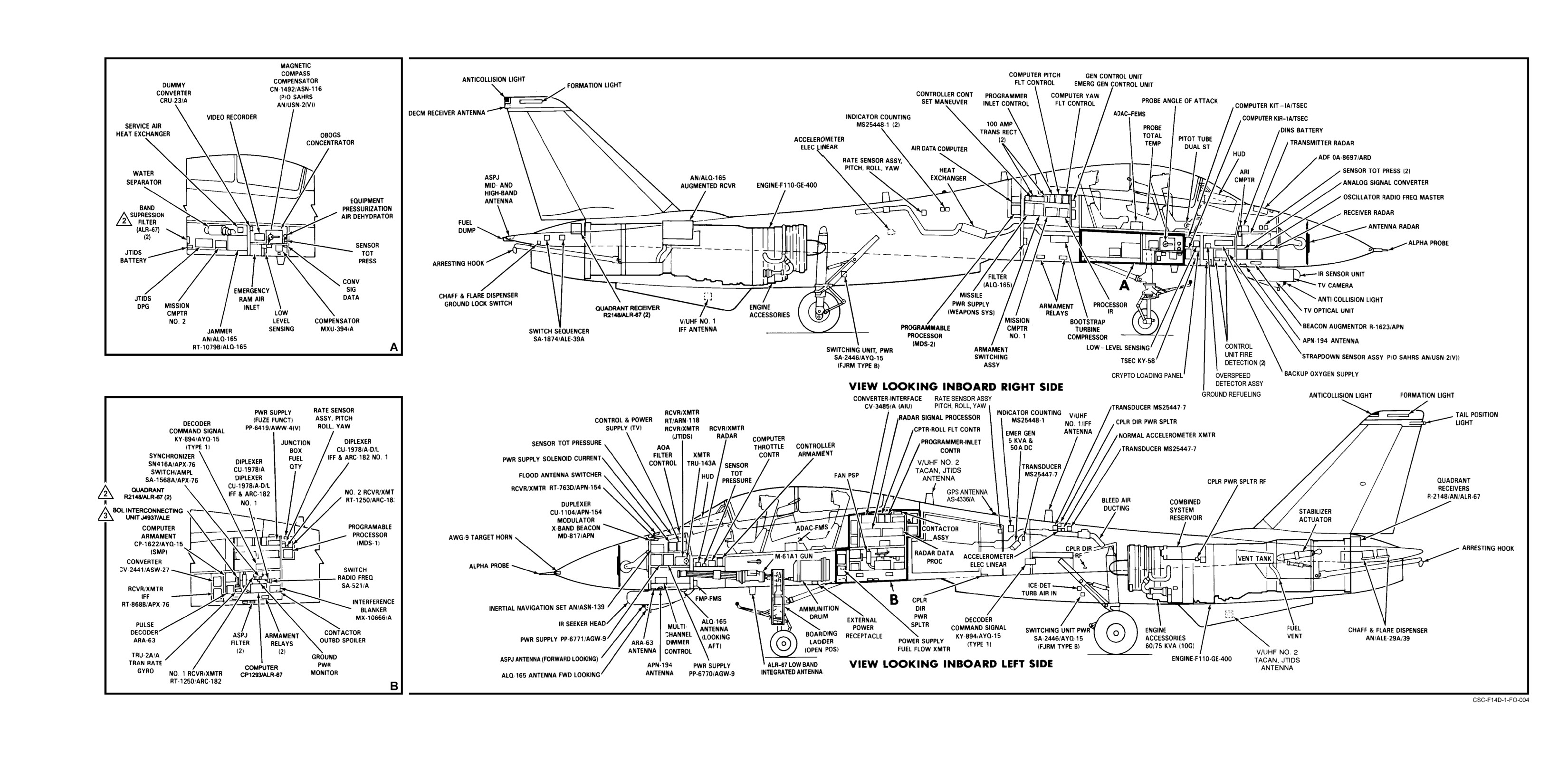
NAVAIR 01-F14AAD-1
General Arrangement (Sheet 1 of 2)
FO-1 (Reverse Blank)
ORIGINAL
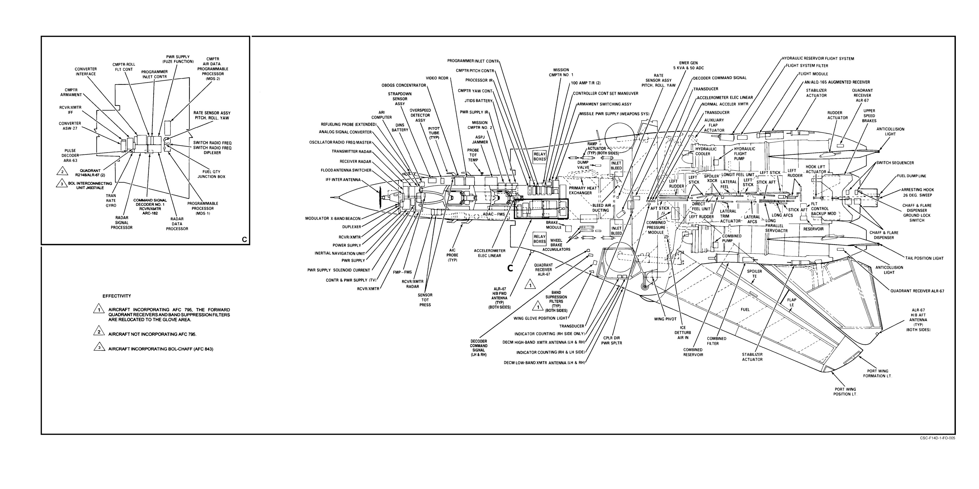
NAVAIR 01-F14AAD-1
General Arrangement (Sheet 2 of 2)
FO-2 (Reverse Blank)
ORIGINAL
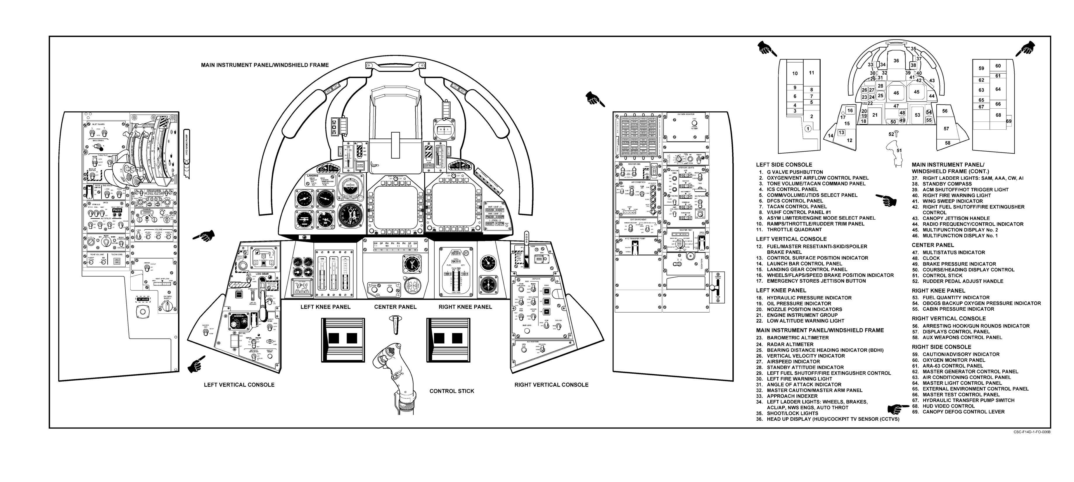
NAVAIR 01-F14AAD-1
Pilot Instrument Panels and Consoles
FO-3 (Reverse Blank)
CHANGE 1
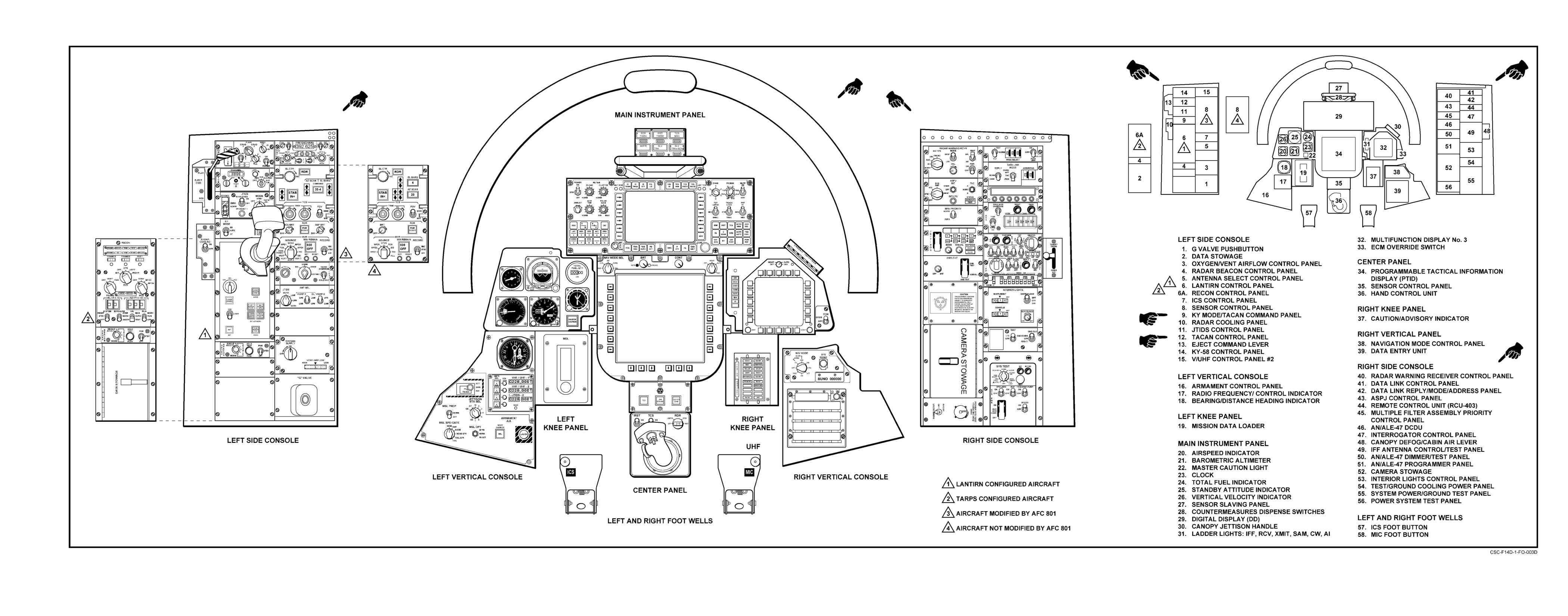
NAVAIR-01-F14AAD-1
RIO Instrument Panel and Console
FO-4 (Reverse Blank)
CHANGE 1
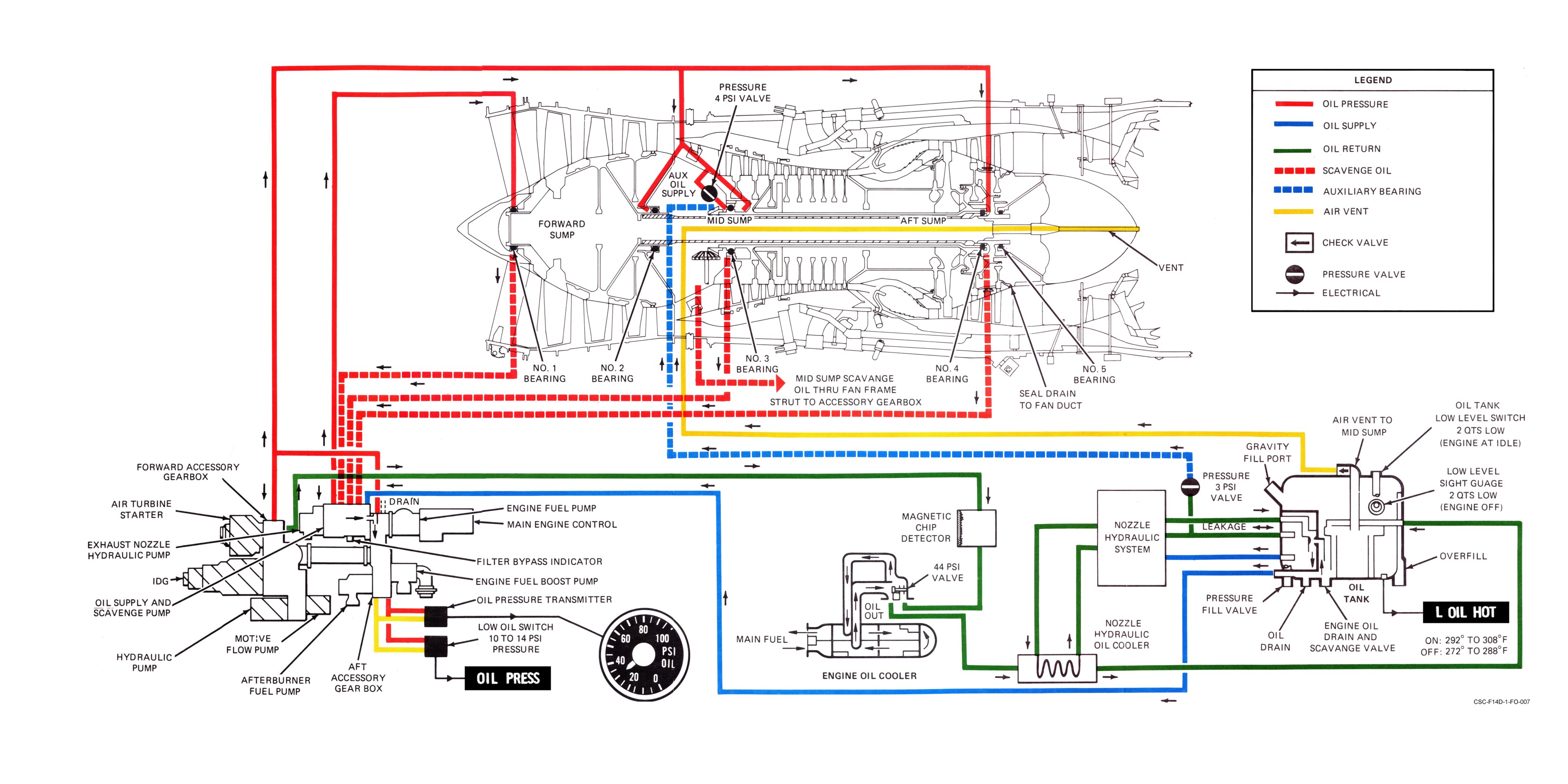
NAVAIR 01−F14AAD−1
Engine Oil System
FO−5 (Reverse Blank)
ORIGINAL
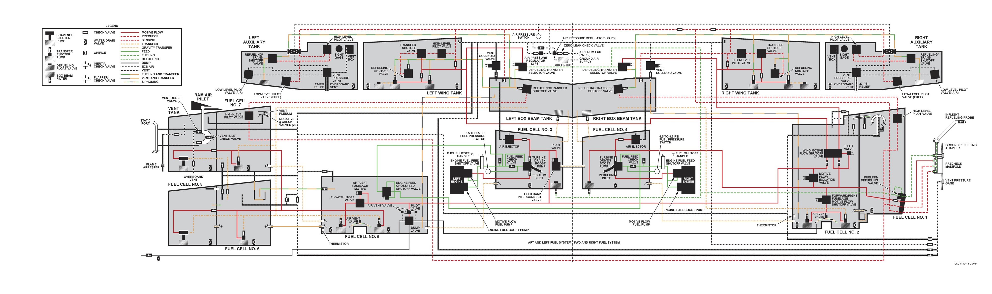
NAVAIR-01-F14AAD-1
Aircraft Fuel System
FO-6 (Reverse Blank)
ORIGINAL
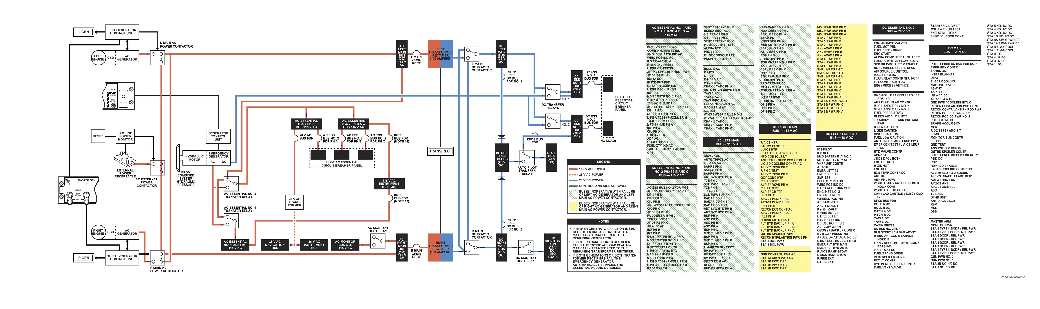
NAVAIR-01-F14AAD-1
Electrical Power System
FO-7 (Reverse Blank)
ORIGINAL
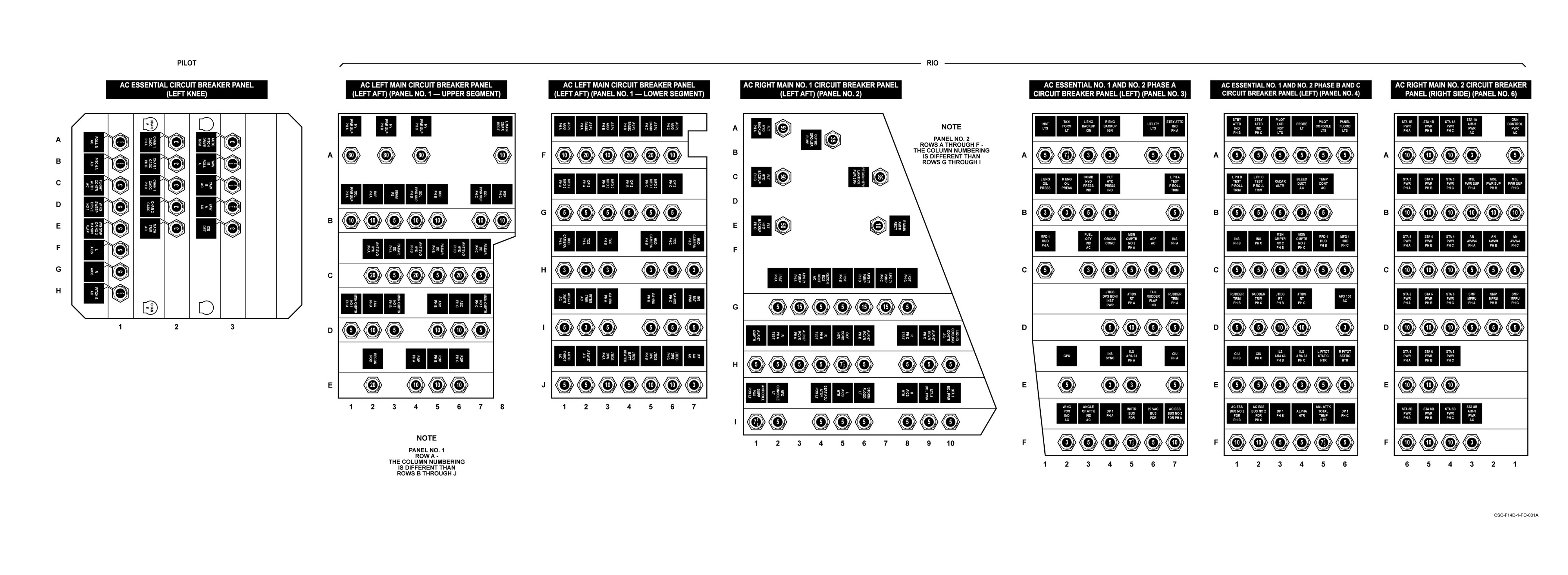
NAVAIR−01−F14AAD−1
AC Cockpit Circuit Breaker Panels
FO−8 (Reverse Blank)
ORIGINAL
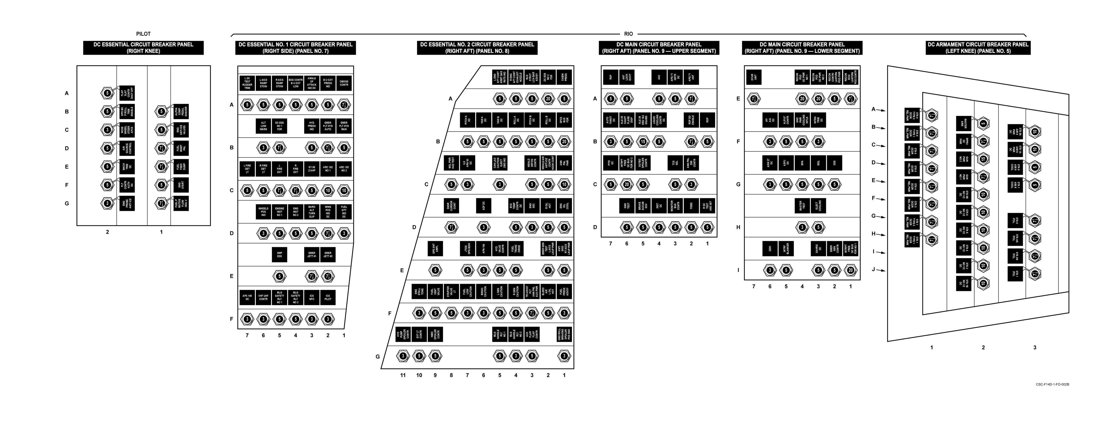
NAVAIR−01−F14AAD−1
DC Cockpit Circuit Breaker Panels
FO−9 (Reverse Blank)
ORIGINAL
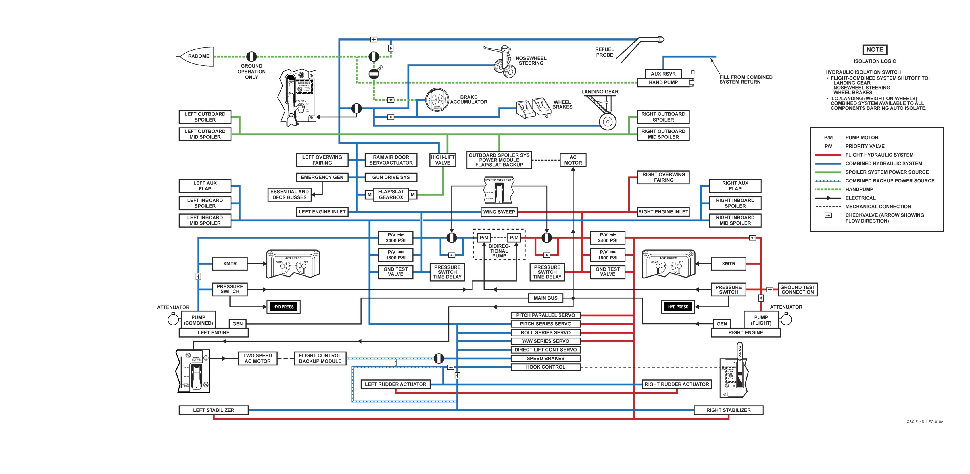
NAVAIR 01-F14AAD-1
Hydraulic System
FO-10 (Reverse Blank)
ORIGINAL
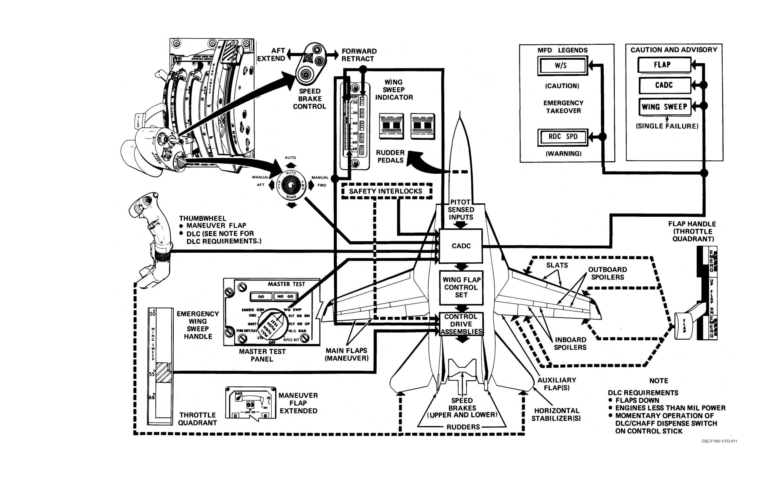
NAVAIR 01-F14AAD-1
Wing Sweep and Control Surfaces
FO-11 (Reverse Blank)
ORIGINAL
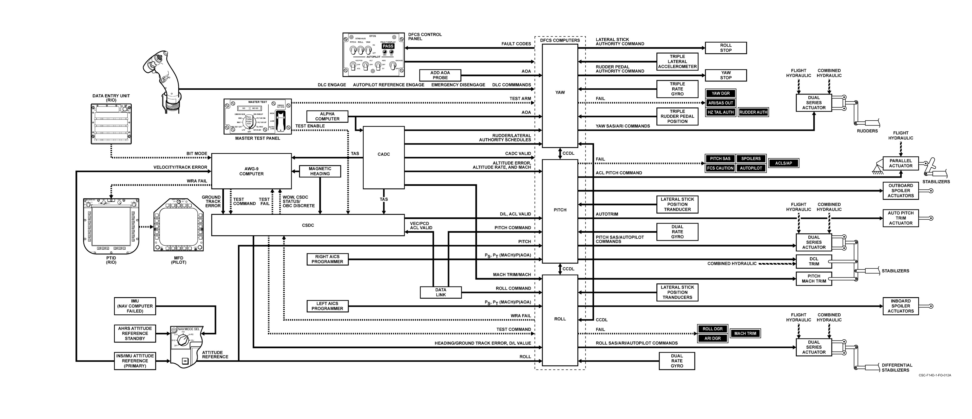
NAVAIR 01-F14AAD-1
Digital Flight Control System
FO-12 (Reverse Blank)
ORIGINAL
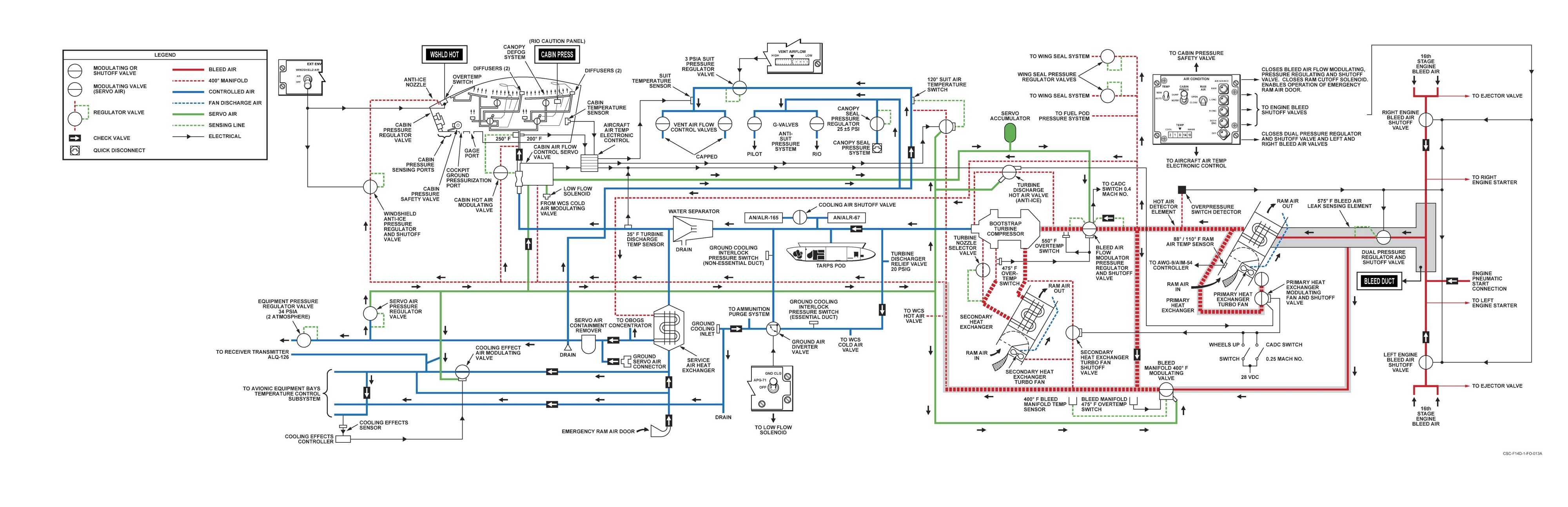
NAVAIR-01-F14AAD-1
Environmental Control System
FO-13 (Reverse Blank)
ORIGINAL
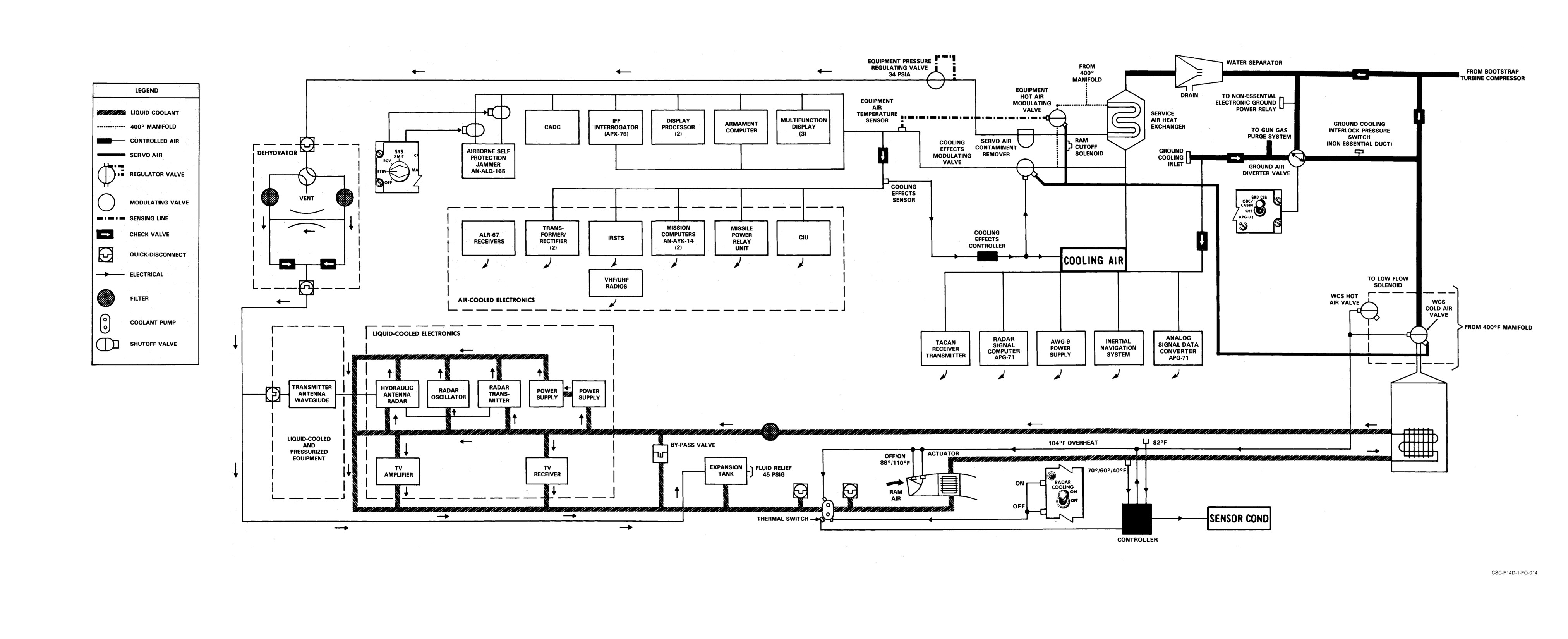
NAVAIR-01-F14AAD-1
Avionic Equipment Cooling
FO-14 (Reverse Blank)
ORIGINAL
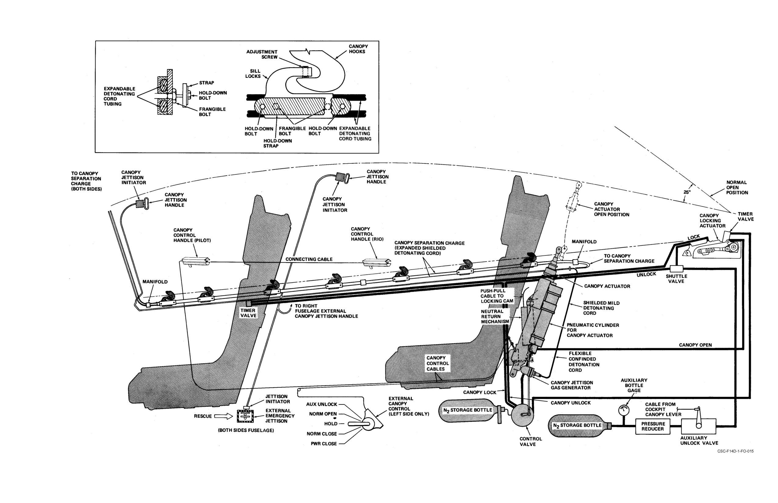
NAVAIR 01-F14AAD-1
Canopy Pneumatic and Pyrotechnic Systems
FO-15 (Reverse Blank)
ORIGINAL
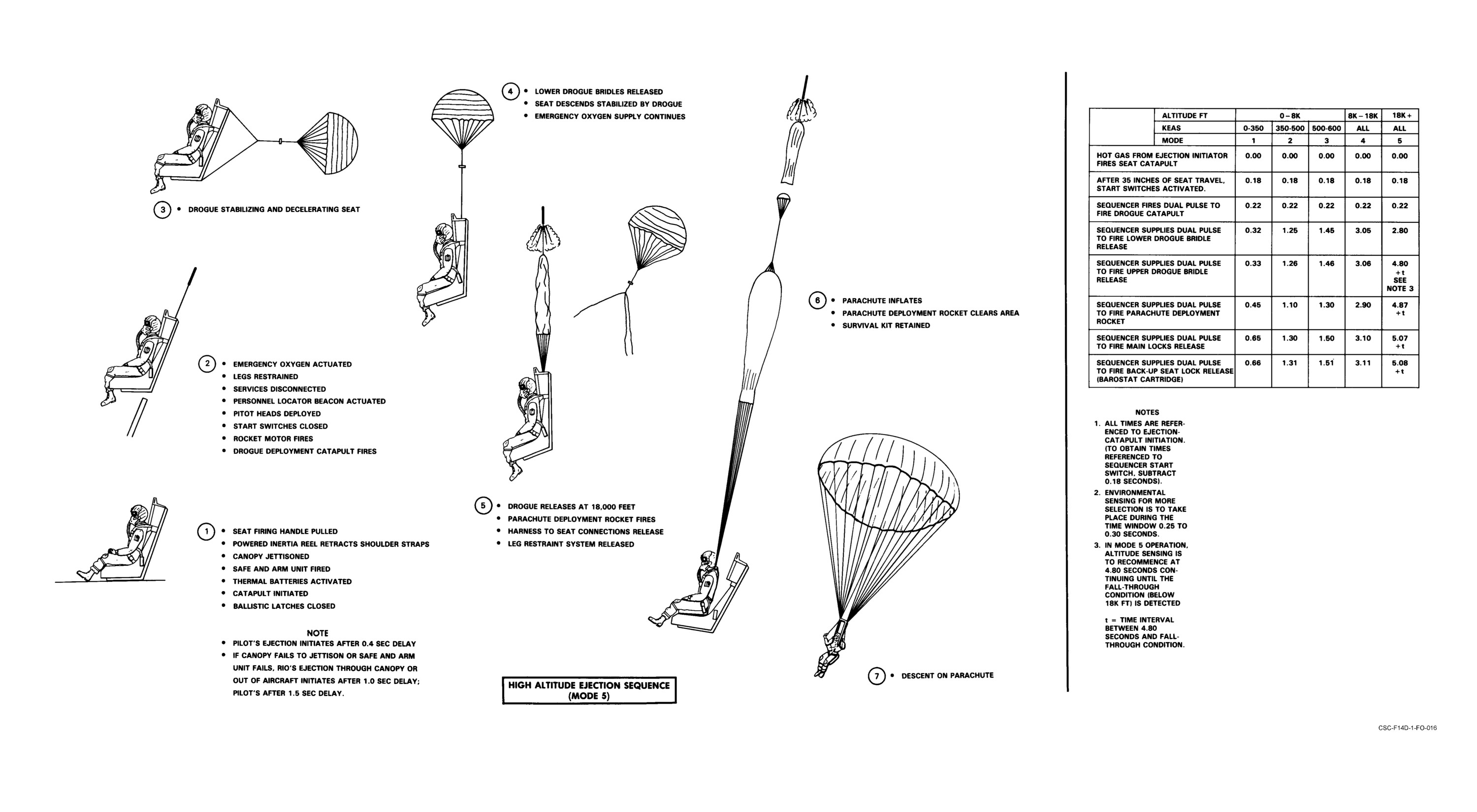
NAVAIR 01-F14AAD-1
Ejection Sequence (Sheet 1 of 2)
FO-16 (Reverse Blank)
ORIGINAL
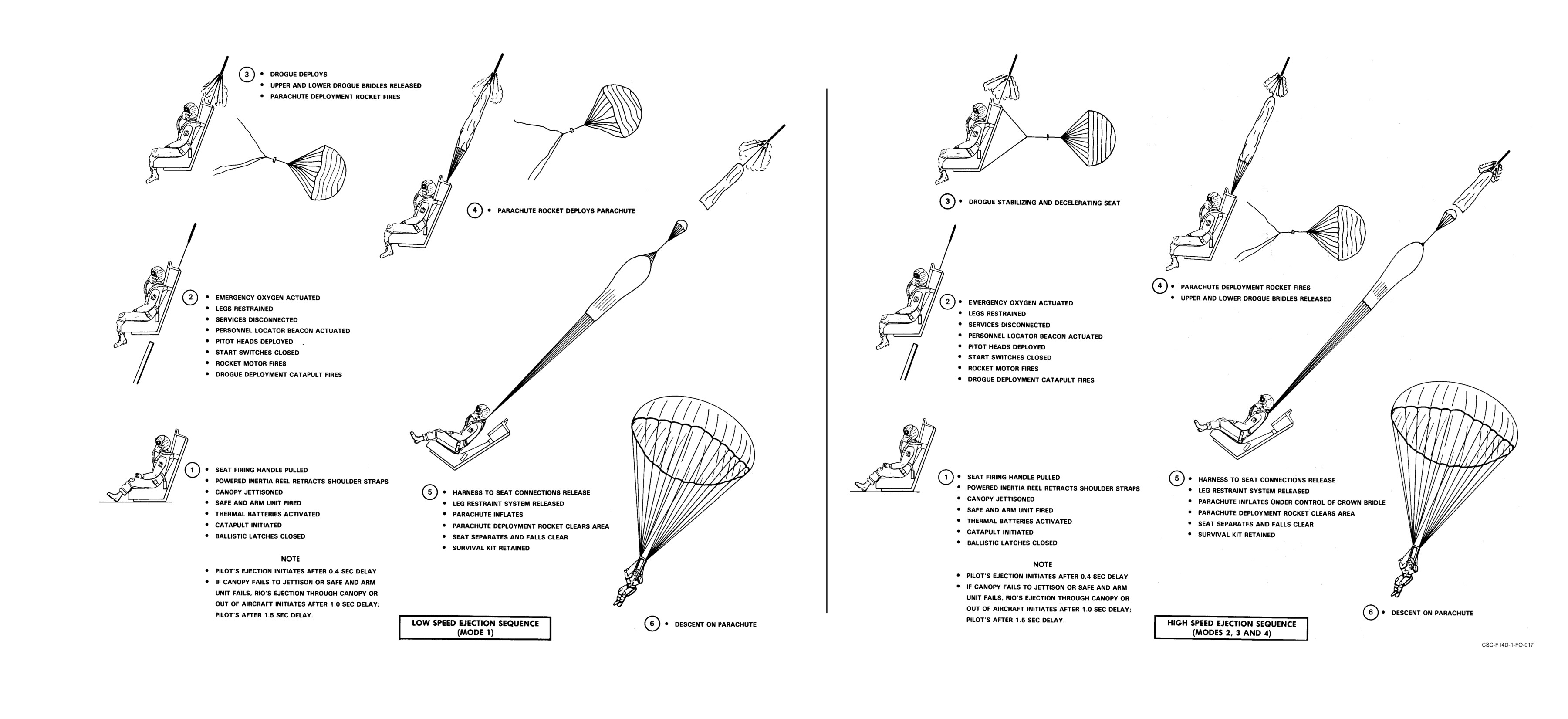
NAVAIR 01-F14AAD-1
Ejection Sequence (Sheet 2 of 2)
FO-17 (Reverse Blank)
ORIGINAL
NAVAIR 01-F14AAD-1
LIST OF EFFECTIVE PAGES
Effective Pages
Page Numbers
Effective Pages
Page Numbers
Change 2
1
(Reverse Blank)
Original
2-137 thru 2-139
Original
3
(Reverse Blank)
Change 1
2-140
Change 2
5
(Reverse Blank)
Change 2
2-141
Change 1
7
(Reverse Blank)
Original
2-142 thru 2-148
Original
9
(Reverse Blank)
Change 1
2-149
Original
11 thru 14
Original
2-150
Change 1
15
Change 1
2-151
Original
16 thru 22
Original
2-152 thru 2-164
Change 2
23
Change 1
2-165
Original
24 thru 27
Original
2-166, 2-167
Change 1
28, 29
Change 1
2-168
Original
30
Original
2-169 thru 2-221
Change 1
31, 32
Change 2
2-222
Original
33, 34
Original
2-223 thru 2-242
Change 1
35
Change 1
2-243
Original
36 thru 40
Original
2-244 thru 2-249
Original
41, 42
Change 1
2-250, 2-251
Change 1
43, 44
Original
2-252 thru 2-255
Original
45
Change 1
2-256, 2-256a (Reverse Blank)
Change 1
46, 47
Original
2-257 thru 2-262
Original
48 thru 50
Change 1
2-263
Original
51 thru 54
Original
2-264 thru 2-268
Original
55
(Reverse Blank)
Change 1
2-269
Original
1-1 thru 1-5 (Reverse Blank)
Change 2
2-270, 2-271
Original
2-1 thru 2-26
Original
2-272 thru 2-280
Change 1
2-27
Change 1
2-281, 2-282
Original
2-28 thru 2-45
Original
2-283 thru 2-284
Change 2
2-46
Original
3-1 thru 3-19 (Reverse Blank)
Original
2-47
Change 1
4-1
Change 2
2-48
Original
4-2 thru 4-19
Original
2-49 thru 2-51
Change 1
4-20
Change 1
2-52
Original
4-21 (Reverse Blank)
Original
2-53 thru 2-57
Original
57
(Reverse Blank)
Change 1
2-58
Original
5-1
Original
2-59 thru 2-60
Change 2
5-2
Change 2
2-61
Original
5-3 thru 5-5 (Reverse Blank)
Change 1
2-62
Original
59
(Reverse Blank)
Original
2-63
Original
6-1 thru 6-4
Change 1
2-64
Original
7-1 thru 7-16
Original
2-65 thru 2-77
Change 2
7-17
Change 1
2-78, 2-78a (Reverse Blank)
Original
7-18 thru 7-20
Original
2-79 thru 2-120
Change 1
7-21
Change 1
2-121 thru 2-124
Original
7-22
Original
2-125 thru 2-131
Change 2
7-23
Change 1
2-132
Change 1
7-24
Original
2-133
Original
7-25 thru 7-28
Change 1
2-134
Change 1
7-29
Original
2-135
Original
7-30
Change 1
2-136
Change 1
7-31
LEP-1
CHANGE 2
NAVAIR 01-F14AAD-1
Effective Pages
Page Numbers
Effective Pages
Page Numbers
Original
7-32 thru 7-38
Original
87
(Reverse Blank)
Original
8-1 thru 8-13 (Reverse Blank)
Original
19-1 thru 19-17
Original
9-1 thru 9-6
Change 1
19-18
Change 1
9-7 (Reverse Blank)
Original
19-19 thru 19-31 (Reverse Blank)
Original
10-1 thru 10-5
Original
20-1 thru 20-4
Change 2
10-6
Change 1
20-5
Original
10-7 thru 10-30
Original
20-6 thru 20-50
Change 1
10-31
Change 1
20-51 thru 20-52b (Reverse Blank)
Original
10-32
Original
20-53 thru 20-105 (Reverse Blank)
Original
61
(Reverse Blank)
Original
21-1 thru 21-8
Original
11-1 thru 11-8
Change 1
89
(Reverse Blank)
Change 2
11-9 thru 11-10a (Reverse Blank)
Original
22-1 thru 22-26
Original
11-11 thru 11-38
Original
23-1 thru 23-5 (Reverse Blank)
Original
63, 64
Original
91
(Reverse Blank)
Change 2
65
Original
37-1 thru 37-5 (Reverse Blank)
Original
66 thru 68
Original
38-1 thru 38-72
Change 2
69
Original
93
(Reverse Blank)
Original
70 thru 84
Original
39-1 thru 39-14
Change 2
12-1
Change 1
39-15
Original
12-2 thru 12-5 (Reverse Blank)
Original
39-16 thru 39-18
Original
13-1 thru 13-3 (Reverse Blank)
Original
95
(Reverse Blank)
Change 1
14-1
Original
40-1 thru 40-3
Original
14-2 thru 14-9
Change 1
40-4
Change 2
14-10, 14-11
Original
40-5, 40-6
Original
14-12 thru 14-16
Change 1
40-7, 40-8
Change 2
14-17 thru 14-20a (Reverse Blank)
Original
40-9 thru 40-12
Original
14-21 thru 14-30
Change 1
40-13
Change 1
14-31
Original
40-14 thru 40-19 (Reverse Blank)
Original
14-32 thru 14-41
Original
Index-1
Change 1
14-42, 14-43
Change 1
Index-2
Original
14-44 thru 14-48
Change 2
Index-3 thru Index-5
Change 2
14-49, 14-50
Original
Index-6 thru Index-10
Original
15-1 thru 15-8
Original
FO-1 (Reverse Blank)
Change 1
15-9, 15-10
Original
FO-2 (Reverse Blank)
Original
15-11, 15-12
Change 1
FO-3 (Reverse Blank)
Change 1
15-13
Change 1
FO-4 (Reverse Blank)
Original
15-14
Original
FO-5 (Reverse Blank)
Change 1
15-15
Original
FO-7 (Reverse Blank)
Original
15-16
Original
FO-8 (Reverse Blank)
Change 1
15-17
Original
FO-9 (Reverse Blank)
Original
15-18 thru 15-20
Original
FO-10 (Reverse Blank)
Change 1
15-21 (Reverse Blank)
Original
FO-11 (Reverse Blank)
Original
16-1 thru 16-4
Original
FO-12 (Reverse Blank)
Change 1
16-5, 16-6
Original
FO-13 (Reverse Blank)
Original
16-7 thru 16-9 (Reverse Blank)
Original
FO-14 (Reverse Blank)
Original
85
(Reverse Blank)
Original
FO-15 (Reverse Blank)
Original
17-1 thru 17-7
Original
FO-16 (Reverse Blank)
Change 2
17-8
Original
FO-17 (Reverse Blank)
Original
17-9 thru 17-14
Change 2
LEP-1, LEP-2
Original
18-1 thru 18-6
CHANGE 2
LEP-2
CIRCUIT BREAKERS
REFERENCE DATA
BINGO
ECS LEAKS
EMERGENCY PROCEDURE TABS
COCKPIT/OXYGEN
ECS
COOLANT/CANOPY
NAVAIR 01-F14AAP-1B
CONTROLLED
NATOPS
EJECT/
MANUAL
EGRESS
POCKET CHECKLIST
GROUND EGRESS
GENERATOR
TRANS/RECT
ELECTRICAL
F-14B
WOW
AIRCRAFT
AICS/AIRSTART
NOZZLE/START VALVE
ENGINE
OIL/THROTTLE
INFLIGHT
ON DECK
FIRE
ELECTRICAL
DISTRIBUTION STATEMENT C — DISTRIBUTION
AUTHORIZED TO U.S. GOVERNMENT AGENCIES
FLAPS
AND THEIR CONTRACTORS (1 JUNE 1992).
SPOILERS
FLIGHT
WINGSWEEP
CONTROL
SAS
DESTRUCTION NOTICE — FOR UNCLASSIFIED,
DUMP
LIMITED DOCUMENTS, DESTROY BY ANY
LEAK
METHOD THAT WILL PREVENT DISCLOSURE OF
FUEL
CONTENTS OR RECONSTRUCTION OF THE
PRESSURE
DOCUMENT.
TRANSFER
COMBINED
FLIGHT
HYDRAULICS
BRAKES
ISSUED BY AUTHORITY OF THE CHIEF OF
NAVAL OPERATIONS AND UNDER THE
DIRECTION OF THE COMMANDER,
ARRESTMENT
NAVAL AIR SYSTEMS COMMAND.
BRAKES
LANDING GEAR/
BLOWN TIRE
LANDING
LAUNCH BAR
TAKEOFF
01 AUGUST 2001
LANDING
SINGLE ENGINE
CRUISE/FUEL
OPS
MIGRATION
ABORT
TAKEOFF
BLOWN TIRE
NAVAIR 01-F14AAP-1B
MISCELLANEOUS DATA INDEX
ADMIN BRIEF
209
AIRSPEED INDICATOR FAILURE
252
ASYMMETRIC WINGSWEEP
LANDING AIRSPEED CHART
118
BINGO
189
CROSSWIND CHART
INSIDE BACK COVER
DFCS IN FLIGHT FAULT MATRIX CARDS
301
DFCS UP/DOWN STATUS CARDS
311
EMERGENCY FIELD ARRESTMENT GUIDE
168, 169
LANDING APPROACH AIRSPEED (14 UNITS) Ċ
SINGLE ENGINE
183
LANDING APPROACH AIRSPEED (15 UNITS)
255
LANDING DISTANCE GROUND ROLL Ċ
FLAPS DOWN
257, 258
FLAPS UP
259, 260
LANDING GEAR MALFUNCTION GUIDE
167
SAR ON SCENE COMMANDER CHECKLIST
313
TAKEOFF SPEED AND GROUND ROLL DISTANCE Ċ
MILITARY POWER Ċ FLAPS DOWN Ċ
CG = 6 PERCENT
250
MILITARY POWER Ċ FLAPS DOWN Ċ
CG = 16.2 PERCENT
251
MILITARY POWER Ċ FLAPS UP
249
Change 3