F-14D. FLIGHT MANUAL (2004) - page 14
NAVAIR 01−F14AAD−1
CONTINUOUS
SUBSYSTEM/DESIGNATION
INITIAL
COMMANDED
MONITOR
COCKPIT
ADAC CPć1770
30
20
2
N/A
DFCS AN/ASWć43
N/A
53
2
N/A
AICR Cć8684
N/A
63
2
N/A
AICL Cć8684
N/A
63
2
N/A
APC AN/ASWć105
N/A
83
2
83
ASPJ AN/ALQć165
N/A
110
30
110
BAG AN/APNć154
N/A
3
N/A
N/A
BSF
N/A
3
2
N/A
CADC CPć1035
N/A
4
2
N/A
CIU
2
2
10
N/A
DEU
N/A
20
2
N/A
DP1
N/A
40
5
N/A
DP2
N/A
40
5
N/A
DLS AN/ASWć27C
N/A
15
N/A
(Note 2)
EMSP1
N/A
N/A
2
N/A
EMSP2
N/A
N/A
2
N/A
GPS
30
4 Mins
N/A
N/A
IFB
N/A
3
2
N/A
IFI AN/APXć76
N/A
2
N/A
N/A
IFX AN/APXć100
N/A
2
2
N/A
INS AN/ASNć130
N/A
55 Mins
1
N/A
IRSTS
N/A
30
2
N/A
JTIDS AN/URCć107
10
15
12
N/A
MC1 AN/AYKć14
2
12
10
N/A
MC2 AN/AYKć14
2
12
10
N/A
MDL
N/A
(Note 3)
1
N/A
MFA LEFT
N/A
2
N/A
N/A
MFA RIGHT
N/A
2
N/A
N/A
RADAR AN/APGć71
210
150
2
N/A
RALT AN/APNć194
N/A
3
N/A
(Note 4)
RFP AN/ARCć182
N/A
N/A
2
N/A
RFR AN/ARCć182
N/A
N/A
2
N/A
RWR AN/ALRć67
N/A
N/A
1
(Note 5)
SAHRS AN/USNć2
16
5
5
N/A
SDIS
2
6
2
N/A
SMS AN/AYQć15
2
10
1
N/A
Figure 38Ć4.ĄSubsystem BIT Mode Test Times (Sheet 1 of 2)
ORIGINAL
38−6
NAVAIR 01−F14AAD−1
CONTINUOUS
SUBSYSTEM/DESIGNATION
INITIAL
COMMANDED
MONITOR
COCKPIT
TACAN AN/ARNć118 or AN/URCć107
(Note 6)
(Note 6)
(Note 6)
(Note 6)
TARPS
N/A
N/A
2
N/A
Notes:
1. All test times are in seconds unless otherwise noted.
2. This test is the Data Link PAD (D/L RAD) test initiated by the RIO or Pilot. This test remains in effect for as long as the
MASTER TEST panel switch is in D/L RAD. Refer to Operator Initiated BIT section for more information.
3. MDL Commanded BIT times of 5.0 and 65.0 seconds correspond to the Mission Data Loader (MDL) test, and the MDL
test including the Bulk Memory Checksum test, respectively.
4. This test remains in effect for as long as the PUSH TO TEST knob on the RADAR ALTITUDE indicator is held
depressed.
5. This test remains in effect for as long as the TEST switch on the RADAR WARNING RCVR panel is held to BlT. Once
released, the test completes in approximately 13 seconds.
6. JTIDS initial BIT will cause a 4−second loss of TACAN lock. A TACAN self−test is performed during JTIDS OBC. See
Chapter 20 for additional details.
Figure 38−4. Subsystem BIT Mode Test Times (Sheet 2 of 2)
Current failure information is also displayed on the
Continuous−monitor BIT is performed by each
PTID in the OBCCM window (refer to paragraph 38.5), and
subsystem on a continuous and noninterfering basis (i.e.,
on the MFDs in the warning/caution/advisory window for
subsystem continues to perform normal operational mode as
certain equipment failures.
well). The BIT time is usually 2 seconds. The MCS monitors
each subsystem at a 1−second rate in order to establish current
38.3.1
Built−in−Test Description
status (GO or NO GO).
Several types of BIT are supported by each subsystem
Commanded BIT is performed by each subsystem
and are performed internally. These modes include: power−
when commanded through the MFDs or by a cockpit control
up
(or initial), periodic
(continuous or automatic), and
panel (when available). This mode is typically the most
commanded (includes both MFD and cockpit control panel
comprehensive and provides the highest degree of fault
initiated) BIT. Refer to Figure 38−4 for approximate BIT
isolation. When used, this mode interrupts normal operation
times for each subsystem. Regardless of the BIT type,
of the selected subsystem. The MCS monitors the subsystem
detected failures are retained for the affected subsystem by
while it is in test and responds with GO or NO GO at the
the MCS. Each mode of BIT contains a series of tests that
completion of the test.
differ from mode to mode. Because of these differences, a
Data bus test is performed by the MCS in order to detect
priority for each subsystem determines when a subsystem
data bus (mission bus No. 1 and No. 2, and inter−computer
failure no longer exists. Other tests performed by the MCS
bus) channel failures. Computer bus channel failures are
include data−bus channel tests, and a test to determine the
detected and reported by the RDP to the MCS. Each channel
compatibility of each subsystem’s software load with the
is tested on MCS cold start, and when a subsystem first
MCS OFP.
responds on the data bus. The test consists of transmitting
several test patterns of data across each channel to a
38.3.1.1
BIT Modes
subsystem, and then reading back the data. A disagreement
The following is a brief description of each BIT mode.
in the data establishes a NO GO for the data bus channel at
Refer to Figure 38−4 for subsystem applicability.
fault. Since most bussed subsystems are dual redundant on
the data bus, a single−channel failure will not affect the
Initial BIT is performed by each subsystem upon the
operation of the applicable subsystem. In the event that both
application of electrical power. This mode of BIT is only
channel have failed, the subsystem will be maintained as
performed after power has been off for a specific length of
NOT READY, making the subsystem unavailable to the rest
time (i.e., cold start) and then restored. For shorter power
of the system.
interruptions
(i.e., warm start), this mode of BIT is not
performed. The MCS monitors each subsystem for a response
The isolation of DFCS faults to the WRA level requires
(GO or NO GO) at the completion of this mode.
reference to the fault codes displayed on the DCP (See
FigureĂ38−11).
38−7
ORIGINAL
NAVAIR 01−F14AAD−1
STATUS
DEFINITION
NOT READY
Subsystem is not responding on a data bus as determined by the MCS, due to one of the
following conditions: power−down, not installed, remote terminal failure, bus message
error excessively busy, or failure of all data bus channels to a particular subsystem. In
addition, any bus subsystem that does not complete commanded BIT within a specified
period of time will be set to this status type.
NO GO
Subsystem has at least one WRA fault detected as a result of performing one of its BIT
modes. These failures are reported to the MCS only after an appropriate failure threshold
has been reached. Depending on the extent of the failure, the subsystem may not be
operationally usable by the system, causing a degraded mode to be entered where
available. Subsystems that are not on a data bus and are not responding due to being
powered down or not installed are reported as NO GO.
CONFIG ERROR
Subsystem has an inconsistent software program, or firmware load as determined by the
MCS. This type of failure does not preclude the system from operationally using the
affected subsystem. The subsystem can be powered down at the flightcrew’s discretion to
prevent the subsystem from being used by the system.
Figure 38Ć5.ĄDefinition of BIT Status Types
are displayed on the OBC formats for every failed item.
These acronyms identify failures at the subsystem and WRA
level on various OBC formats. Equipment BIT status is
displayed as either NO GO, NOT READY, or CONFIG
ERROR. Refer to Figure 38−5 for status−type definitions.
Aircraft shall be considered down with PFCC, RFCC,
Note that absence of a failure acronym indicates that the
or YFCC codes in the DCP FAIL group or with an inoperative
equipment is GO. Refer to Figure 38−6 for a list of subsystems
DCP display. Initiation of OBC/IBIT with this condition will
versus types of status. Note that when the MCS cold−starts as
result in invalid IBIT indications.
a result of a power−transient or a system reset, BIT status for
equipment that is NOT READY will not be displayed as such
Note
for 1 minute. After this time has elapsed, only equipment that
is currently NOT READY will be considered failed. This
If a flight control computer fault is detected during
allows subsystems that need time to warmup or perform
DFCS IBIT, a PFCC, RFCC, or YFCC code will be logged
initial BIT to do so without being prematurely reported as
on the DCP. However, additional fault codes will be
NOĂGO.
suppressed, possibly masking other actual failures.
Each mode of subsystem BIT is weighted according to
Software compatibility test is performed by the MCS
the amount of fault isolation that it provides. Subsystem
in order to detect incompatible software program loads as
failures can be removed from the system (i.e., will clear any
compared to the configuration for the rest of the system. In
equipment failure maintained by the MCS) only by one of the
addition, a subsystem will test and report the internal
following:
compatibility between its main program load and firmware.
Each subsystem is tested by the MCS on MCS cold start and
1. Selecting system reset.
when a subsystem first responds on the data bus. When an
incompatibility is detected with a subsystem, the subsystem
2. Cycling power to the MCS.
status will be maintained as CONFIG ERROR, and a
computer message will be displayed indicating the WRA
3. Cycling power to subsystem (only pertains to equipĆ
fault.
ment on data bus). During power−off, equipment
BIT status reverts to NOT READY.
38.3.1.2
BIT Status/Priorities
4. CONFIG ERROR is overridden by NO GO or
OBC display formats provide the flightcrew with
NOT READY.
continuous status of avionics and radar subsystems. Note that
weapon and stores status are displayed on the SMS format,
5. Equipment status of NO GO will remain unless
which is selectable from the menu format. Failure acronyms
same or higher weight of BIT reports GO condition.
ORIGINAL
38−8
NAVAIR 01−F14AAD−1
38.3.1.3
MFD Commanded BIT
NOT
CONFIG
SUBSYSTEMS
READY
NO GO
ERROR
In addition to displaying equipment BIT status, the
ADAC
X
X
X
MFD OBC formats are the primary means for generating
command−initiated BIT. Testing can be controlled from any
AICL
X(1)
X
MFD on which an OBC format is displayed. The only other
AICR
X(1)
X
available method of testing (for equipment listed in Figure
APC
X(1)
X
38−4) is to use a dedicated cockpit panel to control test on an
ASPJ
X
X
X
individual equipment basis. Test controls allow tests of the
BAG
X(1)
X
selected subsystem(s) to be initiated or terminated. The OBC
display formats allow testing at several different levels,
BSF
X(1)
X
including sequence testing, functional group testing, and
CADC
X(1)
X
individual (or unit) testing. Sequence testing allows several
CIU
X
X
X
items to be tested at the same time, with the MCS
DEU
X
X
X
automatically testing (i.e., in parallel or in sequence) the
appropriate equipment. Functional group testing allows
DFCS
X(1)
X
functionally related equipment to be tested at the same time
DP1
X
X
X
in a similar manner to the sequence tests. Each OBC format
DP2
X
X
X
generally contains a series of pushbutton legends representĆ
DLS
X(1)
X
ing systems that have command−initiated BIT capability.
EMSP1
X
X
Commanded BIT can be initiated one at a time, or in any
combination, as long as the prerequisites for testing are
EMSP2
X
X
satisfied. Refer to paragraph 38.3.2 for commanded BIT test
GPS
X
X
prerequisites.
IFB
X(1)
X
OBC display formats also serve to provide feedback or
IFI
X
the progress of testing
(i.e., in test, test complete, and
IFX
X(1)
X
awaiting test) through MFD acronym status. Computer
INS
X
X
X
messages are generated and displayed on the MFDs in
IRSTS
X
X
X
response to invalid test selections.
JTIDS
X
X
38.3.1.4
Control Panel−Initiated BIT
MC1
X
X
X
MC2
X
X
X
Control panel/initiated BIT is an alternate mode of BIT
initiated from a cockpit control panel. Refer to Figure 38−4
MDL
X
X
for applicability. Control panel initiated BIT is described
MFA LEFT
X
with the applicable subsystem.
MFA RIGHT
X
RADAR
X
X
38.3.2
Test Prerequisites/Restrictions
RALT
X(1)
X
Commanded BIT testing requires that certain condiĆ
RFP
X
tions be satisfied prior to the test command from the MCS for
RFR
X
safety−of−flight purposes. These conditions govern the
RWR
X
X
X
control of all commanded BIT initiated through the MFDs
and depend on the type of test. In addition, there are some
SAHRS
X
X
X
restrictions that disable tests because of equipment or
SDIS
X
X
X
operational mode conflicts. (Initial and continuous BIT are
SMS
X
X
X
not subject to these conditions.)
TACAN
X
TARPS
X
38.3.2.1
BIT Interlocks/Test Restrictions
WOW
X
Preflight tests are enabled by the pilot selecting OBC
NOTE: (1) Subordinate to the converter interface unit
on the MASTER TEST panel with weight on wheels, TAS
(CIU), and equipment status is displayable as
<Ă76 knots, and handbrake set. These tests are designated
NO GO as a result of a subsystem not comĆ
preflight and it is recommended that they be performed at this
pleting commanded BIT within a set time.
time since a failure may constitute a flight safety hazard. All
interlocks are constantly checked for change in status to
Figure 38Ć6.ĄEquipment Subsystem BIT Status Types
ensure the safety of the aircraft. In−flight tests are performed
38−9
ORIGINAL
NAVAIR 01−F14AAD−1
only when the aircraft is airborne with weight off wheels and
sequence tests. Additional information for a subsystem
TAS > 76 knots. Refer to Figure 38−7.
failure can be found on the corresponding functional group
format. Each acronym that appears on the OBC basic format
38.3.3
Avionic BIT Operation
indicates that the subsystem is not currently operational.
Each acronym appears in a dedicated location as shown in
Avionic BIT operation is controlled through MFD
Figure 38−12.
OBC display formats. For some systems, dedicated control
panels serve as a redundant and alternate means for
38.3.3.1.2
Functional Group Formats/
controlling BIT. All OBC formats display equipment status,
Fail Data Format
equipment failure acronyms for detected WRA failures, and
the progress of testing. These formats provide the capability
The OBC functional group format display failures are
to manually initiate/terminate command BIT and to mask/
at the WRA level. Additional information for a WRA failure
unmask current failures on the displays. These formats are
can be found on the corresponding fail data format for that
accessible on any MFD including the pilot center (MFD1),
functional group. Subsystem failure status is indicated as
pilot right (MFD2), and RIO (MFD3) displays.
either NO GO, NOT READY, or CONFIG for each
subsystem in the functional group. Refer to Figure 38−5 for
When the system is powered up from a cold−start
failure status types. When the status is NOT READY for a
condition
(i.e., power to MCS off for greater than
300
subsystem on the bus, the WRA corresponding to the remote
milliseconds) or when system reset is ordered, the mission
terminal (i.e., the WRA that directly communicates on the
computers perform initial BIT. All other equipment takes
bus with the MCS) is displayed subordinate to the subsystem.
varying amounts of time to warm up or to complete initial
BIT. At the completion of mission computer initial BIT,
A prompt (* NEXT PAGE *) on the bottom of an OBC
MFD2 will display the OBC BASIC format. At all other
functional group format (or a fail data format) appears if there
times, the OBC BASIC format can be accessed on any MFD
are additional failure acronyms for the group or additional
by selecting the MENU1 pushbutton followed by the OBC
fail data pages. Pressing the PAGE pushbutton in response to
pushbutton. The OBC BASIC format allows initiation of
the prompt will cause the next page of information to be
various test sequences, and also serves as the menu for access
displayed. Paging past the last page will cause the first page
to all other OBC formats. Tests can also be commanded
to be displayed again.
through OBC functional group formats. OBC computer
Fail data information is only displayed on a fail data
messages provide feedback to the flightcrew and are
format after at least one commanded BIT has been performed
displayed when testing is completed or in response to test
for the applicable subsystem.
selections that are not acceptable because of invalid interĆ
locks and operational conflicts.
Note
When the system is in a backup mode of operation
(only one mission computer operational), it will support all
Fail data is available for display continuously for
the OBC functions that are normally provided in a full−up
CADC, EMSP1, and EMSP2.
mode (i.e., both mission computers operational).
Otherwise, if commanded bit has not been performed,
a prompt will be displayed on the first line of the fail data
38.3.3.1
MFD OBC Formats
format as FAIL DATA NOT AVAILABLE for the applicable
WRA or system.
There are several different types of OBC formats:
basic, functional group, fail data, maintenance, and failure
38.3.3.1.3
Failure Acronym Masking
history file. Figure 38−8 identifies the equipment that can be
commanded to test, or masked, from each of the format types.
Masking removes or inhibits display of OBC equipĆ
Figure 38−9 identifies all possible OBC failure acroĆ
ment failure acronyms for known WRA faults. Failure
nyms and failure history file acronyms that are displayed on
acronyms will be removed from the OBC formats (basic and
OBC formats. It also provides an explanation and possible
functional group) and from the PTID OBCCM window
action that the aircrew can take in response to the fault.
regardless of the mode of BIT that detected the failure.
Failure acronyms are maskable at the OBC basic level, where
38.3.3.1.1
OBC Basic
all currently failed equipment is affected, and also at the
The OBC basic format displays failures at the subĆ
system level and provides the capability to initiate the OBC
ORIGINAL
38−10
NAVAIR 01−F14AAD−1
FLIGHT STATUS
TEST SELECTS
EQUIPMENT TESTED
PREFLIGHT
Preflight test
(1) CIU, CADC, APC, DFCS, AICS,
RALT, IFB, ADAC, DSS, MDL, SMS,
Weight−on−wheels, TAS < 76 KTS,
(1) DLS, BSF, (2) SDIS, IRST, JTIDS
Master Test switch set to OBC.
Parking brake set
Retest test
(1) CIU, ADAC, DSS, MDL, DEU, SMS,
(3) ASPJ, (NON−RADIATE), SDIS, IRST
Individual/group test
(1) CIU, CADC, APC, DFCS, AICS
Weight−on−wheels, parking brake set
Individual/group test
(3) INS, SAHRS, JTIDS, MDL, GPS
Weight−on−wheels, TAS < 76 KTS
Individual/group test
RALT
Retest test
ADAC, DSS, MDL, DEU, SMS,
(2) ASPJ (NON−RADIATE), SDIS, IRST
INFLIGHT
Inflight test
IFB, DEU, IFX, BAG, SMS, (1) DLS,
(2) ASPJ (RADIATE), MFA LEFT/RIGHT
Weight−off−wheels, TAS> = 76 KTS
SDIS, IRST
Individual/group test
BAG, IFX, (3) ASPJ (RADIATE)
Retest test
ADAC, DSS, MDL, DEU, SMS, (2) ASPJ
(RADIATE), SDIS, IRST, GPS
Preflight/Inflight
Individual/group test
(4) DP1, (4) DP2, DEU, IFB, (5) MC1,
(5) MC2, ADAC, (6) MDL, SMS,
(1) DLS, SDIS, IRST, GPS
Retest test
ADAC, DSS, MDL, DEU, SMS, SDIS, IRST
NOTES:
(1) CIU/DLS:
When the CIU or DLS is selected for test through the MFDs, the system will reject the selection(s) if a CV
SINS mode of alignment is in progress. This allows the SINS alignment to continue to completion without
interruption.
(2) ASPJ:
In addition to the interlock conditions indicated above, the following switch settings must be made on the
ASPJ control panel in order to initiate test:
Ċ When the ASPJ is selected for test with the MFDs, the ASPJ will perform BIT and radiate
(i.e., transmit RF) only if XMIT switch is selected. If RCV is selected, the ASPJ will perform BIT without
radiating.
Ċ When the ASPJ Is selected for test with the MFDs, the ASPJ will not perform BIT if STBY or
OFF is selected.
Figure 38Ć7.ĄBIT Interlocks Test Restrictions (Sheet 1 of 2)
38−11
ORIGINAL
NAVAIR 01−F14AAD−1
(3) INS:
Prior to selecting INS for test with the OBC NAV format, TEST on the NAV MODE panel must be selected.
(4) DP1/DP2:
When DP1 or DP2 is selected for test through the OBC CD formats, the following restrictions apply:
ALLOWABLE TEST
SELECTION
FLIGHT STATUS
DP1 or DP2
In−flight (Weight off wheels), both DP’s must be operationally GO
OR
Preflight (Weight on wheels)
NONE
In−flight (Weight off Wheels), one DP not operationally GO
(5) MC1/MC2:
When MC1 or MC2 is selected for test with the OBC AUX formats, the following restrictions apply:
ALLOWABLE TEST
SELECTION
FLIGHT STATUS
MC1 or MC2
In−flight (Weight off wheels), both MCs must be operationally GO
OR
Preflight (Weight on wheels)
NONE
In−flight (Weight off wheels), one MC not operationally GO
(6) MDL:
Prior to selecting the MDL/DSS for test through the MFDs, the Mission Data Loader must be inserted into the
Mission Data Loader Receptacle (MDLR). MDL BIT will be limited (i.e., less bulk memory checksum test)
when the MDL is tested as part of a preflight or retest sequence. Otherwise, if the test selection is an
individual or functional group type made through the OBC AUX format, MDL BIT will include the performance
of the bulk memory checksum test. The bulk memory checksum test adds approximately 1 minute to the
overall test time.
Figure 38−7. BIT Interlocks Test Restrictions (Sheet 2 of 2)
ORIGINAL
38−12
NAVAIR 01−F14AAD−1
functional group/unit level, where only equipment in the
OBC DISPLAY
TEST SELECTION
FORMAT
TYPE
functional group is affected. Failure acronyms may also be
unmasked in order to cause their redisplay after having been
BASIC
SEQUENCES:
previously masked. Unmasking is initiated with OBC
Preflight
formats or by the system as a result of performing
commanded BIT. Whichever level of masking/unmasking is
Inflight
selected, all the corresponding equipment appearing on the
Retest
OBC basic, OBC functional group, and PTID OBCCM
Functional group
Group or individual:
window will be affected. Format examples are shown in
Figure 38−13. Note that the OBC maintenance formats are
FLT (flight)
DFCS, AICS, APC
unaffected by any masking operation. Masking and unmaskĆ
CNI (communication,
RFP, RFR, BAG, IFX,
ing is controlled via OBC basic, any OBC functional group,
navigation,
IFI, RALT, TCN
or any fail data format as follows:
identification)
1.
OBC basic masking is performed by selecting the
NAV (navigation)
CADC, CIU, DINS,
MSK function on the OBC basic format at which
SAHR
time the MSK pushbutton legend will be boxed.
CD (controls and
DEU, DP1, DP2
This allows all the equipment failure acronyms
displays)
currently appearing on the OBC basic format to be
AUX (auxiliary)
MC1, MC2, EMSP1,
removed. Unmasking is performed by pressing the
EMSP2, ADAC, MDL,
MSK pushbutton while it is boxed. As a result,
DBUS
failure acronyms are displayed for equipment
currently failed and the MSK pushbutton legend is
SMST (stores
SMS
unboxed to indicate that no failures are masked. The
management system)
MSK pushbutton appears boxed on the OBC BASIC
TAC (tactical)
DLC, JTIDS
format if there is at least one WRA failure masked
in the system.
EW (electronic warfare)
ASPJ, BSF, IFB,
RWR, MFA
2.
Functional group masking is performed by selecting
SNSR (sensors)
IRST RDR, SDIS,
the ALL and MSK pushbuttons on the respective
TARPS
OBC functional group format. The ALL pushbutton
FAIL DATA
legend is boxed to indicate its selection and unboxed
if deselected. Group masking is only performed if
CNI
the ALL pushbutton is boxed prior to making the
NAV
selection of the MSK pushbutton. Group masking
will only remove failure acronyms associated with
CD
equipment on the corresponding functional group
AUX
format. Group unmasking is performed by
deselecting the ALL/MSK pushbutton when the
JTIDS
MSK pushbutton legend is boxed. The MSK
SMST
pushbutton legend appears boxed if there is at least
SMST SWITCHES
one equipment that is masked on the corresponding
functional group format.
EW
SNSR
3.
Unit masking is performed by selecting equipment
and MSK pushbuttons. Any number of WRAs may
GPS
be selected prior to selecting the MSK pushbutton
MAINTENANCE
in order to mask more than one failure at the same
CURRENT FAILURES
time. Each equipment pushbutton legend is boxed to
indicate its selection and is unboxed if reselected.
FAILURE HISTORY FILE
Only those items that remain selected (i.e., boxed)
before selecting the MSK pushbutton will be
Figure 38Ć8.ĄOBC Display Format Types
masked. Unit unmasking is performed by selecting
the equipment and MSK pushbuttons when the
MSK pushbutton legend is boxed.
38−13
ORIGINAL
NAVAIR 01−F14AAD−1
FHF
OBC ACRONYM
ACRONYM
DEFINITION
REMARKS
ADAC
ADAC
Airborne Data Acquisition
ADAC failure, Fatigue and Engine MonitorĆ
Computer
ing data records will no longer be
recorded on the DSS
DFCS
DFCS
Digital Flight Control
Failure of a system WRA as shown below
System
ACCELEROMETER
AFCAM
PITCH ACTUATOR
AFCPA
PITCH COMPUTER
AFCPC
PITCH SENSOR
AFCPS
ROLL ACTUATOR
AFCRA
Aircrew should check the DCP folĆ
low
ing DFCS IBIT to determi
ne
ROLL COMPUTER
AFCRC
any flight control failures.
ROLL SENSOR
AFCRS
YAW ACTUATOR
AFCYA
YAW COMPUTER
AFCYC
YAW SENSOR
AFCYS
AICS
AICS
Air Inlet Control System
Failure of AICL or AICR (See below)
AICS−L or AICS−R
Air Inlet Control (Left or
Indicates which AICS has failed.
Right)
Used in conjunction with INLET/RAMPS
caution lights.
PROGRAMMER
AILP
Programmer failure, without INLET light,
AIRP
computer uses normal values
Operational mode, no flight restriction
Figure 38Ć9.ĄOBC Failure Acronyms (Sheet 1 of 11)
ORIGINAL
38−14
NAVAIR 01−F14AAD−1
FHF
OBC ACRONYM
ACRONYM
DEFINITION
REMARKS
NO. 1 RAMP
AILA1
NO. 1 actuator position does not agree with
ACTUATOR
AIRA1
command
NO. 2 RAMP
AILA2
NO. 2 actuator position does not agree with
ACTUATOR
AIRA2
command
NO. 3 RAMP
AILA3
NO. 3 actuator position does not agree with
ACTUATOR
AIRA3
command
STATIC PRESSURE
AILS1
Static pressure sensor With INLET light,
AIRS1
SENSOR fail safe mode. Without INLET
light, failure operational. No flight
restriction
TOTAL PRESSURE
AILS2
Total pressure sensor. With INLET light,
AIRS2
SENSOR fail safe mode
ANGLE OF ATTACK
AILS4
Angle−of−Attack (AOA) or engine fan
AIRS4
speed. (AFTC may be in secondary
mode.) Without INLET light, fail
operational. No flight restriction
ID/MCB
AILID
Identifier conflict
AIRID
APC
APC
Approach Power
Auto throttle inspection. System will default
Compensator
to BOOST automatically. A REV 4 AIC
programmer is installed in lieu of correct
REV 5 programmer.
ACCELEROMETER
APCAM
APC accelerometer fail
No associated light
Auto throttle inoperative
APC not authorized for landing
COMPUTER
APCPU
APC computer fail
Auto throttle inoperative
ASPJ
ASPJ
Airborne Self−Protection
ASPJ failure. ECM may not be available.
Jammer
Run commanded BIT
PROCESSOR
SPJPR
Possible processor failure. Run commandĆ
ed BIT to provide fault isolation
to WRA level
RECEIVER LOW
SPJRL
Low−band receiver failure
Figure 38−9. OBC Failure Acronyms (Sheet 2 of 11)
38−15
ORIGINAL
NAVAIR 01−F14AAD−1
FHF
OBC ACRONYM
ACRONYM
DEFINITION
REMARKS
RECEIVER HIGH
SPJRH
High−band receiver failure
RECEIVER AUG
SPJRA
Augmentation receiver failure
TRANSMITTER LOW
SPJTL
Low−band transmitter failure
TRANSMITTER HIGH
SPJTH
High−band transmitter failure
TRANSMITTER AUG
SPJTA
High−band augmentation transmitter failure
RWR INTERFACE
SPJRI
Interface failure between ASPJ and RWR
BAG
BAG
Beacon Augmentor
BAG not powered on
Run commanded BIT
Degraded position approach on automatic
carrier landing (ACL) and/or ground vectoring
BSF
BSF
Band Suppression Filters
BSF failure
FILTER 1ćRWR 315
BSF1
BSF filter FWD 315 deg
FILTER 2ćRWR 45
BSF2
BSF filter FWD 45 deg
FILTER 3ćASPJ
BSF3
BSF filter ćASPJ
CADC
CADC
Central Air Data Computer
Check caution/advisory lights. Examine
CADC Fail Data Format
CIU
CIU
Converter Interface Unit
CIU fail
DBUS
Data Bus
MIL−STD−1553 data bus channel failure
(See below)
ADAC MBUS 2
AAC2A
Mission Bus NO. 2 channel A fail
CHAN A
ADAC MBUS 2
AAC2B
Mission Bus NO. 2 channel B fail
CHAN B
ARDP MBUS 1
RDP1A
Mission Bus NO. 1 channel A fail
CHAN A
Figure 38−9. OBC Failure Acronyms (Sheet 3 of 11)
ORIGINAL
38−16
NAVAIR 01−F14AAD−1
FHF
OBC ACRONYM
ACRONYM
DEFINITION
REMARKS
ARDP MBUS 1
RDP1B
Mission Bus NO. 1 channel B fail
CHAN B
ARDP MBUS 2
RDP2A
Mission Bus NO. 2 channel A fail
CHAN A
ARDP MBUS 2
RDP2B
Mission Bus NO. 2 channel B fail
CHAN B
RM1C
Computer Bus (Radar/MC1) channel fail
RM2C
Computer Bus (Radar/MC2) channel fail
RCIUC
Computer Bus (Radar/CIU) channel fail
ASPJ MBUS 1
SPJ1A
Mission Bus NO. 1 channel A fail
CHAN A
ASPJ MBUS 1
SPJ1B
Mission Bus NO. 1 channel B fall
CHAN B
CIU MBUS 2 CHAN A
CIU2A
Mission Bus NO. 2 channel A fail
CIU MBUS 2 CHAN B
CIU2B
Mission Bus NO. 2 channel B fail
DSS MBUS 2 CHAN A
DSS2A
Mission Bus NO. 2 channel A fail
DSS MBUS 2 CHAN B
DSS2B
Mission Bus NO. 2 channel B fail
DP1 MBUS 1 CHAN A
DP11A
Mission Bus NO. 1 channel A fail
DP1 MBUS 1 CHAN B
DP11B
Mission Bus NO. 1 channel B fail
DP2 MBUS 2 CHAN A
DP22A
Mission Bus NO. 2 channel A fail
DP2 MBUS 2 CHAN B
DP22B
Mission Bus NO. 2 channel B fail
DEKI MBUS 2 CHAN A
DEU2A
Mission Bus NO. 2 channel A fail
DEKI MBUS 2 CHAN B
DEU2B
Mission Bus NO. 2 channel B fail
INS MBUS 2 CHAN A
INS2A
Mission Bus NO. 2 channel A fail
MDL MBUS 2 CHAN A
MDL2A
Mission Bus NO. 2 channel A fail
MDL MBUS 2 CHAN B
MDL2B
Mission Bus NO. 2 channel B fail
Figure 38−9. OBC Failure Acronyms (Sheet 4 of 11)
38−17
ORIGINAL
NAVAIR 01−F14AAD−1
FHF
OBC ACRONYM
ACRONYM
DEFINITION
REMARKS
INS MBUS 2 CHAN B
INS2B
Mission Bus NO. 2 channel B fail
IRST MBUS 1 CHAN A
IR1A
Mission Bus NO. 1 channel A fail
IRST MBUS 1 CHAN B
IR1B
Mission Bus NO. 1 channel B fail
JTIDS MBUS 2 CHAN A
JT2A
JTIDS MBUS 2 CHAN B
JT2B
MC1 MBUS 2 CHAN A
MC12A
Mission Bus NO. 2 channel A fail
MC1 MBUS 2 CHAN B
MC12B
Mission Bus NO. 2 channel B fail
MC2 MBUS 2 CHAN A
MC22A
Mission Bus NO. 2 channel A fail
MC2 MBUS 2 CHAN B
MC22B
Mission Bus NO. 2 channel B fail
MC1 MBUS 1 CHAN A
MC11A
Mission Bus NO. 1 channel A fail
MC1 MBUS 1 CHAN B
MC11B
Mission Bus NO. 1 channel B fail
MC2 MBUS 1 CHAN A
MC2IA
Mission Bus NO. 1 channel A fail
MC2 MBUS 1 CHAN B
MC2IB
Mission Bus NO. 1 channel B fail
MC2 IBUS CHAN A
MC21A
Intercomputer Bus NO. 1 channel A fail
MC2 IBUS CHAN B
MC21B
Intercomputer Bus NO. 1 channel B fail
SAHRS MBUS 1 CHAN A
SHR1A
Mission Bus NO. 1 channel A fail
SAHRS MBUS 1 CHAN B
SHR1B
Mission Bus NO. 1 channel B fail
SDIS MBUS 1 CHAN A
SDI1A
Mission Bus NO. 1 channel A fail
SDIS MBUS 1 CHAN B
SDI1B
Mission Bus NO. 1 channel B fail
SMP MBUS 2 CHAN A
SMP2A
Mission Bus NO. 2 channel A fail
SMP MBUS 2 CHAN B
SMP2B
Mission Bus NO. 2 channel B fail
DEU
DEU
Data Entry Unit
DEU failure
Figure 38−9. OBC Failure Acronyms (Sheet 5 of 11)
ORIGINAL
38−18
NAVAIR 01−F14AAD−1
FHF
OBC ACRONYM
ACRONYM
DEFINITION
REMARKS
DINS
DINS
Digital Inertial Navigation
INS or battery failure
System
INERTIAL NAV SYSTEM
INS
INS failure
GPS
GPS
Global Positioning
GPS failure
System
INS BATTERY BACK−UP
DNSPS
INS battery failure
DLS
DLS
Data Link System
Data Link powered off.
Run commanded BIT
JTIDS
JTIDS
Joint Tactical Information
JTIDS failure
Distribution System
SDU
JTSDU
Secure Data Unit
SDU (KGV−8) failure/JTIDS crypto keys
are not loaded.
BATTERY
JTBAT
JTIDS Battery
JTIDS Battery Failure. Keys will not
load/hold in STBY with a failed battery.
RCVR/XMTR
JTRT
JTIDS
JTIDS R/T failure. This can also affect
Receiver/Transmitter
TACAN operation.
DATA PROCESSOR
JTDDP
JTIDS Digital Data
JTIDS DDP failure. This unit is part
Processor
of the JTIDS Data Processor Group.
INTERFACE UNIT
JTIU
JTIDS Interface Unit
JTIDS IU failure. This unit is part of
the JTIDS Data Processor Group.
DSS
DSS
Data Storage Set
DSS failure. Possible loss of data on
data storage unit.
EMSP1
EMSP1
Engine Monitoring Signal
EMSP1 failure
Processor no. 1
EMSP2
EMSP2
Engine Monitoring Signal
EMSP2 failure
Processor no. 2
IFB
IFB
Interference Blanker
Possible interference between TACAN,
Radar Altimeter, IFF, APG−71, RWR,
and ASPJ
IRST
IRST
Infrared Search and Track
IRST failure
SENSOR UNIT
IRSU
Sensor unit failure
ELECTRONIC UNIT
IREU
Electronic unit failure
IFI
IFI
IFF Interrogator
APX−76 failure
RECEIVER/ TRANSMITTER
IFIRT
Receiver/transmitter failure
SWITCH/AMP
IFISW
Switch amplifier failure
KIR COMPUTER
IFN
APX−76 computer failure/not installed
SYNCHRONIZER
IFISYS
Synchronizer failure
Figure 38−9. OBC Failure Acronyms (Sheet 6 of 11)
38−19
ORIGINAL
NAVAIR 01−F14AAD−1
FHF
OBC ACRONYM
ACRONYM
DEFINITION
REMARKS
IFX
IX
IFF Transponder
APX−100 failure
TRANSPONDER
IFXPN
IFF failure. Set MASTER switch on IFF
control panel to NORM. Select test for
each mode and observe light.
COMPUTER
IFA
APX−100 computer failure
MC1
MC1
Mission Computer NO. 1
MC1 failure. System will revert to backup
mode if MC2 is functional.
MC2
MC2
Mission Computer NO. 2
M2 failure. System will revert to backup
mode if MC1 is functional.
MDS1
Multifunction Display
MDS1 failure
System NO. 1
DISPLAY PROCĆ
DP1
DP NO. 1 failure
ESSOR
PILOT CENTER ć
MFD1
Pilot center MFD failure
MFD 1
HUD
HUD
Head−up display failure
PILOT RIGHTć
MFD2
Pilot right MFD failure
MFD 2
RIO ć MFD 3
MFD3
RIO MFD failure
HUD INTERFACE
HUDI
Interface failure between DP NO. 1
and HUD, or HUD not powered up
MFD 1 INTERFACE
MFD1I
Interface failure between DP NO. 1 and
MFD NO. 1, or MFD NO. 1 not powered up
MFD 2 INTERFACE
MFD2I
Interface failure between DP NO. 1 and
MFD NO. 2, or MFD NO. 2 not powered up
MFD 3 INTERFACE
MFD3I
Interface failure between DP NO. 1 and
MFD NO. 3, or MFD NO. 3 not powered up
MDS2
Multifunction Display
MDS2 failure
System NO. 2
DISPLAY
DP2
DP NO. 2 failure. System will revert to DP.
PROCESSOR
backup mode if DP NO. 1 is functional.
Figure 38−9. OBC Failure Acronyms (Sheet 7 of 11)
ORIGINAL
38−20
NAVAIR 01−F14AAD−1
FHF
OBC ACRONYM
ACRONYM
DEFINITION
REMARKS
PILOT CENTER ć
MFD1
Pilot center MFD failure
MFD 1
HUD
HUD
Head−up display failure
PILOT RIGHTć
MFD2
Pilot right MFD failure
MFDĂ2
RIO ć MFD 3
MFD3
RIO MFD failure
HUD INTERFACE
HUDI
Interface failure between DP NO. 2 and
HUD, or HUD not powered up
MFD 1 INTERFACE
MFD1I
Interface failure between DP NO. 2 and
MFD NO. 1, or MFD NO. 1 not powered up
MFD 2 INTERFACE
MFD2I
Interface failure between DP NO. 2 and
MFD NO. 2, or MFD NO. 2 not powered up
MFD 3 INTERFACE
MFD3I
Interface failure between DP NO. 2 and
MFD NO. 3, or MFD NO. 3 not powered up
DP1/DP2
DP12I
Interface failure between DP NO. 1 and DP
INTERFACE
NO. 2
MFAL
Multiple Filter Assembly
MFA left failure
Left
FILTER A
MFALA
Filter A failure
FILTER B
MFALB
Filter B failure
FILTER C
MFALC
Filter C failure
MFAR
Multiple Filter Assembly
MFA right failure
Right
FILTER A
MFARA
Filter A failure
FILTER B
MFARB
Filter B failure
FILTER C
MFARC
Filter C failure
RDR
Radar
APG−71 failure
RADAR
Radar not powered/not installed
Figure 38−9. OBC Failure Acronyms (Sheet 8 of 11)
38−21
ORIGINAL
NAVAIR 01−F14AAD−1
FHF
OBC ACRONYM
ACRONYM
DEFINITION
REMARKS
ARDP
Advanced Radar Data
ARDP failure
Processor
ARSP
Advanced Radar Signal
ARSP failure
Processor
BPS
Beam Power Supply
BPS failure
RCVR
Receiver
RCVR failure
DD
Digital Display
DD failure
RDHCU
Sensor Hand Control
SHC failure
XMTR
Transmitter
XMTR failure
CPS
Collector Power Supply
CPS failure
SPS
Solenoid Power Supply
SPS failure
ANT
Antenna Array
ANT failure
RIC
Radome Interlock
RIC failure
ASC
Advanced Signal
ASC failure
Converter
RDSCU
Radar Sensor Control Unit
RDSCU failure
PTID
Programmable Tactical
PTID failure
Information Display
TCS
Television Camera
TCS failure
System
RALT
RALT
Radar Altimeter
RALT failure (OBC BASIC)
RADAR ALT
RALT
Radar Altimeter
RALT failure (OBC CNI)
RFP
RFP
Radio Frequency Pilot
Pilot RFI failure
RFR
RFR
Radio Frequency RIO
RIO RFCI failure
SAHRS
SAHRS
Standard Attitude Heading
SAHRS failure. Loss of back−up
Reference Set
navigation mode
Figure 38−9. OBC Failure Acronyms (Sheet 9 of 11)
ORIGINAL
38−22
NAVAIR 01−F14AAD−1
FHF
OBC ACRONYM
ACRONYM
DEFINITION
REMARKS
SDIS
SDIS
Sensor Display
SDIS failure
Indicator Set
SENSOR CONTROL
SDSCU
Sensor control unit failure
UNIT
SENSOR SLAVING
SDSSP
Sensor slaving panel failure
PANEL
SMS
Stores Management Set
SMS failure
SMP
SMP
Stores management processor failure
MPRU
MPRU
Missile power relay unit failure
GUN CONT UNIT
GCU
Gun control unit failure
FTJU STA 2
FTJ2
Fuel tank jettison unit station No. 2 failure
FTJU STA 7
FTJ7
Fuel tank jettison unit station No. 7 failure
TYPE 1 DECODER
D1S1
Type 1 decoder station 1A/B failure
1A/B
TYPE 1 DECODER 3/6
D1S36
Type 1 decoder station 3/6 failure
TYPE 1 DECODER 4/5
D1S45
Type 1 decoder station 4/5 failure
TYPE 1 DECODER
D1S8
Type 1 decoder station 8A/B failure
8A/B
TYPE 2 DECODER 1B
D2S1B
Type 2 decoder station 1B failure
TYPE 2 DECODER 3
D2S3
Type 2 decoder station 3 failure
TYPE 2 DECODER 4
D2S4
Type 2 decoder station 4 failure
TYPE 2 DECODER 5
D2S5
Type 2 decoder station 5 failure
TYPE 2 DECODER 6
D2S6
Type 2 decoder station 6 failure
TYPE 2 DECODER 8B
D2S8B
Type 2 decoder station 8B failure
AWW−4
AWW−4
AWW−4 electrical fuzing switch failure
MISSILE PS
MPS
AIM−54 missile power supply failure
Figure 38−9. OBC Failure Acronyms (Sheet 10 of 11)
38−23
ORIGINAL
NAVAIR 01−F14AAD−1
FHF
OBC ACRONYM
ACRONYM
DEFINITION
REMARKS
TCN
TACAN
Tactical Air Navigation
TACAN failure (OBC BASIC)
TACAN
TACAN
Tactical Air Navigation
TACAN failure (OBC CNI)
TARP1
TARP1
Tactical Airborne
TARP system failure (crew alert)
Reconnaissance Pod
TARP2
TARP2
Tactical Airborne
TARP/CIU communication failure
Reconnaissance Pod
RWR
RWR
Radar Warning Receiver
RWR failure
COMPUTER
RWRCP
Analyzer (CP−1293) failure
CONTROL STATUS
RWRCU
Control status unit failure
UNIT
QUAD RECEIVER 45
RWRQ1
Quadrant receiver (45 degrees) failure
QUAD
RWRQ2
Quadrant receiver (135 degrees) failure
RECEIVERĂ135
QUAD
RWRQ3
Quadrant receiver (225 degrees) failure
RECEIVERĂ225
QUAD
RWRQ4
Quadrant receiver (315 degrees) failure
RECEIVERĂ315
SPECIAL RCVR
RWRSR
Superhet receiver failure
INTEGRATED
RWRAN
Integrated antenna failure
ANTENNA
ASPJ INTERFACE
RWRAI
Interface failure between RWR and ASPJ
IFB INTERFACE
RWRBI
Interface failure between RWR and IFB
WOW
WOW
Weight on/off wheel discrete failure
Figure 38−9. OBC Failure Acronyms (Sheet 11 of 11)
ORIGINAL
38−24
NAVAIR 01−F14AAD−1
FAILED COMPONENT
LIGHT
OBC ACRONYM
Pitch Rate Gyro (1)
FCS CAUTION
Pitch Sensor
Pitch Rate Gyro (2)
FCS CAUTION
Pitch Sensor
PITCH SAS
Roll Rate Gyro (1)
FCS CAUTION
Roll Sensor
Roll Rate Gyro (2)
FCS CAUTION
Roll Sensor
ROLL DGR
ARI DGR
ARI/SAS OUT
Yaw Rate Gyro (1)
FCS CAUTION
Yaw Sensor
Yaw Rate Gyro (2, 3)
FCS CAUTION
Yaw Sensor
ARI DGR
YAW DGR
ARI / SAS OUT
Lateral Accel (1)
FCS CAUTION
Accelerometer
Lateral Accel (2, 3)
FCS CAUTION
Accelerometer
ARI DGR
YAW DGR
ARI / SAS OUT
Pitch Series Actuator (1, 2)
PITCH SAS
Pitch Actuator
Roll Series Actuator (1)
ROLL DGR
Roll Actuator
ARI DGR
Roll Series Actuator (2)
ROLL DGR
Roll Actuator
ARI DGR
ARI / SAS OUT
Yaw Series Actuator (1)
ARI DGR
Yaw Actuator
YAW DGR
Yaw Series Actuator (2)
ARI DGR
Yaw Actuator
YAW DGR
ARI / SAS OUT
Spoilers (Any Inboard)
SPOILER
Roll Actuator
Spoilers (Any Outboard)
SPOILER
Pitch Actuator
Pitch Parallel Actuator
ACLS / AP
Pitch Actuator
AUTOPILOT
DLC Trim Actuator
Ċ
PITCH ACTUATOR
Pitch Autotrim Actuator
AUTOPILOT
PITCH ACTUATOR
Mach Trim Actuator
MACH TRIM
Ċ
Lateral Authority Actuator
HZ TAIL AUTH
Ċ
Rudder Authority Actuator
RUDDER AUTH
Ċ
Figure 38Ć10.ĄDFCS Caution Lights and Acronyms (Sheet 1 of 2)
38−25
ORIGINAL
NAVAIR 01−F14AAD−1
FAILED COMPONENT
LIGHT
OBC ACRONYM
Pitch Feel Switches
ACLS / AP
Ċ
AUTOPILOT
Right AICS Static Pressure
FCS CAUTION
Pitch Sensor
ARI DGR
Left AICS Static Pressure
FCS CAUTION
Pitch Sensor
ARI DGR
Right AICS Total Pressure
FCS CAUTION
Pitch Sensor
ARI DGR
Left AICS Total Pressure
FCS CAUTION
Pitch Sensor
ARI DGR
Right AICS AOA
FCS CAUTION
Pitch Sensor
Left AICS AOA
FCS CAUTION
Pitch Sensor
ADD (AOA side−probe) AOA
FCS CAUTION
Pitch Sensor
ARI (alpha nose−probe) AOA
FCS CAUTION
Pitch Sensor
Two or more of L/R AICS AOA, ADD side−probe
FCS CAUTION
Pitch Sensor
AOA, or ARI alpha nose−probe AOA
ARI DGR
Any Internal DFCC Test
PITCH SAS
Pitch Computer
FCS CAUTION
Roll Computer
ROLL DGR
Yaw Computer
ARI DGR
(as applicable)
YAW DGR
ARI / SAS OUT
Figure 38−10. DFCS Caution Lights and Acronyms (Sheet 2 of 2)
38.3.3.2
DFCS IBIT
Sensor tests include stimulation of the rate gyros and lateral
accelerometers and reasonableness checks for the air data
38.3.3.2.1
IBIT Initiation
sensors. The actuators which are tested are the pedal shaker
motor, the electro−mechanical actuators, and the electro−
DFCS IBIT is initiated automatically when OBC is
hydraulic actuators. The electro−hydraulic actuators are
initiated. It can also be initiated independently through the
exercised if either combined or flight hydraulic pressure is
DFCS position on the MASTER TEST switch. IBIT can be
present. In the absence of hydraulic pressure, the electrical
initiated with the wings forward and the flaps down, or with
circuits which drive the actuators are tested, but the actuators
the wings aft of 62°. Additional interlocks which must be
themselves are not exercised.
satisfied include the PITCH, ROLL, and YAW STAB AUG
switches must be ON, ANTISKID SPOILER BK switch must
38.3.3.2.3
IBIT Indications
be OFF, the CADC must be operating properly, and the
aircraft must have weight−on−wheels. If it is desired to test
IBIT status and results are displayed to the aircrew
autopilot WRAs during IBIT, the AUTOPILOT switch must
through a combination of caution/advisory lights, TID
be ENGAGED while DFCS IBIT is armed. The aircraft must
acronyms, and DCP codes as shown in Figures 38−10 and
not be in motion during IBIT operation or IBIT failures will
38−11.
result.
38.3.3.2.4
IBIT Armed
38.3.3.2.2
IBIT Tests
When IBIT is armed by raising the MASTER TEST
The DFCS IBIT performs tests designed to detect faults
switch and rotating it to the DFCS BIT position, and all
within the DFCCs, the DFCC inputs and outputs, the various
interlocks are satisfied, the DCP will alternately flash the
sensors and the actuators which are driven by the DFCCs.
codes IBIT and ARM at a rate of 1 Hz.
ORIGINAL
38−26
NAVAIR 01−F14AAD−1
DCP
IBIT
OFP
MEANING
115V
I
Aircraft 115 VAC power supply out of tolerance fault.
28DC
I
Aircraft 28 VDC power supply out of tolerance fault.
AC28
I
O
Alpha computer/pedal shaker 28 VDC power supply input fault.
AD01
O
Air data computer (CADC) general fault.
AD02
I
Mach schedule (pitch) signal from CADC fault.
AD03
O
Air data computer valid input (pitch) fault.
AD04
O
Air data computer valid input (roll) fault.
AD05
O
Air data computer valid input (yaw) fault.
AD06
O
Mach trim schedule input fault.
AD07
O
Lateral authority schedule input fault.
AD08
O
Rudder authority schedule input fault.
AD09
I
Autopilot altitude error signal from CADC fault.
AD10
I
Autopilot altitude rate signal from CADC fault.
AD11
I
Mach trim schedule 1 signal from CADC fault.
AD12
I
Mach trim schedule 2 signal from CADC fault.
AD13
I
Lateral authority schedule 1 signal from CADC fault.
AD14
I
Lateral authority schedule 2 signal from CADC fault.
AD15
I
Rudder authority schedule 1 signal from CADC fault.
AD16
I
Rudder authority schedule 2 signal from CADC fault.
AHR1
O
Attitude and heading reference system invalid input fault.
AHR2
O
Attitude and heading reference system pitch synchro input fault.
AHR3
O
Attitude and heading reference system roll synchro input fault.
AICX
O
Disagreement between left and right AICS fault.
AOAC
I
O
ARI angle of attack sensor fault.
AOAL
O
Left AICS angle of attack sensor fault.
AOAR
O
Right AICS angle of attack sensor fault.
AOAT
I
O
ADD angle of attack sensor fault.
APCA
I
Normal accelerometer sensor fault.
APCS
I
Scheduled outputs to approach power compensator fault.
CA28
I
O
Flight controls authority 28 VDC power supply input fault.
CSDC
I
Steering error signal from CSDC fault.
DCP1
O
DFCS control panel Pitch SAS switch fault.
DCP2
O
DFCS control panel Roll SAS switch fault.
DCP3
O
DFCS control panel Yaw SAS switch fault.
DCP4
I
O
DFCS control panel Autopilot switch fault.
DLCT
I
DLC thumb−wheel sensor fault.
DLT1
I
O
DLC trim servo fault.
DLT2
O
DLC trim servo isolation fault.
DPSL
I
Left AICS delta pressure (angle of attack) sensor fault.
DPSR
I
Right AICS delta pressure (angle of attack) sensor fault.
Figure 38Ć11.ĄDFCS Fault Codes (Sheet 1 of 6)
38−27
ORIGINAL
NAVAIR 01−F14AAD−1
DCP
IBIT
OFP
MEANING
EDPS
O
Emergency disengage paddle switch discrete input fault.
FLAP
O
Flaps down discrete input fault.
GRBS
O
Ground roll braking system discrete input fault.
HT28
O
Lateral authority actuator 28 VDC power input fault.
HZTA
I
O
Lateral authority actuator fault.
IMU1
O
Inertial measurement unit INS invalid input fault.
IMU2
O
Inertial measurement unit pitch synchro input fault.
IMU3
O
Inertial measurement unit roll synchro input fault.
IMU4
O
Inertial measurement unit PQVM fault.
LAT1
I
O
Lateral accelerometer channel A fault.
LAT2
I
O
Lateral accelerometer channel B fault.
LAT3
I
O
Lateral accelerometer channel M fault.
LDG1
O
Main landing gear input 1 fault.
LDG2
O
Main landing gear input 2 fault.
LDG3
O
Main landing gear input 3 fault.
MACL
O
SCADC to AICS Mach miscompare while left AICS was selected.
MACR
O
SCADC to AICS Mach miscompare while right AICS was selected.
MRS1
O
Master reset switch input 1 fault.
MRS2
O
Master reset switch input 2 fault.
MRS3
O
Master reset switch input 3 fault.
MT28
I
O
Mach trim 28 VDC power supply input fault.
MTRM
I
O
Mach trim actuator fault.
PC01
O
Pitch A computer 115 VAC export power supply fault.
PC02
O
Pitch B computer 115 VAC export power supply fault.
PC03
I
Pitch A computer 28 VDC power supply monitor fault.
PC04
I
Pitch B computer 28 VDC power supply monitor fault.
PC05
O
Pitch A computer general fault.
PC06
O
Pitch B computer general fault.
PC07
I
Pitch A computer general fault.
PC08
I
Pitch B computer general fault.
PC09
I
Probable Pitch A computer isolation fault.
PC10
I
Probable Pitch B computer isolation fault.
PC11
O
Pitch A from Pitch B computer CCDL fault.
PC12
O
Pitch B from Pitch A computer CCDL fault.
PC13
O
Pitch A from Roll B computer CCDL fault.
PC14
O
Pitch B from Yaw A computer CCDL fault.
PC15
O
Pitch A from Yaw B computer CCDL fault.
PC16
O
Pitch B from Roll A computer CCDL fault.
PC17
I
Pitch A computer ±12 VDC exported power supply fault.
PC18
I
Pitch B computer ±12 VDC exported power supply fault.
Figure 38−11. DFCS Fault Codes (Sheet 2 of 6)
ORIGINAL
38−28
NAVAIR 01−F14AAD−1
DCP
IBIT
OFP
MEANING
PC19
I
Pitch computer consolidated exported power supply fault.
PC20
I
Servo isolation in Pitch A computer fault.
PC21
I
Servo isolation in Pitch B computer fault.
PC22
I
Pitch A computer ground test input fault.
PC23
I
Pitch B computer spoiler servo amplifier fault.
PC24
I
Pitch computer gyro input fault.
PC26
I
Pitch computer autotrim command monitor fault.
PC35
I
Pitch A computer consolidated exported power supply monitor fault.
PC36
I
Pitch B computer consolidated exported power supply monitor fault.
PC37
I
Pitch A computer 115 VAC power supply monitor fault.
PC38
I
Pitch B computer 115 VAC power supply monitor fault.
PC39
I
Probable Pitch A computer interface BIT circuit fault.
PC40
I
Probable Pitch B computer interface BIT circuit fault.
PC41
I
Pitch A computer AC analogue input interface fault.
PC42
I
Pitch B computer AC analogue input interface fault.
PC45
O
Pitch computer consolidated exported power supply fault.
PGY1
I
O
Pitch gyro channel A fault.
PGY2
I
O
Pitch gyro channel B fault.
PGY4
I
O
Pitch gyro channel A SMRD fault.
PGY5
I
O
Pitch gyro channel B SMRD fault.
PGY7
I
Pitch gyro common mode fault.
POR
NA
NA
In−flight power on reset.
PPA
I
O
Pitch parallel actuator fault.
PSA1
I
O
Pitch series servo channel A fault.
PSA2
I
O
Pitch series servo channel B fault.
PSA3
O
Pitch series servo channel A isolation fault.
PSA4
O
Pitch series servo channel B isolation fault.
PTRM
I
O
Pitch auto−trim actuator fault.
RC01
I
Roll A computer 115 VAC export power supply fault.
RC02
I
Roll B computer 115 VAC export power supply fault.
RC03
I
Roll A computer 28 VDC power supply monitor fault.
RC04
I
Roll B computer 28 VDC power supply monitor fault.
RC05
O
Roll A computer general fault.
RC06
O
Roll B computer general fault.
RC07
I
Roll A computer general fault.
RC08
I
Roll B computer general fault.
RC09
I
Probable Roll A computer isolation fault.
RC10
I
Probable Roll B computer isolation fault.
RC11
O
Roll A from Roll B computer CCDL fault.
RC12
O
Roll B from Roll A computer CCDL fault.
Figure 38−11. DFCS Fault Codes (Sheet 3 of 6)
38−29
ORIGINAL
NAVAIR 01−F14AAD−1
DCP
IBIT
OFP
MEANING
RC13
O
Roll A from Yaw B computer CCDL fault.
RC14
O
Roll B from Pitch A computer CCDL fault.
RC15
O
Roll A from Pitch B computer CCDL fault.
RC16
O
Roll B from Yaw A computer CCDL fault.
RC17
I
Roll A computer internal power supply fault.
RC18
I
Roll B computer ±12 VDC exported power supply fault.
RC19
I
Roll computer consolidated exported power supply fault.
RC20
I
Servo isolation in Roll A computer fault.
RC21
I
Servo isolation in Roll B computer fault.
RC22
I
Roll A computer ground test input fault.
RC23
I
Roll A computer spoiler servo amplifier fault.
RC24
I
Roll computer gyro input fault.
RC27
I
Roll computer Mach trim actuator isolation fault.
RC28
I
Roll computer Mach trim current monitor fault.
RC35
I
Roll A computer consolidated exported power supply monitor fault.
RC36
I
Roll B computer consolidated exported power supply monitor fault.
RC37
I
Roll A computer 115 VAC power supply monitor fault.
RC38
I
Roll B computer 115 VAC power supply monitor fault.
RC39
I
Probable Roll A computer interface BIT circuit fault.
RC40
I
Probable Roll B computer interface BIT circuit fault.
RC41
I
Roll A computer AC analogue input interface fault.
RC42
I
Roll B computer AC analogue input interface fault.
RC45
O
Roll computer consolidated exported power supply fault.
RCP1
O
Roll stick position input 1 fault.
RCP2
O
Roll stick position input 2 fault.
RCP3
O
Roll stick position input 3 fault.
RD28
O
Rudder authority 28 VDC power input fault.
RGY1
I
O
Roll gyro channel A fault.
RGY2
I
O
Roll gyro channel B fault.
RGY4
I
O
Roll gyro channel A SMRD fault.
RGY5
I
O
Roll gyro channel B SMRD fault.
RGY7
I
Roll gyro common mode fault.
RPP1
O
Rudder pedal position sensor input 1 fault.
RPP2
O
Rudder pedal position sensor input 2 fault.
RPP3
O
Rudder pedal position sensor input 3 fault.
RSA1
I
O
Roll series servo channel A fault.
RSA2
I
O
Roll series servo channel B fault.
RSA3
O
Roll series servo channel A isolation fault.
RSA4
O
Roll series servo channel B isolation fault.
RUDA
I
O
Rudder authority actuator fault.
Figure 38−11. DFCS Fault Codes (Sheet 4 of 6)
ORIGINAL
38−30
NAVAIR 01−F14AAD−1
DCP
IBIT
OFP
MEANING
SHKR
O
Rudder pedal shaker fault.
SP1L
I
O
No. 1 left spoiler actuator fault.
SP1R
I
O
No. 1 right spoiler actuator fault.
SP2L
I
O
No. 2 left spoiler actuator fault.
SP2R
I
O
No. 2 right spoiler actuator fault.
SP3L
I
O
No. 3 left spoiler actuator fault.
SP3R
I
O
No. 3 right spoiler actuator fault.
SP4L
I
O
No. 4 left spoiler actuator fault.
SP4R
I
O
No. 4 right spoiler actuator fault.
SPSL
I
Left AICS static pressure sensor fault.
SPSR
I
Right AICS static pressure sensor fault.
TPSL
I
Left AICS total pressure sensor fault.
TPSR
I
Right AICS total pressure sensor fault.
WOW1
O
Weight−on−wheels input 1 fault.
WOW2
O
Weight−on−wheels input 2 fault.
WOW3
O
Weight−on−wheels input 3 fault.
WSP1
O
Wingsweep input to Roll computer fault.
WSP2
O
Wingsweep input to Pitch computer fault.
YC01
O
Yaw A computer 115 VAC export power supply fault.
YC02
O
Yaw B computer 115 VAC export power supply fault.
YC03
I
Yaw A computer 28 VDC power supply monitor fault.
YC04
I
Yaw B computer 28 VDC power supply monitor fault.
YC05
O
Yaw A computer general fault.
YC06
O
Yaw B computer general fault.
YC07
I
Yaw A computer general fault.
YC08
I
Yaw B computer general fault.
YC09
I
Probable Yaw A computer isolation fault.
YC10
I
Probable Yaw B computer isolation fault.
YC11
O
Yaw A from Yaw B computer CCDL fault.
YC12
O
Yaw B from Yaw A computer CCDL fault.
YC13
O
Yaw A from Pitch B computer CCDL fault.
YC14
O
Yaw B from Roll A computer CCDL fault.
YC15
O
Yaw A from Roll B computer CCDL fault.
YC16
O
Yaw B from Pitch A computer CCDL fault.
YC17
I
Yaw A computer ±12 VDC exported power supply fault.
YC18
I
Yaw B computer ±12 VDC exported power supply fault.
YC19
I
Yaw computer exported M’ channel power supply fault.
YC20
I
Servo isolation in Yaw A computer fault.
YC21
I
Servo isolation in Yaw B computer fault.
YC22
I
Yaw B computer ground test input fault.
YC24
I
Yaw computer gyro input fault.
YC25
I
Yaw computer accelerometer input fault.
YC29
I
Yaw computer rudder authority actuator isolation fault.
Figure 38−11. DFCS Fault Codes (Sheet 5 of 6)
38−31
ORIGINAL
NAVAIR 01−F14AAD−1
DCP
IBIT
OFP
MEANING
YC30
I
Yaw computer rudder authority current monitor fault.
YC31
I
Yaw computer lateral authority actuator isolation fault.
YC32
I
Yaw computer lateral authority actuator current monitor fault.
YC33
I
Yaw computer 28 VDC power supply discrete input fault.
YC34
I
Yaw computer pedal shaker fault.
YC35
I
Yaw A computer exported ’M’ channel power supply monitor fault.
YC36
I
Yaw B computer exported ’M’ channel power supply monitor fault.
YC37
I
Yaw A computer 115 VAC power supply monitor fault.
YC38
I
Yaw B computer 115 VAC power supply monitor fault.
YC39
I
Probable Yaw A computer interface BIT circuit fault.
YC40
I
Probable Yaw B computer interface BIT circuit fault.
YC41
I
Yaw A computer AC analogue input interface fault.
YC42
I
Yaw B computer AC analogue input interface fault.
YC43
O
Yaw M AC export power supply fault.
YC44
O
Yaw M AC power supply monitor fault.
YC45
O
Yaw computer consolidated exported power supply fault.
YGY1
I
O
Yaw gyro channel A fault.
YGY2
I
O
Yaw gyro channel B fault.
YGY3
I
O
Yaw gyro channel M fault.
YGY4
I
O
Yaw gyro channel A SMRD fault.
YGY5
I
O
Yaw gyro channel B SMRD fault.
YGY6
I
O
Yaw gyro channel M SMRD fault.
YSA1
I
O
Yaw series servo channel A fault.
YSA2
I
O
Yaw series servo channel B fault.
YSA3
O
Yaw series servo channel A isolation fault.
YSA4
O
Yaw series servo channel B isolation fault.
Figure 38−11. DFCS Fault Codes (Sheet 6 of 6)
38.3.3.2.5
IBIT Run
38.3.3.2.7
Completion without Faults
While IBIT is running, the ACL mode caution light,
Upon completion of IBIT without any faults being
and the AP mode reference light will flash at a rate of 1 Hz.
detected, all DFCS related caution/advisory lights, and
Additionally, the DCP will alternately flash the codes IBIT
acronyms will be returned to the state that existed prior to
and RUN. All other DFCS related caution/advisory lights
IBIT initiation, and the AUTOPILOT switch will revert to
will be illuminated, and all DFCS related TID acronyms will
the OFF position. The DCP will display a PASS code which
be displayed. During the last three seconds of IBIT, the DCP
can be extinguished by depressing MASTER RESET. At that
will display a test pattern which will allow the pilot to
point the display will either be blanked or the IBIT ARM
determine if all the display segments are operating properly.
message will be displayed, depending on MASTER TEST
switch position, and the DFCS will enter OFP.
38.3.3.2.6
Premature Termination
If any interlocks are broken while IBIT is running, IBIT
38.3.3.2.8
Completion with Faults
will be aborted. This state will be indicated by extinguishing
of the ACL mode caution, and AP mode reference lights, and
If faults are detected during IBIT, they will be indicated
illumination of all other DFCS related caution/advisory
to the aircrew through the caution/advisory lights and TID
lights. The AUTOPILOT switch will revert to the OFF
acronyms as indicated in Figure
38−10 along with any
position. Additionally, the DCP will display the ABRT,
caution/advisory indications which existed before IBIT was
RBRT, or IBRT codes. Depressing pilot MASTER RESET
initiated. Additionally, the DCP will show a NOGO code.
will reengage the DFCS and extinguish the ABRT DCP code.
ORIGINAL
38−32
NAVAIR 01−F14AAD−1
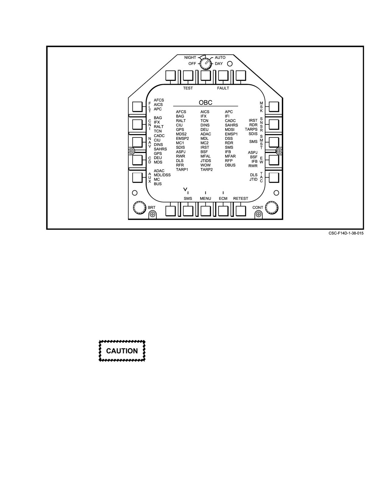
Figure 38Ć12.ĄOBC Basic Format
Depressing the INC button will display the IBIT code
the OBC tests. These should be cleared via the
followed by specific WRA codes for failures detected during
CLR pushbutton to allow subsequent fault reĆ
IBIT. Depressing MASTER RESET will clear the IBIT
porting in OFP. Acronyms present following
failure indications along with any previously existing
stand alone IBIT are generally valid.
resetable indications, but does not indicate that the detected
failures have been resolved. The DCP display will either be
38.3.3.3
Avionic Test Operation
blanked, or return to the IBIT ARM indication, depending on
Tests may be done in a sequence (preflight/in−flight,
MASTER TEST switch position, and the DFCS will enter
and retest sequence), or in groups (functional group), or on
OFP. IBIT failure codes will still be stored in the DCP display
an individual basis. For any equipment selected and validated
and can be recalled with the INC/DEC buttons until another
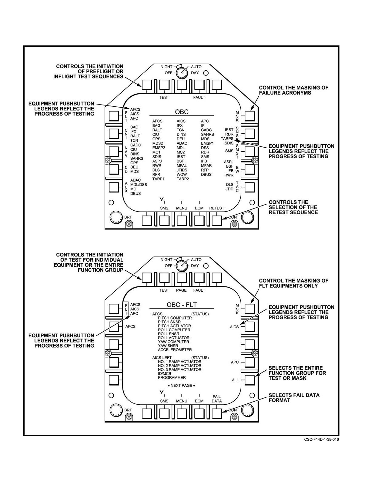
for test, the progress of testing is indicated on all OBC format
IBIT is run or aircraft power is secured
types that contain equipment pushbutton legends. Refer to
Figure 38−13 for format examples. Test progress is indicated
on the OBC formats as follows:
1. Equipment pushbutton legends appear bright and
Following an IBIT, MASTER RESET will clear
steady when a test cannot begin immediately beĆ
the IBIT failure indications including caution/
cause of a dependency with at least one other equipĆ
advisory lights, but does not ensure the failures
ment. When the dependency no longer exists, the
detected during IBIT are resolved. The DFCS
equipment is commanded to test and the pushbutton
should not be considered fully operational. Only
legend will then appear flashing.
the successful completion of another IBIT can
verify proper system operation.
2. Equipment pushbutton legends flash at bright intenĆ
sity when an equipment is in test.
Note
3. Equipment pushbutton legends appear steady at a
AFC acronyms following OBC are invalid
normal level of intensity when an equipment is not
because DFCS IBIT lasts longer than the rest of
in test.
38−33
ORIGINAL
NAVAIR 01−F14AAD−1
Figure 38Ć13.ĄFormat Examples
ORIGINAL
38−34
NAVAIR 01−F14AAD−1
Commanded BIT testing interferes with normal operaĆ
6.
The retest sequence is initiated through the OBC
tional modes of equipment. Testing can be initiated only
basic format by pressing the RETEST pushbutton
when equipment is powered up and ready. If equipment is
while the aircraft is on the ground or airborne.
currently not ready, equipment pushbutton legends will
WRAs are selected by the system for retest if the last
remain steady.
entry in the FHF indicates a NOT READY status
and if individual equipment interlocks are satisfied.
All testing is terminated by the system when any of the
Refer to BIT interlocks/restrictions for the equipĆ
following occurs:
ment applicable to this sequence.
1. The ACM guard is lifted.
7.
If interlock conditions/restrictions are not satisfied,
testing will not be initiated. Refer to paragraph
2. A weapon is selected.
38.3.3.3.3 for computer message descriptions.
3. A radar ACM mode is selected.
8.
If the interlock conditions are satisfied, the
4. Interlock status changes from those conditions satisĆ
RE−TEST pushbutton is boxed to indicate a valid
test selection and BIT is initiated in parallel or in
fied at the initiation of test.
sequential order for all WRAs in the sequence that
Note that not all tests can be terminated.
are powered on and ready.
38.3.3.3.1
Automatic Test Sequences
9.
At the completion of the RETEST sequence, the last
FHF entry
(indicating NOT READY) will be
There are three types of automatic test sequences, all
removed from the FHF for all equipment that
of which are initiated through the OBC basic format: in
currently indicates a status other than NOT READY.
flight, preflight, and retest. Each sequence allows the testing
of many WRAs with a single pushbutton. The system
10. Nominal test time varies based on the mix of
commands each WRA to test in a predetermined order so that
equipment. Maximum test time is 35 seconds (Note:
equipment conflicts are eliminated. Refer to BIT interlocks/
Test times may vary as a function of equipment
restrictions for the tests in each sequence.
status.)
1.
In−flight/preflight test sequences are initiated
11. Reselecting the RETEST pushbutton while the
through the OBC basic format by pressing the TEST
sequence is in progress will terminate test for
pushbutton while the aircraft is on the ground or airĆ
equipment still in test. Equipment that cannot be
borne. Depending on the flight status, either the
terminated will continue in test to normal compleĆ
in−flight or preflight test sequence will be initiated
tion. When all tests are completed, the RETEST
(refer to BIT interlocks/restrictions).
pushbutton is unboxed to indicate that the sequence
2.
If interlock conditions/restrictions are not satisfied,
is no longer in progress.
testing will not be initiated and a computer message
will be displayed to indicate the reason for rejection.
38.3.3.3.2
Function Group/Unit Test
Refer to paragraph 38.3.3.3.3 for computer message
descriptions.
OBC functional group formats allow groups of
functionally related or individual (i.e., unit) WRAs to be
3.
If interlock conditions are satisfied, the TEST pushĆ
selected for test. Refer to Figure 38−8. The OBC functional
button legend is boxed to indicate a valid test selecĆ
group formats are accessible from the OBC basic format:
tion and BIT is initiated in parallel or in sequential
FLT, CNI NAV, CD, AUX, SNSR, SMS, EW, and TAC.
order for all WRAs in the sequence that are powered
Group tests are initiated with the respective OBC
on and ready.
functional group format by pressing the ALL and TEST
4.
Nominal test sequence time for preflight is
69
pushbuttons. The ALL pushbutton legend is boxed to
seconds, and in flight is 35 seconds. (Note: Test
indicate its selection and is unboxed when deselected. Group
times may vary as a function of equipment status.)
testing is only initiated if the ALL pushbutton is boxed prior
to making the selection of the TEST pushbutton. Depending
5.
Reselecting the TEST pushbutton while the
on flight status, all WRAs that satisfy individual interlock
sequence is in progress will terminate test for WRAs
conditions will be initiated into test. Refer to Figure 38−7 for
that are still in test. WRAs that cannot be terminated
group test selects.
will continue in test until normal completion. When
all WRAs have completed test, the TEST
1. If interlock conditions/restrictions are not satisfied
pushbutton legend is unboxed to indicate that the seĆ
for at least one WRA, testing will not be initiated.
quence is no longer in progress.
38−35
ORIGINAL
NAVAIR 01−F14AAD−1
2. If interlock conditions are satisfied for at least one
Normally, OBC computer messages are displayed on
WRA, the TEST pushbutton legend is boxed or the
the pilot center MFD and the RIO MFD. If the pilot center
applicable OBC functional group format to indicate
MFD is powered off or failed, computer messages will be
a valid test selection and BIT is initiated in parallel
displayed on the pilot right MFD. These messages are
or in sequential order for all powered−on and ready
removed from the display head by pressing the ACK
WRAs in the sequence.
pushbutton, which is boxed to indicate that at least one
display message requires acknowledgment (refer to Figure
3. Nominal test times may vary as a function of the
38−14).
selected functional group and are based on the
equipment initiated to test (refer to Figure 38−4).
OBC/CSS messages are displayed on the MFD from
which the test selection is made and also displayed on the
4. Reselecting the ALL and TEST pushbuttons while
same MFD if a CSS format is presented. There are two types
the functional group test is in progress will termiĆ
of messages within this class: 3−second type, displayed for
nate test for equipment in test. Equipment that
3 seconds and then removed by the system; conditionally
cannot be terminated will continue in test until norĆ
removed type, displayed until either the applicable interlock
mal completion. When all equipment has completed
condition is satisfied, or until the format is changed (refer to
test, the TEST pushbutton legend is unboxed to indiĆ
Figure 38−15).
cate that testing is complete.
38.3.3.3.4
OBC−Related Warning/Caution/
Unit tests are initiated from any OBC functional group
Advisory Messages
format by pressing equipment and TEST pushbuttons. Any
number of equipment pushbuttons may be pressed prior to
Figure 38−16 shows acronyms that are displayed on
pressing the TEST pushbutton in order to test more than one
MFD3 in response to equipment failures or overheating.
item at the same time. For each selection, the pushbutton
legend is boxed to indicate selection and unboxed when
38.3.3.3.5
Failure History File Format
deselected. Only equipment with a boxed legend will be
The FHF format displays a history of WRA failures.
tested. Depending on flight status, all equipment that satisfies
There is a maximum of 10 entries per WRA for which the
individual interlock conditions will be initiated into test.
WRA failure status and the time of failure are displayed. The
Refer to Figure 38−7 for individual test selects.
time of failure is relative to the last time the system was cold
1. If interlock conditions/restrictions are not satisfied
started or SYSTEM RESET was pressed. The FHF is cleared
for at least one equipment, testing will not be
when the CLR pushbutton is pressed with preflight condiĆ
initiated.
tions satisfied. The preflight conditions are: weight on
wheels, TAS < 76 knots, pilot’s OBC discrete via the
2. If interlock conditions are satisfied for at least one
MASTER TEST panel, and handbrake set.
equipment, the TEST pushbutton legend is boxed
on the applicable OBC functional group format to
38.3.4
Joint Tactical Information Distribution SysĆ
indicate a valid test selection and BIT is initiated for
tem On−Board Check
all equipment that is powered on and ready.
JTIDS OBC can be selected whenever electrical power
3. Nominal test times may vary as a function of the seĆ
and cooling air are available. The JTIDS secure data unit
lected equipment initiated to test
(refer to
needs to be installed and loaded for JTIDS to pass OBC.
FigureĂ38−4).
Without the unit installed and loaded, JTIDS OBC will
4. Reselecting equipment and TEST pushbuttons
display a DDP fail. A JTIDS download is not required for
while test is in progress will terminate test for equipĆ
JTIDS OBC; however, if the MDL is loaded, a download is
ment still in test. Equipment that cannot be termiĆ
recommended. The selection of JTIDS OBC when not in sync
nated will continue in test until normal completion.
(receiving messages) will pass but the fail data will have bit
When all tests are complete, the TEST pushbutton
4 in word 11 and bit 8 in word 12 because no messages are
legend is unboxed to indicate that testing is no
received.
longer in progress.
The selection of JTIDS OBC will interrupt TACAN
data (momentary display of TACAN fail detected computer
38.3.3.3.3
OBC Display Messages
message) and initiate a TACAN self−test. This will disable
OBC display messages are shown on the MFDs in
TACAN steering and TACAN navigation updates, if seĆ
response to invalid test selections resulting from interlocks
lected; range will go invalid; bearing will display 270_; then
not being satisfied, interlocks changing, and for tests
range will display 000 miles and bearing 180_.
completed.
ORIGINAL
38−36
NAVAIR 01−F14AAD−1
COMPUTER MESSAGE
DESCRIPTION
PRE−FLT OBC COMPLETE
Displayed when the preflight OBC test sequence is completed. Message is
displayed if sequence completes normally or is terminated, or if interlock conditions
change.
IN−FLT OBC COMPLETE
Displayed when the in−flight OBC test sequence is completed. Message is
displayed if sequence completes normally or is terminated, or if interlock conditions
change.
RETEST COMPLETE
Displayed when the retest OBC sequence is completed. Message is displayed if
sequence completes normally or is terminated, or if interlock conditions change.
TEST COMPLETE
Displayed when a functional group test is completed. Message is displayed if
− <GROUP NAME>
group test completes normally or is terminated, or if interlock conditions change.
<GROUP NAME> appears as AUX, CD, CNI, FLT, NAV, EW, TAC, or IRST for the
functional group that completed test.
OBC SEQ ABORTED
Displayed when an OBC sequence (preflight or in−flight) is terminated through the
OBC BASIC format while it is in progress.
RETEST ABORTED
Displayed when a retest sequence is terminated through the OBC BASIC format
while it is in progress.
PILOT OBC DISABLE
Displayed when the Pilot’s MASTER TEST panel switch remains in OBC
10 seconds after commanded BIT completes for an equipment that required this
interlock to initiate test.
INTERLOCK ABORT
Displayed when an interlock condition changes state (i.e., no longer satisfied)
for an equipment that is already in test. Commanded BIT will be terminated for the
affected equipment.
CHALLENGE IFF
Displayed when the IFF Interrogator has not been challenged prior to the selection
of a test sequence. This message is displayed only once at the time
of the test sequence selection. If the system cold starts, or SYSTEM RESET is
pressed, this message will be displayed again when a test sequence selection
is made.
INVALID <WRA NAME>
Displayed when an equipment has an inconsistent firmware load, or is not
LOAD
compatible with the mission computer software load. The <WRA NAME> field
applies to the following equipment: MC1, MC2, CIU, SAHR, MDS1, MDS2, DEU,
INS, ADAC, SMS, RWR, ASPJ, RDR, SDIS, IRST
Figure 38Ć14.ĄOBC Computer Messages
38−37
ORIGINAL
NAVAIR 01−F14AAD−1
COMPUTER MESSAGE
DESCRIPTION
WOW NOT SATISFIED
Displayed when equipment is selected for test via a unit, inflight, or preflight test
selection, and the WOW (Weight−on/off−Wheel) interlock condition is not satisfied.
Testing will not be initiated for the selected equipment. Note that this message will
not be displayed for functional group or retest test selections.
TAS NOT SATISFIED
Displayed when equipment is selected for test via a unit, inflight, or preflight test
selection, and the TAS (True Air Speed interlock condition less than or greater
than 76 knots) is not satisfied. Testing will not be initiated for the selected equipĆ
ment. Note that this message will not be displayed for functional group or retest
selections.
MULTI INTLK NOT MET
Displayed when equipment is selected for test via a unit, inflight or preflight test
selection, and more than one (i.e., multiple) interlock conditions are not satisfied
(WOW, TAS, PARKING BRAKE, or MTP). Testing will not be initiated for the
selected equipment. Note that this message will not be displayed for functional
group or retest selections.
EQUIPMENT CONFLICT
Displayed when equipment is selected for test which conflicts with other equipĆ
ment already in test. These conflicts are primarily between equipment subordinate
to the CIU, between CIU subordinate equipment and the CIU itself, between DP1
and DP2, and between MC1 and MC2. Testing will not be initiated for equipment
that conflict operationally.
NO COMMANDED BIT
Displayed when equipment that does not support command BIT is selected
for test.
OBC SEQ IN PROGRESS
Displayed when equipment is selected for test that is the same as equipment
already in test as part of an OBC inflight or preflight test sequence. Testing for the
selected equipment will not be initiated.
RETEST IN PROGRESS
Displayed when equipment is selected for test that is the same as equipment
already in test as part of an OBC RETEST sequence. Testing for the selected
equipment will not be initiated.
MASTER TEST NOT SET
Displayed when equipment is selected for test through a unit or preflight test
selection and the pilot’s MASTER TEST panel switch is not set to OBC. This
message is displayed as long as an OBC or CSS format is presented, and
removed when the switch is set to OBC.
HANDBRAKE NOT SET
Displayed when equipment is selected for test via a unit or preflight test sequence
selection and the handbrake is not set. This message is continuously displayed
as long as an OBC or CSS format is presented and is removed when the handĆ
brake is set.
BAD JTID DATA LOAD
Displayed when JTIDS test is selected during initialization (Down Load)
of JTIDS.
TACAN FAIL DETECTED
Displayed for a TACAN failure or JTIDS NOT READY.
JTIDS FAIL DETECTED
Displayed for a JTIDS failure or JTIDS NOT READY.
Figure 38Ć15.ĄOBC/CSS Messages
ORIGINAL
38−38
NAVAIR 01−F14AAD−1
ACRONYM
DISPLAYED CONDITION
CAUSE
MC1
Mission computer No. 1 is NO GO or
Mission computer No. 1 is failed,
NOT READY.
or powered off.
MC2
Mission computer No. 2 is NO GO or
Mission computer No. 2 is failed,
NOT READY.
or powered off.
CIU
CIU is NO GO or NOT READY.
CIU is failed, or powered off.
INS
INS is NO GO or NOT READY.
INS is failed, or powered off.
IMU
IMU is not valid.
IMU is failed. Loss of inertial and attitude data
from INS.
GPS FAIL
GPS is NO GO or NOT READY
GPS failed, or powered off.
RWR
RWR is NO GO or NOT READY.
RWR is failed, or powered off.
FWD ASPJ
ASPJ receiver (low or high), ASPJ transmitter
ASPJ RECEIVER, TRANSMITTER,
(low or high) or processor is NO GO.
or PROCESSOR is failed.
AFT ASPJ
ASPJ processor, receiver augmentation or
ASPJ PROCESSOR, RECEIVER AUG,
transmitter augmentation is NO GO.
or TRANSMITTER AUG is failed.
MC1 HOT
Mission computer No. 1 overheated.
Possible loss of cooling air.
MC2 HOT
Mission computer No. 2 overheated.
Possible loss of cooling air.
ASPJ HOT
ASPJ is overheated.
Possible loss of cooling air.
CIU HOT
CIU is overheated.
Possible loss of cooling air.
DP1 HOT
DP1 is overheated.
Possible loss of cooling air.
DP2 HOT
DP2 is overheated.
Possible loss of cooling air.
SMS HOT
SMS is overheated.
Possible loss of cooling air.
RDR HOT
RDR is overheated.
Possible loss of cooling air.
HUD HOT
HUD is overheated.
Possible loss of cooling air.
RWR HOT
RWR is overheated.
Possible loss of cooling air.
DSS HOT
DSS is overheated.
Possible loss of cooling air.
DEU HOT
DEU is overheated.
Possible loss of cooling air.
MPS HOT
MPS is overheated.
Possible loss of cooling air.
IRST HOT
IRST is overheated.
Possible loss of cooling air.
SAHRS HOT
SAHRS is overheated.
Possible loss of cooling air.
JTID HOT
JTIDS R/T is overheated.
Possible loss of cooling air or a high JTIDS
transmit duty cycle.
IPF
JTIDS Interference Protection Feature detected
JTIDS is failed, a momentary glitch or 20% duty
failure.
cycle has been exceeded in Limit". Select IPF
Reset on JTIDS Control Panel.
SDU ALRM
JTIDS Secure Data Unit failure or no crypto
SDU fail or the crypto key is erased.
load.
Figure 38Ć16.ĄOBC−Related Warning/Caution/Advisory Messages
38−39
ORIGINAL
NAVAIR 01−F14AAD−1
38.4
COOPERATIVE SUPPORT SOFTWARE
3. Pressing the TM pushbutton allows CSS data to be
telemetered or down−linked to a ground−based
CSS allows capture and display of system data in real
station.
time and the optional recording of data from avionics
processors that are CSS compatible. CSS is typically used to
4. Pressing MC or MC2 allows CSS data to be stored
aid in troubleshooting system problems. The CSS compatible
in mission computer No. 1 or mission computer
processors include mission computer No.
1, mission
No.Ă2 memory, respectively, and is only accessible
computer No.
2, multifunction display system No.
1,
for future reference by the CSS function. A maxiĆ
multifunction display system No. 2, airborne data acquisition
mum of 300 blocks of CSS data can be stored in eiĆ
system, stores management processor, converter interface
ther mission computer. A block of data is saved
unit, data entry unit, infrared search and track system, joint
when a trap or block address function completes,
tactical information distribution system, and sensor display
and one block per second is saved for an active flyĆ
indicator set. Note that radar flycatcher displays are provided
catcher. This data will only be retained by the misĆ
on the programmable tactical information display.
sion computers until the system cold starts or is reĆ
set.
Note
5. Pressing the DSS pushbutton allows CSS data to be
The JTIDS processor only supports the flyĆ
recorded by the data storage set.
catcher functions
(start address, increment,
decrement, and disable).
The CSS OPER CODE page format (see Figure 38−18)
allows the optional selection of an operator code. This code
CSS supports the following modes, all of which are
is used to identify the operator/aircraft when CSS data is
selectable on the DEU: flycatcher, block address, and trap.
analyzed offline. The code is entered by pressing the
CSS data is displayed on the MFD CSS format. The CSS
corresponding numerics and then pressing ENT.
format is selected by pressing the FAULT pushbutton on the
OBC basic format and then pressing CSS on the MAINT
38.4.1.2
Flycatcher Operation
CURRENT FAILURES format.
Flycatcher mode allows memory contents for a seĆ
38.4.1
CSS Operation
lected processor to be continuously examined and displayed
on the MFD CSS format. The contents of 16 contiguous
The CSS page (see Figure 38−17), displayed on the
memory locations are displayed relative to a specified
DEU, allows the entry of DATA TYPE and OPER CODE
flycatcher memory start address, updated at a 1−second rate.
used for data recording purposes, and allows the selection of
A previously specified start address may be incremented or
all CSS modes including flycatcher, block address, and trap.
decremented by a fixed bias. Each processor supports only
All CSS data is displayed on an MFD CSS format, using
one flycatcher at a time.
pushbutton controls. Note that if the DEU is slaved to the
RIOĂMFD, selection of the CSS format on that MFD will
Flycatcher is initiated or terminated as follows, using
cause the CSS page of the DEU to be displayed.
the DEU (see Figure 38−19):
1. Select flycatcher by pressing FLY CATC on CSS
38.4.1.1
Data Recording Operations
page of DEU.
The CSS DATA TYPE page (see Figure 38−18) allows
the optional selection of a recording/storage device for the
2. Select processor to be examined by pressing one of
retention of data that is captured via a CSS mode. CSS data
the WRA pushbuttons on F−CATC page.
can be telemetered or recorded for offline analysis based on
one or more of the following selections:
3. Initiate flycatcher. Press STRT ADRS to allow entry
of starting memory address for selected processor
1. Pressing the AUX pushbutton allows CSS data to be
enter start address in hexadecimal with numeric
displayed on an auxiliary display (this function is
pushbuttons. Press ENT to complete address entry
not available).
and activate flycatcher.
2. Pressing the REC pushbutton allows CSS data to be
4. For flycatcher termination, press DSBL to deacĆ
recorded on a flight recorder, if one is installed in the
tivate current flycatcher.
aircraft.
5. Repeat steps 2 and 3 to initiate or terminate addiĆ
tional flycatchers for other processors.
ORIGINAL
38−40
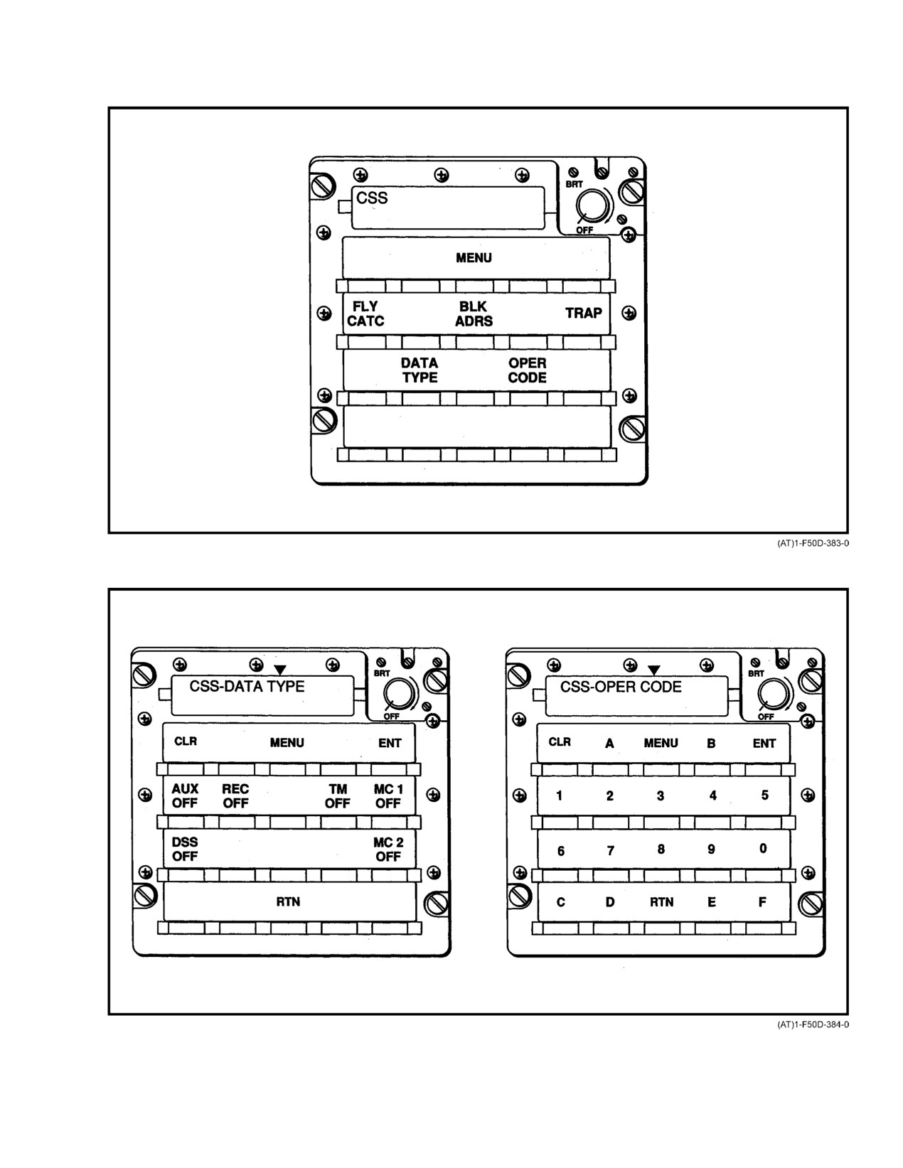
NAVAIR 01−F14AAD−1
Figure 38Ć17.ĄDEU CSS Page
Figure 38Ć18.ĄDEU Pages for Operator Code and Data Type
38−41
ORIGINAL
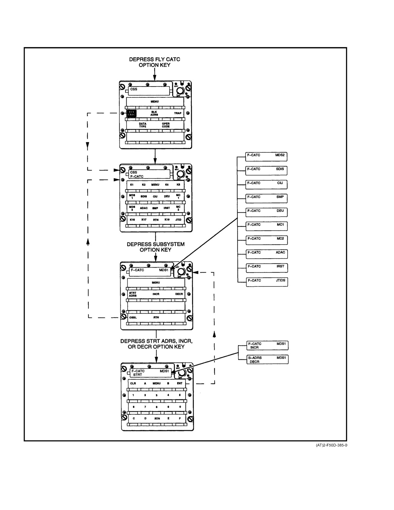
NAVAIR 01−F14AAD−1
Figure 38Ć19.ĄDEU Flycatcher Pages
ORIGINAL
38−42
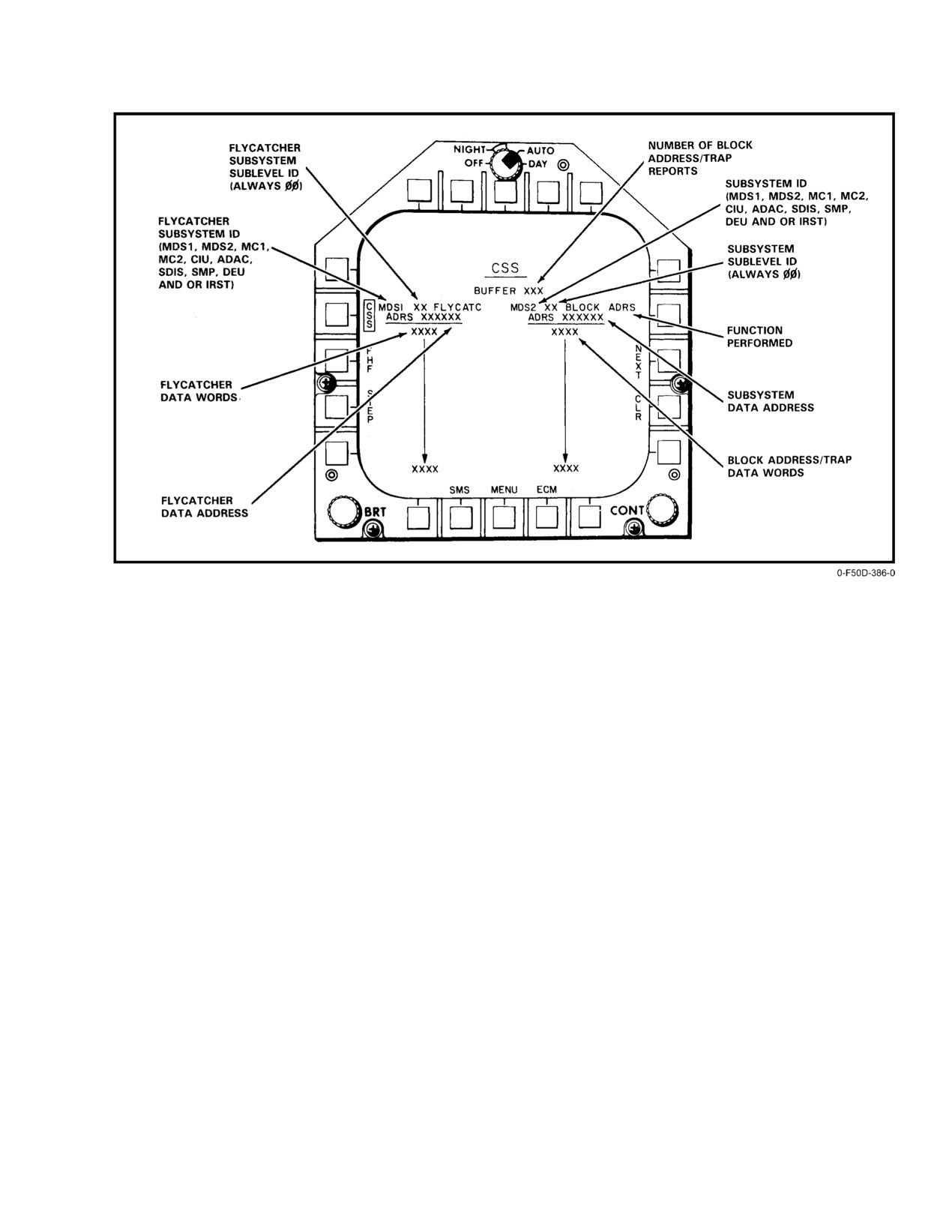
NAVAIR 01−F14AAD−1
Figure 38Ć20.ĄMD CSS Display Format
An active flycatcher can be biased by a fixed number
field will display flycatcher last selected, if any,
of memory locations, relative to the current memory address
when format is first displayed.
as follows, using the DEU (see Figure 38−19):
The messages shown in Figure 38−21 are displayed on
the RIO MFD computer message area in response to an
1. Select flycatcher by pressing FLY CATC on CSS
invalid flycatcher operation.
page of DEU.
2. Select INCR (to increment) or DECR (to decreĆ
38.4.1.3
Block Address/Trap Operation
ment) pushbutton. Enter bias value in hexadecimal
Block address allows the memory contents of a
with numeric pushbuttons and press ENT to comĆ
selected processor to be captured once upon its selection; trap
plete entry.
allows data to be captured once upon the satisfaction of a
selected algorithm. Data captured as a result of either mode
3. Repeat step 2 for subsequent entry of bias values for
is displayed on the MFD CSS format. The contents of 16
selected processor.
contiguous memory locations are displayed relative to a
Flycatcher data is displayed on the left half of the CSS
specified memory start address.
format anytime there is at least one active flycatcher as
Block address is initiated as follows, using the DEU
follows, using the MFD (see Figure 38−20).
(see Figure
38−22)(note that block address terminates
automatically after its activation):
1. Select CSS format on any MFD by pressing FAULT
pushbutton on OBC basic format and then pressing
1. Select block address mode by pressing BLK ADRS
CSS pushbutton on MAINT CURRENT
on CSS page of DEU.
FAILURES format.
2. Select system to be examined by pressing one of
2. Select STEP pushbutton to display 16−word block of
equipment pushbuttons on B−ADRS page.
flycatcher data associated with next processor that
has active flycatcher. Note that flycatcher data word
38−43
ORIGINAL
NAVAIR 01−F14AAD−1
MESSAGE (NOTE 1)
REASON FOR DISPLAY
E FLYCH ADD {SSSS}
Error in DEU entered flycatcher start address for the subsystem identified in
the {SSSS} field.
FLYCH EXISTS {SSSS}
Only one flycatcher can be active per subsystem. The subsystem is
identified in the {SSSS} field. In order to setup the next flycatcher, the
previous flycatcher must be disabled.
E FLYCH INC {SSSS}
Error in DEU entered flycatcher increment address for the subsystem
identified in the {SSSS} field.
N FLYCH IN {SSSS}
Error in DEU entry to increment, decrement or disable a flycatcher for a
subsystem that has no active flycatcher. The subsystem is identified in
the {SSSS} field.
E FLYCH DEC {SSSS}
Error in DEU entered flycatcher decrement address for the subsystem
identified in the {SSSS} field.
E NOT AVAIL
Flycatcher not available. System is not ready. JTIDS tape recording
(TOMs 21−27) enabled.
Note:
(1) {SSSS} identifies the affected CSS compatible subsystem.
Figure 38Ć21.ĄFlycatcher Error Messages
3. Enter start address in hexadecimal with numeric
a. Press ALGO to select algorithm that is used to
pushbuttons. Press ENT to complete the entry of
trigger the capture of data. Enter algorithm
data and to activate block address mode.
number with numeric keypads, and press ENT to
complete this entry.
4. Repeat steps 2 and 3 for additional block address
operations for other systems.
b. For each variable (i.e., V1, V2, V3) in selected
algorithm, press either an appropriate address
Trap is initiated or terminated as follows using the
pushbutton (V1 ADRS, V2 ADRS, V3 ADRS),
DEU (see Figure 38−23). There is a maximum of four taps per
or constant pushbutton (V1 CNST, V2 CNST,
processor:
V3ĂCNST). Both selections require numeric
entry defining address of variable or actual
1. Select trap mode by pressing TRAP on CSS page of
constant to be used in evaluation of algorithm.
DEU.
Enter value with numeric pushbuttons and then
press ENT to complete entry.
2. Select system to be examined by pressing one of
equipment pushbuttons on TRAP page.
c. Press DATA ADRS to allow entry of start address
for data. Enter address via numeric pushbuttons,
3. Enter trap number (00 to 98) where number can
and press ENT to complete entry.
represent existing trap or new one (depending on the
desired function).
d. Press COMP to complete the activation of tap.
4. Set up trap algorithm as indicated below, or press
5. Repeat steps 2 through 4 to initiate or terminate
DSBL to disable existing trap:
additional trap operations for other systems.
ORIGINAL
38−44
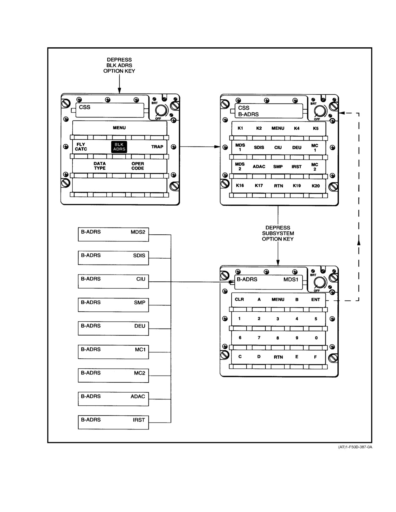
NAVAIR 01−F14AAD−1
Figure 38Ć22.ĄDEU Block Address Pages
38−45
ORIGINAL
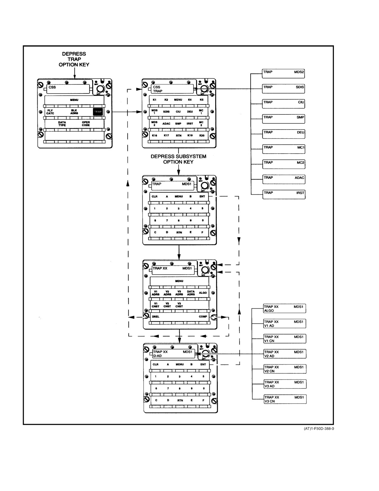
NAVAIR 01−F14AAD−1
Figure 38Ć23.ĄDEU Trap Pages
ORIGINAL
38−46
NAVAIR 01−F14AAD−1
MESSAGE (NOTE 1)
REASON FOR DISPLAY
E BLOCK ADD {SSSS}
Error in DEU entered block start address for the identified subsystem.
E TRAP ADD {SSSS} {NN}
Error in DEU entered trap start address for the identified subsystem and trap
number.
E 4 TRAPS {SSSS} {NN}
Current trap entry exceeds the maximum of 4 allowable traps per subsystem.
E TRAP VAR {SSSS} {NN}
Error in DEU entered trap variable address for the identified subsystem and
trap number.
E TRAP ALGO {SSSS} {NN}
Error in DEU entered algorithm code for the identified subsystem and trap
number.
NO TRAP NO. {SSSS} {NN}
Error in DEU entered trap number that is selected to be disabled.
TRAP TRU IN {SSSS}
Trap in identified subsystem has been triggered. Contents of the captured
data block can be displayed on the CSS format.
Note:
(1)
{SSSS} identifies the affected CSS compatible subsystem. {NN} identifies a trap number ranging between
1 and 4.
Figure 38Ć24.ĄBlock Address/Trap Error Messages
Block address and trap data are displayed on the right
The messages shown in Figure 38−24 are displayed in
half of the MFD CSS format when there is at least one block
the computer message area of the RIO MFD in response to
of data to be reported. As a maximum, only the last 15
invalid block address or trap operations.
block−address and trap reports will be retained by this
function. Displays are selected as follows:
38.5
RADAR SYSTEM BUILT−IN TEST
Radar system BIT detects AN/APG−71 radar system
1. Select CSS format on any MFD by pressing
hardware faults and provides assessment of tactical radar
FAULTĂpushbutton on OBC basic format, and then
mode availability. BIT has four major capabilities:
pressing CSS pushbutton on MAINT CURRENT
FAILURES format.
1. Fault detection uses computer−controlled and RIO−
initiated tests to detect failures in flight or on the
2. Press NEXT pushbutton to display next data report.
deck.
The number of block−address/trap reports indicates
if any additional reports of data are available for
2. Fault isolation allows isolation of a detected system
display and is decremented upon each depression of
failure by indicating DP and the suspect WRA or
NEXT pushbutton. Note that block−address/trap
group of WRAs.
data−words field will display last selected block of
data, if any, when format is first displayed. Repeat
3. DMA provides a pass, fail, or degraded evaluation
this step as necessary to display each report.
of the operational modes.
3. Press CLR pushbutton to clear any data reports. This
4. CM automatically provides the RIO with a warning
action inhibits display of any remaining reports and
when system failures occur during tactical modes.
resets the number of block−address/trap reports to
zero.
38−47
ORIGINAL
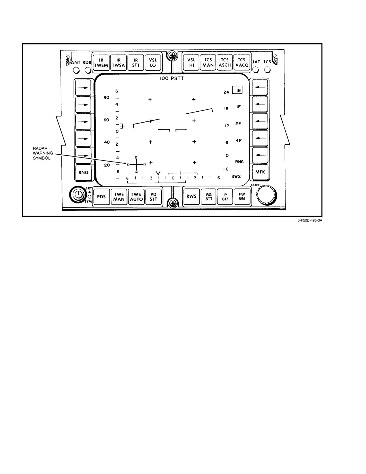
NAVAIR 01−F14AAD−1
Figure 38Ć25.ĄDD Radar Warning Maltese Cross
BIT provides indication of AN/APG−71 radar funcĆ
38.5.1
BIT Modes
tional status for ground−level maintenance and airborne
BIT allows the flightcrew to quickly assess radar set
operation. Prior to aircraft employment, or following an
status, identify hardware faults, and take the corrective
airborne mission, the groundcrew can execute BIT to
action. This assessment includes a radar confidence test
determine radar set status. Corrective maintenance action
verification of controls and displays functionality, and, as
recommendations are provided on the maintenance display.
necessary, confirmation that the television camera set is
This display indicates the detected hardware failure(s) along
operational.
with replacement recommendations for associated WRA(s).
During tactical operation, the RIO will be alerted to
The following BIT modes are available:
any anomalies that will impact radar or aircraft operation. A
1. Operational readiness test.
Maltese cross is displayed in the lower left−hand quadrant of
the DD if the radar has failed and/or the transmitter is not
2. Computer and displays mode test.
radiating (except in sniff mode). The Maltese cross is also
3. Initiated radar test.
displayed when the radar is in standby or during initiated
display test (Figure 38−25). The cross is not tied to the WOW
4. Initiated displays test.
switch, and will not be displayed solely for a WOW
5. Television camera set test.
condition. Radar anomalies will appear in the lower left
quadrant of the PTID as two−character acronyms. Aircraft
6. Digital display built−in self−test.
anomalies will appear on the PTID as three−character
7. Initiated special test.
acronyms, displayed below the radar acronyms. Acronyms
will be displayed continuously while the failure condition
8. Test−target BIT.
exists. If multiple failures occur, the appropriate acronyms
will be automatically cycled at a 2−second rate. More detailed
9. Continuous monitoring.
failure information is available on the continuous monitor
maintenance display. The RIO can initiate BIT at any time to
confirm that hardware status is unchanged.
ORIGINAL
38−48
NAVAIR 01−F14AAD−1
38.5.1.1
Operational Readiness Test
38.5.1.2
Computer and Displays Mode Test
ORT is automatically initiated when aircraft power is
CDM is automatically initiated when aircraft power is
applied to the radar, with the sensor hand control in either
applied to the radar with the SHC in CMPTR. CDM is
STBY or XMIT or if a radar power interruption occurs for
interruptible by pressing the PGM RST pushtile on the DD.
longer than 2.65 seconds. This radar confidence test includes
This radar confidence test includes a subset of the tests
tests of radar computers, RF subsystems, system interfaces,
performed during ORT. It differs from ORT in that the
and target detection capability. ORT requires nominally 3.5
antenna hydraulics and transmitter subsystem are not tested.
minutes to complete (including 3 minutes for transmitter
CDM requires, nominally, 2.5 minutes to complete (the
warmup), but could take as long as 7 to 8 minutes if radar
3−minute transmitter warmup delay is not required). At the
functions are degraded. When ORT has completed, the DMA
completion of CDM, the degraded mode assessment display
display is automatically displayed on the PTID and the BIT
is automatically displayed on the PTID, and the BIT menu
menu will appear on the DD. The DMA algorithm provides
will appear on the DD. The DMA algorithm will give an
an evaluation of the working status of tactical modes. If
evaluation of the working status of tactical modes. If
additional information is required, the maintenance display
additional information is required, the maintenance display
can be selected from the BIT menu.
can be selected from the BIT menu.
At the completion of ORT, the following tests can be
At the completion of CDM, the following tests can be
selected from the BIT menu on the DD: radar test, displays
selected from the DD BIT menu: radar test; display, test,
test, television camera set test, special test or test target. If no
television camera set test, special test or test target. If no
further testing is required, a tactical mode can be entered
further testing is required, a tactical mode can be entered
directly by selecting the DD pushtile for the desired mode.
directly by selecting the DD pushtile for the desired mode.
If ORT is running when a tactical situation arises, the
38.5.1.3
Initiated BIT (IBIT)
RIO can abort ORT by pushing the PGM RST button in the
lower right corner of the DD. ORT abort is not recognized
The IBIT mode contains five submodes: radar BIT,
until after the initialization phase is complete (5 seconds or
displays BIT, television camera set BIT, digital display
less). To report that ORT has been aborted, the CM acronym
built−in self−test, and special tests BIT.
OA is displayed in the lower left position of the PTID and the
event is recorded in the failure history file. The system will
38.5.1.3.1
Radar BIT
transition to 5−nm pulse search. The 3−minute transmitter
Initiated radar test (RDR) allows retest of the radar
warmup period will, however, still be in effect. This means
system. If the SHC is in either STBY or XMIT, radar BIT will
that the system capabilities will be limited to a nonradiation
be the same as ORT (with the exception that the 3−minute
mode until warmup is complete. The system may have some
transmitter warmup delay is not required). Consequently,
performance degradation because of insufficient calibraĆ
radar BIT execution time is shorter. If the SHC is in CMPTR,
tions. These calibrations are normally executed during the
radar BIT will be the same as CDM.
ORT sequence. Possible radar performance degradations are
as follows:
Radar BIT is initiated by depressing the MFK pushtile
on the DD to obtain the radar modes menu, selecting the
1. LPRF
pushtile adjacent to BIT to obtain the BIT submenu, and then
depressing the pushtile adjacent to RDR on the BIT menu.
a. Short pulse Up to 500−foot range bias.
Test execution requires approximately 2.0 minutes, and is
interruptible by a program restart (depressing PGM RST
b. Pulse compression Up to 2−nm range bias.
pushtile on the DD), another BIT selection, or a radar mode
selection.
2. HPRF RWS and PDS perform as required.
3. RAM RAM accuracy may be degraded.
38.5.1.3.2
Displays BIT
DISP is a controls and displays subsystem confidence
4. PDSTT/RGSTT Noise jammer problem will
check. The PTID and DD display a predefined set of static
occur first time until periodic calibrations are perĆ
and dynamic symbology for evaluation of symbol intensity,
formed. These calibrations shall be performed
completeness, contrast, and motion. Displays BIT symbolĆ
within 5 minutes of the ORT.
ogy is dependent on the PTID mode switch setting and DD
keypad entry. The RIO must confirm visually that this
subsystem is functioning properly.
38−49
ORIGINAL
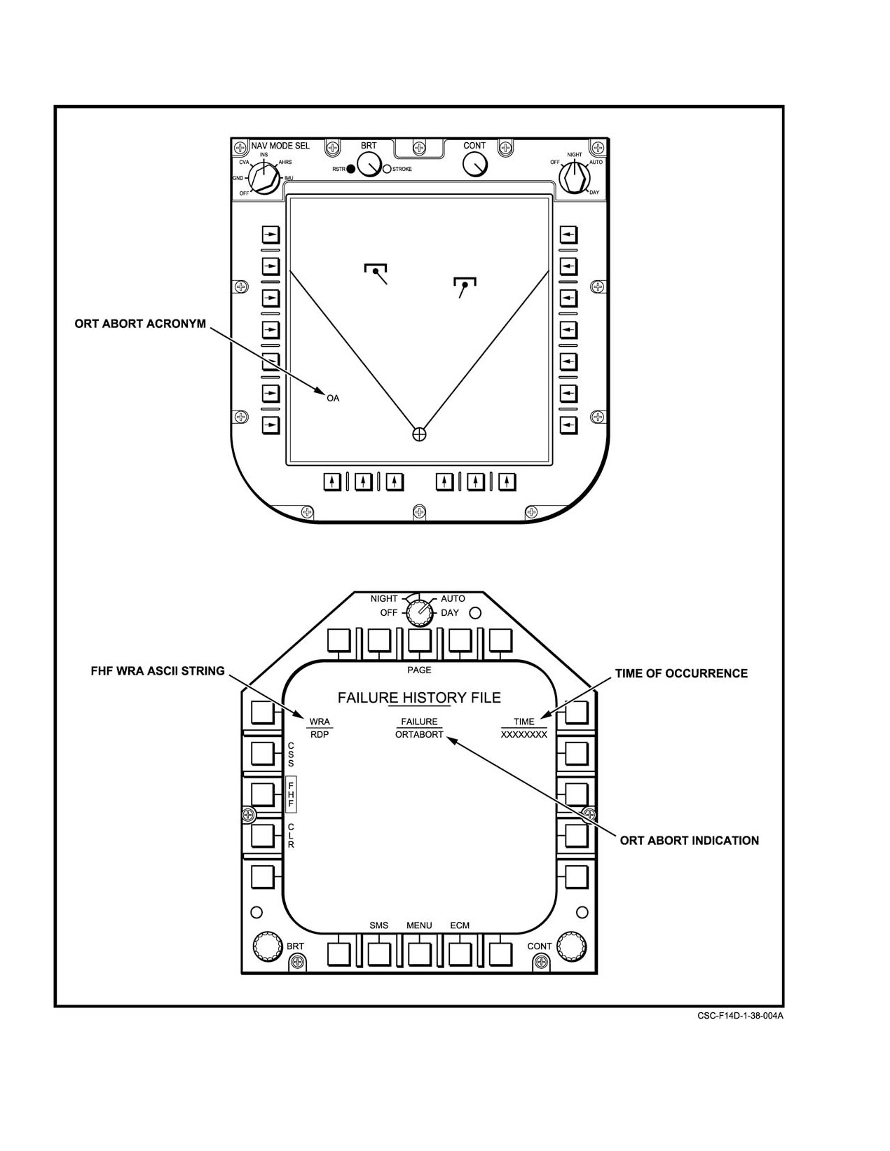
NAVAIR 01−F14AAD−1
Figure 38Ć26.ĄMFD/PTID ORT Abort Displays
ORIGINAL
38−50
NAVAIR 01−F14AAD−1
Displays BIT is initiated by depressing the MFK
processing, and is playing reasonably sized targets. It is
pushtile on the DD to obtain the radar modes menu, selecting
available in, and can be used to check the operation of low,
the pushtile adjacent to BIT to obtain the BIT submenu, and
medium, or high PRF tactical modes. Test target entry is
then depressing the pushtile adjacent to DISP on the BIT
indicated by a test target display on the lower left position of
menu. Displays BIT is interruptible by a program restart
the PTID.
(depressing PGM RST pushtile on the DD), another BIT
To initiate test target BIT, MFK pushtile on the digital
selection, or a radar mode selection.
display is depressed, selecting the BIT menu. The test target
is selected by depressing the button adjacent to TEST TGT.
38.5.1.3.3
Television Camera Set BIT
To enable the location for test target injection, the pushtile
The TCS test verifies the status of the television camera
adjacent to RDM TGT or RCVR TGT is depressed. To
set. The capability of the TCS slave modes is verified, the
terminate the test target BIT, the pushtile adjacent to the
mechanical tracking functions (i.e., slewing and track) are
enabled target injection location is reselected.
checked, and the radar−related TCS support functions are
monitored. Detected faults are displayed on the PTID at test
38.5.1.5
Continuous Monitoring (CM)
completion.
CM periodically samples mission essential radar set
TCS TEST is initiated by depressing the MFK pushtile
signals during tactical operation, and informs the RIO of
on the DD to obtain the radar modes menu, selecting the
detected problems.
pushtile adjacent to BIT to obtain the BIT submenu, and then
CM performs passive monitoring of key radar signals,
depressing the pushtile adjacent to TCS on the BIT menu.
a one−quarter/second rate. These signals include power
TCS testing is interruptible by a program restart (depressing
faults, overtemperature indicators, BIST status (i.e., equipĆ
PGM RST pushtile on the DD), another BIT selection, or a
ment ready) signals, processor load status, transmitter peak
radar mode selection.
power, calibration failures, antenna hydraulic interlocks, and
transmitter interlocks.
38.5.1.3.4
Digital Display Built−In Self−Test
(BIST)
Radar anomalies appear on the PTID, in the lower left
quadrant as two character acronyms. Acronyms will be
The DD has a standalone BIST capability that must be
displayed continuously while a failure condition exists. If
initiated and evaluated by the RIO. It tests DD functions as
multiple failures occur, the appropriate acronyms will be
well as its discrete interfaces with the sensor control unit,
automatically updated at a 2−second rate. When an acronym
sensor hand control, and PTID.
is displayed, the RIO can select the LM maintenance display
DD BIST is initiated by depressing the C/D TEST
to obtain more detailed information on the specific unit that
pushtile on the radar control panel portion of the digital
has a malfunction or anomaly. The RIO can also initiate BIT
display. When in flight continuous depression of the C/D
at any time to confirm that hardware status is unchanged.
TEST pushtile clears DD display and initiates BIST. Release
Aircraft system anomalies will appear on the PTID, in
causes the DD to revert to tactical operation. When not
the lower left quadrant directly below the radar CM
airborne, the first depression clears the DD display and
acronyms, whenever a fault is detected. Corresponding
initiates BIST; the second depression causes DD to revert to
failure acronyms will be displayed for 2 seconds.
tactical operation.
38.5.2
Radar BIT Operation
38.5.1.3.5
Special Tests BIT
The radar BIT function is contained in the RDP. This
Initiated SPL TEST is designed to validate the
specialized radar computer provides necessary timing and
operation of a specific radar submode or subfunction, and is
control signals to F−14D radar subsystems to conduct various
used primarily for maintenance purposes. These tests are
tests. BIT testing is generally independent of RIO interĆ
initiated with selection of the SPL TEST pushtile on the BIT
action, with the exception of some manual switch settings,
menu, selection of the NBR pushbutton on the DD keypad,
such as those on the SHC, which are not software
entering the appropriate test number and then pushing the
controllable.
ENTER button.
BIT execution can be either automatic or operator
38.5.1.4
Test Target BIT
initiated. Upon application of aircraft radar power, ORT is
automatically initiated. The RIO either switches the SHC
The test target function is a RIO activated and
from OFF to CMPTR (to start CDM execution), or STBY or
evaluated end−to−end test of the radar system. It can be used
XMT (to start ORT execution). After powerup, CDM or ORT
to quickly verify that the radar system is capable of detecting,
38−51
ORIGINAL
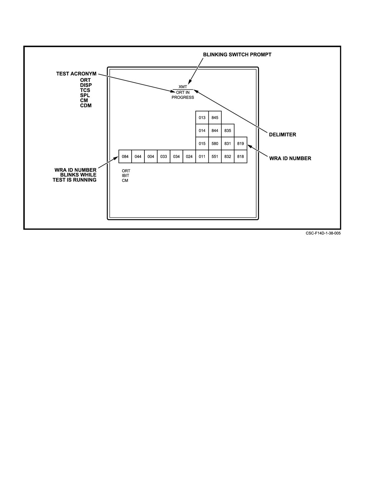
NAVAIR 01−F14AAD−1
Figure 38Ć27.ĄTest−in−Progress Display
may be aborted by pressing the PGM RST button on the lower
38.5.2.1
BIT Display Formats
right corner of the DD. If CDM/ORT is not aborted, ORT
BIT displays provide feedback on test progress,
requires nominally
3.5 minutes to complete and CDM
required RIO actions, pass/fail status, detected faults, and
requires nominally 2.5 minutes to complete.
maintenance action recommendations. These displays inĆ
The test−in−progress display is presented on the PTID
clude the test in progress, BIT menu, degraded mode
(see Figure 38−27). The WRA unit designators blink for those
assessment, maintenance display, test target CM, TCS test,
units that are undergoing test. Approximately 3 minutes after
DD BIST, displays test (static and dynamic), and special test.
radar turn−on, an XMT acronym at the top of the PTID
prompts the RIO to switch to XMT, if the SHC switch is in
38.5.2.1.1
Test−in−Progress Display
STBY. The RIO has 25 seconds to respond. Failure to do so
The test−in−progress PTID display is presented upon
within the allotted time results in bypassing the system
initiation of ORT, CDM, or IRT (see Figure 38−27). This
transmitter test. If the RIO responds in time, the transmitter
display provides status on WRA testing progress, OBC,
test is executed and the transmitter subsystem unit group
continuous monitor failures, missile channel selection, and
blinks, indicating that testing is in progress. At the compleĆ
the DPs from previous ORT, CDM, IRT, or CM tests (if power
tion of ORT (and CDM) DMA is presented on the PTID. This
was not interrupted to the radar). The appropriate WRA
display provides an evaluation of the working status of the
reference designators blink for units undergoing test. WRA
tactical modes. If the RIO desires more detailed information,
designators and their corresponding common names are
the maintenance display can be selected by depressing the
listed in Figure 38−28.
DD pushtile adjacent to MAINT DISP. This display provides
test fail or pass status, the detected malfunctioning WRAs,
At the completion of ORT, CDM or IRT, the degraded
and the associated DPs. DPs provide specific detailed
mode assessment format (described in paragraph 38.5.2.1.3)
information on the faults detected within a particular unit. In
is displayed on the PTID.
order to get back to the DMA display, the pushtile adjacent
to MAINT DISP is reselected.
ORIGINAL
38−52
NAVAIR 01−F14AAD−1
The symbols that appear on the displays and the
WRA ID#
corresponding modes or function named for the basic DMA
004
−
Radar master oscillator (RMO)
are as follows:
011
−
Radar transmitter (TX)
1. PDS Pulse Doppler search.
013
−
Collector power supply (CPS)
2. RWS Range while search.
014
−
Beam power supply (BPS)
3. TWS Track while scan.
015
−
Solenoid power supply (SPS)
4. PDSTT Pulse Doppler single−target track.
024
−
Radar receiver (RCVR)
033
−
Radar antenna (ANT)
5. MRL Manual rapid lock−on.
034
−
Analog signal converter (ASC)
6. PAL Pilot automatic lock−on.
044
−
Advanced Radar signal
7. PSTT Pulse single−target track.
processor (ARSP)
8. RGSTT Range−gated single−target track.
084
−
Advanced Radar data processor
9. VSL Vertical scan lock−on.
(ARDP)
551
−
Digital display (DD)
10. PLM Pilot lock−on mode.
580
−
Programmable tactical information
11. PS Pulse search.
display (PTID)
12. GM Ground map.
818
−
Television camera set (TCS)
13. AGR Air−to−ground ranging.
819
−
Radome interlock circuitry (RIC)
831
−
Mission computer 2 (MC2)
14. BIT Built−in test.
832
−
Mission computer 1 (MC1)
For a more detailed description of the pass/fail status
835
−
Converter interface unit (CIU)
of ORT, CDM, or IRT, the maintenance display format
844
−
Sensor control unit (BCU)
(described in paragraph 38.5.2.1.4) is called up on the PTID
by depressing the pushtile adjacent to MAINT DISP (on the
845
−
Sensor hand control (SHC)
DD BIT menu). The DMA display format is restored by
reselecting the pushtile adjacent to MAINT DISP.
Figure 38Ć28.ĄWRA Common Names and Designators
Note
38.5.2.1.2
BIT Menu Display Format
After a tactical mode is entered, the DMA disĆ
play format cannot be restored.
The DD BIT menu is presented at the completion of
ORT or CDM, and provides allowable RIO BIT test
38.5.2.1.4
Maintenance Display Format
selections
(see Figure 38Ć29). The RIO can initiate the
following tests from this menu: displays test, radar test, TCS
The maintenance display is obtained by depressing the
test, special test, or test target. These tests are initiated by
DD BIT menu pushtile adjacent to MAINT DISP. It can be
depressing the pushtile adjacent to the desired test name on
selected during displays test, a tactical radar mode, or special
the DD. A highlighted box appears around the test name on
test. It can also be obtained by transitioning from the DMA
the DD to indicate that a test has been selected. Tests cannot
display (described in paragraph 38.5.2.1.3).
be initiated concurrently.
The maintenance display provides test pass or fail
The BIT menu can also be accessed while the radar is
status to the RIO. If no faults are detected, a RDR PASSED
in a tactical mode by depressing the MFK pushtile to obtain
indication is displayed near the top of the PTID, no WRA
the radar mode menu and then selecting BIT.
designators are displayed, and a checkmark appears adjacent
to the appropriate test (see Figure 38−31). If a failure is
38.5.2.1.3
Degraded Mode Assessment Format
detected, a RDR FAILED indication is displayed near the top
of the PTID, and the WRAs recommended for replacement
The display shown in Figure 38−30 is provided on the
along with the associated DPs, are displayed on the PTID
PTID at the completion of DMA. The purpose of DMA is to
(seeĂFigure 38−32). The WRA designators and their correĆ
give the RIO an evaluation of the working status of tactical
sponding common names are listed in Figure 38−28.
modes. An acronym for each mode is displayed on the PTID
and a pass (4), fail
(X), degraded
(p), or unevaluated
indication is presented with each acronym.
38−53
ORIGINAL
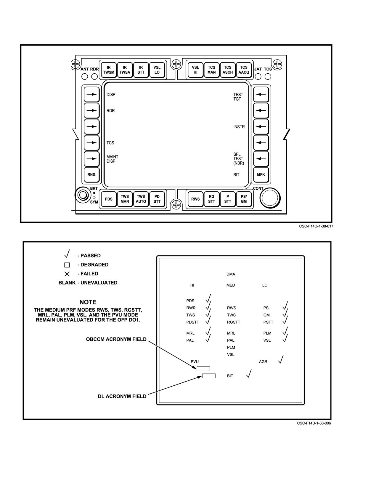
NAVAIR 01−F14AAD−1
Figure 38Ć29.ĄBIT Menu Display Format
Figure 38Ć30.ĄDegraded Mode Assessment Format
ORIGINAL
38−54
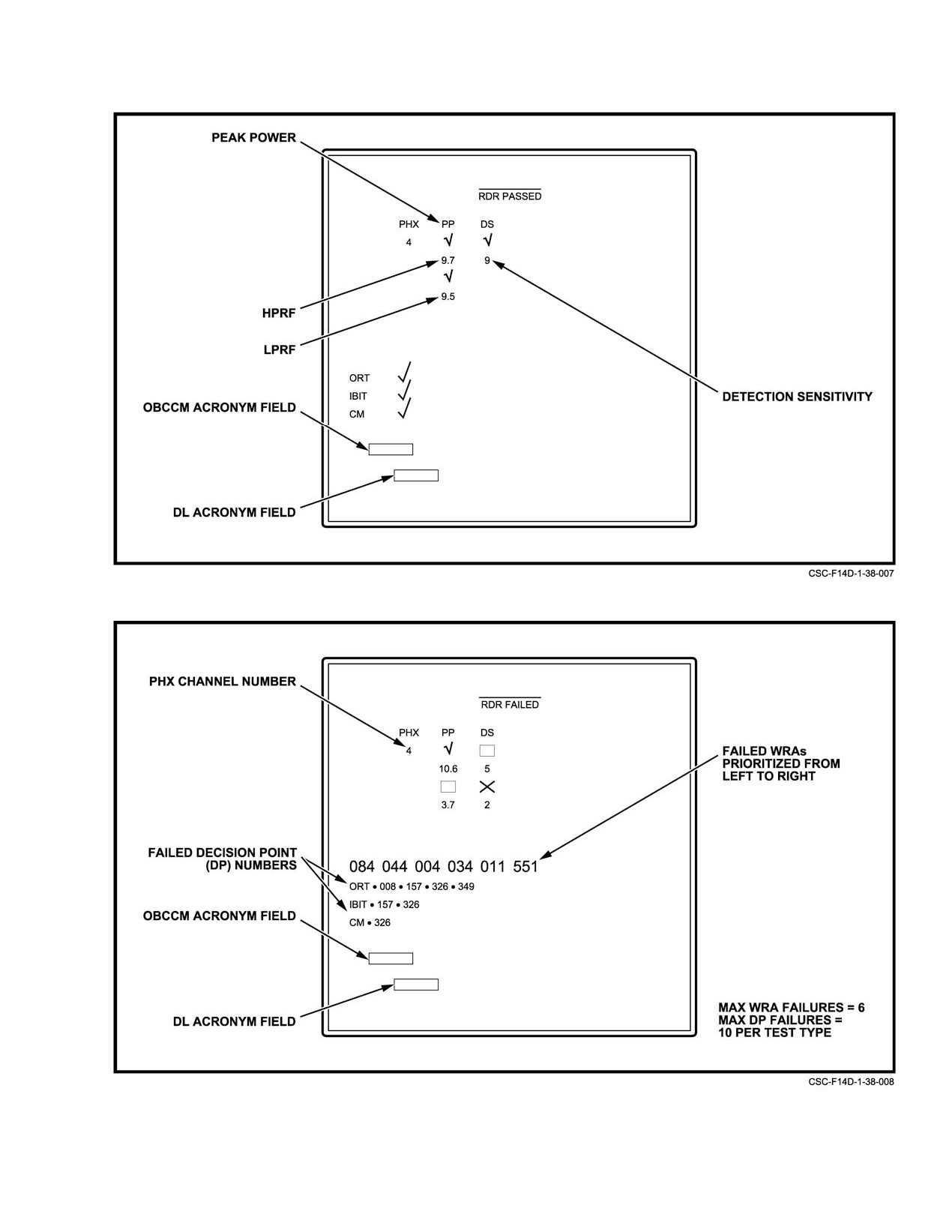
NAVAIR 01−F14AAD−1
Figure 38Ć31.ĄMaintenance Display Format (Test Complete)
Figure 38Ć32.ĄMaintenance Display (Test Complete)
38−55
ORIGINAL
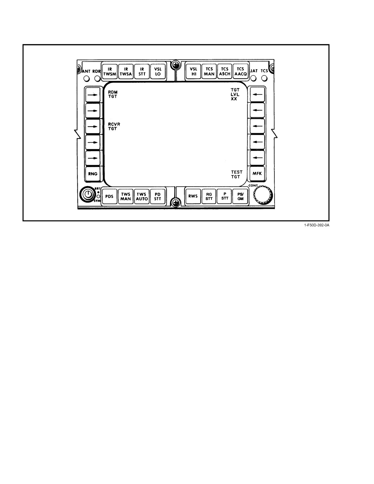
NAVAIR 01−F14AAD−1
Figure 38Ć33.ĄTest Target Menu
Detected failures are isolated to a maximum of six
injected directly through the receiver, thus bypassing the
WRAs. A maximum of 10 DPs are displayed adjacent to the
antenna. To terminate test target BIT, the pushtile adjacent to
test that was performed: ORT, IBIT (radar test, displays test),
the enabled test target injection location is reselected.
or CM.
The RIO can now select any tactical mode by
Values for detection sensitivity and peak power for
depressing the DD pushtile for the desired mode. The radar
HPRF and LPRF modes are displayed on the PTID along with
test target will be processed and displayed on the DD and
the AIM−54 or AIM−7 channel being tested.
PTID just as any newly detected target in the mode being
tested would be.
38.5.2.1.5
Test−Target BIT
In addition to testing the operation of the various
The test−target function is an end−to−end test of the
modes, the test target can also be used to check many radar
radar system, initiated and evaluated by the RIO. It can be
controls
(such as display controls) and verify computer
used to quickly verify that the radar system is capable of
functions such as hooking. For example, the RIO can hook
detecting, processing, and displaying reasonably sized
the test target (which first appears as an unknown target) on
targets. It is available in and can be used to check the
the PTID; designate it hostile
(noting symbol change);
operation of low, medium, or high PRF tactical modes.
initiate single−target track
(noting operation of ANT and
RDR indicator lamps); enter data pertaining to the target; and
To initiate the test target, the DD MFK pushtile is used
even test the track hold function after deselecting the test
to select the BIT menu. The test target is selected by
target.
depressing the button adjacent to TEST TGT. The test−target
menu is displayed on the DD (see Figure 38−33). The test
All targets have nominal initial values inserted for
target can be injected in two places depending on RIO switch
range, range−rate, and target power level. HPRF targets have
activation. By depressing the pushtile adjacent to RDM TGT,
initial range set to 20 miles and range−rate set to 800 knots
the target is injected through the radome radar test horn and
(closing). LPRF targets have initial range set to 18 miles,
is received and processed through the antenna array. By
with the DD range scale set to 20 or greater, or 4.5 miles, with
depressing the pushtile adjacent to RCVR TGT, the target is
the DD range scale set to 5 or 10.
ORIGINAL
38−56
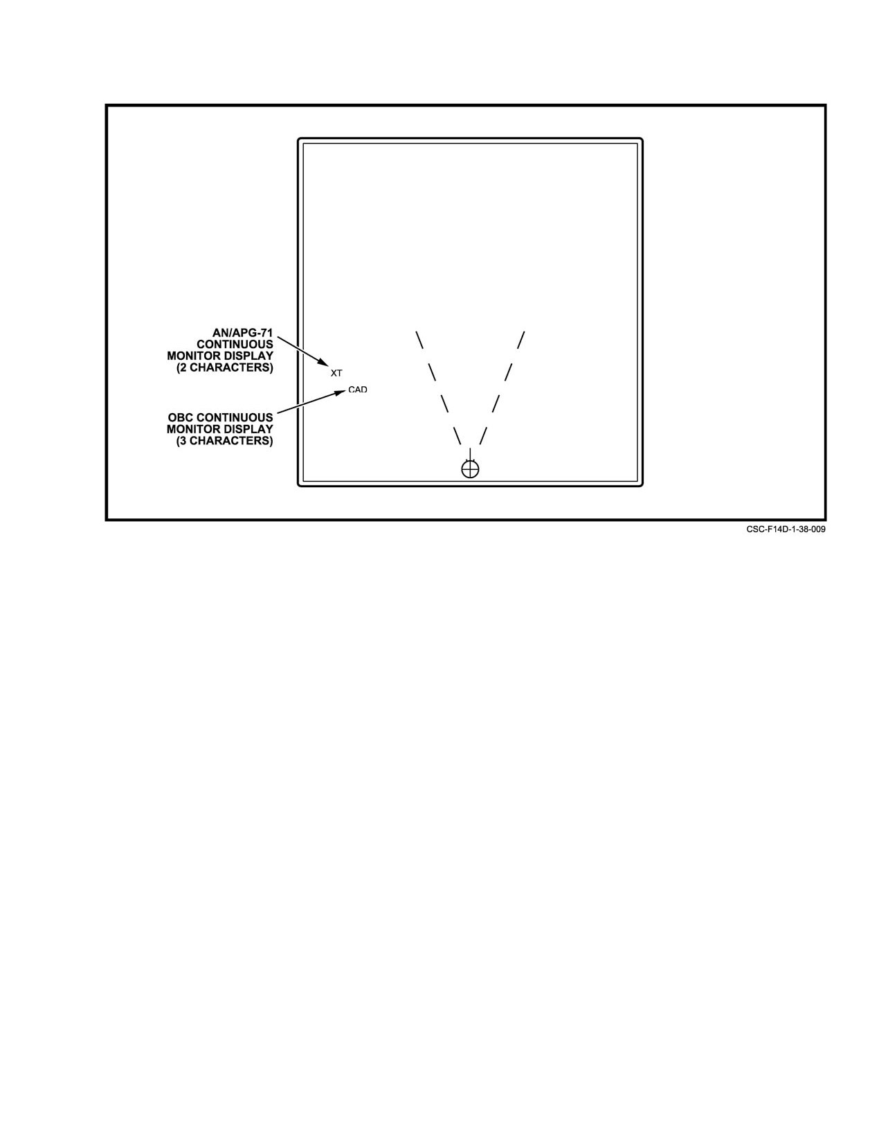
NAVAIR 01−F14AAD−1
Figure 38Ć34.ĄContinuous Monitor Display
Target power level selection can be entered manually
for MM) appear for 2 seconds when corresponding equipĆ
after enabling test−target BIT. A power level is selected by
ment is failed. The acronym MM overrides any previously
depressing the pushtile adjacent to TGT LVL and entering the
displayed acronym for 4 seconds. The corresponding acroĆ
following keyboard command:
nym is masked when an equipment is masked through the
MFDs.
Low values of X are correlated with weak target returns
and allow for testing the radar’s sensitivity. High values of X
A list containing the OBCCM acronyms that may
are correlated with strong target returns.
appear as a result of aircraft CM failures is shown in
FigureĂ38−36.
38.5.2.1.6
CM Display Format
38.5.2.1.7
TCS Test Format
CM fault detection is an integral part of the tactical
radar display. A two−character acronym is displayed in the
The TCS test is a RIO initiated test of the TCS and
lower left quadrant of the PTID whenever a fault is detected
associated switches. It is initiated by depressing the DD MFK
(see Figure 38Ć34). This acronym is continually displayed
pushtile to obtain the radar modes menu, selecting the
while the failure condition exists. If multiple failures occur,
pushtile adjacent to BIT to obtain the BIT submenu, and then
failure acronyms will cycle at a 2−second rate. The RIO can
depressing the pushtile adjacent to TCS. TCS testing is
obtain more detailed failure information by accessing the
interruptible by a program restart (DD PGM RST pushtile),
BIT menu on the DD (depressing MFK pushtile) and
another BIT selection, or a radar mode selection.
depressing the pushtile adjacent to MAINT DISP. The RIO
The TCS test function consists of 15 major subtests,
can also initiate BIT at any time to confirm that the hardware
that occur in the following order: TCS on−board checkout,
status is unchanged.
TCS cursor, manual acquisition, TCS slaved to radar, TCS
A list containing two letter acronyms that may appear
return to search, TCS slaved to radar pointing accuracy test,
as a result of radar CM failures is shown in Figure 38−35.
TCS slaved to computer pointing accuracy test, automatic
search, TCS scan pattern test independent mode, radar miles,
Aircraft anomalies will appear on the PTID (lower left
with the DD range scale set to 20 or greater, or 4.5 miles, with
quadrant directly below the radar CM acronyms) whenever
the DD range scale set to
5 or
10 slaved to TCS,
a fault is detected (see Figure 38−35). All acronyms (except
38−57
ORIGINAL
NAVAIR 01−F14AAD−1
ACRONYM
EQUIPMENT
ACRONYM
EQUIPMENT
BB
Computer bus backup enabled
MX
RMX status word error
(DP 409)
(DPs 40, 42, 44)
BF
PTID buffer overload (DP 283)
OA
ORT has been aborted
CA
Calibration failure
OH
Overheat (RMO, RX, DD, RDP, RSP,
(DPs 418−421, 426)
ASC)(DPs 184, 198, 272, 397, 398,
399)
CB
Computer bus status word error (DPs
32, 34, 36, 38)
PH
No PHX channels available
(DP 371)
CC
No sparrow CW channels available
(DP 373)
PL
RSP load error (DP 96)
CS
RDP CPU checksum error (DPs 0−3)
PM
APG−71 liquid cooling pump failure
(DPs 327, 331)
CW
CW power failed to turn off or below
acceptable levels (DPs 354, 360)
RO
RMO status word error
(DP 176−183)
CX
Data check WMX CPU1, capacitor
voltage error, or data check WMX
RP
Radar power fault (RX, ARS, RMO,
CPU2 (DPs 4, 10,13)
ANT, ASC, TX)(DPs 197, 385, 386,
387, 388, 390)
DD
DD CM function fault (DPs 273, 274,
276−280, 282, 284)
SA
Semi−active decoder error (DP 187)
DP
Display power fault (DD, PTID, SCU)
SI
PTID SSI parity error (DP 47)
(DPs 394, 395, 396)
SP
No sparrow PD channels available
DR
DD RAM checksum error (DP 275)
(DP 372)
ER
Equipment ready failure
TT
Test target switch enabled (DP 377)
(DPs 410−415)
XL
XMTR dummy load switch failure
FA
No frequency agility channels availĆ
(DPs 336−338, 340)
able (DP 374)
XM
XMTR peak power output below
HI
Antenna hydraulics on interlock open
minimum acceptable or XMTR is not
(DP 288)
selected (DPs 352, 353)
HS
RSP clock error (DP 51)
XO
Selected XMTR channel is not phase
locked (DPs 185,189,190)
MM
Missed missile (AIM−54) message
XT
Transmitter subsystem failure
(DPs 320−326, 328−330, 332−334)
Figure 38Ć35.ĄRadar Continuous Monitor Acronyms
ORIGINAL
38−58
NAVAIR 01−F14AAD−1
OBCCM
OBCCM
ACRONYM
EQUIPMENT
ACRONYM
EQUIPMENT
AIC
Air inlet control system
MC1
Mission computer no. 1
APC
Approach power compensator
MC2
Mission computer no. 2
BAG
Beacon augmentor
MDL
Mission data loader
BSF
Band suppression filters
MFA
Multiple filter assemblies
(Left or Right)
BUS
Data bus
MFD
MFD no. 1, MFD no. 2, or
CAD
Central air data computer
MFD no. 3
CIU
Converter interface unit
NPS
Navigation power supply
DEU
Data entry unit
PDP
Display processor no. 1 or display
DFC
Digital flight control system
processor no. 2
DLS
Data link system
POD
Tactical airborne reconnaissance
POD
DSS
Data storage set
RAD
Radar altimeter
ECM
Airborne self−protection jammer
RFP
Radio frequency indicator − Pilot
FEM
Airborne data acquisition computĆ
er, engine monitoring signal procĆ
RFR
Radio frequency control
essors 1/2
indicator − RIO
GCU
Gun control unit
RWR
Radar warning receiver
SDI
Sensor display and indicator set
HUD
Head−up display
IFB
Interference blanker
SMS
Stores management system
IFI
IFF interrogator
SRS
Standard attitude and heading referĆ
ence set
IFX
IFF transponder
TCN
Tactical air navigation
INS
Inertial navigation system
WOW
Weight−on/off−wheels sensor
IR
Infrared search and track system
(BLANKS)
No system failures
Figure 38Ć36.ĄOBC Continuous Monitor Acronyms
38−59
ORIGINAL
NAVAIR 01−F14AAD−1
radar slaved to TCS pointing accuracy test, hand control
b. C/D TEST 2 Display. When C/D TEST 2 is selected, the
forward right, hand control half−action, and TCS slewing
display shown in Figure 38−41 will appear on the DD. The
test.
numeric values next to BRT, CON, and SYM may differ
slightly from those shown in the Figure, depending on knob
When the TCS test begins, the display in Figure 38−37
position.
shall appear on the PTID. The TCS test−in−progress menu
consists of acronyms denoting the conditions of the assoĆ
C/D TEST 2 tests all front panel toggle and rotary
ciated TCS test function subtest. The RIO has 15 seconds to
switches and potentiometers. As each of the SNIFF, TGT,
supply the indicated action for each prompt. Figure 38−38
TRACK, and MLC switches are toggled into their allowable
contains a list of the prompts and associated RIO responses.
positions, an X will be displayed in the appropriate location.
Rotating the CHAN, FA/MAN, and JAM/JET switches into
38.5.2.1.8
Digital Display Controls and
their allowable positions will cause corresponding symboloĆ
Displays Test (C/D Test)
gy changes on the panel for the selected switch position.
Rotating each potentiometer through its full movement range
The DD has a standalone built−in self−test capability
will display a corresponding decimal number that will vary
that must be initiated and evaluated by the RIO. It tests DD
from 00 to 10 to 90 to 99.
functions as well as its discrete interfaces with the sensor
hand control and PTID.
c. C/D TEST 3 Display. When C/D TEST 3 is selected, the
DD display shown in Figure 38−42 will appear. This display
C/D test is initiated with the DD radar control panel
tests the capability of the DD to respond to signals from
C/D TEST pushtile. When the F−14D is airborne, continuous
interfacing units and to other signals. When the SHC RDR
depression of the C/D TEST pushtile clears DD display and
switch is set to CMTR, and the commands shown in Figure
initiates test. Release causes the DD to revert to tactical
38−43 are issued by the SCU, SSP, or DD, the indicated
operation. When the F−14D aircraft is not airborne, the first
responses are displayed next to the associated C 3 display
depression clears the DD display and initiates test; the second
legends. The SHC RDR CMPTR selection also enables tests
depression causes DD to revert to tactical operation. While
initiated by other SHC controls and PTID controls. SelecĆ
the C/D TEST pushtile is depressed, a diagonal line should
tions and responses are shown in Figure 38−44 and Figure
be displayed on the PTID.
38−45, respectively.
After the C/D TEST is selected, the DD display will
appear as shown in Figure 38−39. Adjust DD BRT and CONT
38.5.2.1.9
Display Test Formats
controls for optimal viewing of the eight displayed shades of
The displays test gives the RIO standard test patterns
gray. Adjust the SYM control for best display of stroke
on the PTID and DD for evaluation. The displays test is
symbology. From this display, three separate tests may be
divided into static and dynamic testing. It is initiated by
selected by pressing the pushtiles (along the left edge of the
depressing the MFK pushtile on the DD to obtain the radar
DD display) next to the legends (1, 2, and 3) displayed on the
modes menu, selecting the pushtile adjacent to BIT to obtain
CRT.
the BIT submenu, and then depressing the pushtile adjacent
a. C/D TEST 1 Display. When C/D TEST 1 display is
to DISP.
selected, the backg2round will be shades of gray. Right to left
a. Static Testing. When ATTK is selected with the PTID
sweeps start as soon as the display appears, with each sweep
MODE switch, the DD ANT, RDR, JAT, and TCS indicator
diminishing the intensity of the shades of gray (aging). After
lamps will illuminate. The PTID LAUNCH ZONE, VEL
13 sweeps, the shades of gray will have disappeared (the
VECTOR, and CLSN indicator lamps will illuminate. The
backg2round will be uniform).
PTID center drum and steering drum will be blank. The test
C/D 1 test is used to test all front panel momentary
pattern shown in Figure 38−46 will be displayed on the DD,
pushtiles. As each of the DD front panel momentary pushtiles
and the pattern shown in Figure 38−47 will be displayed on
are depressed, an X appears at the appropriate location on the
the PTID.
CD TEST 1 display (see Figure 38−40).
When A/C STAB or GND STAB is selected with the
PTID MODE switch, all DD indicator lamps will go off. In
Note
addition, all PTID indicator lamps will go off, the PTID
center drum will read SENSOR, and the steering drum will
Depressing the C/D TEST pushtile will exit C/D
read MAN. The DD test pattern shown in Figure 38−48 will
TEST. Depressing the pushtile adjacent to legend
be displayed, and the PTID will display the pattern shown in
2 or legend 3 will exit C/D 1 and initiate C/D 2
Figure 38−49.
or C/D 3.
ORIGINAL
38−60
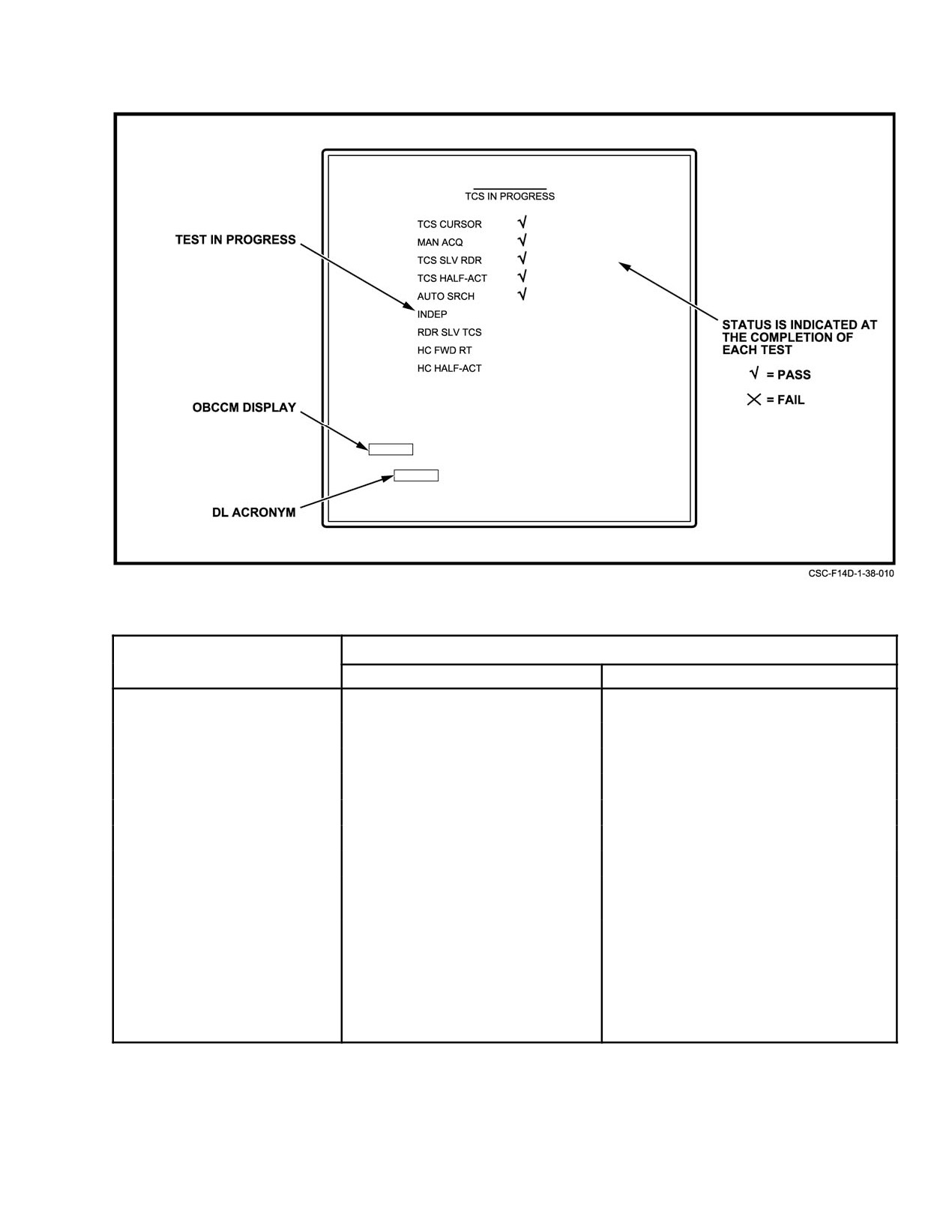
NAVAIR 01−F14AAD−1
Figure 38Ć37.ĄPTID Menu for TCS IBIT, In Progress
PROMPT
RIO RESPONSE
DISPLAY ON PTID
UNIT
ACTION
TCS CURSOR
Sensor hand control
Select TGS cursor
MAN ACQ
Digital display
Depress TCS MAN pushtile
TCS SLV RDR
Sensor slaving panel
Select TCS slave
TCS HALF−ACT
Sensor hand control
Select half action and release
AUTO SRCH
Digital display
Depress TCS ASCH pushtile
INDEP
Sensor slaving panel
Select TCS IND
RDR SLV TCS
Sensor slaving panel
Select RDR slave
HC FWD RT
Sensor hand control
Position hand control to upper right
corner
HC HALF−ACT
Sensor hand control
Select half action, maintaining HCN
in upper right corner
Figure 38Ć38.ĄTCS BIT Prompts and RIO Responses
38−61
ORIGINAL

NAVAIR 01−F14AAD−1
Figure 38Ć39.ĄInitial C/D TEST Display
Figure 38Ć40.ĄC/D TEST 1 Display (After Aging Is Completed)
ORIGINAL
38−62
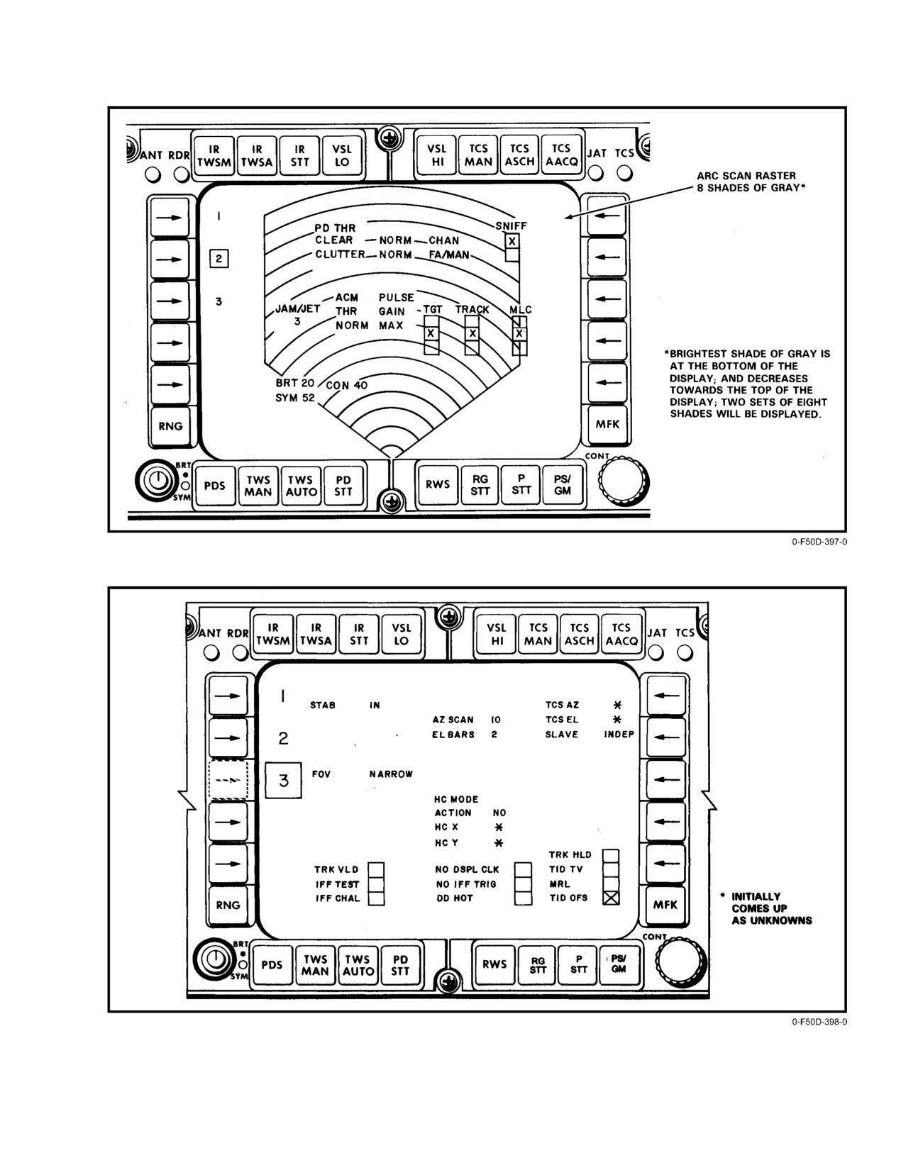
NAVAIR 01−F14AAD−1
Figure 38Ć41.ĄC/D TEST 2 Display
Figure 38Ć42.ĄC/D TEST 3 Display
38−63
ORIGINAL
NAVAIR 01−F14AAD−1
SCU CONTROL/SELECTION
DD RESPONSE
SHC CONTROL/SELECTION
DD RESPONSE
STAB/IN
IN
HC MODE/IR/TV
IR/TV
STAB/OUT
OUT
HC MODE/RDR
RDR
FOV/WIDE
WIDE
HC MODE/PTID CURSOR
PTID CURSOR
FOV/NAR
NARROW
HC MODE/DD CURSOR
DD CURSOR
TCS TRIM/AZ
−22 to +22
HANDGRIP ACTION SWITCH/
NO
TCS TRIM/EL
−44 to +44
(NO DETENT)
AZ SCAN/±10°
10
HANDGRIP ACTION SWITCH/
HALF
(FIRST DETENT)
AZ SCAN/±20_
20
HANDGRIP ACTION SWITCH/
FULL
AZ SCAN/±40_
40
(FULL DETENT)
AZ SCAN/±65_
65
HCX (HANDGRIP)
−99 to + 99
EL BARS/1
1
LEFT/RIGHT
EL BARS/2
2
HCY (HANDGRIP) FORE/AFT
−99 to + 99
EL BARS/4
4
MRL
X
EL BARS/8
8
OFFSET
X
SSP CONTROL/SELECTION
DD RESPONSE
SLAVE/RDR
RDR
SLAV/INDEP
INDEP
SLAVE/TCS
TCS
DD CONTROL/SELECTION
DD RESPONSE
ACQ/AUTO SRCH
AUTO SEARCH
Figure 38Ć44.ĄDD Responses for SHC Select Tests
ACQ/MAN
MANUAL
ACQ/AUTO
AUTO
VSL/HI
HI
PTID CONTROL/SELECTION
DD RESPONSE
VSL/OFF
OFF
TRACK HOLD
X
VSL/LO
LO
PTID MODE/TV
C
Figure 38Ć43.ĄDD Responses for SCU/SSP/DD
Figure 38Ć45.ĄDD Responses for PTID Select Tests
Select Tests
ORIGINAL
38−64
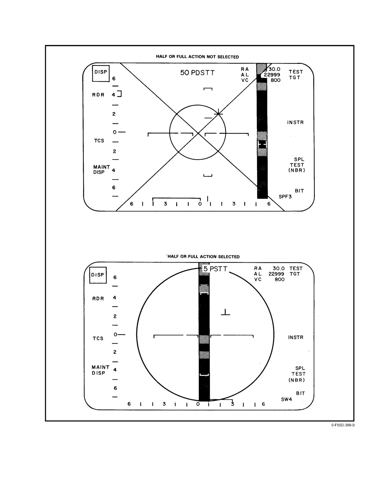
NAVAIR 01−F14AAD−1
Figure 38Ć46.ĄBIT Static DD Display (ATTK Selected)
38−65
ORIGINAL
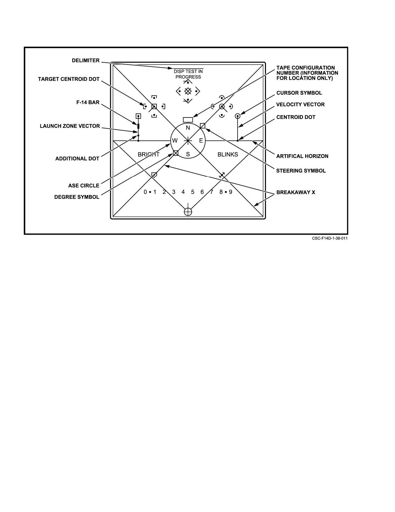
NAVAIR 01−F14AAD−1
Figure 38Ć47.ĄBIT Static PTID Display (ATTK Selected)
These test patterns should be examined by the RIO for
initial point symbol is displayed for reference. To enter the
the absence of any required symbols, symbol intensity, and
dynamic test, the RIO selects CLEAR, NBR, 1, 1, and ENT
symbol position. During the running of the static test, the RIO
on the DD keypad.
should also select half action or full action on the hand
When the RIO selects ATTK with the PTID MODE
control. The RIO should ensure that the PTID cursor can be
switch, the displays on the PTID and DD (Figure 38−40 and
moved throughout the range of the PTID by moving the hand
Figure 38−41) will go through the following movements
control. Upon release of the action switch, the cursor symbols
every 2 seconds:
should return to their original positions.
On the DD, the following occur simultaneously:
The static portion of the displays test gives the RIO an
indication that the computer does or does not have the display
1. The artificial horizon steps in pitch from zero to
capability for each of the indicated symbols. It is more than
+15° (up), +30_, +45_, 0_, −15_ (down), −30_, −45_,
a displays test because it also tests computer ability to
then back to 0°.
generate symbols needed for a tactical situation. The
computer assists the RIO in the static portion of the displays
2. The artificial horizon steps in roll from 0_ to +15_
test by monitoring power failures that have occurred in the
(right wing down), +30°, +45°, back to 0_, −15° (left
controls and displays units. A DISP FAILED indicator will
wing down), −30°, −45°, and back to 0°.
appear on the maintenance display if a power failure is
detected. The maintenance display indicates DISP PASSED
3. The ASE circle steps from 0.8 inch in diameter to
until a failure occurs.
0.1, 0.3, 0.56, then back to 0.8.
b. Dynamic Testing. The dynamic test consists of a visual
4. The steering symbol steps around the ASE circle in
evaluation of the movement of the artificial horizon, ASE
a clockwise direction in steps from its position in the
circle, steering symbol, closing range rate indicator, launch
upper right quadrant to the lower right, lower left,
zone symbols, and a velocity vector with TUIR and TUOR
upper left, then back to the upper right quadrant.
markers that sequentially vary in size or position. A fixed
ORIGINAL
38−66
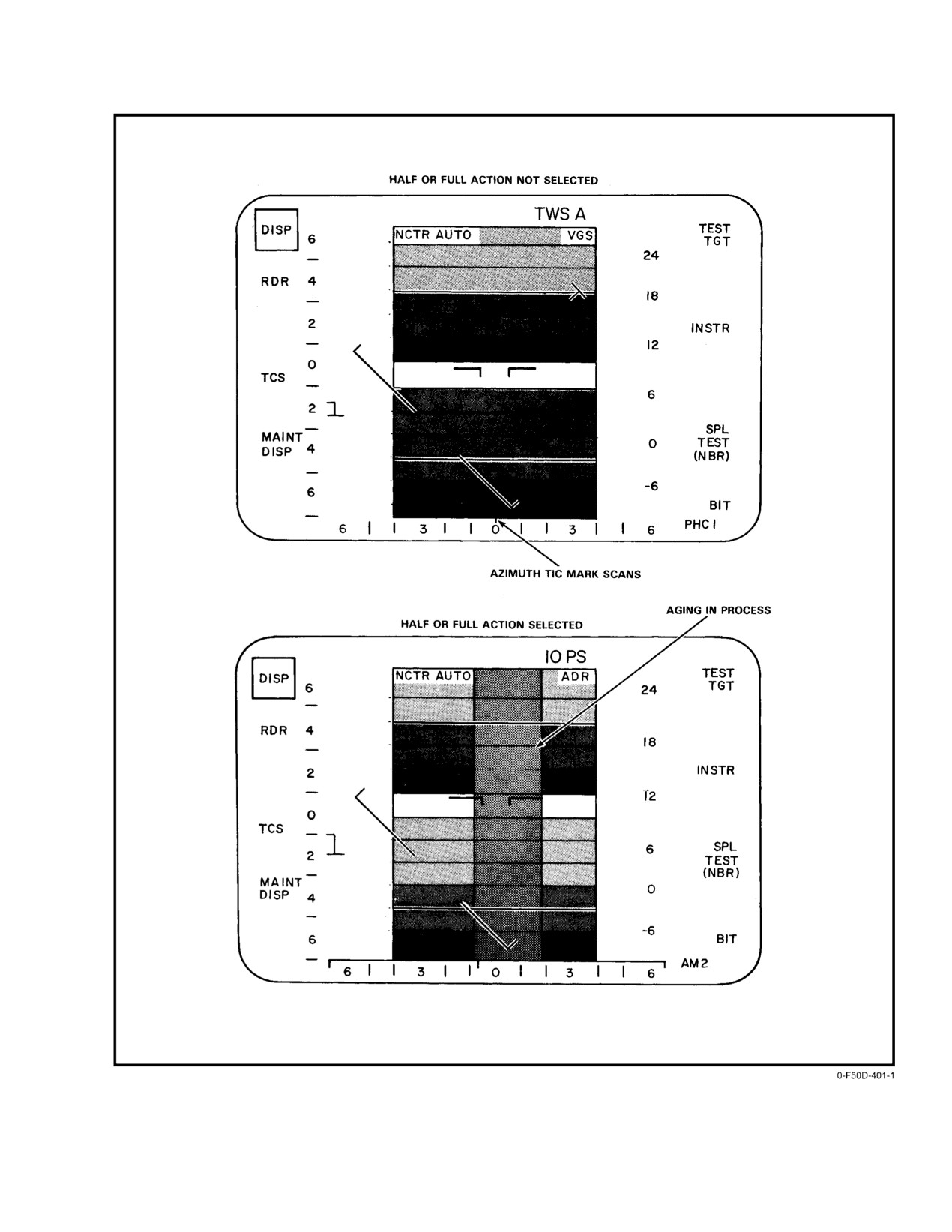
NAVAIR 01−F14AAD−1
Figure 38Ć48.ĄBIT Static DD Display (GND STAB or TV Selected)(Sheet 1 of 2)
38−67
ORIGINAL
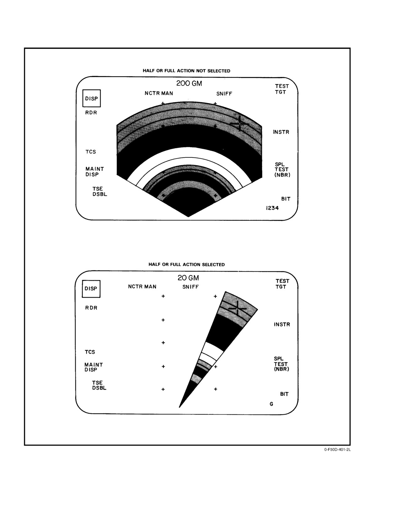
NAVAIR 01−F14AAD−1
Figure 38−48. BIT Static DD Display (GND STAB or TV Selected)(Sheet 2 of 2)
ORIGINAL
38−68
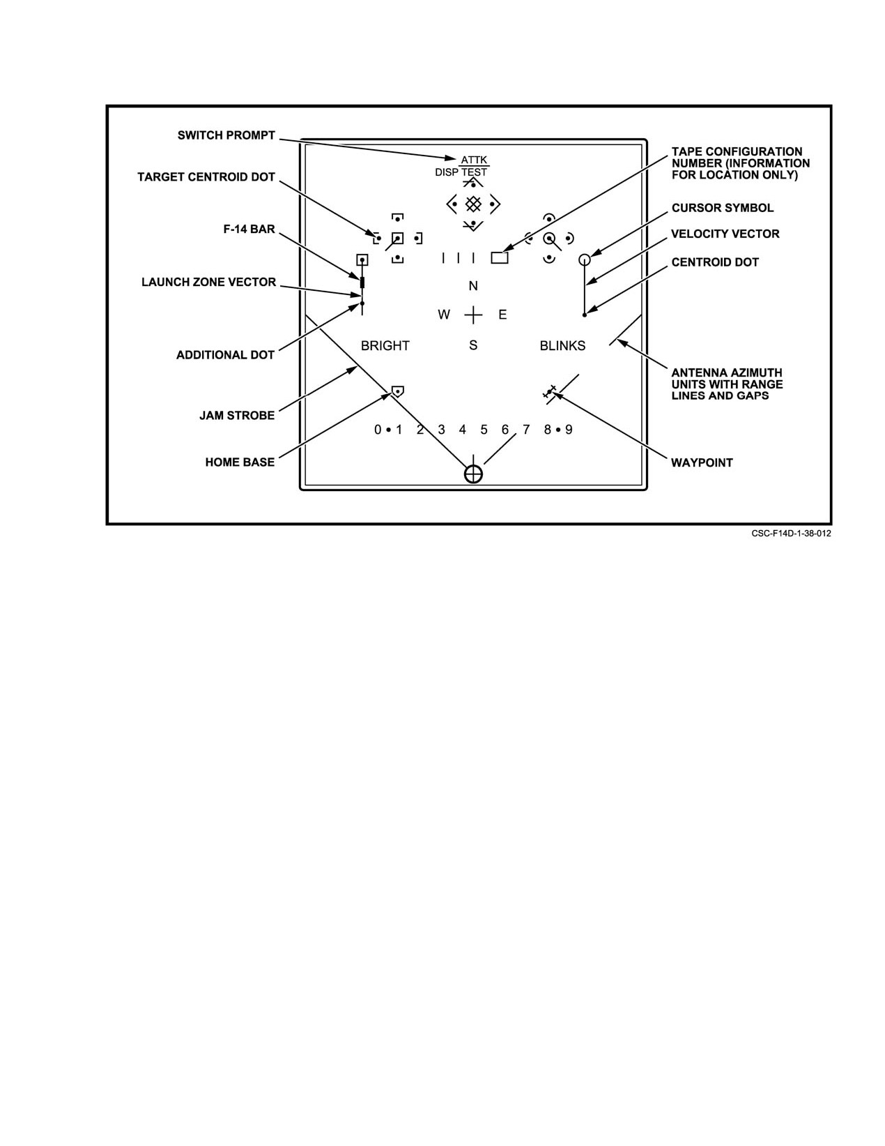
NAVAIR 01−F14AAD−1
Figure 38Ć49.ĄBIT Static PTID Display (Non−ATTK Selection)
On the PTID, the following occur simultaneously:
7. The velocity vector will vary in length from 1.5
inches to 0 inches, 0.5 inches, 1.0 inches, then back
1. The artificial horizon steps in pitch from zero to
to 1.5 inches.
+15° (up), +30°, +45°, 0°, −15° (down), −30_, −45_
then back to 0°.
8. The F−14 bar origin will vary its distance above the
artificial horizon along the velocity vector from 1.5
2. The artificial horizon steps in roll from 0_ to +15°
inches to 1.0 inches, 0.5 inches, 0 inches, then back
(right wing down), +30°, +45_, back to 0_, −15° (left
to 1.5 inches.
wing down), −30_, −45°, and back to 0_.
9. The additional dot marker will vary its distance
3. The bar marker steps from 1.5 inches above the artiĆ
above the artificial horizon along the velocity
ficial horizon to 1.0, 0.5, 0, and back to 1.5 inches.
vector from 0 to 0.5 inch, 1.0 inch, 1.5 inches, then
back to 0 inches.
4. The dot marker steps from above the artificial to 0.5,
The events occurring during the dynamic portion of the
1.0, 1.5 inches and back to the artificial horizon.
test are repeated until the RIO selects another BIT sequence
5. The artificial horizon, ASE, and steering symbol
test, selects another category, interrupts via a program restart,
move on the PTID at the same rate as the DD.
or selects another radar mode.
When the RIO selects A/C STAB or GND STAB with
6. The ASE circle steps from 2.0 inches in diameter to
the PTID MODE switch, the displays on the PTID and DD
0.2, 0.8, 1.4, then back to 2.0 inches in diameter.
will go through the following movements every 2 seconds.
38−69
ORIGINAL
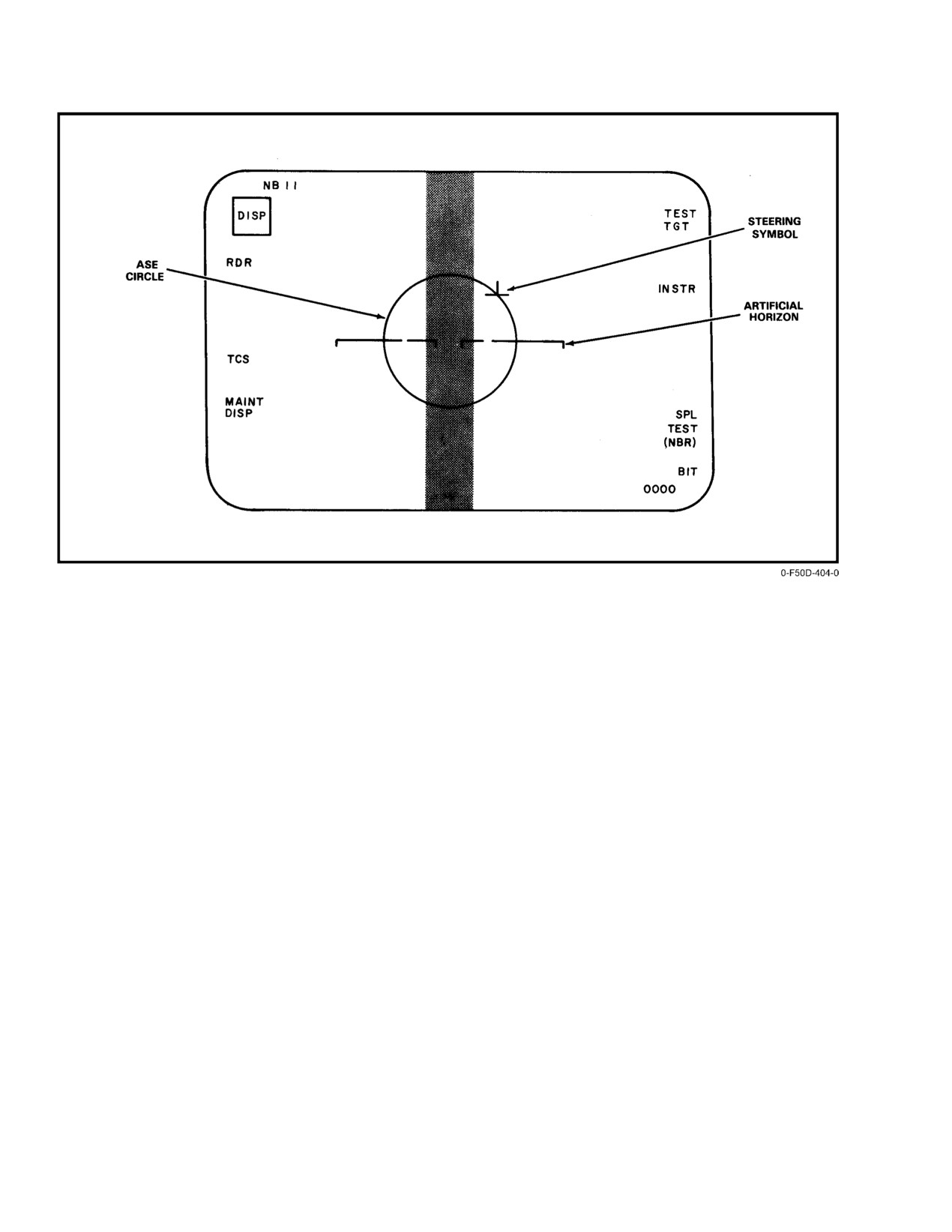
NAVAIR 01−F14AAD−1
Figure 38Ć50.ĄBIT DD Dynamic Display
Dynamic test in A/C STAB and GND STAB will have
When commanded by this function, instrumentation modĆ
displays similar to those shown in Figures 38−50 and 38−51,
ules in the RDP and RSP are configured to output repeatable
except that ATTK will blink above the BIT horizontal
test patterns to the instrumentation recorders. Failure indicaĆ
boundary, and the artificial horizon, ASE circle, and steering
tions are determined by analysis of these recordings offline.
symbol will be deleted. A DISP FAILED message will appear
The display is shown in Figure 38−52.
on the PTID during the static or dynamic tests when a fault
is detected. A fault isolation display can be requested by
38.5.3
Flycatcher
depressing the pushtile adjacent to MAINT DISP on the DD
Flycatcher is a computer routine that allows the
BIT menu. If a power fault or computer subsystem fault was
operator to examine the contents of specific RDP memory
detected, the unit designator of the malfunctioned WRA is
locations. This information is generally used in troubleĆ
displayed along with the associated DPs on the PTID.
shooting. Flycatcher readouts will be displayed on the upper
left portion of the DD. The display will consist of the
38.5.2.1.10
Special Test Format
computer designation readout, address readout and data
Special test is initiated via the selection of the SPL
readout (in hexadecimal).
TEST pushtile on the BIT menu, selection of the NBR
To initiate these readouts, the following sequence of
pushtile on the DD keypad, entering the appropriate test
entries on the CAP portion of the DD must be used:
number, and then pushing the ENT pushtile. Test execution
is continual while special test is selected. Testing is
1. CLR.
interruptible by a program restart (by depressing PGM RST
on the DD), another BIT selection, or radar mode selection.
2.
7.
The special test 80−instrumentation test verifies the
3.
1.
proper operation of the APG−71 instrumentation system. This
system includes the IST and ICU modules within the RDP
4. ENT.
and RSP, respectively, and the interface to the data recorder.
ORIGINAL
38−70
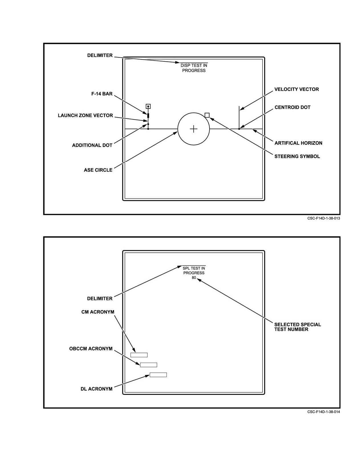
NAVAIR 01−F14AAD−1
Figure 38Ć51.ĄBIT Dynamic PTID Display (ATTK Selected)
Figure 38Ć52.ĄSpecial Test 80−Instrumentation Test
38−71
ORIGINAL
NAVAIR 01−F14AAD−1
A computer number of 1 selects the RDP memory,
To decrement the displayed address, the following
currently the only valid selection. Next, a hexadecimal
sequence must be entered:
memory address must be entered in the following sequence:
1. CLR.
1. 9.
2.
7.
2. 0.
3. S−W.
3. 1 to 5−digit hex address.
4. ENT.
4. ENT.
If an increment is performed, and no further CAP
The flycatcher has the capability to increment or
selections have been made, subsequent increments or
decrement the displayed address. To increment the displayed
decrements can be made by simply pressing the ENT pushtile
address, the following sequence must be entered:
repeatedly.
The flycatcher is turned off with the following CAP
1. CLR.
sequence:
2. 7.
1. CLR.
3. N+E.
2.
7.
4. ENT.
3.
0.
4. ENT.
ORIGINAL
38−72
NAVAIR 01−F14AAD−1
PART X
NATOPS Evaluation
Chapter 39 NATOPS Evaluation and Question Bank
93 (Reverse Blank)
ORIGINAL
NAVAIR 01−F14AAD−1
CHAPTER 39
NATOPS Evaluation
39.1
NATOPS EVALUATION PROGRAM
39.1.3
Definitions
The following terms, used throughout this chapter, are
39.1.1
Concept
defined below as to their specific meaning within the
NATOPS program.
The standard operating procedures prescribed in this
manual represent the optimum method of operating the airĆ
39.1.3.1
NATOPS Evaluation
craft. The NATOPS evaluation is intended to evaluate comĆ
pliance with NATOPS procedures by observing and grading
A periodic evaluation of individual flightcrewmemĆ
individuals and units. This evaluation is tailored for compatiĆ
bers standardization consisting of an open−book examinaĆ
bility with various operational commitments and missions of
tion, closed−book examination, oral examination, and flight
both Navy and Marine Corps units. The prime objective of
evaluation.
the NATOPS evaluation program is to assist the unit comĆ
39.1.3.2
NATOPS Reevaluation
manding officer in improving unit readiness and safety
through constructive comment. Maximum benefit from the
A partial NATOPS evaluation administered to a
NATOPS program is achieved only through the vigorous
flightcrewmember who has been placed in an Unqualified
support of the program by commanding officers as well as by
status by receiving an Unqualified grade for any ground
flightcrewmembers.
examination or for the flight evaluations. Only those areas in
which an unsatisfactory level was identified need be
39.1.2
Implementation
observed during a reevaluation.
The NATOPS evaluation program shall be carried out
39.1.3.3
Qualified
in every unit operating naval aircraft. The various categories
The evaluation term applied to a flightcrewmember
of flightcrewmembers desiring to attain and retain qualificaĆ
who is well standardized and who demonstrates highly
tion in the F−14D shall be evaluated initially in accordance
professional knowledge of and compliance with NATOPS
with the current OPNAV Instruction 3710, and at least once
standards and procedures. Momentary deviations from or
during the 12 months following initial and subsequent evaluĆ
minor omission in noncritical areas are permitted if prompt
ations. Individual and unit NATOPS evaluations will be conĆ
and timely remedial action was initiated by the evaluee.
ducted annually; however, instruction in and observation of
adherence to NATOPS procedures must be on a daily basis
39.1.3.4
Conditionally Qualified
within each unit to obtain maximum benefits from the proĆ
gram. The NATOPS coordinators, evaluators, and instructors
The evaluation term applied to a flightcrewmember
shall administer the program as outlined in the current
who is satisfactorily standardized, who may have made one
OPNAVINST 3710. Evaluees who receive a grade of
or more significant deviations from NATOPS standards and
Unqualified on a ground or flight evaluation shall be allowed
procedures but made no errors in critical areas and no errors
30 days in which to complete a reevaluation. A maximum of
jeopardizing mission accomplishment or flight safety.
60 days may elapse between the date of the initial ground and
flight evaluation and the date that qualification is satisfactoĆ
39.1.3.5
Unqualified
rily completed. F−14A/B NATOPS evaluations can be
The evaluation term applied to a flightcrewmember who
accomplished during the same evaluation flight provided the
is not acceptably standardized, who failed to meet minimum
currency requirements for each model established in Chapter
standards regarding knowledge of and/or ability to apply
5 are met. The results will be recorded on the NATOPS evaluĆ
NATOPS procedures, or who made one or more significant
ation report (OPNAV Form 3710/7).
deviations from NATOPS standards and procedures that could
jeopardize mission accomplishment or flight safety.
39−1
ORIGINAL