MANUAL OF NATO SAFETY PRINCIPLES FOR THE STORAGE OF MILITARY AMMUNITION AND EXPLOSIVES (May 2010) - page 18

NATO/PFP UNCLASSIFIED
AASTP-1
(Edition 1)
Equivalent cover thickness = 1.0 Q1/3
Solution: From Table 1-II and 1-III, A = 1.54, m = 1.71, B = 51, n = 0.67
1
1
1
−
m
3
−
1.71
IBD = (
)
*(Q
) = (
)
*(125,0003)1
= 110 metres
A
1.54
R
−n
110
−0.67
Check PF = B(
1
/
3
)
= 51(
1/3
)
= 31 Hz > 30 Hz => Ok!
Q
125,000
4
Ground Shock IBD for non-RC Structures
For non-RC structures, the allowable ground shock peak particle velocity PPVa
criteria are given according to their foundation geology as follows:
Foundation on Soil : PPV = 60 - 200 mm/s
(Sand, gravel, clay)
Foundation on Soft Rock : PPV = 115 - 400 mm/s
(Firm moraine slate, shale stone, soft limestone)
Foundation on Hard Rock
: PPV = 230 - 800 mm/s
(Granite, gneiss, diabase, quartzite sandstone, hard limestone)
Based on the selected allowable PPVa value, the ground shock IBD for non-RC
structures can be calculated as follows.
1
1
PPV
−
a
m
3
IBD = (
)
(Q
)
A
Where IBD = Inhabited Building Distance in metres, measured directly from the
chamber wall. The ground shock parameters, A and m, can be referred from Table
1-II based on the geological classification in Table
1-I, and the cavern design
parameters.
Example #1:
Given: Q = 125,000 kg
Loading density = 10 kg/m3
Span-length ratio = 1:4
Foundation on Hard Rock
Geology: Good Rock
Equivalent cover thickness = 1.0 Q1/3
Solution: From Table 1-II, A = 0.75, m = 1.23
Chosen PPVa at IBD = 0.23 m/s
−
1
1
−
1
PPV
a
m
3
0.23
1.23
IBD = (
)
*(Q
)= (
)
*(125,0003)1
= 131 metres
A
0.75
NATO/PFP UNCLASSIFIED
-III-3-52-
Change 3

NATO/PFP UNCLASSIFIED
AASTP-1
(Edition 1)
Example #2:
Given: Q = 125,000 kg
Loading density = 10kg/m3 Span-length ratio = 1:4
Foundation on Soil
Geology: Mixed media with Good Rock
Equivalent cover thickness = 1.0 Q1/3
Solution: From Table 1-II,
A = 1.29, m = 1.71
Chosen PPVa at IBD = 0.06 m/s
−
1
1
−
1
PPV
a
m
3
0.06
1.71
IBD = (
)
*(Q
)= (
)
*(125,0003)1= 301 metres
A
1.29
5
Validity of Range
The range of validity for the IBD equations proposed in the following cover charge
weights up to 500 tonnes, chambers of length ranging from 45 to 120 m with
maximum volume of 50,000 m3, and span to length ratio between 1:2 and 1:4. The
loading densities considered range up to 50 kg/m3 with rock cover or equivalent
cover about 1.0Q1/3 m. Interpolations can be carried out between the recommended
values for different storage conditions.
The ground shock IBD given in this chapter is for a typical reinforced concrete
structure up to ten storeys, with span up to 5 m and inter-height up to 3 m. Little work
has been done to quantify the damage criteria for other structure types of masonry,
wooden and steel. A specific analysis should be conducted and siting decisions
should be based on the foundation type and robustness of these structures to
withstand the ground shock.
For storage sites where the rock cover or equivalent cover is less than 1.0Q1/3, the
equations given by Table 1-II and Table 1-III should not be used to predict the
ground shock parameters for scaled range less than 1 m/kg1/3. For cases where the
rock cover or equivalent cover is significantly more than 1.0Q1/3, Table 1-II may
under-predict the peak particle velocities on the ground surface.
For storage sites that deviate very much from the conditions specified, further study
and analysis is recommended and detailed site specific characterisations should be
used to support the final construction and explosives safety siting decisions.
Other Hazard Divisions
For HD 1.2, a single item (or that explosives weight for the maximum number of
items to react simultaneously) can be treated as HD 1.1 for the purpose of ground
shock prediction. Otherwise, ground shock effects from HD 1.2 in bulk storage are
negligible.
NATO/PFP UNCLASSIFIED
-III-3-53-
Change 3

NATO/PFP UNCLASSIFIED
AASTP-1
(Edition 1)
For HD 1.3 stored in underground caverns, it should be treated as HD 1.1 for the
purpose of ground shock prediction.
The ground shock effects resulting from HD 1.4 items can be neglected.
For HD 1.2, 1.3, and 1.4 items or storage where various HD’s are mixed, it is safe
and conservative to treat all items as HD 1.1 for the purpose of ground shock
prediction.
NATO/PFP UNCLASSIFIED
-III-3-54-
Change 3

NATO/PFP UNCLASSIFIED
AASTP-1
(Edition 1)
Table 1-I: Classification of Site Geology for Ground Shock Analysis
Typical Rock
Gabbro, Gneiss,
Mudstone, Siltstone,
Tuff, Chalk, Rock
Type
Granite, Norite,
Shale, Slate,
Salt, Coal,
Andesite, Dolerite,
Limestone*,
Limestone*,
Diabase, Rhyolite,
Sandstone*
Sandstone*
Quartzite, Dolomite,
Rock Mass
Marble, Limestone*,
Quality
Sandstone*
Good to Very good
quality rock mass with
few sets of unweathered
or slightly weathered
discontinuity sets
Good
Fair
Poor
Q > 10
RMR > 65
RQD > 75%
Vp > 4500 m/s
Fair to good quality rock
mass with several sets of
moderately weathered
discontinuities
1 < Q < 10
Fair
Fair
Poor
50 < RMR < 65
50% < RQD < 75%
3500 < Vp < 4500 m/s
Poor quality rock mass
with
numerous
weathered joints
Q < 1
Poor
Poor
Poor
RMR < 50
RQD < 50%
Vp < 3500 m/s
where
RMR = Rock Mass Rating
RQD
= Rock Quality Designation
Q
= Rock Quality Index
NATO/PFP UNCLASSIFIED
-III-3-55-
Change 3
NATO/PFP UNCLASSIFIED
AASTP-1
(Edition 1)
Table 1-II: Summary of Initial Value, A and attenuation coefficient, m for
Peak Particle Velocity (PPV) Prediction Equation
A. For PPV in Single Medium Geology
A.1 Chamber with width-to-length ratio of 1:2
Loading Density, kg/m3
Geology
5
10
20
50
A
m
Good Rock
0.79
1.08
1.35
1.52
1.23
Fair Rock
1.00
1.19
1.40
1.62
1.56
Poor Rock
1.00
1.30
1.55
1.82
1.90
A.2 Chamber with width-to-length ratio of 1:4
Loading Density, kg/m3
Geology
5
10
20
50
A
m
Good Rock
0.56
0.75
1.08
1.20
1.23
Fair Rock
0.78
1.00
1.23
1.49
1.56
Poor Rock
0.78
1.01
1.39
1.64
1.90
B. For PPV in Mixed-Media Geology
B.1 Chamber with width-to-length ratio of 1:2
Loading Density, kg/m3
Geology
5
10
20
50
A
m
Good Rock
1.14
1.38
1.54
1.77
1.71
Fair Rock
1.41
1.69
2.01
2.37
2.01
Poor Rock
1.89
2.32
2.60
2.96
2.34
B.2 Chamber with width-to-length ratio of 1:4
Loading Density, kg/m3
Geology
5
10
20
50
A
m
Good Rock
1.08
1.29
1.45
1.70
1.71
Fair Rock
1.20
1.62
1.85
2.13
2.01
Poor Rock
1.78
2.10
2.47
2.77
2.34
Note:
Peak Particle Velocity, PPV = A (R/Q1/3)-m
NATO/PFP UNCLASSIFIED
-III-3-56-
Change 3
NATO/PFP UNCLASSIFIED
AASTP-1
(Edition 1)
Table 1-III: Summary of initial value, B and attenuation coefficient, n for
Principal Frequency (PF) Prediction Equation
Loading Density, kg/m3
Geology
and
Chamber
5
10
20
50
Geometry
B, Hz
n
Single Medium Geology
Chamber with width-to-length
85
76
72
65
ratio of 1:2
0.84
Chamber with width-to-length
96
86
79
73
ratio of 1:4
Mixed Media Geology
Loading Density, kg/m3
5
10
20
50
B, Hz
n
Chamber with width-to-length
64
61
51
45
0.67
ratio between 1:2 and 1:4
Note:
Principal Frequency, PF = B (R/Q1/3)-n
Table 2-I: Classification of Building Damage
Damage
Damage
Description of Damage - High
State of Building
Index
Frequency Response
Minor
< 0.4
Small cracks in concrete.
Easily repairable
Reinforcement still in elastic
state. Overall stiffness reduction
by about 20-40%.
Moderate
0.4
- 0.6
Many small cracks occur along
Repairable
structural members. Overall
stiffness reduction by about 40-
60%
Severe
0.6
- 0.9
Many large cracks, some areas
Non-repairable
with plastic hinge formation,
reinforcement yields. Overall
stiffness reduction by 60-100%.
Collapse
> 0.9
Collapse. Complete loss of
Loss of building
stiffness.
NATO/PFP UNCLASSIFIED
-III-3-57-
Change 3

NATO/PFP UNCLASSIFIED
AASTP-1
(Edition 1)
Section V - Public Traffic Route Distances (PTRD)
Public traffic route distance (PTRD) (For all Hazard divisions)
1. Ground Shock QD is 2/3 of IBD for ground shock.
2. Debris QD is 2/3 of IBD for debris.
3. The calculated distance according to equation
3.3.4-5 should be used,
alternatively the more conservative 2/3 of IBD could be used..
4. For heavy traffic use the maximum IBD determined in the previous three
paragraphs.
5. Because of the hazards arising from the strong on-axis jetting, special
considerations should be given when ES is on the extended centreline of the
main passageway.
NATO/PFP UNCLASSIFIED
-III-3-58-
Change 3

NATO/PFP UNCLASSIFIED
AASTP-1
(Edition 1)
Section VI - Explosives Workshop Distance (EWD)
An Explosives Workshop (EW) may be either an aboveground structure or an
underground chamber with its own entrance tunnel. Except for HD
1.4
ammunition, an underground EW should not be connected
(air ducts,
passageways, etc.) to other underground storage chambers. Otherwise, an
underground ES should be sited as a storage chamber. Distances between
PES and EW are intended to provide a reasonable degree of personnel
protection within the EW from the effects of a nearby explosion (blast, flame,
debris, and ground shock).
An explosion in an underground facility produces a directional impulsive load
along the extended centerline axis of an adit. This impulsive load is
considerably more intense at a given distance than that from a comparable
above ground detonation. Little work has been done to quantify the on-axis
impulsive load as a function of distance.
3.3.6.1. Potential Crater
An Aboveground EW should be sited so it is at least outside the potential
crater of an underground explosion.
3.3.6.2. Aboveground EW Located within the Maximum Dispersal Angle
An unhardened EW should be sited at the corresponding IBD found above.
3.3.6.3. Aboveground EW Located Outside the Maximum Angle of Dispersal
An EW may be sited at 1/3 of the corresponding IBD found above. Required
distance from the tunnel adit because of airblast could be determined from
Eq. 3.3.4-6.
NATO/PFP UNCLASSIFIED
-III-3-59-
Change 3

NATO/PFP UNCLASSIFIED
AASTP-1
(Edition 1)
Section VII - Aboveground Earth-Covered Magazine (ECM)
A site-specific analysis should be conducted and siting decisions should be
based on the protection the ECM provides.
NATO/PFP UNCLASSIFIED
-III-3-60-
Change 3

NATO/PFP UNCLASSIFIED
AASTP-1
(Edition 1)
Section VIII - Aboveground Magazine Distance (AGMD)
An unbarricaded AGM should be sited at 2/3 of the corresponding IBD found
above.
A barricaded AGM should be sited at 1/3 of the corresponding IBD found
above.
NATO/PFP UNCLASSIFIED
-III-3-61-
Change 3

NATO/PFP UNCLASSIFIED
ANNEX III-A
AASTP-1
(Edition 1)
REFERENCES
UNDERGROUND STORAGE
EXPLOSIVES SAFETY HAZARDS
NATO/PFP UNCLASSIFIED
-III-A-1-
Change 3

NATO/PFP UNCLASSIFIED
Releasable to Mediterranean Dialogue Nations
[1]
AASTP-1,
“Manual of NATO Safety Principles for the Storage of Military
Ammunition and Explosives” (May 1992)
[2]
Wilfred E. Baker, Peter S. Westine, and Franklin P. Dodge, “Similarity Methods in
Engineering Dynamics, Theory and Practice of Scale Modeling”, Published by
Elsevier (1991)
[3]
LLNL Explosives Handbook, “Properties of Chemical Explosives and Explosive
Simulants, Change 2, “Lawrence Livermore National Lab., CA.; Department of
Energy, Washington, DC. (NTIS Order Number: DE91006884INZ)
[4]
Swiss Federal Buildings Office/Engineering Division - Swiss-Klotz Design, Drawing
Nos. 1036.SP.2.020/025/027
[5]
US Army Corps of Engineers Drawings, "Definitive Drawings Underground
Storage Facility" (DEF 421-80-04)
[6]
Royal Swedish Fortifications Administration - Klotz-Test Operation Block, Report
No. 119:5, 01.05.1974
[7]
L. K. Davis and So-Young Song,
“Technical Managers Final Report,” Joint
U.S./ROK R&D Program for New Underground Ammunition Storage Technologies
TR SL-97-10 and UAST-TR-97-002 (September 1997)
[8]
NO(ST)(UGS/AHWP)IWP 6-98 dated 24 November 1998 One-dimensional Blast
Wave Propagation
[9]
NO(ST)(UGS/AHWP) IWP 8-98 dated
24 November
1998 Model Tests of
Accidental Explosions in Underground Ammunition Storage, II: Blast Wave
Propagation in Tunnel Systems
[10] NO(ST)(UGS/AHWP) IWP
7-98 dated
24 November
1998 Model Test of
Accidental Explosions in Underground Ammunition Storage, I: Chamber Pressure
[11] NO(ST)(UGS/AHWP) IWP 9-98 dated 24 November 1998 Blast Propagation
outside a Typical Underground Storage Site
[12] NO(ST)(UGS/AHWP) IWP
10-98 dated
24 November
1998 Underground
Ammunition Storage Magazines, Blast Effects from Accidental Explosions.
(Norwegian Magazines Standard)
[13] NO(ST)(UGS/AHWP) IWP 11-98 dated 24 November 1998 Calculation of Airblast
from Underground Ammunition Storage Magazines.
(Norwegian Magazines
Standard)
NATO/PFP UNCLASSIFIED
Change 3

NATO/PFP UNCLASSIFIED
ANNEX III-A
AASTP-1
(Edition 1)
[14] NO(ST)(UGS/AHWP) IWP 12-98 dated 24 November 1998 Air Blast from Tubes
Meeting 27-28 October 1987
[15] NO(ST)(UGS/AHWP) IWP
13-98 dated
24 November
1998 Underground
Ammunition Storage. Blast Effects from Accidental Explosions
[16] UK(ST)IWP 311 dated 3 March 1998 - AASTP- I Advice on Adit Debris Projections
from Underground Storage Sites
[17] CH(ST)UGS/AHWP IWP 007 dated 30 October 1998 - Debris Throw from Adit
Tunnels. Proposed Changes to the NATO Safety Manual AASTP- 1, Part III
Technical Background for Throw Distances
[18] CH(ST)UGS/AHWP IWP 005 dated 30 May 1998 - Debris Throw from Craters -
Proposed Changes to the NATO Safety Manual AASTP-1, Part III - Technical
Background
[19] CH(ST) UGS/AHWP IWP 006 dated 30 October 1998 - Debris Throw from
Craters - Proposal Changes to the NATO Safety Manual AASTP-1, Part III -
Proposed Wording
[20] CH(ST)UGS/AHWP IWP 008 dated 4 November 1998 - Proposed Changes to the
NATO Safety Manual AASTP- 1, Part III - Proposed Wording - Swiss Contribution
[21] CH(ST)UG/AHWP IWP 002 dated 24 September 1997 - Debris Throw from
Craters. - Pertinent Technical Reports
[22] CH(ST)UG/AHWP IWP 003 dated I October 1997. - Debris Throw from Craters.
[23] US MEMO, dated 30 July 1997 - Recommendations for Ground Shock Criteria in
NATO Documents
[24] US(ST)(UGS/AHWP) IWP 1-98 dated 30 September 1998 - US proposal for
Ground Shock from an Underground Storage Facility
[25] US MEMO, dated 31 December 1997 - Proposal for Ground Shock Explosives
Safety Principles
[26] NO(ST)UGS/AHWP IWP 1/98 dated 11 February 1998 - AASTP- I Part II,
Inhabited Building Distance, Ground Shock
NATO/PFP UNCLASSIFIED
-III-A-3-
Change 3

NATO/PFP UNCLASSIFIED
ANNEX III-A
AASTP-1
(Edition 1)
[27] Fook-Hou Lee, Wee-Beng Koh, and Thiam-Soon Tan, "Numerical Back Analysis
of Field Measurements of Ground Vibration from Underground Explosions," 28th
DOD Explosives Safety Seminar 18-20 August 1998, Orlando, Florida
[28] Yingxin Zhou, Karen O Y Chong, and Yaokun Wu, "Small-Scale Testing on
Ground Shock Propagation in Mixed Geological Media," 28th DOD Explosives
Safety Seminar 18-20 August 1998, Orlando, Florida
[29] Yingxin Zhou, Hong Hao, and Guowei Ma, "Ground Shock Damage Criteria for
Inhabited Buildings," 28th DOD Explosives Safety Seminar 18-20 August 1998,
Orlando, Florida
[30] US(ST)(UGS/AHWP) IWP 1-98 dated 30 September 1998 - US proposal for
Ground Shock from an Underground Storage Facility
[31] NO(ST)(UGS/AHWP) IWP 14-98 dated 15 December 1998 - Ground Shock in
Rock-Full scale Tests in Norway
[32] US MEMO, dated 16 December 1998, Minutes of Special UGS/AHWP meeting
15-16 October 1998
[33] Peter Westine, "Ground Shock from the Detonation of Buried Explosives, "Journal
of Terramechanics, Vol 15, No 2, pp 69-79 (1978)
[34] CH(ST) UG/AHWP IWP 4 dated 6 March 1998 - Debris Throw from Craters - CH
Status Report as of 6 March 1998
[35] PFP(AC_326-SG_5)(CUSTODIAN-UGAS)(NO)IWP(2006)0001
[36] PFP(AC_326-SG_5)(CUSTODIAN-UGAS)(NO)IWP(2006)0002.
[37] NATO - Allied Ammunition Storage and Transport Publication (AASTP)
AASTP-4, "Explosives Safety Risk Analysis"
NATO AC/258 Risk Analysis Working Group (RAWG)
AC/258(ST)WP/214 / 27.02.2001 / NATO PFP unclassified
[38] Debris Throw from Adits of Underground Installations in Rock
Basics for Risk Analysis - Technical Background
Contribution to NATO - AC/258 Storage Sub Group - UGSWG
Defence Procurement Agency - General Staff, Switzerland
Bienz, Kummer & Partner AG
Kummer, P.; Willi, W.; Nussbaumer, P.
TM 174-9 // AC/258 CH(ST)IWP 024-02 / 30.03.2002
NATO/PFP UNCLASSIFIED
-III-A-4-
Change 3

NATO/PFP UNCLASSIFIED
ANNEX III-A
AASTP-1
(Edition 1)
[39] Trümmerwurf aus Zugangsstollen von Felsanlagen
TLM 75/Teil 2 - Revision technische Anhänge
Grundlagen
Generalstab - Sektion SUR
Bienz, Kummer & Partner AG
Kummer, P.; Willi, W.; Nussbaumer, P.
B 150-12 / 30.11.2001
[40] Debris Throw from Adit Tunnels
Proposed Changes to the NATO Safety Manual AASTP-1, Part III
Technical Background for Throw Distances
Contribution to NATO - AC/258 Underground Storage Ad hoc Working Party
Defence Procurement Agency, Switzerland
Bienz, Kummer & Partner AG
Kummer, P.
TM 158-9 // CH(ST)UGS/AHWP IWP 007 / 30.10.1998
[41] Debris Throw from Adit Tunnels
Proposed Changes to the NATO Safety Manual AASTP-1, Part III
Proposed Wording
Contribution to NATO - AC/258 Underground Storage Ad hoc Working Party
Defence Procurement Agency, Switzerland
Bienz, Kummer & Partner AG
Kummer, Peter
TM 158-10 // CH(ST)UGS/AHWP IWP 008 / 04.11.1998
[42] Debris Throw from Adits
Basics for Risk Analysis
Proposed Wording for AASTP-4
CH Contribution to the NATO AC/258 Storage Sub-Group - UGSWG
Defence Procurement Agency / General Staff - Switzerland
Bienz, Kummer & Partner AG
Nussbaumer, P.; Kummer, P.
AC/258 CH(ST)IWP 030-02 // TM 174-15 / 28.02.2002 / NATO PFP unclassified
NATO/PFP UNCLASSIFIED
-III-A-5-
Change 3

AASTP-1
(Edition 1)
ALLIED AMMUNITION STORAGE AND TRANSPORT PUBLICATION 1
(AASTP-1)
MANUAL OF NATO SAFETY PRINCIPLES
FOR THE STORAGE OF MILITARY
AMMUNITION AND EXPLOSIVES
PART IV
SPECIAL SITUATIONS
May 2010
IV-1
Change 3

AASTP-1
(Edition 1)
TABLE OF CONTENTS
CHAPTER 1 - GENERAL
IV-1-1
CHAPTER 2 - FIELD STORAGE
IV-2-1
SECTION I - INTRODUCTION
IV-2-1
SECTION II - FIELD STORAGE HISTORY
IV-2-3
SECTION III - DEFINITIONS
IV-2-8
SECTION IV - GUIDELINES FOR FIELD STORAGE
IV-2-9
SECTION V - FIREFIGHTING
IV-2-23
CHAPTER 3 - QUANTITY DISTANCE PRINCIPLES FOR MISSILE INSTALLATIONS
IV-3-1
CHAPTER 4 - reserved
IV-4-1
CHAPTER 5 - QUANTITY DISTANCE PRINCIPLES FOR AIRFIELDS USED ONLY BY MILITARY
AIRCRAFT
IV-5-1
CHAPTER 6 - SAFETY PRINCIPLES FOR THE TRANSFER OF MILITARY AMMUNTION AND
EXPLOSIVES IN NAVAL OR MILITARY PORTS
IV-6-1
SECTION I - INTRODUCTION
IV-6-1
SECTION II - GENERAL
IV-6-3
SECTION III - CALCULATION OF THE NET EXPLOSIVES QUANTITY
IV-6-4
SECTION IV - LEVELS OF PROTECTION AGAINST PROPOGATION FOR HD 1.1
IV-6-7
SECTION V - PROTECTION BETWEEN VESSELS EACH LOADED WITH MILITARY EXPLOSIVES
............................................................................................................................................................................. IV-6-8
SECTION VI - PROTECTION FROM VESSELS LOADING OR UNLOADING MILITARY
EXPLOSIVES
IV-6-10
SECTION VII - SCUTTLING AREAS
IV-6-14
ANNEX IV-A - QD TABLES FOR VESSELS
IV-6-15
ANNEX IV-B - SUMMARY OF QUANTITY-DISTANCES TO BE OBSERVED FOR SEAGOING
VESSELS LOADED WITH OR LOADING OR UNLOADING MILITARY EXPLOSIVES HD 1.1 IN
NAVAL PORTS
IV-6-16
IV-2
Change 3

AASTP-1
(Edition 1)
CHAPTER 1 - GENERAL
4.1.0.1.
Purpose and Scope
a)
This part of the Manual provides safety principles for use in special situations. This has previously been
defined as those cases where it is not possible, without seriously prejudicing operational effectiveness, to
apply the normal peacetime principles detailed in Parts I-III of the Manual. With the production of
AASTP-5, under the purview of SG6, that intent has been overtaken. What remains in this Part are special
situations that have yet not been moved to AASTP-5 and where there may be a reduced level of protection
due to operational requirements.
b)
Where a reduced level of protection, below that detailed in Parts I-III of the Manual, has been used in this part,
consequences as detailed in Part I, Chapter 3, Section VII have been accepted. This must be borne in mind by
all those using the recommendations contained in Part IV.
4.1.0.2.
Basis for this Part of the Manual
In preparing this part of the Manual the following principles have been followed:
1.
In peacetime the recommendations in Part IV must not reduce the normal level of protection
afforded to the general public as detailed in Parts I-III.
2.
The recommendations in Part IV may reduce the normal peacetime level of protection afforded to
the personnel responsible for military operations, where this is essential in the interests of
operational effectiveness, bearing in mind the nature of the operation, and the consequences (see
subparagraph 4.1.0.1.b)).
4.1.0.3.
Use of Principles
The decision whether to use the principles contained in this part or to use those in Parts I-III must be made
by National Authorities.
4.1.0.4.
Updating
The Group of Experts that forms the CNAD Ammunition Safety Group (AC/326) and specifically Sub-
group 6, as custodian of this Manual, intends to maintain its value by publishing corrigenda from time to time.
-IV-1-1-
Change 3

AASTP-1
(Edition 1)
4.1.0.5
Conditions of Release :
The NATO Manual on Safety Principles for Storage of Military Ammunition and Explosives (AASTP-
1) is a NATO Document involving NATO property rights. The understanding and conditions agreed for the release
of the Manual are that it is released for technical defence purposes and for the use by the defence services only of
the country concerned. This understanding requires that the release of the whole, or any part, of the Manual must
not be undertaken without reference to, and written approval of, NATO.
4.1.0.6.
Inquiries
Any questions or requirements for further information should be addressed to the Secretary of the AC/258
Group at NATO Headquarters, B-1110 Brussels, Belgium.
-IV-1-2-
Change 3

AASTP-1
(Edition 1)
CHAPTER 2 - FIELD STORAGE
Section I - Introduction
4.2.1.1.
Scope
a)
The principles in this chapter apply to the storage of ammunition in the theatre of operations
(communications zone and combat zone) in Field Storage Areas where the principles for storage in
permanent depots cannot be applied and greater risks must be accepted. The principles are most important
with respect to safety and protection of ammunition when stored under field conditions. The principles
apply also to the parking of vehicles loaded with ammunition in the theatre of operations. Each vehicle or
container is treated as a Field Stack Module.
b)
In Field Storage, all potentialities must be used to
1.
keep the ammunition serviceable
2.
avoid ammunition losses.
Protection of personnel, material, installations, and buildings should be considered
4.2.1.2.
Exclusions
a)
The following factors must also be considered but are outside the scope of this Manual and are left to the
discretion of the National Authorities.
1.
Dispersion against attack.
2.
Ground pattern.
3.
Camouflage.
4.
Isolation.
5.
Communications.
6.
Expansion.
7.
Improvement.
8.
Security.
9.
Sabotage.
-IV-2-1-
Change 3

AASTP-1
(Edition 1)
b)
The principles do not deal with ammunition depots established in peacetime to meet the need for holding
war reserves, even though the depot may be under field conditions. The normal principles for storage apply
to such situations.
c)
The principles do not apply to the holding of ammunition in battery positions or in readiness areas.
4.2.1.3.
Selection of Sites
Sites should be carefully selected taking account of the following requirements:
1.
The ground must be firm to carry the heavy weight of ammunition stacks and laden vehicles.
2.
The ground should be level, dry and pervious to water.
3.
The site should be easily accessible, preferably on both sides of by-roads. Loading and unloading of
vehicles should be capable of being accomplished away from main roads so that traffic is not hindered.
4.
The site should be located sufficiently far from trees, telegraph poles, pylons etc. so that a lightning strike
to a tree etc. would not cause damage to the ammunition.
5.
A water supply should be available for fire-fighting.
6.
Variations in terrain or a dense forest should be exploited to provide natural barricades.
7.
Firebreaks of sufficient width should be planned and maintained to prevent a potential spread of fire.
Roads of corresponding width are considered as fire-breaks.
-IV-2-2-
Change 3

AASTP-1
(Edition 1)
Section II - Field Storage History
4.2.2.1.
Introduction
Since the acquaintance of UN Logistics Directive 312 “Ammunition and Explosives” (dated 1992) there
have been a lot of discussion in NATO AC/258 AHTWP if NATO could provide better advice for storage of
ammunition and explosives during operations out-of-area. This discussion led to a NATO AC/258 STSG Field
Storage Workshop held on 4th November 1997 where national methodologies, procedures and experiences
regarding field storage were presented. The Storage Sub-Group noted the following conclusions from this first
workshop:
a)
Field Commanders needed tools as well as, but not instead of, rules;
b)
tools/rules users needed to be educated in concepts;
c)
overall risk strategy and its consequences needed to be determined;
d)
guidance developed by AC/258 should be set at a level suitable for people who understand the concepts
and not for the completely uninitiated.
4.2.2.2.
The workshop was succeeded with the establishment of the NATO Expert Working Group on Field
Storage (EWG/FS), which had its first meeting in Alexandria, VA, USA on 23-24 March 1998. The objective of the
EWG/FS is to develop changes to be made to the field storage advice in the NATO publication AASTP-1 based on
the information already available to AC/258.
4.2.2.3.
The NL MOD and UK MOD tasked TNO Prins Maurits Laboratory to write a Draft IWP with a proposal
of NATO advice on this subject on the basis of the following IWPs:
a)
NL(ST)IWP/2-97;
b)
US(ST)IWP/103-98;
c)
GE(ST)(EWG/FS)IWP1-98;
d)
GE(ST)(EWG/FS)IWP2-98;
e)
GE(ST)(EWG/FS)IWP3-98.
This task resulted in a first draft version with guidelines [11]. This original version was discussed by UK-,
GE- and NL-MOD delegates during an interim meeting on January 12th, 1999 at TNO. Comments of UK-, GE-,
NL- and DK-MOD [12] were included in a second draft version [13] which was discussed during the 3rd NATO
AC/258 FSWG meeting on June 7th, 1999 in Brussels. Comments on this second draft version [13] are implemented
in this final IWP.
The report starts giving short abstracts of the IWPs mentioned above. Topics of these IWPs are then
selected and combined into common NATO advice. The proposed guidelines for field storage are presented in
Annex A of the report. Annex B presents a proposal for the re-division of the current Part IV of NATO publication
AASTP-1.
-IV-2-3-
Change 3

AASTP-1
(Edition 1)
4.2.2.4.
Abstract of IWPs
a)
NL approach
On behalf of the RNLA and RNLAF, TNO-PML proposed guidelines for field storage of ammunition and
explosives which are based on a modular storage concept by analogy with Part IV of the NATO
publication AASTP-1. While the AASTP-1 gives Q-Ds for relatively large storage sites (maximum 200 t
gross weight) and storage areas (maximum 5000 t gross weight), the proposed field storage concept is
based on much smaller quantities of ammunition and explosives specifically for battalion or company size.
In this concept a basic module is defined as 5000 kg NEQ of ammunition and explosives stored in any
storage facility or open stack. In general, this NEQ matches the amount of ammunition and explosives in a
vehicle or 20 ft container during transport. A storage module consists of one to five basic modules.
Therefore, the maximum credible event is determined by the number of basic modules in a storage module
(5 t, 10 t, 15 t, 20 t or 25 t NEQ). Several storage modules together are defined as a storage site.
Internal safety refers to explosion safety precautions inside a storage site. Intermodule Q-Ds are defined to
prevent sympathetic reactions of adjacent basic modules or storage modules. External safety is related to
exterior exposed sites which are subdivided into military exposed sites inside a military compound and
civil exposed sites. Military exposed sites are redefined, e.g. unprotected, semi-protected, and protected
personnel.
In practice, situations may arise in which the standard minimum quantity-distances cannot be observed.
Therefore, for some well-documented exposed sites, like unprotected people and people in buildings, the
resulting consequences are assessed and presented in Hazard Diagrams. Although these hazard diagrams
give no absolute figures, they have the objective of making field commanders aware of the increased level
of risk when the standard Q-Ds cannot be observed.
The Hazard Diagrams include all (primary, secondary and tertiary) detonation effects in one graph and are
drawn up with the TNO-PML computer program RISKANAL [7].
b)
US approach
The U.S. established a Working Group of DDESB members. This working group was tasked to propose an
update of Chapter 10 of the U.S. manual DoD6055.9-STD entitled “Theater of Operations”. This resulted
in the document US(ST)IWP/103-98 which is a draft version of Chapter 10.
The U.S. IWP is complete and detailed and written from the U.S. point of view and requirements. U.S.
makes distinction between Field Storage and Handling Areas (large amounts of NEQ: > 500 kg) and
BLAHAs (small amounts of NEQ: 5 up to 4000 kg). The corresponding Q-Ds are based approximately
upon the same damage/injury criteria (low consequences).
It is proposed to replace the current Chapter IV of Part IV of AASTP-1 entitled
“Q-Ds for BLAHAs” by the updated section on BLAHAs of Chapter 10 of the U.S. manual DoD6055.9-
STD.
The draft Chapter 10 cites Risk Analysis as a tool to underpin waivers and exemptions to standard Q-D
criteria. The steps of a risk analysis procedure are mentioned but not discussed in detail in this report.
However, the developments of the risk-analysis concept of U.S. MoD is and will be extensively presented
and discussed in the NATO AC/258 RAWG. Any proposed risk assessment technique needs to be simple
enough for field commanders to understand.
-IV-2-4-
Change 3

AASTP-1
(Edition 1)
c)
GE approach
The GE MOD formulated a draft directive on field storage of ammunition during out-of-area missions for
the German Forces. The directive includes preliminary protective and safety regulations for field storage of
ammunition and explosives. Q-Ds are given for three categories of exposed sites within a field camp. These
categories are more or less compatible with the categories as proposed by NL MOD, e.g. unprotected-,
semi-protected-, and protected personnel. Q-Ds are given for NEQs ranging from 500 kg to 20,000 kg.
The German Ernst Mach Institute was tasked to develop field storage advice for waivers and exemptions to
standard Q-D criteria. They came up with:
1.
Risk Score Diagrams (give a qualitative description of risk).
2.
Hazard Diagrams (lethality/injury as a function of stand-off distance and NEQ for people
endangered by blast, projections and building collapse).
3.
Hazard Formula (gives hazard potential and shows what parameters have an influence on the
level of risk).
4.
Tolerable activities (distance vs. acceptable activity for MCE of a detonation of 4,000 kg
ammunition in a container enclosed by barricades).
4.2.2.5.
Synthesis of IWPs
a)
Twofold approach
During the first Field Storage Workshop [9] it was concluded that NATO advice in the form of standard
Q-Ds only, based on peace time acceptance criteria, is not enough to cope with all peace keeping, peace
enforcing and combat situations. Although standard Q-Ds are not easily observed in out-of-area conditions,
they still form a good basis for explosives safety.
From this starting point, a twofold approach is suggested for implementation in Part IV of the NATO
publication AASTP-1:
1.
give advice in the form of standard Q-Ds;
2.
give advice with the help of consequence analysis tools.
In the following sections both approaches are further defined using the information given in the considered
IWPs of the NL-, US- and GE MOD. The proposed changes to AASTP-1 are presented in Annex A and
Annex B of this report.
b)
Standard Q-Ds for field storage
It is proposed to adopt the Modular Storage Concept by NL MOD. The NEQ per module is variable to
cover differing field situations. However, it is strongly recommended to limit the NEQ of a module to 1000
kg. The proposed amendments to NATO manual AASTP-1 regarding HD1.2 items are included [10].
Besides this basic information, it is proposed to include the German example of acceptable activities in the
case of field storage of 4,000 kg NEQ in the NATO advice [3]. This amount of NEQ is the exact turning
point between both concepts.
c)
Advice based on consequence-analysis tools
The Hazard Formula as proposed by the German Ernst Mach Institute can be an ideal tool for Field
Commanders. With the Hazard Formula in- and outputs, a Field Commander can see if the risk of a
specific established field storage is acceptable or not and what parameters affect this risk. In the first draft
version of this report [11], some Hazard Diagrams of NL MOD were included to make Field Commanders
-IV-2-5-
Change 3

AASTP-1
(Edition 1)
aware to what extent the risk increases when the advised minimum quantity-distances cannot be observed.
In this second draft report these diagrams are reduced to one general ‘risk’ curve which is produced by the
TNO-PML risk model RISKANAL [7].
The general Hazard Diagram in combination with the Hazard Formula should give a Field Commander
enough basic information to make well considered decisions. For detailed information on risk assessment
and -analysis methodologies the proposed guidelines refer to the upcoming NATO ‘Risk manual’ AASTP-
4.
4.2.2.6.
Conclusions
A dual approach for NATO advice has been proposed:
a)
implementation of standard Q-Ds which are adapted for field storage conditions;
b)
implementation of consequence-analysis tools to quantify and control risk when standard QDs can not be
observed.
Ad 1. The modular storage concept of NL MOD is adopted in which the NEQ per module is variable. It is
strongly recommended to limit the NEQ per basic module to 1,000 kg. However, a list with acceptable activities for
basic modules with 4,000 kg NEQ (on the basis of GE IWP) is included.
Ad 2. Two types of information are proposed for implementation in AASTP-1:
a)
presentation of the so-called Hazard Formula (proposal of GE). This qualitative tool shows a user what
parameters have a major influence.
b)
Presentation of a general Hazard Diagram which give information about the increase of risk (expressed as
probability of lethality) when standard Q-Ds cannot be observed.
-IV-2-6-
Change 3

AASTP-1
(Edition 1)
REFERENCES
[1]
TNO-PML fax 98D2/1158F, dated 23 June 1998, with proposed topics for draft IWP on field storage of
ammunition and explosives.
[2]
AC/258 GE(ST)(EWG/FS)IWP/1-98, dated 2 March 1998.
“Draft” Directive on Field storage of ammunition during out-of-area missions
for the German Armed
Forces.
[3]
AC/258 GE(ST)(EWG/FS)IWP/2-98, dated 3 March 1998.
Hazards arising with field storage of ammunition. Charts and Hazard
Formula. Report E 20/97 by G. Gürke (Ernst Mach Institute).
[4]
AC/258 GE(ST)(EWG/FS)IWP/3-98, dated 4 March 1998.
Field storage of ammunition. Risk score analysis and tolerable activities.
Report W/98 by G. Gürke (Ernst Mach Institute).
[5]
US(ST)IWP/103-98, dated 2 March 1998.
Draft Chapter 10 of U.S. DoD 6055.9-STD manual.
[6]
AC/258-NL(ST)IWP/2-97, dated 4 February 1997.
Guidelines for field storage of ammunition and explosives.
[7]
R.J.M. van Amelsfort
Risk calculations involved in storing explosives.
TNO-report PML 1992-123, dated November 1992.
[8]
AASTP-1
Manual of NATO safety principles for the storage of military ammunition
and explosives. May 1992.
[9]
Decision sheet AC/258(ST)DS/59, dated 11 December 1997.
[10]
UK(ST)IWP 312 (Revised) D/ESTC/6/3/2
Proposed amendments to NATO manual AASTP-1 for the inclusion of
revised Hazard Division 1.2 Quantity Distance rules.
[11]
AC/258-NL(ST)IWP/2-98
Proposed NATO advice for field storage of ammunition and explosives.
TNO draft report, July 1998.
[12]
AC/258 DA(ST)(FSWG) IWP 1/98
Comments on the concept for field storage. 30 December 1998.
[13]
AC/258-NL(ST)IWP/4-99, dated May 1999.
Proposed NATO advice for field storage of ammunition and explosives.
TNO report 1999-C20.
-IV-2-7-
Change 3

AASTP-1
(Edition 1)
Section III-Definitions
4.2.3.1.
Definitions
The following definitions are used in connection with field storage:
4.2.3.2.
Basic Module
A Basic Module Consists of 5,000 kg NEQ of ammunition and explosives stored in any storage facility or
open stack.
4.2.3.3.
Storage Module
A Storage Module consists of from one to five Basic Modules.
4.2.3.4.
Storage Site
A Storage Site consists of several Storage Modules.
4.2.3.5.
Intermodule Q-Ds
Intermodule Q-Ds prevent Sympathetic reactions of adjacent Basic or Storage Modules.
-IV-2-8-
Change 3

AASTP-1
(Edition 1)
Section IV-Guidelines for Field Storage
4.2.4.1.
Standard Q-Ds
a)
Site planning principles
The function of a proper layout of an ammunition and explosives storage site is dual:
1.
Internal safety must be guaranteed. The basic modules should be positioned in such a way that
the probability of a sympathetic reaction of adjacent modules is minimised. Barricades around
modules should always be used, since they considerably reduce minimum intermodule quantity-
distances necessary to prevent sympathetic detonations. Barricades function by stopping
ammunition fragments and to protect the stored ammunition against external threats, like enemy
fire.
If barricades are not available, the corresponding larger minimum intermodule quantity-distance
should be observed. If the prescribed minimum intermodule distances can not be observed, the
net explosive quantity to calculate interior- and exterior quantity-distances is the sum of all net
explosive quantities of the Potential Explosion Sites (PESs). As a result, interior- and exterior
quantity-distances will be considerably larger. If these interior and exterior minimum quantity-
distances can not be observed, the safety of the troops and civilians inside these distances is
compromised (see section 2: Consequence-analysis tools).
2.
External safety must be optimal. Complying with the advised minimum quantity-distances to
military- and civil exposed sites results in an acceptable level of risk for military personnel and
civilians. The exterior quantity-distances for military and civil exposed sites result in a layout of
the total compound in which the most vulnerable Exposed Sites (ESs), like unprotected lodging
or administrative accommodations, are positioned further away from the PES than less
vulnerable exposed sites, for instance protective shelters.
b)
General principles
1.
The amount of ammunition and explosives in the field camp must be limited to the minimum
consistent with safe and efficient operations. “No ammunition in the field camp that does not
support the mission”.
2.
Store the main amount of ammunition and explosives in a field storage site separated from the
field camp. Transfer only the minimum ammunition and explosives to the field camp.
3.
Modular storage of ammunition and explosives is mandatory in the field camp to limit the MCE
(Maximum Credible Event) to one basic module. Modular storage refers to a barricaded area
comprised of a series of cells separated from each other by barricades.
4.
The NEQ per module should be kept as low as practically possible, consistent with the mission
and the available separation distances.
-IV-2-9-
Change 3

AASTP-1
(Edition 1)
c)
Mixing of HDs and CGs
The UN international system of hazard classification with definitions of hazard divisions and storage
compatibility groups is effective. Normally, a storage module should contain ammunition of one hazard
division only. When this is not possible, the following principles should apply:
1.
When ammunition of HD1.2 and HD1.3 are stored together in the same storage module, the
quantity-distances for each hazard division is assessed independently and the larger distance
must be observed.
2.
When ammunition of HD1.2 and/or HD1.3 is stored in the same module as ammunition of
HD1.1, then the whole storage module must be regarded as HD1.1 with regard of quantity-
distances.
Different compatibility groups should be stored in a separate storage module as well, except that:
1.
Items of compatibility groups C, D and E may occupy the same storage module.
2.
Items of compatibility group S may occupy the same module as any other items except those in
compatibility group L.
3.
Fuzes may be stored in the same module as the projectiles to which they belong.
The following types of ammunition must be stored in separated storage modules:
1.
Ammunition in compatibility group B.
2.
Ammunition in compatibility group F.
3.
Ammunition in compatibility group G.
4.
Ammunition in compatibility group H.
5.
Ammunition in compatibility group K.
6.
Ammunition in compatibility group L (within this group, different types of ammunition should
be stored separately).
This indicates that in general several storage modules are necessary.
d)
Storage conditioning
In order to keep the ammunition and explosives operational, the storage modules should give adequate
protection against all weather conditions including lightning. A variety of equipment to achieve internal
conditioning of the facility is available. The use of pallets to stack the ammunition and explosives is
strongly advised to keep the stored goods free from the floor and thus dirt and mud and to obtain maximum
air circulation and ventilation.
-IV-2-10-
Change 3
AASTP-1
(Edition 1)
4.2.4.2
Q-Ds
a)
Intermodule Quantity-Distances
Minimum intermodule quantity-distances for ammunition and explosives of HD1.1, HD1.2 and HD1.3
necessary to prevent adjacent modules sympathetically detonating are given in the following tables as a
function of Hazard Division and Maximum Credible Event. These distances do not cover assets
preservation.
The use of effective barricades is highly recommended, because they:
1.
protect the ammunition from external threats, like enemy fire;
2.
minimise explosion effects in case of an accidental explosion (barricades stop ammunition
fragments);
3.
prevent sympathetic detonation of adjacent modules.
As a result, the application of effective barricades around storage modules will reduce the required surface
area for a storage site considerably. Effective barricade designs are described in Part II, Chapter III, Section
III.
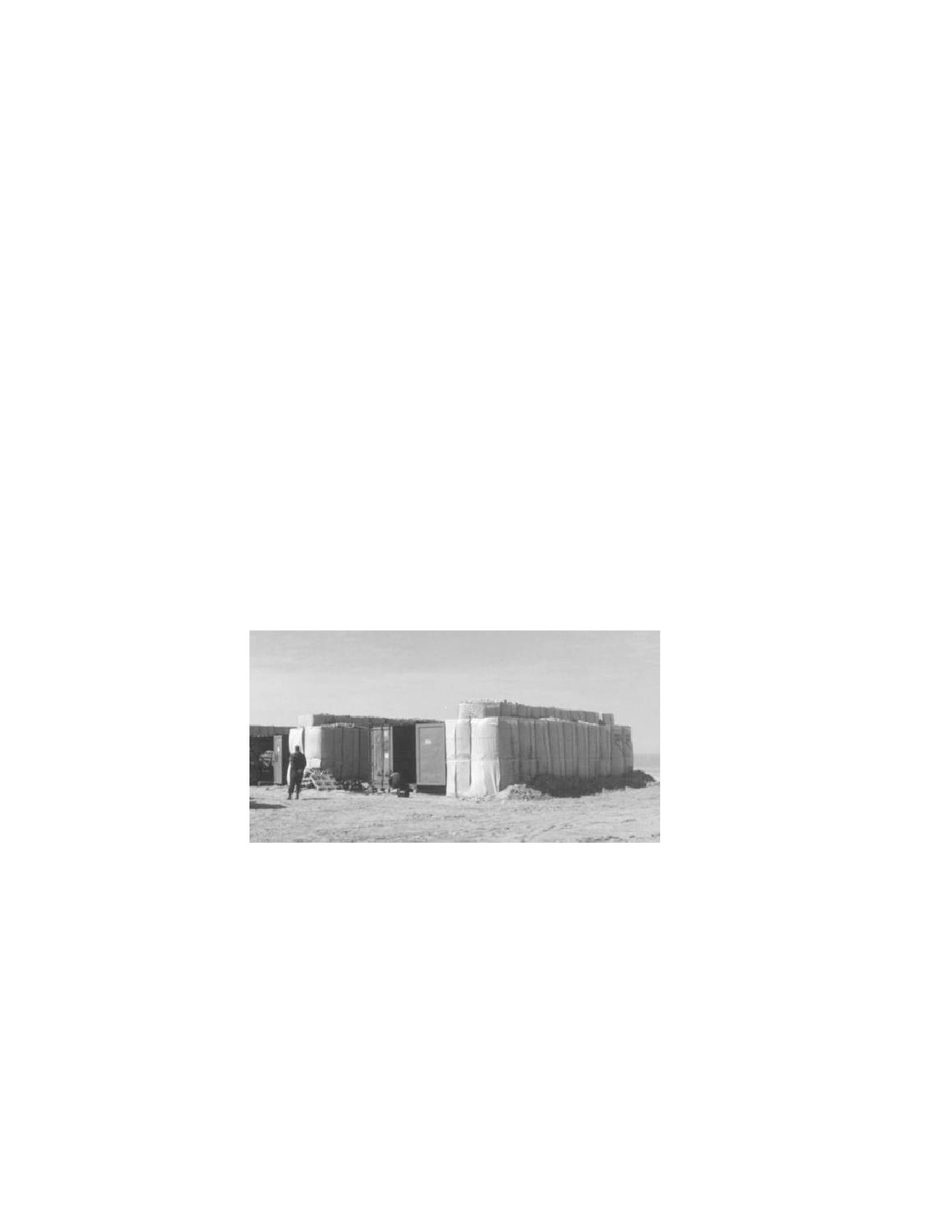
Instead of conventional earth embankments which have certain slopes and which are therefore space
consuming,
‘big bags’ or concertainers can be used
(e.g. Hesco Bastion Concertainers). These
concertainers must be filled with a material (like sand) that stops ammunition fragments and that does not
contribute to debris throw.
Figure 1.2.1.a Example of field barricades (ref. AC/258 DA(ST)IWP1-99).
In case of storage of HD1.2 and HD1.3 articles it is recommended that an effective roof constructions be
applied. The roof will protect the stored ammunition for external threats and minimise explosion effects (like
ammunition fragments, lobbed ammunition, heat radiation), especially during the first minutes after alarm
when evacuation of personnel will take place. Proposed effective roof constructions for out-of-area
circumstances are, for instance, earth covered plates of steel or concrete prefab slabs.
-IV-2-11-
Change 3