MANUAL OF NATO SAFETY PRINCIPLES FOR THE STORAGE OF MILITARY AMMUNITION AND EXPLOSIVES (May 2010) - page 16

NATO/PFP UNCLASSIFIED
AASTP-1
(Edition 1)
Section IV - Explosives Hazards Mitigation Methods.
3.2.4.1. Facility Layout
a)
A single-chamber facility with a straight access tunnel leading from the
chamber to the portal is a “shotgun” magazine because blast and debris
behave as if fired from a gun. More complex facility layouts will provide
reductions in exit pressures.
b)
The side on pressure, the side on pressure impulse, dynamic pressure and
the dynamic pressure impulse decrease as the volume increases.
c)
Distributing munitions over several storage chambers may control the size of
an initial explosion. Proper separation or hazard mitigating constructions can
limit subsequent damage.
3.2.4.2. Exits
a)
The exits from underground storage sites should not emerge where they
direct blast, flame, and debris hazards to Exposed Sites, ES, such as other
entrances, buildings, or traffic routes.
b)
Connected chambers and cave storage sites should have at least two exits.
Exits should be separated by at least the chamber interval.
3.2.4.3. Branch Passageways
a)
When a main passageway has one exit, branch passageways should be
inclined at an angle where they join the main passageway to direct the flow
field towards the exit. This inclination should provide for vehicle access.
Angles between 40 degrees and 70 degrees are normally appropriate.
b)
The rock thickness between the chamber and the main passageway should
be at least equal to or greater than the chamber interval. Otherwise, an
explosion in a chamber might destroy the main passageway and prevent
access to stocks of ammunition and explosives in the other chambers.
NATO/PFP UNCLASSIFIED
-III-2-13-
Change 3

NATO/PFP UNCLASSIFIED
AASTP-1
(Edition 1)
3.2.4.4. Blast Closures
a)
High-pressure closures are large blocks constructed of concrete or other
materials that can obstruct or greatly reduce the flow of blast effects and debris
from an explosion from or into a storage chamber. For chamber loading
densities of about 10 kg/m3 or above, closure blocks will contain 40 percent or
more of the explosion debris within the detonation chamber, provided the block
is designed to remain intact. If a closure block fails under the blast load, it will
produce a volume of debris in addition to that from the chamber itself.
However, since the block’s mass and inertia are sufficient to greatly reduce the
velocity of the primary debris, the effectiveness of other debris-mitigating
features, such as debris traps, expansion chambers and barricades is
increased. Debris traps and expansion chambers intended to entrap debris
must be designed to contain the full potential volume of debris, based on the
maximum capacity of the largest storage chamber.
b)
These debris mitigation features were investigated in the tests described in
Reference [7]. These tests showed that such measures can be very effective,
however, no quantitative figures for the reduction of the adit debris throw were
derived. Furthermore, it was shown that a proper design of the mitigation
measures is very important. Sample drawings of the features that proved to be
effective for the tested configurations are in Reference [5].
c)
An alternative, full-scale tested; design for a high-pressure closure device, the
Swiss-Klotz [4], is shown in Figure 2-III. This device is highly effective up to
chamber loading densities of 28 kg/m3. A special advantage of this Klotz is that
it is movable and can be closed during times when access to the storage
chamber is unnecessary.
d)
In case of an explosion inside the storage chamber and a Klotz in closed
position, practically all of the hazardous debris as well as the explosion gases
will be trapped inside the storage chamber, thereby reducing these hazardous
effects to virtually insignificant levels. In case the Klotz is in open position, it will
be pushed into the closed position by the explosion gases within approximately
100 ms, letting pass only a small fraction of the total amount of debris and
gases.
e)
In any case, using a properly designed high-pressure closure device in
conjunction with a portal barricade will lower the debris hazard to a level where
specific debris QD considerations will not be required. Other combinations of
mitigation features will also reduce adit debris throw to a great extent. The
remaining adit debris hazard has to be assessed based on the actual facility
layout and quantified by means of suitable tests.
f) Blast doors that are protected from primary fragments have proven effective for
loading densities up to 10 kg/m3.
NATO/PFP UNCLASSIFIED
-III-2-14-
Change 3
NATO/PFP UNCLASSIFIED
AASTP-1
(Edition 1)
Figure 2-III:
The Swiss-Klotz-Layout
Ground Plan
Storage
Chamber
Access
Tunnel
Klotz in "open"
Klotz in "closed"
-position
-position
Longitudinal Section
Storage
Hydraulic moving mechanism
Chamber
Access
2.50
Tunnel
Moveable reinforced concrete Klotz
0 m
10 m
Heavily reinforced concrete abutment
NATO/PFP UNCLASSIFIED
-III-2-15-
Change 3

NATO/PFP UNCLASSIFIED
AASTP-1
(Edition 1)
3.2.4.5. Expansion Chambers
a)
Expansion chambers are so-named because of the volume they provide for
the expansion of the detonation gasses behind the shock front as it enters the
chamber from a connecting tunnel. Some additional degradation of the peak
pressure at the shock front occurs as the front expands into the chamber and
reflects from the walls.
b)
Expansion chambers have other practical purposes. They serve as
loading/unloading chambers, as weather protected areas for the transfer of
munitions from trucks to storage chambers, and as turn-around areas for
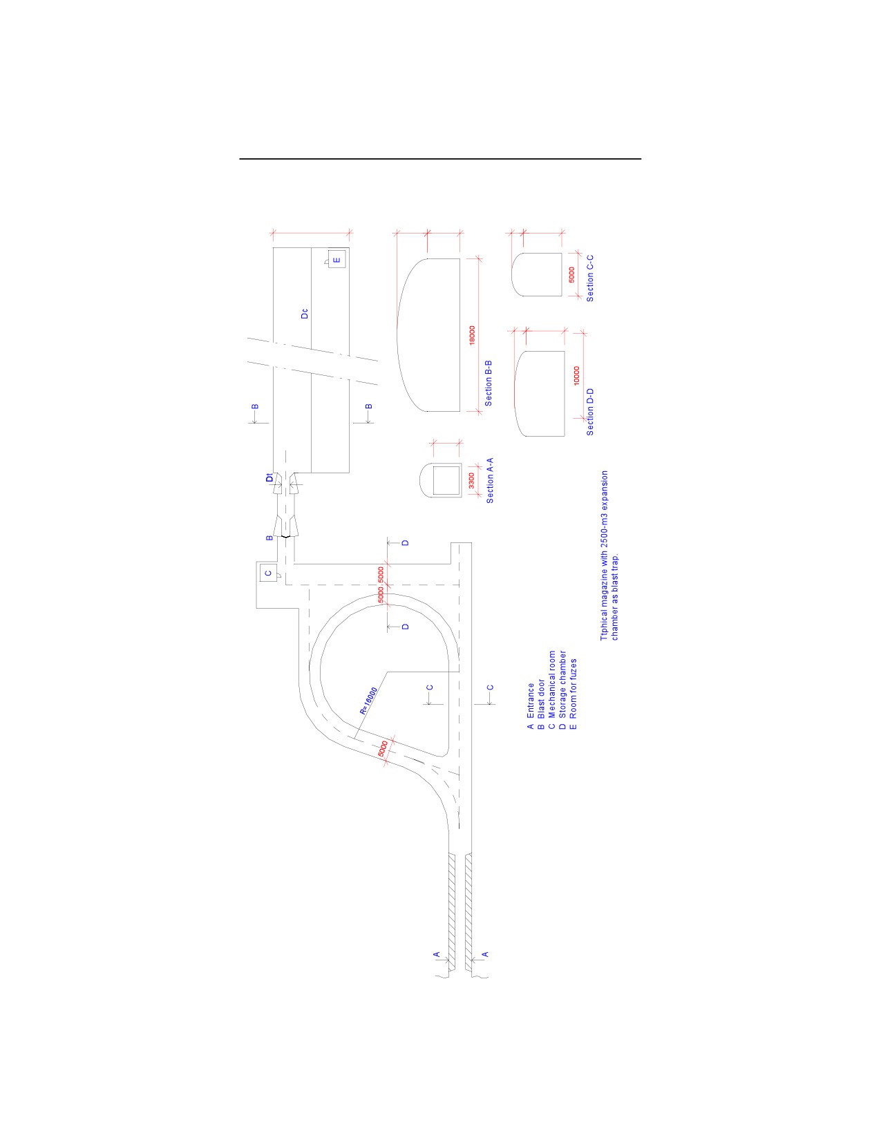
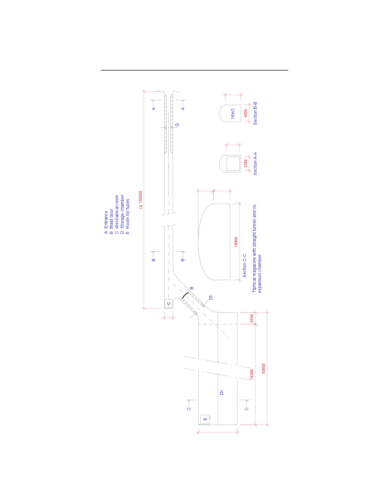
transport vehicles. Figures 2-IV and 2-V illustrate underground facilities with
and without expansion chambers.
3.2.4.6. Constrictions
a)
Constrictions, which may be used for mitigating explosives hazards, are short
lengths of tunnel with reduced cross sectional area.
b)
A constriction at a chamber entrance reduces the magnitude of airblast and
thermal effects entering chambers near one in which an explosion might
occur. A constricted chamber entrance also reduces the area, and hence the
size of a blast door installed to protect the chamber contents.
c)
A constriction intended to reduce airblast issuing from an exit of an
underground storage facility should be located within five tunnel diameters of
the exit.
d)
Although constrictions located more than five tunnel diameters from exits will
reduce pressures by delaying the release of energy [8, 9], their effects on
pressure versus distance must be considered on a site-specific basis.
3.2.4.7. Debris Traps within the Underground Facility
a)
Debris traps are excavations in the rock at or beyond the end of sections of
tunnel, designed to catch debris from a storage chamber detonation. Debris
traps should be at least 20 percent wider and 10 percent taller than the
branch passageway from the chamber whose debris it is intended to trap, with
a depth (measured along the shortest wall) of at least one tunnel diameter.
b)
An expansion chamber may be effective for trapping debris. Tunnels entering
or exiting the chambers must either be offset in axial alignment by at least two
tunnel widths or its axis must be offset at least 45 degrees from the centerline
of the tunnel associated with the chamber [5].
NATO/PFP UNCLASSIFIED
-III-2-16-
Change 3
NATO/PFP UNCLASSIFIED
AASTP-1
(Edition 1)
Figure 2-IV:
Magazine with Expansion Chamber
18000
3600
3850
1400
4550
1400
4550
3000
NATO/PFP UNCLASSIFIED
-III-2-17-
Change 3
NATO/PFP UNCLASSIFIED
AASTP-1
(Edition 1)
Figure 2-V:
Magazine without Expansion Chamber
4550
3000
3600
3850
4000
18000
NATO/PFP UNCLASSIFIED
-III-2-18-
Change 3

NATO/PFP UNCLASSIFIED
AASTP-1
(Edition 1)
3.2.4.8. Blast Traps
a)
Blast traps may be used to reduce the intensity of blast leaving or entering a
passageway. They may be used to attenuate the blast issuing from the adit of
an underground site, thus reducing hazard to people and property in the
vicinity. They may also be used to reduce the blast entering an adjacent
underground site, and to diminish the hazard to other ammunition. The effect
of various blast traps will be a function of the geometrical design of the blast
traps, and the peak side on pressure, the side on pressure impulse, the
dynamic pressure and the dynamic pressure impulse of the incident blast
wave. Fixed reduction figures can therefore not be given. The design of
effective blast traps is a specialized subject.
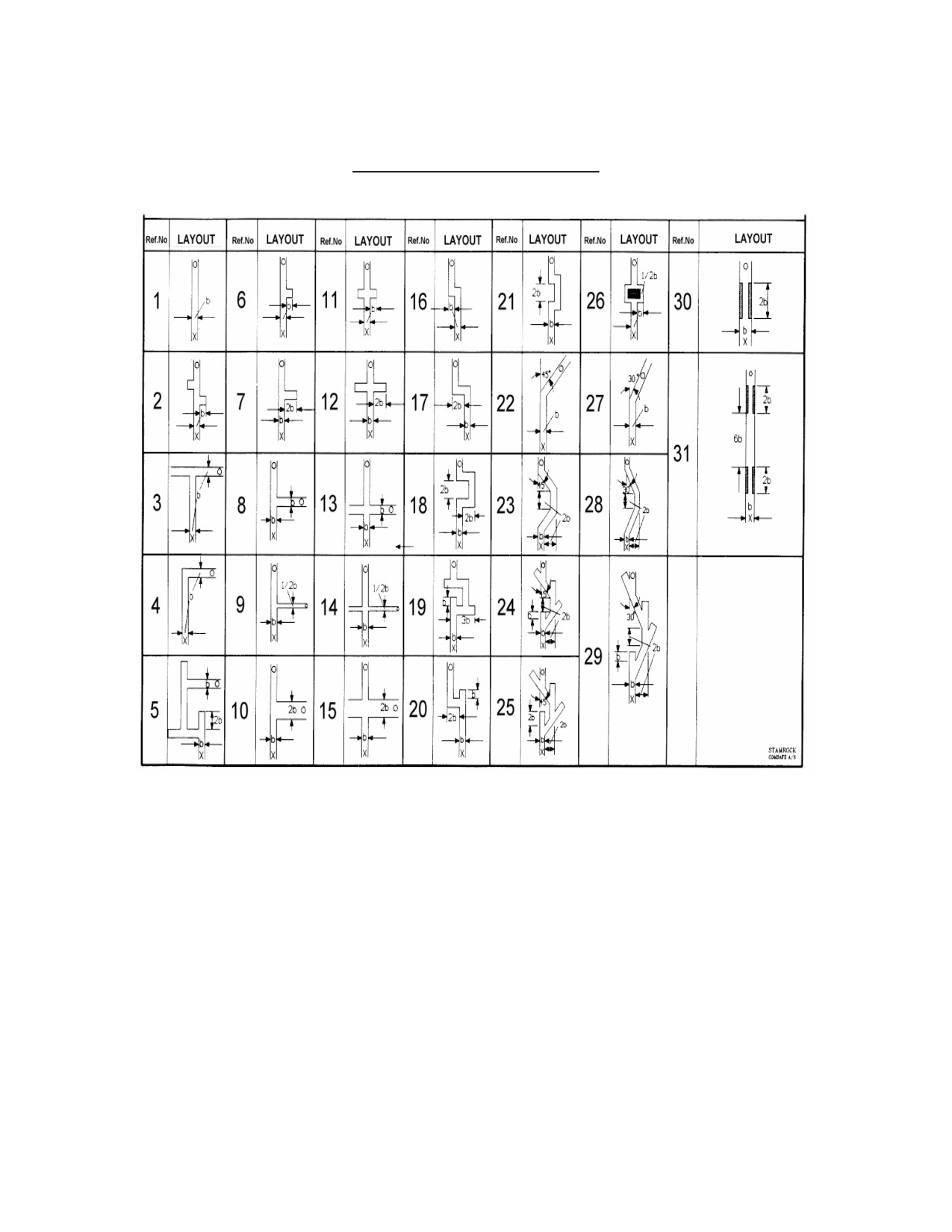
b) Various types of blast traps are shown in Figure 2-VI. The relative decrease of
pressure and impulse, and thereby the effect of these blast traps, is in most
cases dependent upon their locations. Some of the limitations are also
indicated in the figure. It is noteworthy that not all designs of blast traps are
reversible.
c) For maximum blast reduction, the length of blast traps built as dead end
tunnels should be at least half the length of the blast wave. This may result in
a considerable extension of these traps in the case of large quantities of
explosives.
3.2.4.9. Portal Barricade
a)
Airblast
Airblast exiting the portal of an underground facility involve directional, very
intense gas flow fields along the extended centerline of the tunnel exit.
Therefore, the shock wave on the extended centerline does not attenuate as
rapidly as that of a surface burst. However, a barricade in front of the portal
intercepts this intense flow field and directs it away from the extended
centerline axis. This redirection of the flow field allows shock waves traveling
beyond the portal barricade to attenuate as an above ground distributed
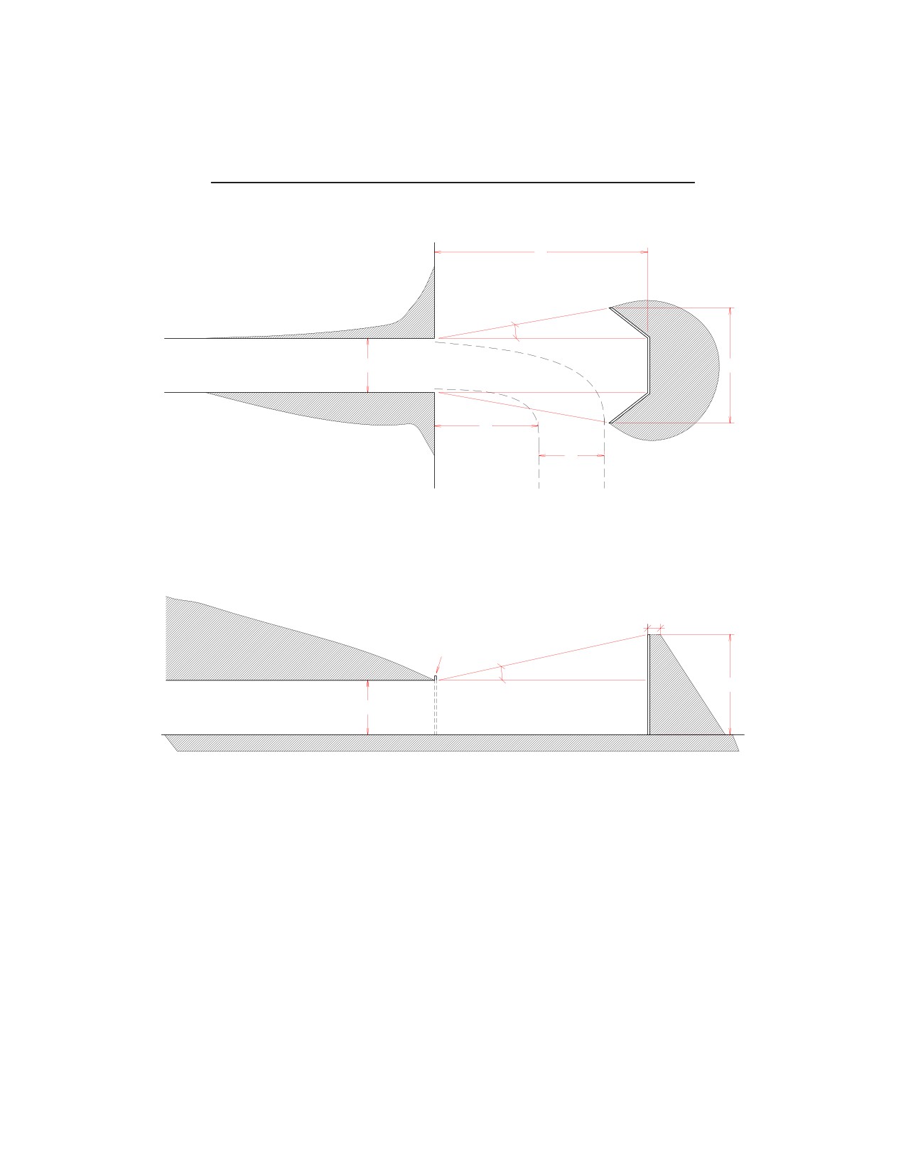
source so that isobar contours become more circular. Figure 2-VII provides an
example of a portal barricade.
NATO/PFP UNCLASSIFIED
-III-2-19-
Change 3
NATO/PFP UNCLASSIFIED
AASTP-1
(Edition 1)
Figure 2-VI:
Blast Traps
Turns, crossovers, obstacles and changes of cross section can be used to reduce
the peak overpressure and positive impulse of blast in passageways. The diagrams
in this figure illustrate some of the many possible designs. The Blast k assumed to
travel from the point indicated by a cross to that shown by a dot. Critical dimensions
are indicated as multiples of passage diameter “b”.
Some designs have comparatively little effect reducing the blast by only 10 %
compared with the straight-through passageway in Ref. No 1, whereas others reduce
the blast by as much as 80 %. It is therefore necessary to determine the actual effect
of a chosen design by measurements in a model using properly scaled and located
explosive charges.
NATO/PFP UNCLASSIFIED
-III-2-20-
Change 3
NATO/PFP UNCLASSIFIED
AASTP-1
(Edition 1)
Figure 2-VII:
Portal Barricade Location, Height and Length
S
φ
Tunnel
W
L
R
V
a. Plan View
S = Stand off distance from portal (1 to 3 tunnel widths)
R = Turning rasdius of munition transport vehicles
V = Width of transport vehicles
L = Length of barricade
W = Tunnel width at portal
φ = Single angle [10 degrees minimum]
C
Portal
θ
H
Tunnel
h
a. Elevation View
C = Crest Width [See DEF 421-80-04]
H = Height of barricade
h = Height of tunnel
θ = Elevation angle [10 degrees minimum]
NATO/PFP UNCLASSIFIED
-III-2-21-
Change 3

NATO/PFP UNCLASSIFIED
AASTP-1
(Edition 1)
CHAPTER 3 - QUANTITY-DISTANCES
Section I - General
3.3.1.1. Types and Effects
a)
Types
1.
This section details how to predict QD based on criteria given in para
3.1.1.2. for the underground storage of military ammunition and
explosives. Underground storage typically includes natural caverns and
excavated chambers. Recommendations in this section shall only be
used when the minimum distance from the perimeter of a storage area
to an external surface exceeds
600 mm and 0.1·Q1/3
(m, kg).
Otherwise, use aboveground siting criteria. This section addresses
explosives safety criteria both with and without rupture of the cover.
2.
Ground shock, debris, and air blast from an accidental explosion in an
underground storage facility depend on several variables, including the
local geology and site-specific parameters. These parameters vary
significantly from facility to facility. Consequently, distances other than
those listed below may be used provided approved experimental or
analytical data indicate that the desired protection can be achieved.
See below for default methods to determine QD.
The QD for tolerable ground shock is the same in all directions for
homogeneous, geological media, whereas QDs for other hazards
(blast, thermal, impulse, etc.) vary markedly in different directions.
Variations in QDs in different directions arise from configuration-
specific features such as the locations of adits and ventilation shafts,
hazards mitigating designs, and terrain. The acceptable QD in a given
direction is generally taken as the maximum QD determined for the
various hazards.
3.
QD siting requirements of this section may be determined from the
applicable equations or by interpolating between figure entries.
b)
Effects
The following effects, peculiar to underground storage sites, must be taken
into consideration for quantity-distance purposes:
NATO/PFP UNCLASSIFIED
-III-3-1-
Change 3

NATO/PFP UNCLASSIFIED
AASTP-1
(Edition 1)
1.
Inside the Underground Installation:
The volume available to an expanding shock front is less in an
underground configuration than it is in an aboveground configuration.
Because of this limited space, an explosion in an underground facility
typically results in long-duration, high pressures and temperatures that
spread throughout the entire volume available to the shock front.
Unless robust engineered designs (doors and/or other closing devices)
are used to separate various parts of the facility, these long-duration
blast effects spread throughout the entire underground complex. Doors
or other closing devices must be properly designed and, in the case of
doors, closed to provide the desired separation.
An initial event in Hazard Division 1.2 and 1.4 materials usually starts a
fire, which is sustained by burning packages and components of the
ammunition. This process causes additional explosions, likely at
increasing frequency, until combustible materials in the site have been
consumed. The results of these repeated explosions in the confined
space underground will depend on the type and quantity of the
substances in each unit of ammunition and the type of explosion
produced.
2.
Outside the Underground Installation:
Blast waves from adits exhibit highly directional flow-fields along the
extended centerline of the passageway. Consequently, the blast wave
effects (overpressure and impulse) do not attenuate as rapidly along
the centerline axis as they do off the centerline axis.
The following effects should be considered for an external ES:
a)
Blast from tunnel adits
b)
Blast from craters, if the rock cover is insufficient.
c)
Debris from tunnel adits
d)
Debris from cratering
e)
Ground Shock
f)
Flame and hot gases
NATO/PFP UNCLASSIFIED
-III-3-2-
Change 3

NATO/PFP UNCLASSIFIED
AASTP-1
(Edition 1)
3.3.1.2. Quantity-Distances
a)
Inside the UG Installation
QD should be determined for the following:
1.
Chamber Intervals
2.
Loading/Unloading Dock
3.
Explosives Workshop Distance (EWD)
4.
Inspection
b)
Outside the UG Installation
QD should be determined for the following:
1.
Inhabited Building Distance (IBD)
2.
Public Traffic Route Distance (PTRD)
3.
Explosives Workshop Distance (EWD)
4.
Earth-covered Magazine Distance (ECMD)
5.
Aboveground Magazine Distance (AGMD)
3.3.1.3. Net Explosives Quantity (NEQ)
For siting purposes, the NEQ is the total quantity of explosives material that
must be included in defining a potential event. Part I, paragraph 1.4.2.5.
provides guidance for finding the appropriate NEQ for sites containing
materials with different Hazard Classes.
3.3.1.4. Measuring Quantity-Distances
a)
Inside the Underground Installation.
The Chamber Interval is the shortest distance between the walls of two
adjacent chambers. The subdivision of a cavern requires construction of
massive barricades to close the gaps in the natural rock and to isolate one
site or chamber from any other. The thickness of these barricades should be
equal to the chamber intervals.
NATO/PFP UNCLASSIFIED
-III-3-3-
Change 3

NATO/PFP UNCLASSIFIED
AASTP-1
(Edition 1)
b)
Outside the Underground Installation.
Distances to ESs outside the underground facility are normally measured as
radial distances (see below) unless conditions make such a procedure clearly
unreasonable:
1.
Distances determined for airblast, debris, and thermal effects issuing
from tunnel openings shall be the minimum distance measured from
the openings to the nearest wall or point of the location to be protected.
Extended centerlines of the openings should be used as reference
lines for directional effects.
2.
A distance determined by ground shock should be measured from the
nearest wall of a chamber or a cavern containing ammunition or
explosives to the nearest wall or point of the location to be protected.
3.
A distance determined for air blast and debris from a breached cover
shall be the minimum distance from the centre of the breach (CCB), at
ground surface level, to the location to be protected (See Figures 3-
XXIV and 3-XXV).
NATO/PFP UNCLASSIFIED
-III-3-4-
Change 3

NATO/PFP UNCLASSIFIED
AASTP-1
(Edition 1)
Section II - Hazard Division Material Dependence
3.3.2.1. Hazard Division 1.1, 1.3, 1.5 and 1.6 materials
a)
Distances shall be determined from the total quantity of explosives,
propellants, pyrotechnics, and incendiary materials in the individual chambers,
unless the total quantity is subdivided to prevent rapid communication of an
incident between subdivisions. All Hazard Divisions 1.1, 1.3, 1.5, and 1.6
material subject to involvement in a single incident shall be assumed to
contribute to the explosion yield.
b)
A connected chamber or cavern storage site containing Hazard Division 1.1 or
1.3, 1.5 and 1.6 materials shall be treated as a single chamber site, unless
explosion communication is prevented by adequate subdivision or chamber
separation.
c)
HD 1.3 material should be treated as HD 1.1 material when it is stored
underground.
3.3.2.2. Hazard Division 1.2 materials
a)
The hazard to exterior ESs from primary fragments where a line-of-sight path
exists from the detonation point to the ES is the only explosives safety hazard
of concern for HD 1.2 materials.
b)
When line-of-sight conditions exist, use distances common to aboveground
situations.
c)
QD requirements do not apply if the exterior ES is located outside the line-of-
sight or if barricades (constructed or natural) intercept fragments issuing from
an opening.
3.3.2.3. Hazard Division 1.4 materials
Exterior: Exterior explosives safety hazards are not normally significant for
Hazard Division 1.4 materials. Accordingly, QD requirements do not apply for
Hazard Division 1.4 materials.
NATO/PFP UNCLASSIFIED
-III-3-5-
Change 3

NATO/PFP UNCLASSIFIED
AASTP-1
(Edition 1)
Section III - Chamber Interval
References [7-10] deal with chamber intervals.
3.3.3.1. Hazard Divisions 1.1, 1.3, 1.5, and 1.6
a)
Three modes by which an explosion or fire can be communicated are rock
spall, propagation through cracks or fissures, and airblast or thermal effects
traveling through connecting passages. Minimum storage chamber separation
distances are required to prevent or control the communication of explosions
or fires between donor and acceptor chambers.
The minimum chamber separation (Dcd) is 5 m for HD 1.1, 1.3, 1.5, and 1.6
materials.
b)
Prevention of major damage by rock spall.
The chamber separation distance is the shortest distance
(rock/concrete
thickness) between two chambers. When an explosion occurs in a donor
chamber, a shock wave propagates through the surrounding rock. The
intensity of the shock decreases with distance. For small, chamber separation
distances, the shock may be strong enough to spall the rock/concrete walls of
acceptor chambers.
For hard rock with no specific protective construction, the minimum, chamber
separation distance, Dcd, required to prevent major damage by spall depends
on the chamber loading density (γ) as:
1/3
3
D
cd
=
. ⋅Q
(γ≤
50 kg
/
m
)
Eq. 3.3.3-1
and
1/3
3
D
=
. ⋅Q
(γ>
50 kg
/
m
)
Eq. 3.3.3-2
cd
3
Example (γ≤
50 kg
/
m
):
Q = 200,000 kg
Dcd = 1.0 · 58.48 = 58.5 m
For soft rock (See para 3.3.4.3.a), at all loading densities, the separation
distance is:
1/3
D
=
. ⋅Q
Eq. 3.3.3-3
cd
Example:
NATO/PFP UNCLASSIFIED
-III-3-6-
Change 3

NATO/PFP UNCLASSIFIED
AASTP-1
(Edition 1)
Q = 200,000 kg
Dcd = 1.4 · 58.48 = 82 m
c)
Prevention of propagation by rock spall
If damage to stored munitions in the adjacent chambers is acceptable, the
chamber separation distance can be reduced to the distance required to
prevent propagation of the detonation by the impact of rock spall against the
munitions. For smaller distances, propagation is possible. Propagation by rock
spall is practically instantaneous because time separations between donor
and acceptor explosions may not be sufficient to prevent coalescence of blast
waves. Unless analyses or experiments indicate otherwise, explosives
quantities subject to this mode must be added to other donor explosives to
determine NEQ. For loading densities up to 270 kg/m³, when no protective
construction is used, the separation distance, Dcd, to prevent explosion
communication by spalled rock is:
1/3
D
cd
=
. ⋅Q
Eq. 3.3.3-4
Example:
Q = 200,000 kg
Dcd = 0.6 · 58.48 = 35 m
When the acceptor chamber has protective construction to prevent spall and
collapse
(into the acceptor chamber) the separation distance must be
determined on a site-specific basis but may be as low as:
1/3
D
=
. ⋅Q
Eq. 3.3.3-5
cd
Example:
Q = 200,000 kg
Dcd = 0.3 · 58.48 = 17.5 m
d)
Prevention of propagation through passageways
Blast, flame and hot gas may cause delayed propagation. Time separations
between the original donor event and the potential explosions of this mode will
likely be sufficient to prevent coalescence of blast waves. Consequently, for
purposes of Q-D siting, only the maximum credible explosives quantity need
be used to determine NEQ.
NATO/PFP UNCLASSIFIED
-III-3-7-
Change 3

NATO/PFP UNCLASSIFIED
AASTP-1
(Edition 1)
In order to protect assets, blast and fire resistant doors must be installed
within multi-chambered facilities. Evaluations of design loads on doors must
be made on a site-specific basis.
e)
Propagation by Flame and Hot Gas through Cracks and Fissures
Consideration must be given to the long-duration action of the explosion gas.
These quasi-static forces might form cracks in the rock that extend from the
donor to an adjacent (acceptor) chamber, thus making it possible for hot
gases to flow into this chamber and initiate an event. Significant factors for
this mode of propagation include the strength of rock, the existence of cracks
formed before the explosion incident, the type of barriers in cavern storage
sites, the cover and the loading density in the chamber. This mode of
propagation must be considered when final decisions about chamber
separation distances are made.
Thus, because of these cracks and fissures, propagation may occur beyond
1/3
D
cd
=
. ⋅Q
Eq. 3.3.3-6
Example:
Q = 200,000 kg
Dcd = 0.3 · 58.48 = 17.5 m
but not likely beyond;
1/3
D
=
. ⋅Q
Eq. 3.3.3-7
cd
Example:
Q = 200,000 kg
Dcd = 2 · 58.48 = 117 m
Site-specific analyses, using a sound geological survey, should be made to
determine proper intervals between chambers.
3.3.3.2. Hazard Division 1.2
Intervals between a chamber containing ammunition of Hazard Division 1.2
and adjacent chambers should be at least 5 m of competent rock unless structural
considerations apply. This applies also to barriers used to isolate chambers in a
cavern storage site.
NATO/PFP UNCLASSIFIED
-III-3-8-
Change 3

NATO/PFP UNCLASSIFIED
AASTP-1
(Edition 1)
3.3.3.3. Hazard Division 1.4
Intervals between chambers containing ammunition of Hazard Division 1.4
should be determined from structural considerations with no regard to the content of
ammunition. This applies also to barriers used to isolate chambers in a cavern
storage site
NATO/PFP UNCLASSIFIED
-III-3-9-
Change 3

NATO/PFP UNCLASSIFIED
AASTP-1
(Edition 1)
Section IV - Inhabited Building Distance (IBD)
IBD must be the largest of the distances for protection against airblast,
debris, and ground shock [1, 7].
3.3.4.1. Airblast [8-15]
a)
The side-on overpressure of 5 kPa defines IBD.
b)
An explosion in an underground storage chamber may produce external
airblast from two sources; the exit of blast from existing openings (tunnel
entrances, ventilation shafts, etc.) and the rupture or breach of the chamber
cover by the detonation. Required IBDs are independently determined for
each of these airblast sources, with the maximum IBD used for siting.
1.
A breaching chamber cover will produce external airblast. Use the
following table to site for IBD due to airblast produced by breaching of
the chamber cover. Values of IBD for airblast through the ruptured
cover are:
CoverThickness
IBD
Equation
1/3
Cover≤
0
1⋅Q
IBD forSurfaceBurst
Eq.334−1(a)
1/3
1/3
0
1⋅Q
<Cover≤0
2⋅Q
12IBD forSurfaceBurst
Eq.334−1(b)
1/3
1/3
0
2⋅Q
<Cover≤0
3⋅Q
14IBD forSurfaceBurst
Eq.334−1(c)
1/3
Cover>
0
3⋅Q
NegligibleAirblastHazard Eq.334−1(d)
2.
This paragraph defines airblast IBDs from openings in an underground
storage facility. The IBD for airblast must be considered for any opening.
The method for calculation of air blast in underground storage can be
divided in the following 3 steps:
1.
Calculation of air blast at the chamber exit
2.
Calculation of air blast at the tunnel adit
3.
Calculation of air blast outside the tunnel adit
NATO/PFP UNCLASSIFIED
-III-3-10-
Change 3

NATO/PFP UNCLASSIFIED
AASTP-1
(Edition 1)
a)
To a first approximation, the overpressure in the storage chamber
could be estimated with an algorithm of the form:
2/3
⎡
Q
⎤
p
= 1200
⋅
Eq. 3.3.4-1
c
⎢
⎥
⎣VC
⎦
where:
pc:
overpressure at the chamber exit, kPa
Q:
Mass of explosives material, kg
Vc:
Volume inside the chamber that is engulfed by
blast waves at the time the blast arrives at the
location of interest (m3).
b)
Air blast at the tunnel adit
The reduction of peak overpressure and change of duration from the
exit of a detonating chamber to the tunnel adit are calculated by using
different types of tunnel elements (see figure 3-I - 3-VI) to resemble
the actual configuration of the tunnel.
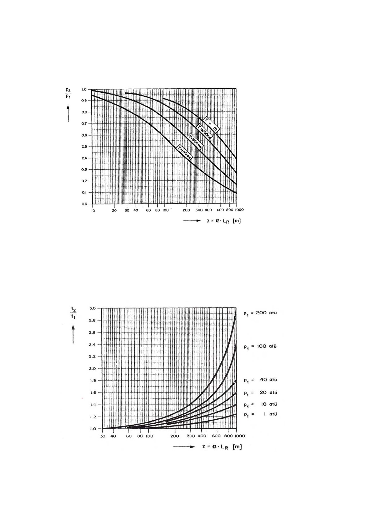
The following parameters and figure 3 and 4 are used to calculate the
reduction of peak overpressure in a tunnel element (friction element)
with a constant cross section and without junctions and turns.
LR = LS - 5 · d0
[8]
χ = α · LR
[9]
τ = α · t1
[10]
2
⎛
d
⎞
2/3
1/3
k
t
=
20⋅L
⋅ d
⋅⎜
⎟
[11]
1
k
0
⎜
⎟
d
⎝
0
⎠
Ls = Length of tunnel or tunnel element (m)
Lk =Length of chamber (m)
dk =Average equivalent diameter of the chamber(m)
LR =Effective length of tunnel (m)
d0 =Average equivalent diameter of the tunnel (m)
α =Friction coefficient for concrete (α = 1), shotcrete (α = 4) and
rock (α = 6)
χ =Coefficient for distance (m)
p1, p2 =Peak overpressure at the beginning respectively end of
the tunnel element (atm).
NATO/PFP UNCLASSIFIED
-III-3-11-
Change 3
NATO/PFP UNCLASSIFIED
AASTP-1
(Edition 1)
Figure 3-I: Diagram for calculation of reduction of pressure in a tunnel
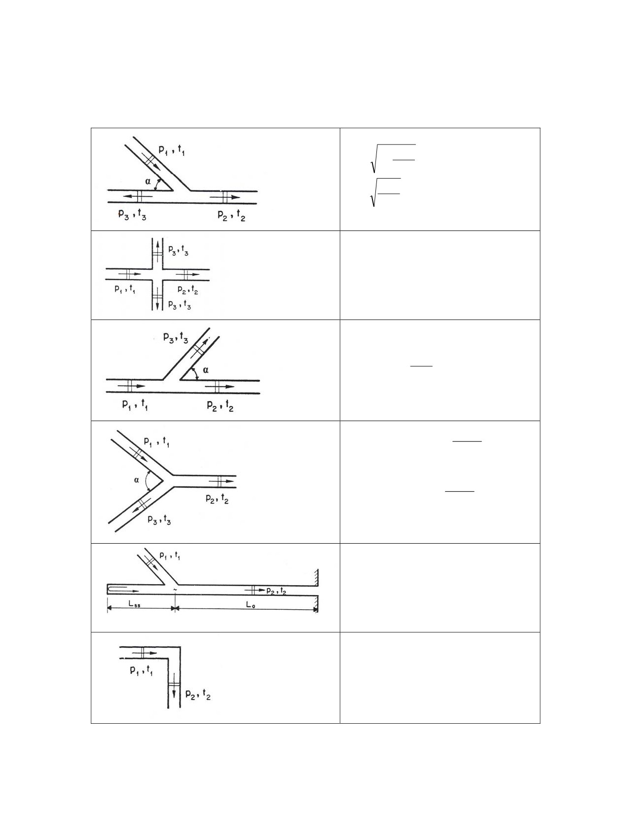
The change of duration will be calculated according to
p
1
- if the duration at the chamber exit is lower than 1000 ms, then
t
=
⋅t
2
1
p
2
- if the duration at the chamber exit is higher than 1000 ms, the change of duration
in the tunnel is calculated according to figure 4.
Figure 3-II: Diagram for calculation of change of duration in a tunnel
NATO/PFP UNCLASSIFIED
-III-3-12-
Change 3
NATO/PFP UNCLASSIFIED
AASTP-1
(Edition 1)
Figure 3-III: Description of tunnel elements
α
p
=
1−
⋅p
2
1
180°
α
p
=
⋅
p
3
1
180°
t
=t
=
⋅t
2
3
1
p
=
⋅p
2
1
p
= 0.25 ⋅ p
3
1
t
=t
=
⋅t
2
3
1
p
=
⋅p
2
1
⎛
α
⎞
p
=
0.8⋅⎜1−
⎟⋅p
3
1
⎝
180°⎠
t
=t
=
⋅t
2
3
1
2
⎛
⎞
⎛
α
⎞
⎜
⎟
p
2
=
0.9
−
0.6
⋅
⎜
⎟
⋅ p
1
⎜
180
°
⎟
⎝
⎠
⎝
⎠
⎛
α
⎞
p
=
⎜
0.2
+
0.6
⋅
⎟
⋅ p
3
1
⎝
180
°
⎠
t
=t
=
⋅t
2
3
1
If
L
≥2⋅L
0
ss
p
=
⋅p
2
1
t
=
t
2
1
If
L
<
2⋅L
0
ss
use tunnel elements(junctions)above
p
=
⋅p
2
1
t
=
t
2
1
NATO/PFP UNCLASSIFIED
-III-3-13-
Change 3
NATO/PFP UNCLASSIFIED
AASTP-1
(Edition 1)
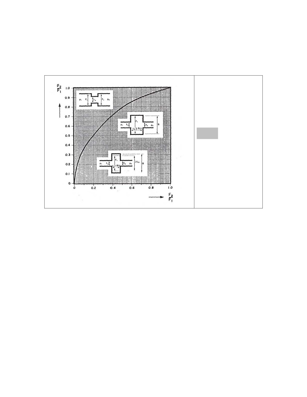
Figure 3-IV: Change of pressure and duration for constriction and expansion
chambers
t
=
t
2
1
F1 and F2 are tunnel
crossections
NATO/PFP UNCLASSIFIED
-III-3-14-
Change 3
NATO/PFP UNCLASSIFIED
AASTP-1
(Edition 1)
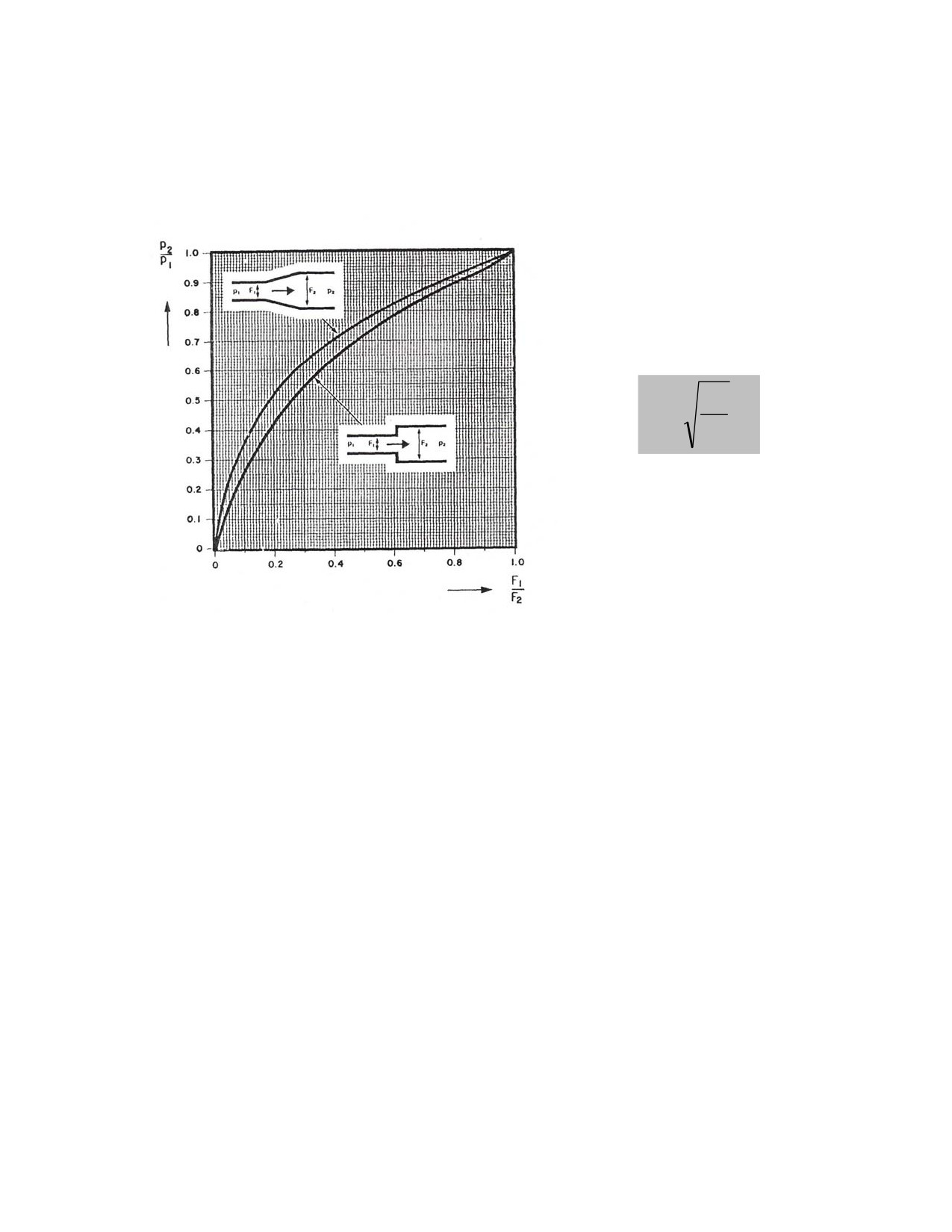
Figure 3-V: Change of pressure and duration for sudden and continuously
expansion tunnel element
F
1
t
=
⋅t
2
1
F
2
F1 and F2 are tunnel
crossections
NATO/PFP UNCLASSIFIED
-III-3-15-
Change 3
NATO/PFP UNCLASSIFIED
AASTP-1
(Edition 1)
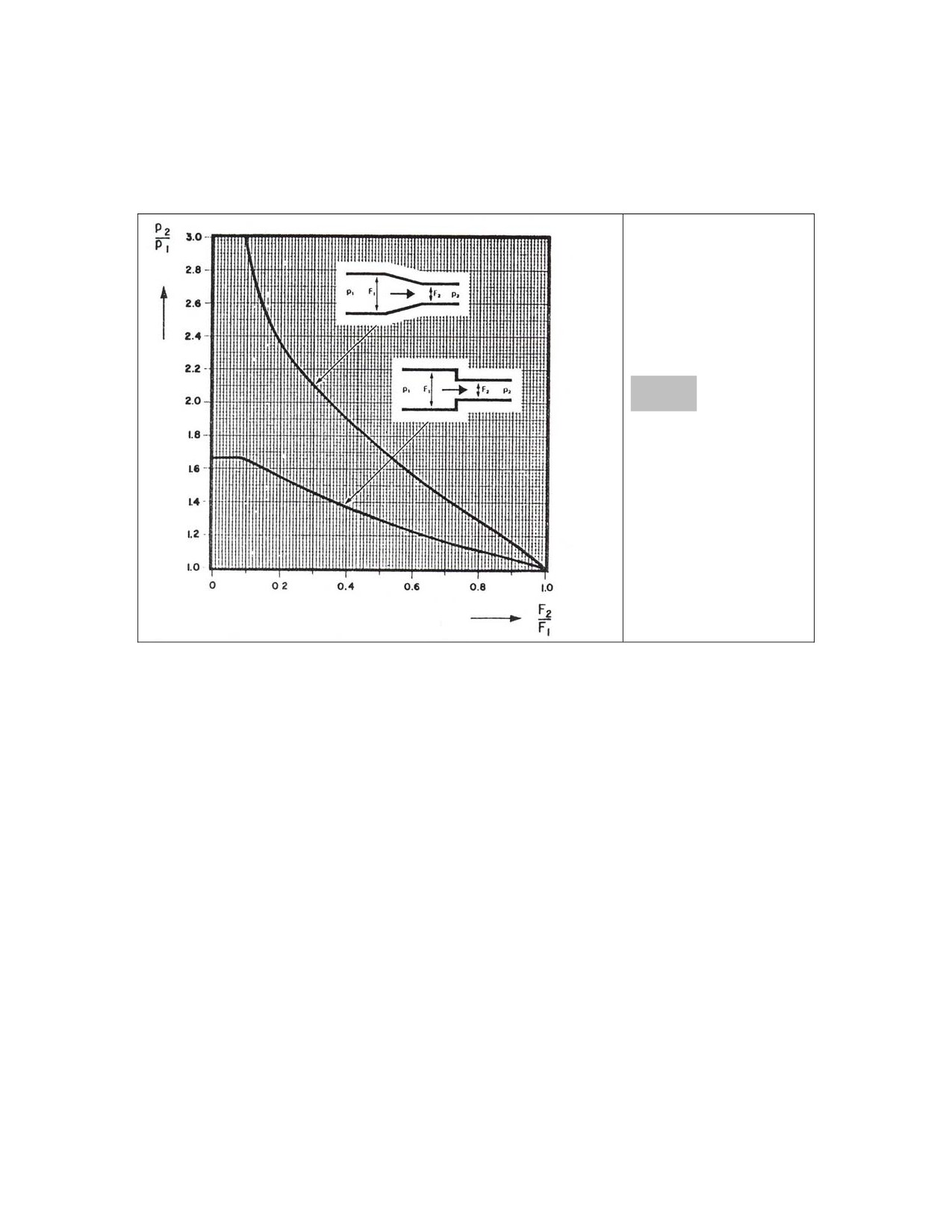
Figure 3-VI: Change of pressure and duration for sudden and continuously
constriction tunnel element
t
=
t
2
1
F1 and F2 are tunnel
crossections
Air blast outside tunnel adit
The resulting pressure in the tunnel adit could be expressed:
⎡
p
⎤
⎡
p
⎤⎡
p
⎤
2
3
n
p
=
p
⋅
⋅
Eq. 3.3.4-3
e
c
⎢
⎥
⎢
⎥⎢
⎥
⎣
p
1
⎦
⎣
p
2
⎦⎣
p
n−1
⎦
c)
The required distances for inhabitant building distance, public traffic
route distance and explosive workshop distance could then be
calculated. The distances calculated are valid for the axis of the tunnel.
0.74
⎡
p
⎤
e
IBD
=1.64⋅d
⋅
Eq. 3.3.4-4
te
⎢
⎥
⎣
⎦
0.72
⎡
p
⎤
e
IBD
=1.64⋅d
⋅
Eq. 3.3.4-5
te
⎢
⎥
⎣
⎦
NATO/PFP UNCLASSIFIED
-III-3-16-
Change 3
NATO/PFP UNCLASSIFIED
AASTP-1
(Edition 1)
0.66
⎡
p
⎤
e
IBD
=1.64⋅d
⋅
Eq. 3.3.4-6
te
⎢
⎥
⎣2
⎦
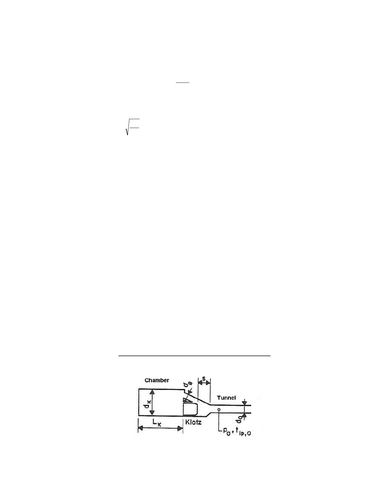
Where dte is the equivalent diameter in the tunnel exit (dte =
4A
)
π
d)
For a simple horizontal geometry (no barricade, a rapidly rising rock
face, an extended centerline normal to the rock face) the following
equation for off centerline axis can be used.
IBD(θ)=IBD(θ = 0)x [1+(θ/56)2] -0.74
Eq. 3.3.4-7
where:
θ:
horizontal angle off centerline in degrees
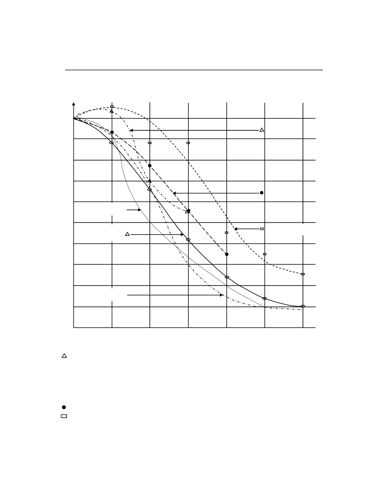
Large variations in directivity have been observed
(Figure
3-VII).
Therefore, it is recommended that carefully constructed models and
realistic exit pressures should be used to investigate directivity for an
actual site.
e)
High-Pressure Closure Block Designed to Remain Intact
References [4,
5] contain illustrative examples of a closure block
designs (Figure 3-VIII).
Figure 3-VIII:
Example of a Closing Block
NATO/PFP UNCLASSIFIED
-III-3-17-
Change 3
NATO/PFP UNCLASSIFIED
AASTP-1
(Edition 1)
Figure 3-VII:
Directivity Versus Azimuth with the Centre Line as Reference
F0
0
1.0
7 mbar
+
0.9
x
0.8
0.7
+
140 mbar
0.6
10-15 mbar
x
x
0.5
Model test
5 to 50mbar
50 mbar
0.4
0.3
+
0.2
x
50 mbar
+
+
x
0.1
+
0
0
300
600
900
120
1500
1800
LEGEND:
1.
“Free field overpressures resulting from shock waves emerging from open-ended shock tubes.”
Ballistic Research Lab. Mem. Report 1965.
x
2.
“An investigation of the pressure wave propagated from the open end of a 30 x 18 in. Shock tube.”
Atomic Weapons Research Establ. AWRE Report No. 0 - 60/65.
+
3.
“Underground Explosion Trials at Raufoss 1968. Measurement of air blast outside the tunnel.”
Intern Report X - 124. FFI 1969.
4. U.S Navy Gun Blast Committee: “Survey of Research of Blast”. First Interim Report, 1946.
5.
“Model tests to investigate external safety distances.” Fortifikatorisk notat 36/67, FBT
1967.
“One-dimensional blast wave propagation.” Fortifikatorisk Notat 49/69, FBT 196
NATO/PFP UNCLASSIFIED
-III-3-18-
Change 3

NATO/PFP UNCLASSIFIED
AASTP-1
(Edition 1)
For chamber loading densities greater than or equal to 10 kg/m3, IBD
may be reduced by 50% when a high-pressure closure block, designed
to remain intact in case of an explosion, is used.
For chamber loading densities lower 10 kg/m3 (but greater than 1.0
kg/m3), determine the reduction by the formula:
y(%) = 50 ⋅ log
(
γ
)
10
Eq. 3.3.4-5
where, y is the percentage reduction in IBD, and γ is loading density in
kg/m3. For loading densities lower than 1.0 kg/m3, use y(%) = 0.
f)
Portal Barricade
When a properly designed and located portal barricade [5, 7] is in front
of the opening, IBD for airblast along the extended tunnel axis may be
reduced up to 50 percent. Although the total airblast hazarded area
remains almost unchanged, its shape, for explosives safety
applications, becomes more circular.
NATO/PFP UNCLASSIFIED
-III-3-19-
Change 3

NATO/PFP UNCLASSIFIED
AASTP-1
(Edition 1)
3.3.4.2 Debris
Debris from an explosion in an underground facility may issue from
adits or other openings; failure of nearby structures
(portal,
barricades, etc.); and breaching of the geological cover over the
PES (crater debris).
Adit Debris
Introduction
a)
Debris throw from the adit is one of the most relevant hazardous
effects to be expected in case of an explosion in an underground
installation in rock. Adit debris consists of parts of ammunition and
its packaging, technical installations such as ventilation equipment,
doors and fire fighting installations, chamber and adit lining and
other reinforced concrete construction elements as well as of rock
rubble produced by the explosion effects. All these pieces of debris
are accelerated by the explosion gases escaping from the
installation and are thrown into the surroundings in front of the adit
portal.
b)
Adit debris throw mainly depends on the explosives weight Q
(NEQ, [kg]) stored in the installation and the geometry (ratio of
length to diameter - la/da-ratio) of the adit section just behind the
portal.
c)
Other factors, such as the loading density (explosives weight /
chamber or system volume), the centre of the explosion in the
chamber, the construction of the portal area and the geometry of
the whole adit may also influence adit debris throw. However, the
available data from tests and accidents was insufficient to derive
reliable relations.
Form of the IBD Contour Line and Influences
a) The general shape - resembling a cloverleaf - of the IBD contour
line for adit debris throw is shown in Figure I. The IBD contour line
is defined by points where the fragment density is one hazardous
fragment (energy greater than 79 Joules) per 56 m2 (≅ 0.0179
#/m2).
b) No closed formula exists for the shape of the IBD contour line.
Therefore, the line has to be constructed gradually, point per point.
NATO/PFP UNCLASSIFIED
-III-3-20-
Change 3

NATO/PFP UNCLASSIFIED
AASTP-1
(Edition 1)
c) The shape and size of the contour line is influenced by the
following three parameters:
- Net explosives quantity of the stored ammunition
NEQ [kg]
- Relevant length of the adit section behind the portal
la
[m]
- Average equivalent diameter of the adit (la)
da
[m]
d) The ratio la/da defines the portal parameter fp and the standard
deviation σ.
The portal parameter fp takes into account that a long small adit
leads to a more focused debris throw than a short adit with a large
cross section area. Large la/da values, therefore, lead to far
reaching but narrow IBD contour lines. The fp parameter influences
the maximum range of the IBD contour line.
The standard deviation σ defines the width of the IBD contour line.
Procedure to Calculate an IBD Contour Line
a)
Calculate the maximum range Ro max of the IBD contour line (Figure
3-IX).
− 4.025
−
A
Ro max = fp x
B
The parameter fp is a function of the la/da ratio. It is to be calculated
according to Figure 3-X. Typical examples on how to define the
la/da ratio are given in Figure 3-XI.
The A and B values are both a function of the NEQ.
A = -5.25 + 1.0 x ln(NEQ)
0.25
B = -0.0085 -
NEQ
A, B and fp values for typical amounts of NEQ and la/da ratios are
also given in the tables in Figure 3-XII.
b)
For a suitable number of Ro values (8 to 12, freely chosen, but Ro <
Ro max) calculate the reference value Do (Figure 3-IX).
Do =
exp(A + B x Ro/fp) where: exp(x) = ex and e = 2.718
NATO/PFP UNCLASSIFIED
-III-3-21-
Change 3