MANUAL OF NATO SAFETY PRINCIPLES FOR THE STORAGE OF MILITARY AMMUNITION AND EXPLOSIVES (May 2010) - page 15

AASTP-1
(Edition 1)
2.
Static electricity grounding (earthing) requirements.
3.
Maximum and/or minimum humidities.
4.
Clothing and foot-wear requirements.
5.
The maximum number of personnel to be in the workshop or laboratory at any one time.
6.
The maximum quantity of explosive items permitted in the building and/or to be worked on at any
one time.
7.
Any additional safety precautions necessary for the ammunition being worked on.
c)
Operations may proceed while the SOP are being printed provided a draft has been approved by the
Commanding Officer/Superintendent and is posted in the working area.
2.6.5.4.
Personnel and Explosive Limits
To reduce the risk of injury of personnel and damage to property the number of personnel employed, and the quantity of
ammunition within an explosives workshop should be kept to the minimum required to maintain the operation. Dividing
the overall quantity into separate bays or rooms, with substantial internal walls or barricades, will reduce the risk of
explosive propagation and probably reduce the effects of an explosives accident. The personnel and explosive limits vary
with each operation and should be included in the SOP.
b)
A personnel limit is to be assessed for each building, room or area in accordance with the following principles:
1.
The number of persons employed should be the minimum compatible with the highest standards of
safety, quantity and an even flow of work.
2.
The personnel limit should include all persons employed including those employed on the movement
of the ammunition or other tasks in the immediate vicinity.
3.
The limit may include up to two supervisors or inspectors even though their presence is not
continuous.
4.
The limit should be related to the size of the building and number of exits. Irrespective of other
considerations, each person is to have ample working space and suitable evacuation routes.
c)
A working explosive limit for each building, room or area should be assessed in accordance with the following
principles:
1.
It should not exceed the quantity permitted by available quantity-distances.
-II-6-14-
Change 3

AASTP-1
(Edition 1)
2.
The limit should represent the minimum number of containers or rounds required to maintain an even
and continuous flow of work.
3.
The working limit should include all ammunition held within the building and the immediate
vicinity. It should also include ammunition that has been processed or waiting to be processed,
whether on vehicles or on the ground.
4.
The possibility of reducing the hazard presented both inside and outside the building by the use of
adequate internal traverses should be considered.
d)
Signs should be conspicuously posted to provide the following information:
1.
The nature and type of ammunition being processed.
2.
Details of the operation i.e. re-boostering.
3.
The compatibility group, hazard division and fire class of ammunition.
4.
Personnel and explosive limits.
This information should be repeated as necessary for rooms or confined areas where special working conditions
are prescribed. The explosive limits may be stated in terms of NEQ and/or number of rounds or containers.
2.6.5.5.
Clean Working Areas
a)
Clean conditions may be described as a set of precautions that are taken in explosives laboratories, workshops,
proof areas, and certain magazines, to prevent the introduction of, or the contact of explosives with, extraneous
matter such as ferrous metals, aluminium or aluminium alloys or grit which might cause an explosion through
friction or spark.
b)
Working areas that are required to be maintained under clean conditions should be provided with a changing
lobby. The lobby should be divided by a barrier to indicate the clean area.
-II-6-15-
Change 3

AASTP-1
(Edition 1)
2.6.5.6.
Clothing for Clean Conditions
Clothing used for wear in explosives workshops or laboratories maintained under clean conditions should be
specified by the appropriate National Authority, and will normally include items such as spark-proof conductive
footwear, fire retardant coveralls and suitable hair covering.
2.6.5.7.
Static Electricity Precautions
a)
Ammunition workshops should be provided with conductive or anti-static flooring. Conductive flooring is
designed to provide a path of conductivity for the free movement of electrostatic charges, thereby preventing a
charge accumulation.
b)
Anti-static flooring differs from conductive flooring in that it offers greater resistance to the passage of electrical
current.
c)
Grounding (earthing) points should be available for equipment, tools and ammunition in explosives workshops,
to prevent a difference of electrical potential between operators and the material that they must handle.
d)
Conductive flooring and grounding (earthing) systems should be tested for continuity in accordance with
national specifications.
e)
Personnel working in explosives workshops should wear conductive footwear or copper chain, when conductive
flooring is present. Such safety devices should be tested frequently.
2.6.5.8.
Painting Operations
a)
Painting and stencilling operations should only be conducted in well ventilated rooms or outdoors.
b)
Spray painting operations, when conducted indoors, should be done in spray painting booths, except for minor
touch-up or stencilling using low pressure spray markers or aerosol containers.
c)
Operators and helpers should wear protective masks while spray painting is in progress, unless the spray booths
are properly exhausted so as to preclude exposure of personnel to toxic atmosphere.
-II-6-16-
Change 3

AASTP-1
(Edition 1)
2.6.5.9.
Heat Sealing Equipment
a)
The use of heat sealing equipment for packaging of ammunition in polyethylene is permitted under the
following conditions:
1.
The ammunition is suited to heat sealing.
2.
The heat sealing apparatus is approved.
3.
It is used in accordance with the manufacturer's instructions.
4.
It is properly maintained and inspected for serviceability and cleanliness before initial use and at the
beginning of each shift, and should be checked for cleanliness (absence of any spillings) before each
operation.
b)
The sealing equipment should be restricted for use as permitted by the host country within a transit magazine or
explosives workshop in a room or segregated area apart from other activities. However, heat sealing equipment
must not be permitted in a room maintained under clean conditions.
c)
Items to be heat sealed should be in serviceable condition and free of defects.
d)
Detonators and heat sensitive items such as propellants or explosive samples should be suitably packaged before
heat sealing.
2.6.5.10.
Tools
a)
Only non-sparking tools should be used in direct contact with exposed explosives or in rooms maintained under
clean conditions.
b)
Special or locally designed tools and equipment should not be used in ammunition operations nor should
modifications or alterations to approved tools or equipment be made without prior approval.
c)
Tools and appliances designed and provide for particular explosives operations should not be used for other
purposes without approval.
-II-6-17-
Change 3

AASTP-1
(Edition 1)
d)
Only those tools authorized for use by the applicable SOP for the operation being performed should be
permitted in the room or area.
2.6.5.11.
Closedown of Explosives Workshops
a)
When an explosives workshop is vacated all electrical installations and powered equipment other than essential
services should be switched off or disconnected. At the end of each working day the building should be secured.
b)
Ammunition remaining in the building should be subject to the following:
1.
During temporary breaks within the course of a working day, the ammunition may be left in position
provided it is safely stowed, and the explosive is not exposed.
2.
At the end of each working day ammunition may be left in the work area providing it is packaged,
(except for ammunition which is not normally stored in packages) and placed on the floor. Items
should be grounded (earthed) as applicable.
2.6.5.12.
Supervision
Constant supervision should be maintained by supervisory staff and all personnel should be safety conscious.
Each operator should be fully acquainted with any hazards associated with the ammunition on which he is
required to work. Before commencing an operation each operator should be familiarized with the particular task
that he will perform.
2.6.5.13.
Accident Involving Ammunition
a)
In the event of an accident or incident involving ammunition, all operations shall cease immediately and the
situation shall be reported to the Commanding Officer/Superintendent. Nothing shall be disturbed, except in the
interest of safety or as may be necessary to give assistance to injured persons. Precautions should be taken to
prevent unauthorized personnel from entering the area.
b)
Accidents involving ammunition shall be reported in accordance with national regulations.
-II-6-18-
Change 3

AASTP-1
(Edition 1)
Section VI - Destruction of Ammunition and Explosives
2.6.6.1
Introduction
a)
This section contains advice pertaining to the destruction (by open burning/open detonation) of ammunition
and explosives which has deteriorated or which has been declared surplus or obsolete. These recommendations
establish measures and procedures for minimizing the risk in destroying unwanted ammunition and explosives.
All destruction operations must be carried out in accordance with rules and regulations established by the
competent National Authority.
b)
This section does not deal with matters pertaining to Explosive Ordnance Disposal (EOD) emergency actions.
2.6.6.2
Selection Of Destruction Areas For Open Burning/ Open Detonation
The ideal destruction area is one with deep soil, free from loose rocks, where trenches and pits can be dug
easily and in which the risk of fire is negligible. In the selection of a permanent destruction area, the land
should be above rather than below the surrounding area, naturally drained. The destruction area must be as far
as possible from:
a)
magazines and other buildings in the explosives area;
b)
administration buildings and depot offices;
c)
public or inhabited buildings;
d)
overhead and underground cables;
e)
land drainage systems, water mains, sewers and underground pipelines;
f)
railway and highway cuttings, tunnels and embankments where earth shocks might undermine or cause debris
to fall on the tracks or roads;
g)
airfields and
h)
environmentally sensitive areas; such as areas containing wetlands, endangered species, or threatened plants.
-II-6-19-
Change 3

AASTP-1
(Edition 1)
2.6.6.3
Explosive Limits For Destruction Areas
a)
Explosives limits for destruction areas will vary because of local conditions. In establishing limits for items of
Hazard Division 1.1, 1.2, 1.3 and 1.4 involved in individual destruction operations, the maximum quantity to
be destroyed at any time must be determined carefully by the competent National Authority.
b)
When determining these limits, consideration must be given to:
1.
the maximum radius of fragment and debris hazards;
2.
the maximum radius of blast effects;
3.
shock transmission through the particular ground strata (e.g. high water tables or rock formations);
4.
the effects of overcast weather conditions; and
5.
the effects of wind.
2.6.6.4
Destruction Area Maintenance
a)
Fire breaks must be maintained around and within destruction areas as required.
b)
All trees, dry grass and underground within a radius of 60 m from the destruction point must be removed.
c)
The area should be restricted and marked as required by the competent National Authority.
2.6.6.5
Splinter-proof Shelters
Where Ammunition is being destroyed by detonation, a splinter-proof shelter should be provided as a control
point and to provide protection for personnel. Where provided, it must be located not less than 90 m from the
actual destruction point. Where a splinter-proof shelter is not provided, the Control Point should be located at
a sufficient distance from the destruction point in order to provide adequate safety to personnel.
2.6.6.6
Record Keeping
A record keeping system should be maintained that includes location of destruction, summary of items
destroyed, date of operation and other data required by the competent National Authority.
-II-6-20-
Change 3

AASTP-1
(Edition 1)
-II-6-21-
Change 3

AASTP-1
(Edition 1)
CHAPTER 7 - DETAILED INFORMATION RELATING TO HAZARDS FROM ELECTRO MAGNETIC
RADIATION TO AMMUNITION CONTAINING ELECTRO-EXPLOSIVE DEVICES
Chapter 7 is pending further review
Refer to AASTP-1 Part I Chapter 6
-II-7-1-
Change 3

AASTP-1
(Edition 1)
Annex II-B
ANNEX II-A
RESERVED
-II-A-1-
Change 3

AASTP-1
(Edition 1)
Annex II-B
ANNEX II-B
DETAILED INFORMATION RELATED TO
EARTH-COVERED MAGAZINES (IGLOOS)
SECTION I - TYPES OF IGLOOS
SECTION II - BLAST DATA FOR DESIGN OF IGLOOS
Detailed information can be found
PFP(AC/326-SG/5)D(2010)0001 Nationally Approved Structures, Ed 2, 2 December 2010
-II-B-1-
Change 3

NATO/PFP UNCLASSIFIED
AASTP-1
(Edition 1)
ALLIED AMMUNITION STORAGE AND TRANSPORT
PUBLICATION 1
(AASTP-1)
MANUAL OF NATO SAFETY PRINCIPLES
FOR THE STORAGE OF MILITARY
AMMUNITION AND EXPLOSIVES
PART III
UNDERGROUND EXPLOSIVES STORAGE
April 2010
NATO/PFP UNCLASSIFIED
-III-1-
Change 3

NATO/PFP UNCLASSIFIED
AASTP-1
(Edition 1)
TABLE OF CONTENTS
PART III
CHAPTER 1 - GENERAL
1
Section I - Introduction
1
3.1.1.1. Purpose
1
3.1.1.2. Design Environment Criteria
1
3.1.1.3. Limitations
2
3.1.1.4. Requirements
2
Section II - Definitions
3
3.1.2.1. General
3
3.1.2.2. Definitions
3
CHAPTER 2 - BACKGROUND INFORMATION
1
Section I - General
1
3.2.1.1. Optimized Underground Ammunition Storage Site (General Description)
1
3.2.1.2. Explosion Effects in Underground Ammunition Storage Sites
4
3.2.1.3. Advantages of Underground Storage
5
3.2.1.4. Disadvantages of Underground Storage
6
3.2.1.6. Storage Limitations
6
Section II - Design
8
3.2.2.1. General
8
3.2.2.2. Safety Requirements
8
3.2.2.3. Military Requirements
9
3.2.2.4. Financial Aspects
9
Section III - Equipment
10
3.2.3.1. Humidity Control and Ventilation
10
3.2.3.2. Electric Installations and Equipment
10
3.2.3.3. Lightning Protection
10
3.2.3.4. Transport and Handling Equipment
10
3.2.3.5. Fire-fighting Equipment
11
Section IV - Explosives Hazards Mitigation Methods
13
3.2.4.1. Facility Layout
13
3.2.4.2. Exits
13
3.2.4.3. Branch Passageways
13
3.2.4.5. Expansion Chambers
16
3.2.4.6. Constrictions
16
3.2.4.7. Debris Traps within the Underground Facility
16
3.2.4.8. Blast Traps
19
3.2.4.9. Portal Barricade
19
CHAPTER 3 - QUANTITY-DISTANCES
1
Section I - General
1
NATO/PFP UNCLASSIFIED
-III-TOC-1-
Change 3

NATO/PFP UNCLASSIFIED
AASTP-1
(Edition 1)
3.3.1.1. Types and Effects
1
3.3.1.2. Quantity-Distances
3
3.3.1.3. Net Explosives Quantity (NEQ)
3
3.3.1.4. Measuring Quantity-Distances
3
Section II - Hazard Division Material Dependence
5
3.3.2.1. Hazard Division 1.1, 1.3, 1.5 and 1.6 materials
5
3.3.2.2. Hazard Division 1.2 materials
5
3.3.2.3. Hazard Division 1.4 materials
5
Section III - Chamber Interval
6
3.3.3.1. Hazard Divisions 1.1, 1.3, 1.5, and 1.6
6
3.3.3.2. Hazard Division 1.2
8
3.3.3.3. Hazard Division 1.4
9
Section IV - Inhabited Building Distance (IBD)
10
3.3.4.1. Airblast [8-15]
10
3.3.4.2 Debris
20
3.3.4.3 Ground Shock
48
3.2
Classification of Building Damage
50
3.3
Prediction of Building Damage Index
50
Other Hazard Divisions
53
Section V - Public Traffic Route Distances (PTRD)
58
Section VI - Explosives Workshop Distance (EWD)
59
3.3.6.1. Potential Crater
59
3.3.6.2. Aboveground EW Located within the Maximum Dispersal Angle
59
3.3.6.3. Aboveground EW Located Outside the Maximum Angle of Dispersal
59
Section VII - Aboveground Earth-Covered Magazine (ECM)
60
Section VIII - Aboveground Magazine Distance (AGMD)
61
REFERENCES
1
NATO/PFP UNCLASSIFIED
-III-TOC-2-
Change 3

NATO/PFP UNCLASSIFIED
AASTP-1
(Edition 1)
CHAPTER 1 - GENERAL
Section I - Introduction
3.1.1.1. Purpose
This part of the Manual [1]† deals with special types of storage of ammunition
and explosives such as underground storage and storage aboveground in
circumstances other than normal for an aboveground depot. Although each chapter
contains both principles and technical details, it is necessary to refer to Part I and
Part II of the Manual for an explanation of the fundamental concepts and the
definitions of certain terms.
3.1.1.2. Design Environment Criteria
This part uses distances, specified by the criteria below, to achieve desired
levels of protection to personnel and property. Distances provided by the criteria do
not guarantee absolute safety. However, assuming an event, these distances do limit
the expectation of a severe injury or fatality to normally less than 1% for personnel in
the open or in a conventional building at Inhabited Building Distance (IBD).
Advisable criteria at IBD are:
Air blast overpressure:
5 kPa
Fragments and debris:
1 hazardous fragment per 56 m2
Actual particle velocity to be used at IBD for groundshock should depend on the
robustness of the structure under consideration and is discussed in page III.2.3
The criteria listed above are used in Part III, Chapter 3 to obtain required distances.
Special considerations that are not discussed in detail here are required to provide
levels of protection for historical monuments and sites, high-rise buildings, and
locations where many people are assembled.
When they are available, site-specific and configuration-specific tests and/or
analyses may be used to determine recommended distances.
† References are in Annex III A
NATO/PFP UNCLASSIFIED
-III-1-1-
Change 3

NATO/PFP UNCLASSIFIED
AASTP-1
(Edition 1)
When deciding distances that provide protection for personnel , the requirements of
Part II, para 2.5.5.5.d, para 2.5.5.6, Fig 5-XV, and Annex II A-D10 distance should
be considered. These are:
Airblast overpressure:
20-kPa side-on overpressure will not cause severe
injury to persons in the open.
Ground shock:
A velocity change of less than 3 m/s will not cause
severe injury to personnel.
Public Traffic Route Distance (PTRD) is normally 2/3 of IBD because moving traffic
is not continuously exposed. However, IBD should be used instead of PTRD where
there is a heavy traffic.
3.1.1.3. Limitations
Configurations of underground facilities will vary from site-to-site. Only a
limited number of possible configurations have been investigated. Site-specific tests
and analyses will be necessary if high-levels of confidence are required for the more
complex configurations.
Recommendations for underground storage are based on the best-available,
worldwide database of information. Recommendations are based on accidents or
scaled tests with non-responding steel models (1/100th to 1/20th scale) or rock
tunnels (1/8th to 1/3rd scale).
3.1.1.4. Requirements
Engineered structures and devices related to explosives safety must be designed to
90% confidence levels for collapse or failure with a given load (Part II, Para 2.3.2.2).
QD distances provided in this document are based on TNT-equivalencies for the
energetic materials that are involved. Significant differences in the TNT-equivalency
must be considered [3].
See Part I, Annex IA, Section 1, Para 2 [1] for rounding of Quantity-Distances.
NATO/PFP UNCLASSIFIED
-III-1-2-
Change 3

NATO/PFP UNCLASSIFIED
AASTP-1
(Edition 1)
Section II - Definitions
3.1.2.1. General
The following definitions are used in connection with underground storage.
For additional definitions, see Part I, Chapter 2, Section 2 [1].
3.1.2.2. Definitions
a)
Adit
A passage or tunnel leading into an underground storage site
b)
Chamber Interval
The interval between the natural or artificial walls of adjacent underground
storage chambers/sites
c)
Cover
The solid ground situated between the ceiling or the wall of an underground
chamber and the nearest exterior surface
d)
Crack
A short, primary discontinuity, which is not pervasive and may not be visible
e)
Crater
A hole or chasm in the cover (burden) caused by an underground explosion.
f)
Faulting
Motions in the earth’s crust resulting in failure of the rock mass and
concentrated displacements along failure planes, for instance discontinuities (joints,
fractures)
g)
Filled Joints
A clearly visible, pervasive discontinuity of geological origin which has a
mineral filling of loose or porous materials and which may be several tens of
millimetres thick
NATO/PFP UNCLASSIFIED
-III-1-3-
Change 3

NATO/PFP UNCLASSIFIED
AASTP-1
(Edition 1)
h)
Fissure
A short, hardly visible and partly irregular, secondary discontinuity, which
appears in conjunction with prepared planes, for instance a blasting fissure or a rock
pressure fissure
i)
Joint
A term in rock mechanics for a mechanical discontinuity in rock, with a
thickness less than a few tens of millimetres. Joints (fractures, discontinuities) may
be open or filled with some material.
j)
Single Chamber Storage Site
A chamber storage site with one chamber, which has its own entrance from
the exterior and is not connected by air ducts or passageways to any other storage
chamber
k)
Shot Gun Type Magazine
A single chamber storage site with one exit and a direct line-of-sight from the
chamber to the outside of the underground installation.
l)
Underground Storage
Storage, normally in solid rock, in a cavern or chamber storage
m)
Venting
The reduction of internal pressure due to release of gases into a
passageway, other chambers, adits, and any aperture in the cover
NATO/PFP UNCLASSIFIED
-III-1-4-
Change 3

NATO/PFP UNCLASSIFIED
AASTP-1
(Edition 1)
CHAPTER 2 - BACKGROUND INFORMATION
Section I - General
3.2.1.1. Optimized Underground Ammunition Storage Site (General Description)
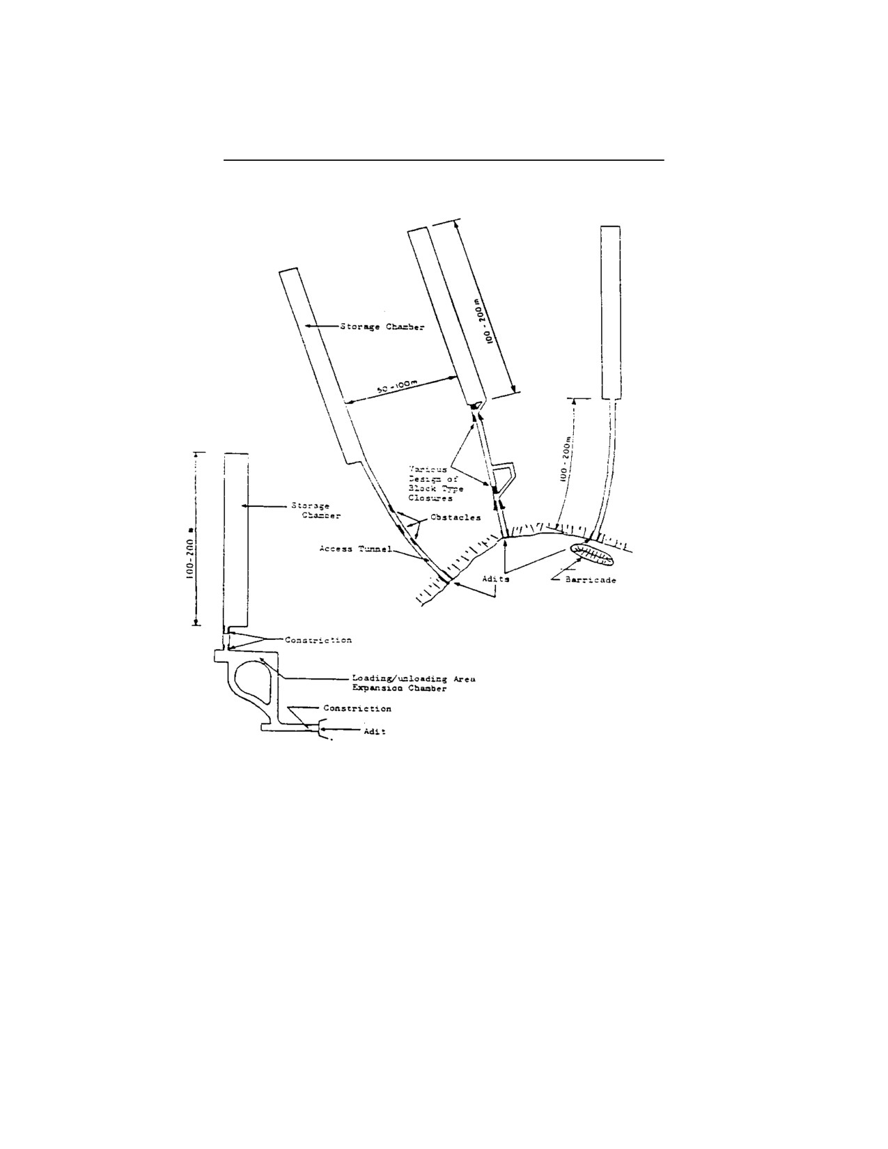
a)
Underground storage facilities may consist of a single chamber or a series of
connected chambers. The chamber(s) may be either excavated or natural
geological cavities. Figures 2-I and 2-II† illustrate general concepts for several
possible configurations of underground facilities. Underground ammunition
storage sites should be located in sound rock. A storage site may consist of
one or more storage chambers with usually one access tunnel in each
chamber. The number of chambers depends upon prevailing topographical
and geological circumstances and safety aspects in the environment of the
storage site. Potential blockage should be considered for multi-chamber sites.
b)
The thickness of the rock formation surrounding an underground storage site
should be designed so cratering hazards, in case of an explosion, can be
practically excluded. Then the only significant external hazards will be the
ground shock and the explosion effects coming from the adit tunnel. The
effects coming from the adit may be considerably reduced by means of
structural measures in or in front of the tunnel or even eliminated by the
installation of tunnel closing devices.
c)
Adequate separations and tunnel closing devices should be used to prevent
the propagation of an explosion from chamber-to-chamber.
d)
Provided the access openings are adequately hardened, underground storage
is relatively well-protected against enemy attack..
e)
Geological aspects have a great influence on building costs and, in terms of
the construction cost alone, underground storage is often more costly than
aboveground storage. However, when estate, operating, maintenance and
lifetime costs are considered, at least for larger underground facilities, it may
be less than for comparable aboveground facilities. Generally, the most
economical are chambers measuring from 100 to 200 m in length with a
volume between 5,000 and 15,000 m3. This provides a total gross capacity
between 1000 and 2000 tonnes of ammunition. The length of the access
tunnel may be 50 to 150 m, depending on topographical conditions and the
desired rock thickness.
† Figures are included in Text
NATO/PFP UNCLASSIFIED
-III-2-1-
Change 3

NATO/PFP UNCLASSIFIED
AASTP-1
(Edition 1)
Figure 2-I:
Layouts of Underground Facilities
Main Passageway
Extension
Storage Chamber
Branch
Passageway
Blast Door and
Blast Valve
Storage Chamber
Branch Passageway
Blast Door and
Blast Valve
Loading/Unloading dock
Main
Passageway
Adit
Barricade
Shot gun type
NATO/PFP UNCLASSIFIED
-III-2-2-
Change 3
NATO/PFP UNCLASSIFIED
AASTP-1
(Edition 1)
Figure 2-II:
Layouts of an Underground Storage Site
NATO/PFP UNCLASSIFIED
-III-2-3-
Change 3

NATO/PFP UNCLASSIFIED
AASTP-1
(Edition 1)
3.2.1.2. Explosion Effects in Underground Ammunition Storage Sites
a)
The blast wave originating from an explosion in an underground storage
chamber will surge through the rock formation as ground shock and will
escape as blast through the access tunnel into the open air. The strong
confining effect of an underground storage site and the large amount of hot
explosion gases generated will produce a relatively constant high pressure in
the chamber. This pressure may break up the rock formation and produce a
crater. The kinetic energy (dynamic pressure impulse) of the blast in the main
passageway is very high compared to an explosion in free air. Objects like
unexploded ordnance, rock, gravel, equipment, and vehicles will be picked up
and accelerated up to velocities of several hundred metres per second before
leaving through adits. In addition, engineered features can collapse and cause
debris hazards. Break-up of the cover will cause projection of a heavy fall of
rock and earth in all directions onto the surrounding surface area.
b)
The explosion gases will surge at a high velocity through the access tunnel
into the open air where they will burn completely. The escaping gases will
carry along ammunition, rock debris, installations, and lining onto surrounding
areas.
c)
A disturbance near the surface of the ground will emit compression P-waves,
shear S-waves, and Rayleigh surface R-waves in a semi-infinite elastic
medium. Deeply buried disturbances will emit only P-waves and S-waves, but
in the far field, interface effects will result in R-waves being produced. For all
of these waves types, the time interval between wave front arrivals becomes
greater and the amplitude of the oscillations becomes smaller with increasing
standoff distance from the source.
The first wave to arrive is the P-wave, the second the S-wave, and the third
the R-wave. The P-wave and S-wave are minor tremors, as these waves are
followed by a much larger oscillation when the R-wave arrives. The R-wave is
the major tremor because: 1) about two-thirds of the ground shock energy at
the source goes into the R-wave, and 2) the R-wave dissipates much less
rapidly with distance than either the less energetic P-wave or S-wave. P-
waves and S-waves dissipate with distance r to a power of r-1 to r-2. At the
surface, P-waves and S-waves dissipate with distance as r-2, while R-waves
dissipate with distance as r-0,5. The greater energies being transmitted by R-
waves and the slower geometric dissipation of this energy causes R-waves to
be the major tremor, the disturbance of primary importance for all
disturbances on the surface.
NATO/PFP UNCLASSIFIED
-III-2-4-
Change 3

NATO/PFP UNCLASSIFIED
AASTP-1
(Edition 1)
d)
Small-Scale Model Tests and Validity of Scaling Laws
1.
A portion of the blast energy from an underground detonation is used
to compress the surrounding geological media. This allocation of
energy should be considered when evaluating the experimental results
of underground tests.
2.
Small-scale, modeling tests that are constructed of non-responding
materials do not exhibit the non-linear energy loss effects typical of an
underground explosion. Therefore, air blast results from non-
responding models tend to be safety conservative for predicting
hazards that would occur in an actual underground event. In spite of
this, small-scale model tests are still of value for design purposes.
3.2.1.3. Advantages of Underground Storage
Advantages of underground storage are:
1.
A smaller total land area is required than for an aboveground storage.
2.
A high degree of protection is afforded against bombing or terrorist
attack.
3.
The area is easier to camouflage and to guard than an aboveground
area.
4.
In case of an incident in an underground chamber, damage to
ammunition in other chambers is preventable. Damage to ammunition
in aboveground buildings, other than earth-covered magazines, is
usually more extensive.
5.
The temperature in underground storage sites is almost constant. The
deleterious aging effects on munitions and explosives caused by
extreme temperatures and temperature cycling is mitigated.
6.
Effects of sand, snow, and ice, which may cause difficulties in
aboveground storage, may be avoided.
7.
Inherent protection may be afforded against external fire.
8.
Estate costs, as well as maintenance and operation may be less costly
as for an aboveground storage site, thus more than offsetting the
construction costs.
NATO/PFP UNCLASSIFIED
-III-2-5-
Change 3

NATO/PFP UNCLASSIFIED
AASTP-1
(Edition 1)
3.2.1.4. Disadvantages of Underground Storage
Disadvantages of underground storage may be:
1.
The choice of localities is restricted.
2.
The costs of the original excavation or the modification of an existing
excavation and the installation and maintenance of special equipment
may increase the initial costs of underground storage over that of
aboveground.
3.
Extra handling equipment may be required.
3.2.1.5. Work Prohibited in Underground Storage Sites
The opening of packages or the removal of components from unpacked
ammunition or similar operations should be prohibited in the storage chamber, but
could be done in the loading/unloading dock or in a separate chamber if suitable
measures are taken to prevent a propagation into the storage chambers.
3.2.1.6. Storage Limitations
Limitations on underground storage are:
1.
Ammunition containing Flammable Liquids or Gels
Ammunition containing flammable liquids is only permitted in
underground storage sites if proper protection against fuel leakage is
established. The possible energy release of a stochiometric
combustion should be considered as part of the total energy release.
Multi-chamber sites should be arranged and/or sealed in such a way
that fuel-fire or gas explosion should not increase the likelihood of
reaction in neighbouring chambers more than established through
interior distances to prevent detonation transfer.
2.
Ammunition containing Toxic Agents
Because of the difficulties of decontamination underground,
ammunition containing toxic agents should only be stored under
special provisions.
3.
Suspect Ammunition and Explosives
Suspect ammunition and explosives should not be stored.
NATO/PFP UNCLASSIFIED
-III-2-6-
Change 3

NATO/PFP UNCLASSIFIED
AASTP-1
(Edition 1)
4.
Ammunition containing Pyrotechnics
Ammunition containing pyrotechnics, such as illuminating, smoke and
signal ammunition, could in some cases be more vulnerable to
mishaps or self ignition, and thereby increase the likelihood of an
accident. The decision to store ammunition that contains pyrotechnics
underground must be made on a site-specific basis and provisions
must be taken to mitigate the peculiar hazards of pyrotechnic materials.
5.
Ammunition containing Depleted Uranium
Before ammunition containing depleted uranium is permitted in
underground sites, the slight radioactivity and chemical toxicity that
would result from an accidental fire or explosion should be assessed
and accepted.
NATO/PFP UNCLASSIFIED
-III-2-7-
Change 3

NATO/PFP UNCLASSIFIED
AASTP-1
(Edition 1)
Section II - Design
3.2.2.1. General
Planning of new underground storage facilities must account for site
conditions, storage requirements, and operational needs. Only when these are
established can the design be developed. An optimal compromise between the
sometimes-contradictory demands for planning, construction and operation of
storage sites must consider safety, military and cost requirements.
3.2.2.2. Safety Requirements
Operational procedures should be planned and conducted so that, to the
best extent possible, explosives mishaps are prevented. Facility configurations are to
be designed so that, if an explosives mishap should occur, its hazards are mitigated
to acceptable levels. Safety efforts that are essential for ammunition storage sites
include:
1.
Surveillance and maintenance to ensure that only safe ammunition is
stored
2.
Well-designed and environmentally controlled chambers and facilities
to protect the ammunition against unintended events
3.
Suitable structural designs and operating procedures
(doors and
guards, for example) to protect the ammunition against deliberate
action by third parties
4.
Structural designs and operating procedures to
a)
mitigate explosion propagation outside the area of initial
occurrence, and
b)
provide desired levels of personnel, facility, and asset protection
5.
The construction and operation of ammunition storage sites should
only be entrusted to qualified and trained personnel who have clearly
defined responsibilities.
6.
Evaluate a suitable location for the installation taking into account the
site-specific use of surrounding (inhabited buildings, roads, etc.).
NATO/PFP UNCLASSIFIED
-III-2-8-
Change 3

NATO/PFP UNCLASSIFIED
AASTP-1
(Edition 1)
3.2.2.3. Military Requirements
Functional requirements that dictate the geographical location of a storage
site or its storage and transfer capacity, may sometimes run counter to desirable
safety considerations, thereby requiring innovative designs to provide required levels
of explosives safety. Military requirements often involve protection against enemy
weapons, intruder protection, etc.
3.2.2.4. Financial Aspects
The lifetime cost of a storage facility
(construction, operation, and
maintenance) should be considered during the planning phase. Where possible,
designs should be selected that minimize total cost while providing required safety
and operational capabilities.
NATO/PFP UNCLASSIFIED
-III-2-9-
Change 3

NATO/PFP UNCLASSIFIED
AASTP-1
(Edition 1)
Section III - Equipment
3.2.3.1. Humidity Control and Ventilation
a)
High humidity may be a problem in underground sites. Dehumidifying
equipment may then be necessary to control relative humidity to 60%. Certain
types of ammunition may require lower relative humidity
(50%).
The
chambers may be lined with concrete or coated fabric to better control
humidity. The roof lining should be strong enough to withstand minor rock
falls.
b)
The type of transportation equipment used may govern ventilation
requirements. Ventilation shafts to the exterior should be designed to prevent
trespass and sabotage.
3.2.3.2. Electric Installations and Equipment
a)
Electric installations and equipment for underground storage sites should
conform to the national standards of the host nation.
b)
An emergency lighting system should be installed. Otherwise transportable
battery operated lights of an appropriate standard should be provided and
kept at suitable points.
c)
A portion of the personnel employed underground should be equipped with
hand lamps of an appropriate standard.
3.2.3.3. Lightning Protection
An underground storage site does not normally require a system of
protection against lightning. Metal and structural parts of the site which have less
than 0.6 m cover should be protected as for an aboveground site, see Part II,
Chapter
3, Section IV. However, each underground storage site should be
considered individually to take account of possible conducting faults in the cover.
3.2.3.4. Transport and Handling Equipment
Rail vehicles, road vehicles, mobile lifting or stacking appliances and cranes
of the fixed or gantry type, when operated electrically or by diesel engine, may be
permitted in underground storage sites subject to the following conditions:
NATO/PFP UNCLASSIFIED
-III-2-10-
Change 3

NATO/PFP UNCLASSIFIED
AASTP-1
(Edition 1)
1.
Electrical equipment should conform to the national standards of the
host nation for underground storage sites.
2.
Diesel operated equipment should be fitted with an effective means of
preventing sparks or flames from exhaust outlets. Any portion of the
exhaust system or exposed parts of the engine, which may develop a
surface temperature exceeding 100o C, should be suitably screened to
ensure that all exposed surfaces are below that temperature. If the
engine is to be kept running during loading and unloading within the
storage site, it should conform to the host nation standards for
underground (confined space) operations.
3.
The flash point of the fuel oil for diesel engines should be not less than
55o C. Fuel tanks should be filled only at authorized places and no
spare fuel should be carried.
4.
Where fuel oil filling stations are authorized in the underground area,
the fuel should be taken underground in strong closed containers in
quantities not exceeding that required for one working day. The filling
station should have a concrete floor with a sill of sufficient height to
contain the quantity of fuel authorized to be stored there.
3.2.3.5. Fire-fighting Equipment
Equipment should conform to the national standards of the host country with
particular consideration given to the following:
1.
Reduce the probability that a small fire will escalate by installing an
automatic smoke-detecting and fire-extinguishing system.
2.
Consideration should be given to protecting reserve water tanks from
potential explosives effects.
3.
An alarm system should be provided to operate throughout the whole
area, both above and below ground.
4.
In air-conditioned sites or in sites provided with forced ventilation, the
need to shut these down on an outbreak of fire must be considered.
5.
Fire-fighting equipment retained underground should be positioned for
accessibility and potential use.
6.
For large underground areas, detector devices, to specify the location
of a fire, and communication capabilities, to issue instruction
throughout the underground facility, should be installed.
NATO/PFP UNCLASSIFIED
-III-2-11-
Change 3

NATO/PFP UNCLASSIFIED
AASTP-1
(Edition 1)
7.
Self-contained breathing apparatus and training in its use are essential
for underground fire fighting or rescue operations, etc.
NATO/PFP UNCLASSIFIED
-III-2-12-
Change 3