Instruction Manual for Single Stage 350, 500, and 700 Frame Steam Turbines - page 4
Troubleshooting
No.
Symptom
Probable Cause
Corrective Action
1
Excessive
Misalignment.
Check the alignment when the turbine is hot.
vibration or
Disconnect coupling between turbine and driven
noise
machine; run the turbine alone. If the turbine
runs smoothly, there is either misalignment, a
worn coupling, or the driven equipment is at
fault. To check alignment, refer to Section C. If
the turbine drives a coupled gear, and the gears
run together at the top, allow for the pinion
running in the top of its bearing when under
load.
Worn bearings
Replace bearings. Refer to Section L.
Worn coupling to driven
Check condition of coupling. Replace if
machine.
necessary.
Glands fitted too tightly.
Tight carbon rings may cause vibration and
overheating. Refer to Shaft Packing Section for
proper clearance.
Loose wheels are extremely
Rotor should be returned to the factory to be
unusual, but may be caused by a
repaired.
runaway,
excessive
steam
temperature or shock loading.
Bent shaft
May be caused by hot bearings (see “Bearing
Heating and Wear”), tight glands (see “glands
Fitted too Tightly”), or mechanical damage.
Check the shaft runout near the center, as well
as at the shaft extension. Replace the shaft if
runout is excessive. Refer to Section L.
Unbalanced coupling to driven
Remove coupling halves and check for
machine
unbalance.
Unbalanced wheel
Check if turbine wheel has become unbalanced
due to fouling, over-speeding, or loss/damage to
shrouds or blades. Check if the turbine has been
standing idle for a long period without drainage
of the exhaust casing. Solid matter can build up
in the lower half of the wheel, causing
unbalance. The turbine wheel must be cleaned,
re-balanced or replaced. Refer to Section L.
Table K-1. Troubleshooting Guide
184
Troubleshooting
No.
Symptom
Probable Cause
Corrective Action
Piping strain
Both the inlet and exhaust steam lines should be
properly supported to prevent strains from being
imposed on the turbine. Sufficient allowance
should be made for thermal expansion. Refer to
Section C.
Excessive end play
Check the axial position of rotor. If the endplay
exceeds 0.020”, replace thrust bearing. Verify
that coupling is cleaned and installed properly
so that excessive thrust is not imposed on
turbine from driven equipment.
2
Bearing
Improper lubrication
Refer to Section F to verify that the proper
Failure
lubricant is being used. Check oil periodically to
ensure that it is free of condensate and sediment.
Improper water cooling
When water-cooling is required, the water flow
must be adjusted to maintain bearing oil sump
temperature in the normal range, as shown in
Table F-2.
Wear and/or scratches in sleeve
Replace the sleeve bearings, drain oil reservoirs,
bearing
clean bearing housings, and add new oil. Inspect
journal surfaces.
Rough or untrue thrust collars.
Rough or untrue thrust collars on single-stage
(shoe-type bearing)
machines may cause rapid wear on thrust
facings of the sleeve bearings. This could
eventually increase thrust clearance to a point
where the turbine wheels would rub on the
guide or reversing ring. Rough or untrue collars
should be replaced or repaired at the first
opportunity.
Misalignment
Misalignment is one of the common causes of
bearing failure. Refer to remedies for
Misalignment under Vibration above.
Table K-1. Troubleshooting Guide (Cont.)
185

Troubleshooting
No.
Symptom
Probable Cause
Corrective Action
Bearing fit
Ball bearings should fit on the turbine shaft with
a light press fit. Too tight a fit can cause
cramping; too loose a fit will allow the inner race
to turn on the shaft. Either condition results in
wear, vibration, overheating, and ultimate
bearing failure. Replace the shaft if worn below
recommended or specified size. Refer to Section
L.
Excessive thrust
Verify that the coupling is clean and is installed
so that excessive thrust is not imposed on the
turbine from the driven equipment. If a fairly
high thrust is imposed on the turbine, consult the
factory to determine whether the thrust bearing is
suitable for the application.
Excessive belt pull
On belt driven units, verify that belts are not too
tight and consult the factory to determine
whether the turbine bearing is suitable for the
application.
Unbalance
Refer to Unbalanced Wheel under Vibration
above. Unbalance can cause excessive bearing
wear and early failure.
Excessive tension
in
The tension on the speed changer spring must be
spring
type
speed
sufficient to hold the governor lever firmly
changer.
against the governor spindle connection under all
conditions. Avoid any unnecessary loading on
this spring, as this would impose excessive load
on the thrust bearing.
Speed governor trying to
Leaking or stuck valve should be corrected, as it
close a leaking or stuck
constitutes a safety hazard, besides being
governor valve.
detrimental to the thrust bearing. Excessive wear
is also imposed on the governor ball thrust
bearing.
Heavy slugs of water in
This condition can be avoided through proper
the steam.
boiler control. Damage to the thrust bearings
and wheels will result from water slugs.
Table K-1. Troubleshooting Guide (Cont.)
186
Troubleshooting
No.
Symptom
Probable Cause
Corrective Action
Rust
Rust may develop on bearing surfaces when the
turbine is improperly stored; refer to Section A
for details. Rust may also develop when the
turbine is out of service for long periods, without
receiving proper attention; refer to Section J.
3
Excessive steam
Dirt under rings
Steam leaking under carbon rings may carry
leakage past shaft seals
scale or dirt, which can foul the rings. Remove
rings and clean, as per Section L. The rings
should be free to float axially, and the
downstream face of the ring must seat perfectly
against the smooth, true and clean surface of the
adjacent carbon ring spacer.
Shaft scored
The shaft surface under carbon rings must be
smooth to prevent leakage. Factory-supplied
shafts are hard chrome plated. Polish minor shaft
imperfections or replace the shaft, per Section L.
Worn or broken carbon
Replace with new carbon rings, as per Section L.
rings
Although there are
3 segments per ring, the
entire ring must be replaced. Carbon rings
should have a slight clearance on the shaft when
cold, as carbon expands much less with heat than
steel.
Corroded, worn or dirty
Steam will leak past the carbon ring partition
partition plate surfaces
surface if dirt, corrosion or scoring prevents a
good seal. Polish sealing surfaces. Replace
partitions (when used) if badly worn or pitted.
Refer to Section L.
Labyrinth steam seal
Refer to Sections L and Supplemental Data for
improperly installed
proper installation procedure.
Worn or broken labyrinth
Replace labyrinths. Refer to Sections L and
steam seal teeth
Supplemental Data for proper installation
procedure.
Excessive
exhaust
Packing cases are designed for a pre-determined
pressure
backpressure. Excessive backpressure causes
leakage, which is a common cause of water in
the lubricating oil.
Excessive joint sealing
When replacing carbon rings, use joint
compound in gland
compound sparingly. Excess compound may
housing
foul carbon rings and gland housing sealing
surfaces.
187
Troubleshooting
Table K-1. Troubleshooting Guide (Cont.)
No.
Symptom
Probable Cause
Corrective Action
Leak-off pipe plugged
Verify that all steam and condensate can
discharge freely. Refer to Section C.3.10.
4
Oil leaks past laby seal
High oil level
Reduce the oil level to coincide with marks on
bearing housings. Refer to Section F.
Scratched or rough shaft
Polish the shaft under the laby seal and install a
under laby seal
new laby seal. Refer to Sections F and L.
Seal improperly installed
Refer to Sections F and L for proper installation
procedure.
Shaft vibration
Refer to all causes under Vibration above. Install
a new laby seal, if necessary, as per Sections F
and L.
5
Insufficient
power
Too many hand-valves
Open additional hand-valves. Refer to Section I
(turbine does not run at
closed
for proper adjustment of hand-valves.
rated speed)
Oil relay governor set too
Refer to Section D for speed adjustment and
low
speed range limits.
Inlet steam pressure too
Check the steam pressure at the turbine inlet and
low or exhaust pressure
exhaust pressure close to the exhaust casing,
too high
using accurate gauges. Refer to the turbine
nameplate for intended steam conditions. Low
inlet pressure may be the result of auxiliary
control equipment such as a pump governor
which is too small, improper piping size,
excessive piping length, etc.
Load higher than turbine
Determine the actual load requirements of the
rating
driven equipment. In some instances, modifying
a few components can increase available turbine
power. Consult the factory for this
determination.
Throttle
valve
not
Close the main inlet valve and disconnect throttle
opening fully
linkage. The valve lever should move freely
from fully open to fully closed. If not,
disassemble the throttle per Section L and free
up the assembly, as required.
Low governor oil level
Refill—Refer to Section D.
188
Troubleshooting
Table K-1. Troubleshooting Guide (Cont.)
No.
Symptom
Probable Cause
Corrective Action
Nozzles plugged
Remove the cover and rotor and inspect nozzle
openings. Remove nozzle block to clean nozzles
as required.
Steam strainer
Remove all foreign matter from steam strainer.
Refer to Section L.
6
Speed increases
Throttle valve not closing
Refer to governor valve not opening fully under
excessively as load is
fully, governor responds
Insufficient power above. Free the sticking valve
decreased
slowly due to worn parts
and inspect all pivot points in linkage for signs
or sticking.
of sticking or binding or excessive wear.
Throttle valve and valve
Remove governor valve, as per Section L. Check
seats cut or worn
valve and seats for wear or steam cutting.
Replace if necessary.
7
Excessive speed
Governor
droop
An increase in the internal droop setting will
variation
adjustment
reduce speed variation or hunting. Refer to
Droop Adjustment in the Woodward Governor
Manual.
Governor lubrication
Low governor oil level, or dirty or foamy oil
may cause poor governor operation. Drain, flush,
and refill governor with the proper oil. Refer to
Section D.
Governor valve assembly
Disassemble the governor valve per Section L.
friction
Inspect for free and smooth movement of all
moving parts. If required, polish throttle valve,
governor valve and bushing assembly, and valve
stem with very fine Emery cloth. Inspect valve
stem for straightness and for build-up of foreign
material. Replace components as required.
Governor valve seal
Check the valve stem for free and smooth motion
friction
through the throttle bonnet assembly. If friction
or binding occurs, disassemble throttle bonnet
assembly and repair or replace seal components,
as necessary. Refer to Section L.
Rapidly changing load
Rapidly changing load can sometimes cause
governor hunting. Consult the factory, providing
details of the application.
189
Troubleshooting
Table K-1. Troubleshooting Guide (Cont.)
No.
Symptom
Probable Cause
Corrective Action
Governor knife edges
These must be replaced if badly worn. There is
worn.
no effective repair for these parts.
Lost motion so the
This is usually the result of excessive wear at the
governor valve does not
pivot points in the linkage. Bearing in the
always follow the motion
linkage should be replaces, as well as the linkage
of the governor.
pins.
Light load and high inlet
In some cases, where the turbine provides a large
steam pressure
amount of reserve power and the inlet steam
pressure is quite high, there is a tendency for
excessive speed variation. Try operating the
turbine with additional hand-valves closed. This
condition can sometimes be corrected by
replacing the governor valve and bushing
assembly. Consult the factory, providing details
of the application.
8
Sluggish governor
Governor
droop
Reduce the droop setting. Refer to Droop
response.
adjustment
Adjustment in Woodward Governor Manual.
Turbine carrying very
Open necessary hand-valves to increase
heavy load, little reserve
horsepower.
power.
9
Slow start-up
General
Refer to all causes under Insufficient power
above.
High starting torque of
Obtain the required starting torque from the
driven equipment
driven equipment manufacturer and consult the
factory to determine whether the turbine is
overloaded in the application.
10
Governor not operating
Governor valve travel
Refer to Governor valve not opening fully under
restricted
Insufficient power above.
190
Troubleshooting
No governor control on
If the speed increases continuously on start up
start-up
and the governor does not close the throttle
valve, the governor pump may be installed in the
wrong direction of rotation. Also verify that the
installed governor operates in the proposed speed
range. If pump rotation appears to be the
problem, remove the governor according to
Section L. Replace it with a governor of the
proper rotation. Refer to the Woodward
Governor Manual for instructions on changing
governor rotation or consult the factory.
Table K-1. Troubleshooting Guide (Cont.)
No.
Symptom
Probable Cause
Corrective Action
11
Governor oil leakage
General
Isolate the source of leakage. If leakage is at the
cover plate gasket, drain plug or oil breather,
replace the gasket and/or tighten these
components to stop the leak. If leakage occurs at
terminal shaft seals or the drive shaft seal,
replace the governor per Section L.
Drive assembly vibration
Vibration of the turbine shaft or governor drive
coupling may induce leakage at the governor
drive shaft seal. Refer to all causes under
Excessive vibration or noise above. Inspect and
tighten the coupling per Section L. Check for
misalignment or bent turbine or governor shaft.
12
Overspeed trip actuates
Overspeed trip set too
The over-speed trip should be set at
on load changes
close to turbine operating
approximately
16% OR 21% above the rated
speed
speed, depending on the NEMA rating (D or A)
of the governor. Refer to Section E.
General
Refer to all causes under Speed increases
excessively as load is decreased above.
Light load and high inlet
Refer to Light load and high inlet steam pressure
steam pressure
under Excessive speed variation above.
13
Overspeed trip actuates
Excessive vibration
Replace the trip lever and/or trip latch if latching
at normal operating
surfaces are worn, after resolving cause of
speed
excessive vibration.
191
Troubleshooting
Trip speed setting too
If the turbine consistently trips at or close to the
low
same speed, the trip setting may be set too low.
The setting should be approximately 16% OR
21% over rated speed, depending on the NEMA
rating (D or A) of the governor. Refer to Section
E for adjustment procedures.
14
Overspeed trip does not
Trip speed setting too
If the overspeed trip has not actuated when the
actuate at overspeed
high
turbine reaches 25% above rated speed, the trip
speed setting may be too high. The setting should
be approximately
16% OR 21% over rated
speed, depending on the NEMA rating (D or A)
of the governor. Refer to Section E for
adjustment procedures.
Table K-1. Troubleshooting Guide (Cont.)
No.
Symptom
Probable Cause
Corrective Action
Overspeed cup
Examine mechanism. Verify that it is clean and
mechanism
in good working order, and that the trip weight
can be moved easily by a small screwdriver or
similar tool.
Improper adjustment or
The trip valve must be tested frequently. To test
poor condition of the
the valve, trip the over-speed mechanism by
tripping
mechanism,
hand. Make sure the trip valve closes promptly
springs or latches.
and stops the turbine.
Excessive friction in trip
These serious faults should be corrected by
valve spindle packing.
cleaning, repairing or replacing parts so that this
Scaling,
wear,
or
important safety device can operate effectively.
mechanical damages in
trip valve or its supports.
Governor does not trip at
Gain access to and examine the overspeed
or near the proper speed.
governor. Make sure it is clean, in good order,
and that the emergency weight can be easily and
freely moved in the governor cup by a small
screwdriver or similar tool. Adjust as described
in Section VI. Test the unit by actually over-
speeding. If it still does not trip at the proper
speed, adjust the setting of the emergency
governor as required. If low oil pressure trips,
solenoid trips, high back pressure trips, or similar
devices are provided, check them at the same
time.
192
Troubleshooting
Overspeed trip valve
Overspeed trip valve may be frozen in place due
unable to close
to steam deposits, corrosion, or other
contaminants. Disassemble and clean valve
assembly according to Section L.
A broken steam strainer, or other foreign objects,
may interfere with proper seating of the over-
speed trip valve. Disassemble and inspect
combination valve according to Section L.
15
Excessive steam
Load
greater
than
The operator, after acquainting himself with the
consumption.
realized.
correct hand valve use on the turbine, must make
sure the correct combinations of hand valves are
open for various loads.
Table K-1. Troubleshooting Guide (Cont.)
No.
Symptom
Probable Cause
Corrective Action
Speed below normal.
Check the steam pressure and backpressure. Make
sure the governor is fully opening the valve. Check
and see if the hand valves are in use as designed.
Too many hand valves
This situation gives a turbine excessive capacity
open.
which requires throttling by the governor valve to
maintain the proper speed. This is inefficient and
uses more steam than necessary. Close the hand
valves to eliminate throttling.
Steam pressure low, or
These conditions must be corrected if the turbine is
exhaust pressure too
to carry a full load. Better boiler control will
high.
provide steam pressure correction. Horsepower
goes down as exhaust pressure goes up over
designed pressure.
Steam is wet, or the
This condition not only causes loss of power, but
super- heat low.
also is dangerous since it causes excessive erosion
on the nozzles and blades. Adjust steam conditions
as per manufacturer's recommendations.
Worn or damaged
This adversely affects the efficiency of the turbine.
nozzles and blades.
Nozzles and/or blades should be replaced or
repaired at the earliest opportunity.
Table K-1. Troubleshooting Guide (Cont.)
Refer
to
the certified drawings and the appropriate vendor manual for
Troubleshooting Guidelines for optional equipment.
193
THIS PAGE WAS LEFT BLANK
INTENTIONALLY
194
Section L
Disassembly and Parts Replacement
L.1 Warnings/Cautions
DANGERS
DO NOT attempt to ADJUST, REPAIR, DISASSEMBLE OR
MODIFY this turbine WHILE IT IS IN OPERATION, unless such
action is expressly described in this instruction manual.
NEVER DISCONNECT INLET OR EXHAUST FLANGES of the
turbine without first isolating the turbine from inlet and exhaust
systems by CLOSING AND TAGGING ISOLATING VALVES
and de-pressurizing the turbine casing and steam chest by
opening all drains. Open connections not protected by isolating
valves should be covered with blank flanges.
Do not remove any covers, guards, gland housings, drain
covers, etc. while the unit is operating.
WARNING
After operating the turbine, allow sufficient time for the turbine
to cool down prior to performing inspection, repair or
maintenance functions.
195
CAUTION
Do not operate the turbine above Maximum Continuous Speed
or below the Minimum Allowable Speed as shown on the
nameplate, for sustained periods of time.
WARNINGS
Modification of, incorrect repair of, or use of non-DRESSER-
RAND repair parts on this turbine could result in serious
malfunction or explosion that could result in serious injury or
death. Such actions will also invalidate ATEX Directive &
Machinery Directive Certifications for turbines that are in
compliance with European Directives. Refer to Section M -
Replacement Parts/Factory Service
NEVER REPLACE ANY ORIGINALLY SUPPLIED BOLT WITH
A SUBSTITUTE BOLT OF UNKNOWN or LESSER GRADE.
DO NOT MIX BOLTS during disassembly. Failure to use the
proper grade bolt could result in SERIOUS FAILURE of
pressure-containing components. Refer to Section B, Technical
Data.
MAINTENANCE PERSONNEL should be THOROUGHLY
FAMILIAR with the TURBINE AND ITS CONTROLS AND
ACCESSORIES, before attempting any maintenance or
service. A complete reading of this manual is recommended.
196

CAUTIONS
If the turbine is equipped with a throttle valve manufactured by
a party other than Dresser-Rand refer to Appendix B for
installation, operation, repair, and maintenance instructions.
If the turbine is equipped with a trip valve manufactured by a
party other than Dresser-Rand refer to Appendix B f this
manual for installation, operation, repair and maintenance
instructions.
WARNINGS
Dresser-Rand turbine components are manufactured from a
variety of materials, depending on steam pressure, steam
temperature, speed and horsepower. Before replacing any
components, be absolutely certain that the REPLACEMENT
PART was INTENDED for use in the TURBINE UNDER
REPAIR.
When RESTARTING a turbine after repair, maintenance or
rebuilding, always TREAT the turbine as if it were a NEW
TURBINE being started for the first time. Refer to Section I,
Start-Up and Operation.
CAUTION
CLEANLINESS is ESSENTIAL for long, trouble-free service
from BEARINGS and the GOVERNOR. Take care to ensure
that no foreign material enters bearing housings, the governor
or constant level oilers when performing maintenance, checking
oil, adding oil, or making adjustments.
L.2
General
This section describes disassembly and parts replacement for Dresser-Rand SST
turbines. Some parts of a SST turbine can be replaced in the field using instructions
197
presented in this section, if qualified personnel and facilities are available. If not, it
is recommended that a Dresser-Rand service representative be employed to make
the field repairs, or that the turbine be returned to the factory, where a complete
inspection can be made. If returned, the factory will prepare an estimate of the cost
of cleaning the turbine, replacing parts as required and restoring the turbine to
practically new condition. After factory repair, the turbine will be no-load tested
and preserved just as a new machine would be. A factory-rebuilt turbine receives a
new turbine warranty.
L.3
Turbine Case Upper Half Removal and Replacement
The upper half of the turbine case must be removed to gain access to the shaft
packing and turbine rotor. NOTE: Make sure that the steam inlet and the exhaust
line shut-off valves are shut before starting work.
In some applications, special bolting is supplied. Consult the factory before
replacing or torquing the bolts in the turbine.
WARNING
NEVER REPLACE THE ORIGINALLY SUPPLIED BOLT WITH
A SUBSTITUTE BOLT OF UNKNOWN or LESSER GRADE.
DO NOT MIX BOLTS during disassembly. Failure to use the
proper grade bolt could result in serious failure of pressure-
containing components.
If the applicable bolt torque is not specified in the Assembly/Disassembly section,
the following table may be used as a guideline.
The procedure for removing and replacing the case upper half is specified below.
Refer to the following figures:
L-1
Case Upper Half Removal
L-2
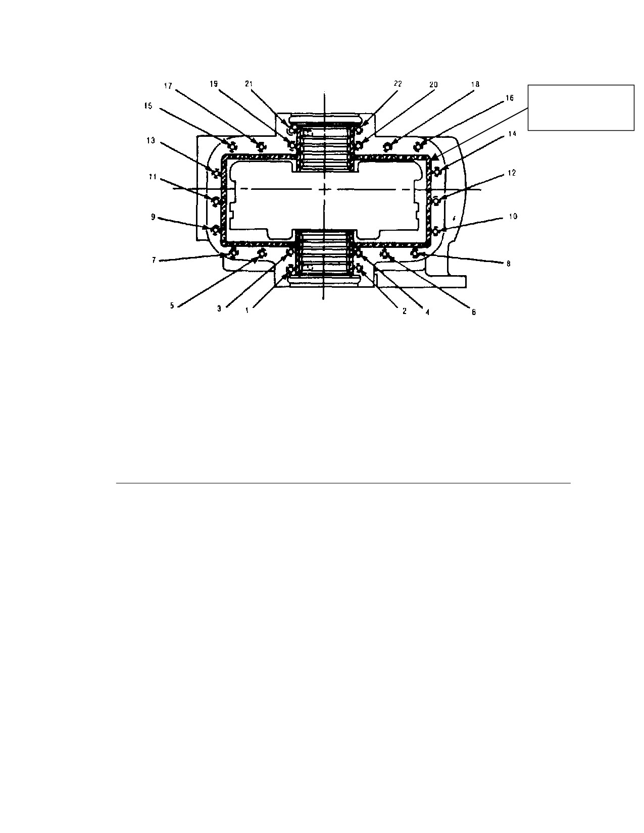
Flange Bolt Torque Sequence
L-3
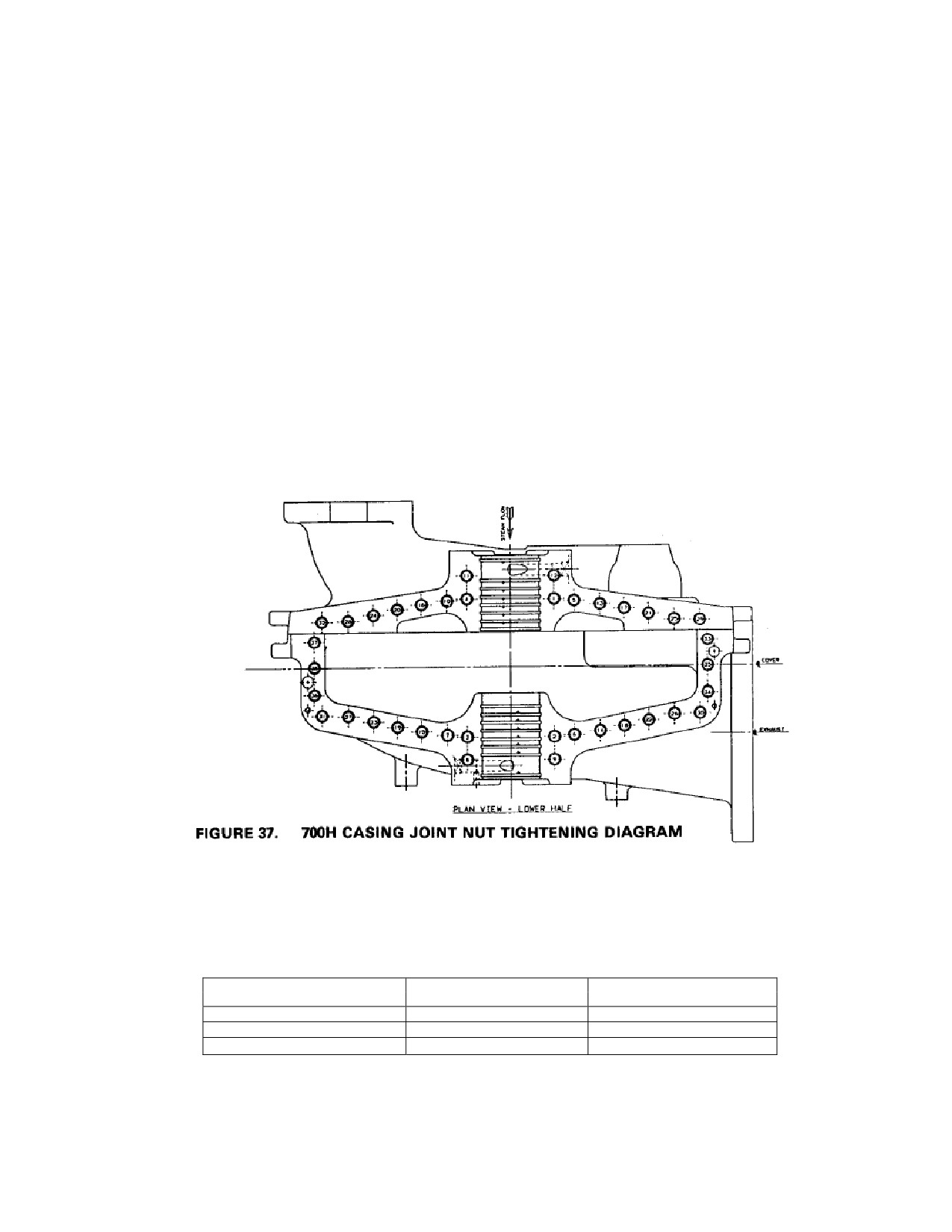
Flange Bolt Torque Sequence, 700H Casing
L-9
Hand Valve Assembly
M-8
Case, Rotor and Mechanical Gland Seals
M-9
Case, Rotor and Carbon Ring Gland Seals
Turbine Cover Removal (Upper half of the exhaust casing)
a. Remove the bolts from the horizontal flange of the turbine.
198
b. Break horizontal joint (cover/case mating surfaces) by inserting jacking bolts
in holes provided at the four corners of the cover flange.
c. Using a hoist and center eyebolt at the top of the upper case half, lift turbine
cover slowly and carefully so as to avoid damaging the rotor inside. Refer to
Figure L-1 Case, Upper-Half, Removal.
Place turbine cover on a clean surface so as to prevent damage to its sealing
face.
Figure L-1. Case Upper-Half Removal
Turbine Cover Replacement (Upper half of the exhaust casing)
a. Inspect the interior of the turbine cover and exhaust casing. Remove any
foreign material.
b. Remove all old sealant from both surfaces of the horizontal joint. Do not file,
gouge or scratch these surfaces. If the surfaces are warped, steam-cut or
otherwise damaged, a leak-tight seal may not be possible.
c. Apply joint sealant after cleaning the split surface on case and cover. Apply a
light coat of Hylomar (recommended by Dresser-Rand) to sit for 15 minutes
before putting the cover on the case.
199
Exhaust End
200
Approximate
location if string or
tape is used
Steam End
Figure L-2. Flange Bolt Torque Sequence
TORQUE — STUDS AND STUD BOLTS
TORQUE VALUES BELOW ARE TO ATTAIN APPROXIMATELY 45,000 PSI STUD
STRESS
SIZE
THREADS PER INCH
TORQUE (FT.•LBS.)
0.500
13
53
0.625
11
106
0.750
10
188
0.875
9
303
1.000
8
455
Table L-1. Applied Bolt Torques for Case Flange Bolts
1. After the joint is properly prepared, the threads that protrude through the flange
should be lightly coated with a thread lube/anti-seize compound.
2. Tighten all nuts in the sequence shown to approximately 50 percent of the
specified torque for the first pass and to the full torque value for a second and
third pass.
3. Check and, if required, retighten after the turbine is at normal operating
temperature using the sequence shown.
201
d. Apply anti-galling thread lubricant to the threads of all bolts.
e. Lower turbine cover onto lower half of casing. Ensure the cover seats evenly.
f.
Install and tighten the horizontal flange bolts in accordance with Figure L-2,
Flange Bolt Torque Sequence and Table L-1, Applied Bolt Torques for Case
Flange Bolts. Tighten all nuts uniformly to approximately 10% of the specified
torque; then using the illustration as a guide, tighten to full torque. Check and
re-tighten after turbine is at normal operating temperature, using the sequence
shown.
g. For the SST 700H casing, tighten all bolts in sequence indicated in Figure L-3
to level 1, and then repeat the sequence at level 2, and then at level 3 indicated
in table L-2.
Figure L-3. Flange Bolt Torque Sequence, Series 700H
BOLTS
BOLTS
#1-#24
#25-#38
FIRST PASS
2601-FT-LBS
2001-FT-LBS
SECOND PASS
5251-FT-LBS
4001-FT-LBS
THIRD PASS
5251-FT-LBS
4001-FT-LBS
Table L-2. Applied Bolt Torques Case Flange Bolts
202
h. Complete installing flange bolts using the sequence in Figure L-3 and the
applied torques in Table L-2.
i.
After the turbine is completely re-assembled and the coupling is made up, it
should be brought up to operating temperature and the bolts checked again.
There should be no slacking off of the bolts as a result of heating and cooling.
j.
When removing or replacing the top half of the casing, great care must be
exercised to avoid damage.
L.4
Carbon Ring Removal and Replacement
L.4.1
Carbon Ring Removal
Refer to the following figures:
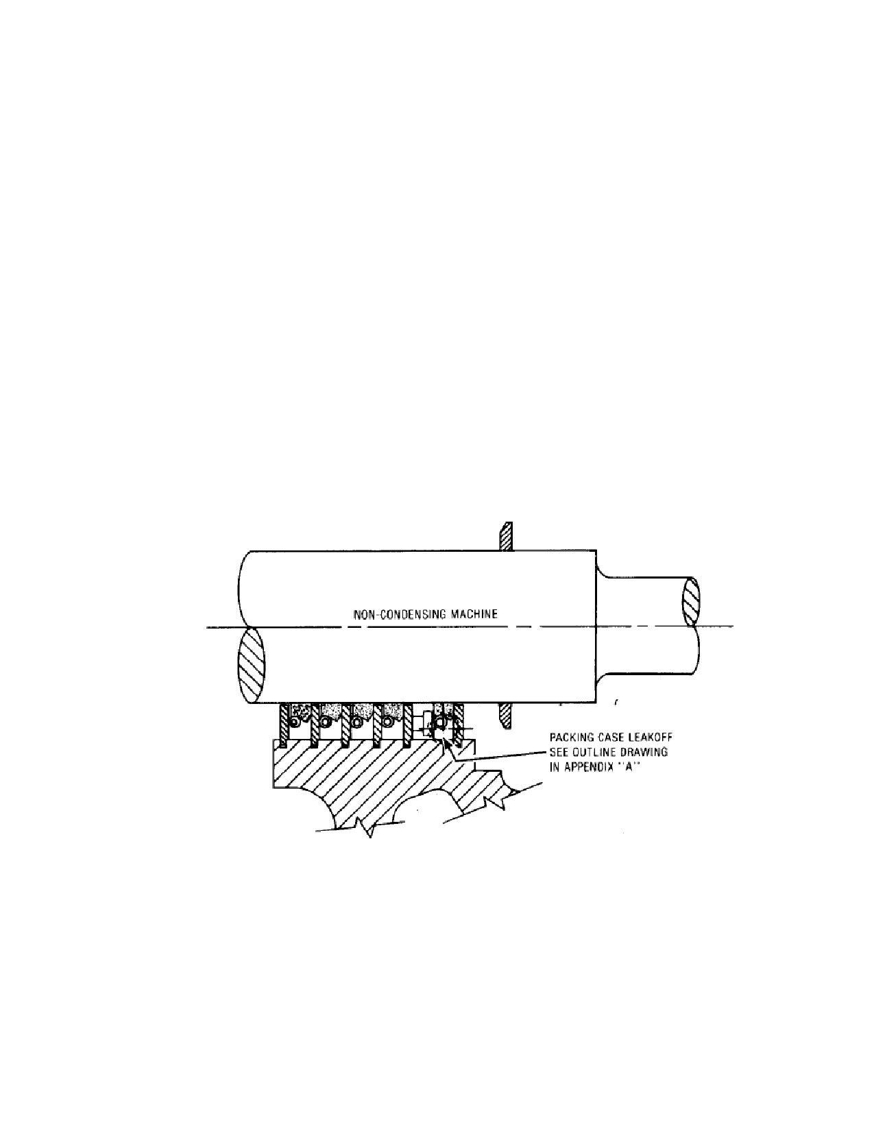
L-4
Carbon Ring Assembly, Non-Condensing Turbine
L-5
Carbon Ring Assembly, Condensing Turbine
Figure L-4 Carbon Ring Assembly, Non-Condensing Turbine
When removing the packing rings, be sure to keep each ring by itself. Note that the
ring segments are marked; these marks should be placed together when fitting or
replacing the rings in the turbine. When gland leakage indicates the necessity of
packing ring maintenance, it is recommended that new rings be installed.
203
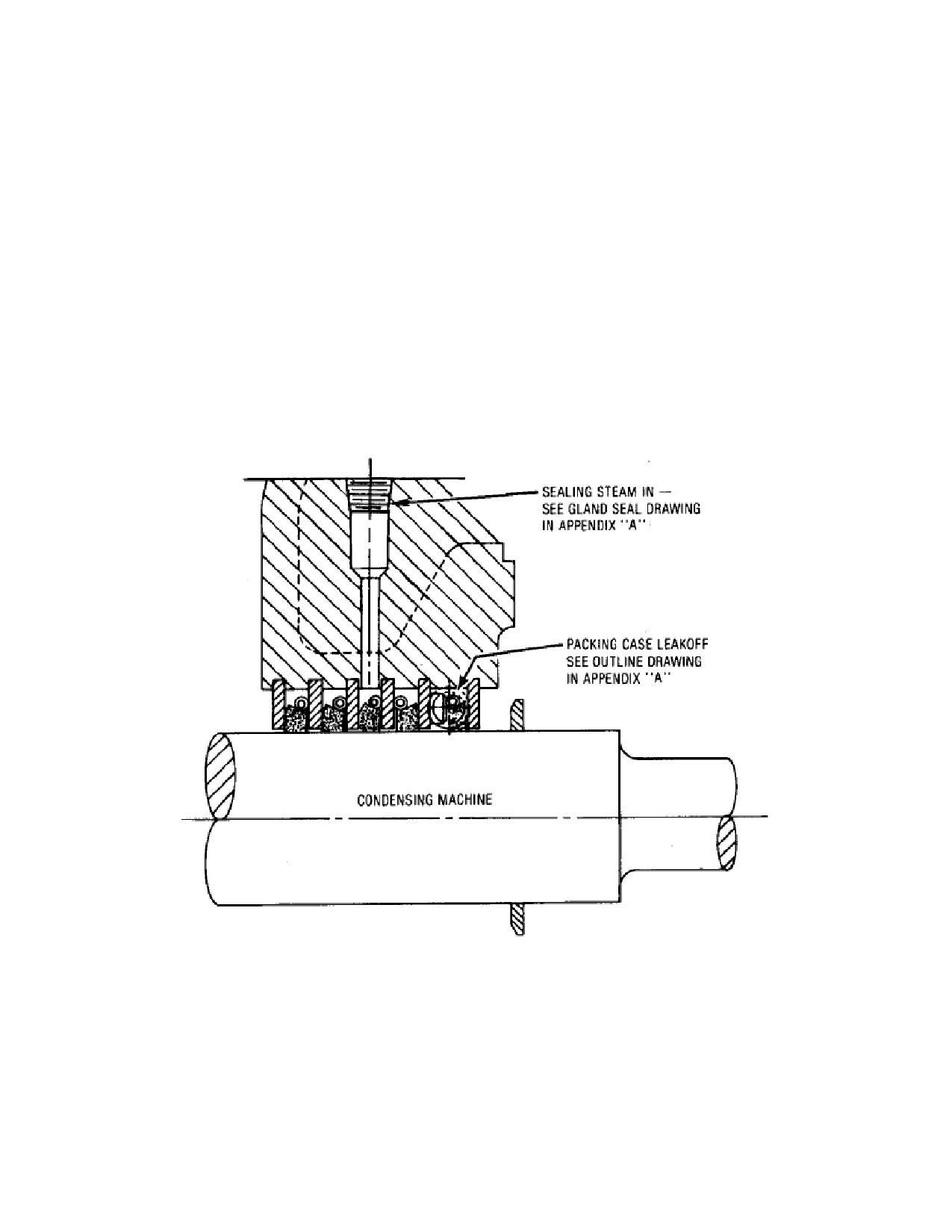
New packing rings furnished by Dresser-Rand will be made with the correct
diametral clearance, based on the original contract steam conditions. A packing
ring diagram, EW-33275 located in Appendix A, shows the part number and
location of each ring in the turbine.
When it is necessary to refit old rings (due to emergency condition) remove a small
amount, approximately
0.001”/0.025 mm from the ends of each segment,
maintaining flat square ends. The diametral clearance between the carbon rings
and the shaft should be as specified in the Packing Ring Diagram.
When installing new rings, the shaft surface should be smooth and highly polished,
clean and free of dust, water or oil. The spacer rings should be clean and smooth
with a true surface. If the sealing surface of the spacer ring is warped, the carbon
ring cannot seal. Warped spacer rings should be replaces. To install new carbon
rings, see Figure L-6 for procedure.
Figure L-5 Carbon Ring Assembly, Condensing Turbine
a. If there is a leak-off connected to the cover disconnect this and remove the
pipe from the cover.
204
b. Remove turbine cover according to the procedure specified in Section L.3.1.
c. Disconnect the garter spring ends. Remove the garter springs and carbon ring
segments. Note that the anti-rotation pin in the packing case may interfere
with carbon ring segment removal. If so, simply rotate the segment in the
opposite direction, or rotate the partition plate.
d. Inspect and clean the spacer rings. If the spacer rings are damaged they should
be replaced. The shaft will have to be removed. Refer to Section L.9 Rotor
and Turbine Wheel Removal and Replacement.
e. Clean the stainless steel high velocity oxy fuel-coated surfaces of the shaft
with stainless steel high velocity oxy fuel spray. Inspect the stainless steel
plating. If plating is bubbled, split or peeling the shaft must be replaced.
L.4.2 Carbon Ring Replacement
a. Thread the garter springs into the slots between the spacer rings.
b. Install the carbon ring set one complete set at a time. Be certain to maintain
the correct relationship between carbon ring segments by matching dots
stamped on each segment. Dots should face toward the wheel. The anti-
rotation notch must engage the anti rotation pin.
c. Connect the garter springs to retain the carbon rings.
d. Replace the turbine cover per Section L.3.1.
205
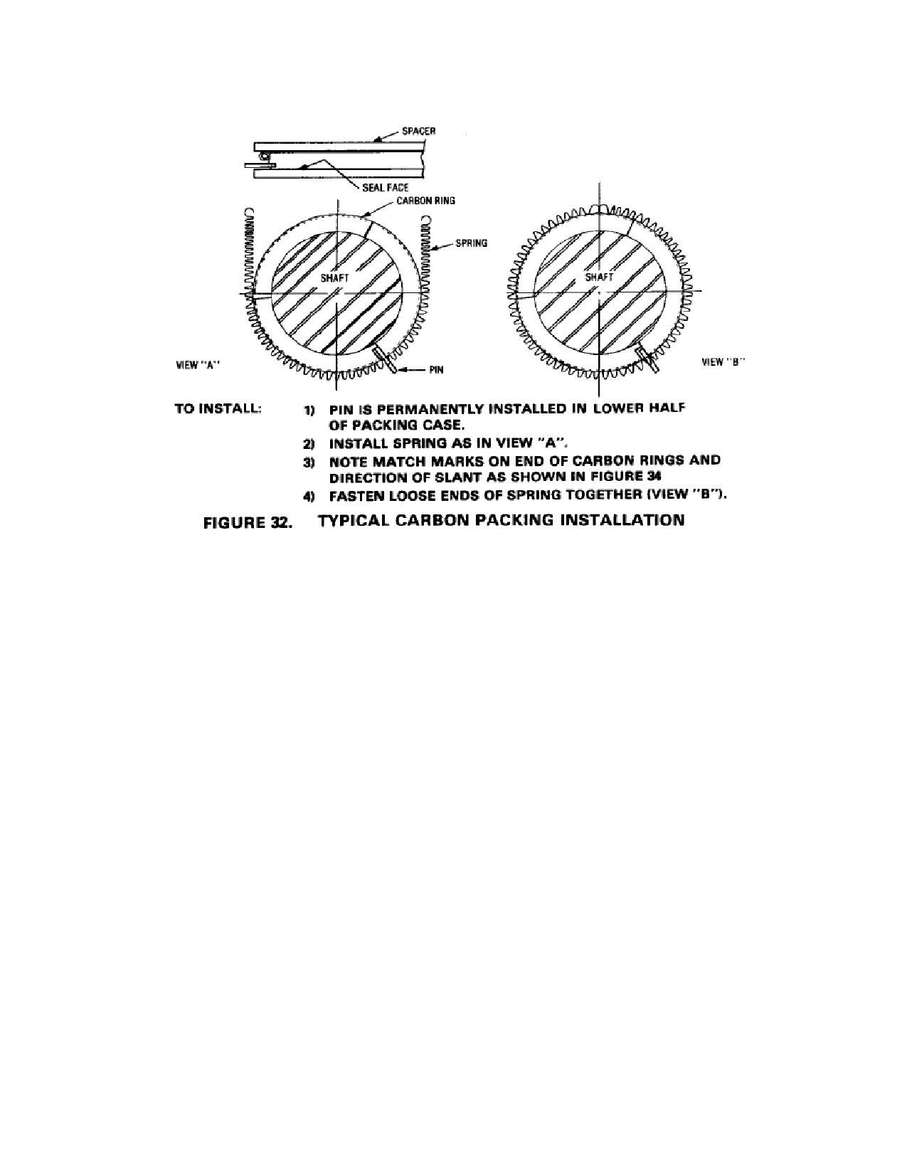
Figure L-6. Typical Carbon Packing Installation
L.5
Casing Labyrinth Seal Removal and Replacement
No field repairs of labyrinth are recommended. Slight deposits of the labyrinth on
the turbine shaft is an acceptable condition.
When installing new labyrinth rings, polish the shaft clean to remove any deposits
which may have formed.
Make sure that the quadrants of each ring are matched and that the rings are
installed in their proper position as identified in the packing ring diagram, EW-
33275. On installation of each quadrant of a gland-packing ring, make sure a
compression ring is installed in each hole. (See Figure L-7)
All SST turbine designs require removal of the turbine cover to remove, inspect,
and replace labyrinth seals. Refer to the appropriate section below to service these
labyrinth seals.
L.5.1
Casing Labyrinth Seal Removal
206
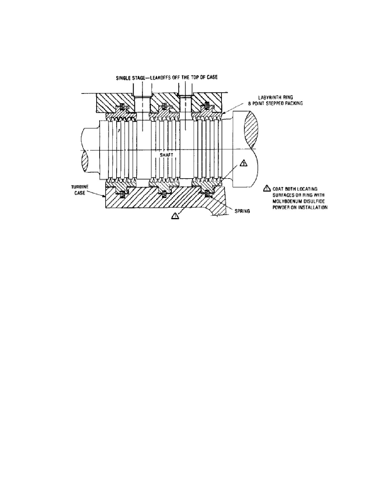
Refer to the following figure:
L-7 Labyrinth Seal Assembly
a. Remove the turbine cover according to the procedure specified in Section
L.3.1. The labyrinth seal segment(s) in the cover will be removed during this
operation.
b. Remove leak-off piping before removal of seals.
c. Inspect labyrinth seal segments, locating springs, and the shaft for corrosion,
scoring, or other damage. Clean all components. Replace any part that is no
longer serviceable. Labyrinth seal segments must be replaced as a set. Severe
rubbing one side of all labyrinth teeth may indicate a worn or failed thrust
bearing. Refer to Section L.6.2, Thrust Bearing Removal and Replacement, if
the thrust bearing is suspect.
L.5.1
Casing Labyrinth Seal Replacement
a. Install labyrinth seal segments into the lower half casing by rotating them
between the shaft and casing. Install the locating springs in the depressions, in
the segment and compress the springs as the segment is rotated.
207
b. Install the labyrinth seal segments into the seal housing lower half with
springs. Note that the labyrinth seal segments are matched-marked. Insure
that they are installed with their match-marks next to each other.
c. Install the labyrinth seal segments and springs in the seal housing upper half.
d. Replace the turbine cover and gland-housing cap according to the procedure
specified in Section L.3.1.
L.6
Turbine Bearing Removal and Replacement
SST turbines can be supplied with two, split sleeve journal bearings and one ball
thrust bearing. Shaft journal and bearing dimensions are shown on the turbine data
sheets. When running clearance is excessive, the bearings should be replaced not
re-babbitted. Approximately 0.004”/0.101mm over the maximum clearance is
considered excessive. However, if conditions permit and the unit runs smoothly,
bearings may be kept in service when clearances exceed the recommended
maximum clearance. It is left up to the discretion of the operating engineer as to
when bearing replacement is necessary. The bearings are longitudinally split to
permit removal and installation without removing the shaft.
Refer to the following figures:
M-4
Bearing Housing Assembly, Exhaust End Simple Bearing Case
M-5
Bearing Housing Assembly, Exhaust End Hi Cap Bearing Case
M-6
Bearing Housing Assembly, Non-Drive End Simple Bearing Case
M-7
Bearing Housing Assembly, Non-Drive End Hi Cap Bearing Case
L.6.1
Sleeve - Type Journal Bearing Removal and Replacement
The journal bearing can be inspected and replaced without removing the turbine
upper case.
Sleeve Bearing Removal
a. Remove the bolts securing the governor mounting housing to the steam end
bearing cap.
b. Use a soft drift and hammer to loosen the upper half of the bearing housing.
Tap on the area where the upper half overlaps the lower half. Remove the
upper half.
c. Lift, raise, and slide oil rings over to allow removal of the upper bearing half.
208
d. Raise the shaft slightly (0.040 inch/1 mm) to expose the bearing split line and
remove the upper bearing half.
e. Rotate lower bearing half out of the bearing housing with the locating tab
exiting the housing upon initial rotation.
f.
The shaft can then be rested on the labyrinth seal or optional Inpro/Seal after
the bearing is removed.
g. Inspect bearings for wear or scoring. Replace if necessary. Refer to Section
B.9 for recommended sealant.
h. Inspect shaft journals. If journals are worn or scored, the shaft must be
replaced. Slight scratches or nicks can be removed by stoning or with crocus
cloth.
Sleeve Bearing Replacement
a.
Verify that the bearing journal is clean and undamaged. Coat the journal with
turbine oil.
b.
Lift the shaft (0.040 inch/1 mm) to permit sufficient room to rotate the lower
bearing half into the housing.
c.
Rotate lower bearing half into bearing housing with the locating tab correctly
aligned with the slot in the housing. Note that the bearing split line is below
the bearing housing split line. On installation, the bearing stops will act as
dowels and properly locate the bearings.
d.
Lower the shaft onto the lower bearing half.
e.
Snap the upper half of the bearing into the upper bearing housing half, aligning
the tab so that it fits into the milled slot. After installation, check clearance
using plasti-gage or lead wire.
f.
Place the oil ring(s) into slot(s) on the upper bearing half and verify that they
are free to turn.
g.
Drain and clean bearing housing reservoirs and refill to the proper level with
clean oil.
h.
Apply a thin coating of sealant to the horizontal joint of the bearing housings.
Refer to Section B.9 for recommended sealant.
i.
Replace the bearing cap carefully, so as not to crush the sleeve bearing tabs.
209
j.
Insert and drive in the dowel/taper pin.
k. Install washer and nuts on studs. Torque the nuts first to 25 ft-lbs (34 N-m)
and then to 55-65 ft-lbs (75-88 N-m).
l.
Install bolts and torque them to 55-65 ft-lbs (75-88 N-m).
m. Rotate shaft by hand and observe oil rings through inspection holes in the
bearing cap to verify that rings rotate freely.
n. Install bolts holding upper bearing housing half to governor mounting housing.
L.6.2
Thrust Bearing Removal and Replacement
The standard thrust bearing is a ball bearing located in the non-drive end bearing
housing. Tilting pad thrust bearings are supplied optionally on some turbines.
Refer to the appropriate vendor manual for details.
For turbines where the governor is coupled to the shaft, remove steam end bearing
case cap and then uncouple and remove the governor. For gear driven Woodward
governors disconnect the governor linkage without disturbing the length of the
connecting rod, then remove the bolts that fasten the governor to the housing and
lift off the governor.
The thrust bearing is properly positioned on the turbine shaft by shims at the
factory and should require no adjustment. These shims are used to adjust the
nozzle ring-to-wheel clearance. See figure L-8. Shims are also used to set the
running clearance (float) on a shoe or collar type thrust bearing. Recommended
running clearance for the thrust bearing is 0.010” to 0.020”.
Thrust Bearing Removal
a. Remove the turbine rotor according to the procedure specified in Section L.9.
b. Remove lock nut and lock-washer from the turbine shaft.
c. On turbines with ball bearing journal bearings, remove the oil ring and oil
ring sleeve.
d. Using a suitable puller, remove the thrust bearing from the shaft. Tag both
sets of upper and lower shims to facilitate re-assembly.
e. Using a suitable puller, remove the journal ball bearings from the
shaft.
210
CAUTION
When removing or replacing ball bearings mounted on a shaft,
NEVER PRESS OR APPLY FORCE to the OUTER RACE, as
this may damage the races or balls. NEVER HAMMER on
either the inner or outer races. Bearings should be pressed on
or off shafts with a steady force. Always inspect the shaft for
burrs or foreign material and remove them as necessary, prior
to removal or installation of bearings. If a BEARING BINDS
during installation or removal, DETERMINE THE CAUSE and
CORRECT it rather than apply more force. Installation should
be performed by heating bearings prior to assembly. Heat
bearings slowly and evenly to a temperature not exceeding
250F (120C). Special electrical heaters are available from
industrial suppliers for bearing heating. Alternatively, bearings
may be heated in an oil bath.
f.
On turbines with sleeve journal bearings, take care not to lose the flat spring
located in the bottom of the bearing housing groove. This spring prevents
rotation of the outer race of the thrust bearing.
Thrust Bearing Replacement
a. Install thrust bearing on the shaft with the shield (if so equipped) facing out.
Make sure that the bearing is installed with the manufacturer’s marking, such as a
bearing number or “thrust here”, facing upstream (towards the steam end of the
shaft). Before installing the bearing case cap, check thrust bearing adjustments for
the proper thickness of shims: 0.050”, 1.27mm minimum with assembled shaft
moved fully towards steam end. Set the clearance by properly positioning the
thrust bearing. See Figure L-8 below:
Figure L-8 Nozzle Ring-To-Wheel Clearance
211
b.
On turbines with ball bearing journal bearings, replace the oil ring sleeve and
the oil ring.
c.
Replace lock-washer and lock nut.
d.
Bend the lock tab(s) to lock the nut into position.
e.
Replace the turbine rotor into the turbine casing according to the procedure
specified in Section L.9.
f.
To replace a ball-type thrust bearing, see steam end bearing case assembly and
longitudinal section drawings in Appendix A and proceed as follows:
g.
Remove governor.
h.
Remove steam end bearing case cap.
i.
Remove bearing case end cover.
j.
Disassemble parts from steam end of turbine shaft as necessary to gain access
to the thrust bearing; then remove the bearing. Tag both sets of upper and
lower shims to facilitate reassembly.
k.
Reassemble by reversing the removal procedure. Make sure that the bearing is
installed with the manufacturer’s marking, such as bearing number or “thrust
here”, facing upstream (towards the steam end of the shaft). Before installing
the bearing case cap, check the thrust bearing adjustments for the proper
thickness of shims.
L.6.3
Ball-Type Journal Bearing Removal and Replacement
Bearing removal and replacement on SST 500 and SST 700 turbines with ball
bearing journal bearings is accomplished using the same procedure as that specified
for the thrust bearing in section L.6.2, Thrust Bearing Removal and Replacement.
The only exception is that there is no lock washer or nut retaining the bearing on
the drive end of the shaft. Removal of the exhaust end bearing requires the
removal of the coupling and outboard bearing housing seal. Refer to Section L.5,
Casing Labyrinth Seal Removal and Replacement.
L.7
Bearing Housing Shaft Seal Removal and Replacement
Bearing housings are provided with either labyrinth-type oil seals or optional inpro
seals or magnetic seals. These seals prevent oil leakage from bearing housings and
also prevent penetration of steam, dust, and dirt into the housings.
212
Bearing housing shaft seals are mounted on the turbine shaft. There are two seals
on the drive end bearing housing and one on the non-drive end bearing housing.
Inpro seals & magnetic seals are optional, non-contacting bearing housing oil seals
that replace the three standard labyrinth-type bearing housing seals. The drive end
bearing housing has both an inboard and outboard seal. The non-drive end has only
an inboard seal.
Inpro or Magnetic Seal Removal (Steam End)
Refer to the following figure:
L-9
Bearing Housings With Optional Inpro/Seals
a. Remove the half-coupling from the shaft.
b. Remove the rotor from the turbine according to the procedure specified in
Section L.9.
c. On sleeve bearing turbines, remove the thrust bearing from the shaft according
to the procedure specified in Section L.6.2
d. Clean the turbine shaft outboard of the seal.
e. Slide the seal assembly off the turbine shaft.
Inpro or Magnetic Seal Replacement (Steam End)
a. Clean the shaft and remove any burrs that could damage the seal O-ring.
b. Lubricate the shaft and seal O-ring with turbine oil to facilitate seal insertion
on the shaft.
c. Slide the seal assembly onto the shaft, placing it at is approximate final
position.
d. On sleeve bearing turbines, replace the thrust bearing according to the
procedure specified in Section L.6.2
e. Replace the rotor according to the procedure specified in Section L.9, using
care to correctly position the seal when installing upper halves of the bearing
housings.
213
f.
Replace half-coupling on the shaft.
Inpro or Magnetic Seal Removal (Exhaust End)
(Note: Rotor must be out of the turbine.)
a. Remove the half-coupling from the turbine shaft.
b. Remove journal bearing, oil slingers, and any other items located outboard of
the innermost seal.
c. Slide the seal out of the recess in the bearing housing and off the shaft.
Inpro or Magnetic Seal Replacement (Exhaust End)
a. Clean drive end of the shaft and remove any burrs that could damage the seal
O-ring.
b. Lubricate the shaft and seal O-ring with turbine oil to facilitate seal insertion
on the shaft.
c. Slide the seal onto the shaft, placing it into the recess in the lower bearing
housing half.
d. Replace the upper bearing housing half according to the procedure specified in
Section L.6.
e. Replace half-coupling on the shaft.
f.
Reassemble rotor into the turbine along with the steam seals.
214
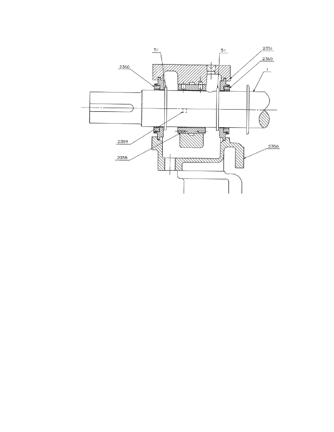
Figure L-9. Bearing Housings with Inpro/Seals
L.8
Bearing Housing Removal and Replacement
SST bearing housings are attached to the lower turbine casing with bolts. Two
dowel pins on each housing, maintain their position. Alignment of bearing
housings to the casing and to each other is essential for vibration-free operation and
long bearing life. Bearing housings are accurately aligned at the factory prior to
pinning. Should it be necessary to remove or replace a bearing housing, it is
essential that the alignment be checked and corrected, if necessary, prior to re-
installation of the rotor.
Bearing housing alignment is a precision process that requires skill, experience,
and precise measurement. If there is any question regarding the ability of site
personnel to properly align bearing housings, Dresser-Rand recommends that a
factory-trained serviceman be engaged to perform the service. Contact your
Dresser-Rand manufacturer’s representative or the Dresser-Rand factory to
schedule a service visit.
L.9
Turbine Rotor & Turbine Wheel Removal and Replacement
Refer to the following figures:
215
M-0
SST Turbine, General View
M-1
Trip Throttle Valve Assembly
M-2
Governor, Mounting Housing, and Trip Components
M-3
Gland Sealing Elements
M-4
Hi-Cap Bearing Case Assembly, Exhaust End
M-5
Bearing Housing Assembly, Exhaust End
M-6
Bearing Housing Assembly, Steam End
M-7
Bearing Housing Assembly, Steam End
M-8
Case, Rotor and Mechanical Gland Seals
M-9
Case, Rotor and Carbon Ring Gland Seals
L.9.1
Turbine Rotor Removal & Replacement
The governor, turbine cover, casing labyrinth seals (if so equipped), and carbon
rings must be removed or disassembled to remove the rotor.
Turbine Rotor Removal
a. For turbines where the governor is coupled to the shaft, remove the steam end
bearing case cap; then uncouple and remove the governor.
(See longitudinal
section, Appendix A). For a gear driven Woodward governor, disconnect the
governor linkage without disturbing the length of connecting rod, remove bolts
that fasten the governor to the housing and lift off the governor.
b. Remove the over-speed trip collar according to the procedure specified in
Section L.14.
c. Remove upper halves of bearing housings according to the procedure specified
in Section L.6.1.
d. Remove the top half of the turbine case according to the procedure specified in
Section L.3.
e. Remove shaft packing according to Section L.5.
f.
Remove cap from the exhaust end bearing case and steam end bearing case (if
not already removed in step 1.
g. Remove both main bearing top halves.
216
h. Arrange a suitable support for the rotor assembly. Verify that turbine wheel
blades and bearing journal surfaces on the shaft will not make contact with any
surrounding object. Verify that the assembly will not roll off the support.
i.
Use slings and a crane or hoist to lift the rotor assembly just out of the lower
half of bearings; then remove lower half of bearings. Use extreme care when
lifting the assembly to avoid damaging the wheel, blades, shaft, or sector.
j.
Place rotor assembly on the support.
Turbine Rotor Replacement
a.
Verify that the interior of the turbine casing is clean and that all foreign objects
have been removed.
b.
Clean or replace journal bearings (if so equipped) and lubricate journal area of
the shaft to prevent scratching or scoring.
c.
If so equipped, place lower journal half into the bearing housing. Position oil
rings so that they fit into openings provided in the bearing housings.
d.
Using slings and a crane or hoist, lower the rotor assembly into the casing. Use
care to avoid damage to the wheel, blades, shaft, or sector.
e.
Check clearance between first wheel and nozzle ring. This clearance is
obtained by properly locating the thrust bearing. See figure L-8 and thrust
bearing adjustment procedure in section L.6.2.
f.
Replace casing labyrinth seals (if so equipped) according to the procedure
specified in Section L.5.
g.
Replace turbine cover and gland housing upper halves
(if so equipped)
according to the procedure specified in Section L.3.1.
h.
Replace the sleeve bearing upper halves (if so equipped) and bearing housing
upper halves according to the procedure specified in Section L.6.
i.
Replace the governor mounting housing
j.
Replace over-speed bolt trip collar according to the procedure specified in
Section L.14.
k.
Replace governor drive coupling governor and associated linkage according to
the procedure specified in Section L.12.
L.9.2
Turbine Wheel Removal and Replacement
217
This operation is to be referred to Dresser-Rand service facilities.
CAUTION
DO NOT allow the heating FLAME TO IMPINGE on turbine
BLADES, as this could anneal and WEAKEN them.
WARNING
Exercise appropriate CAUTION in handling the HOT WHEEL
during disassembly and assembly.
CAUTION
Be certain to assemble the wheel and shaft with THE
SHORTER BLADES TOWARD the NON-DRIVE END OF THE
SHAFT. Otherwise, the rotor cannot be installed.
L.9.3
Turbine Rotor Balancing
Whenever a wheel or shaft is replaced, the wheel and shaft subassembly should be
dynamically balanced. This procedure must be performed by a Dresser-Rand
repair facility.
L.10
Nozzle Ring Removal and Replacement
Nozzle rings contain one or more nozzles which expand the inlet steam to a lower
pressure, creating the necessary kinetic energy (velocity) at the entrance of the first
wheel blading.
L.10.1 Nozzle Ring Removal
218
After the rotor and guide ring have been removed from the lower half turbine
casing—
a. Loosen and remove nozzle ring cap screws. This may, at times present
a problem. Broken screws will have to be extracted or drilled out.
Note: When nozzle ring is secured with inner and outer bolts, no caulking
strip is used.
b. The nozzle ring may now be lifted out of the casing. Mark the ring to
identify its location if reused (upper or lower half).
L.10.2 Nozzle Ring Replacement
Nozzle rings are caulked in at the outer periphery and bolted to the steam ring
nozzle bolting face of the main casing when a single row of bolting is used. When
a double row of bolting is used, there is not a caulking strip.
a. Identify the upper and lower half nozzle ring. If necessary check that the
valve port bridge walls match their seal surfaces using bluing or white lead.
b. Check that the clearance holes in the nozzle ring and tapped holes in the
steam ring face agree.
c. Thoroughly clean the sealing surface at the steam ring face. If the
surface is smooth, the most common sealing compounds are Turbo R or
Turbo 50. If the surface is rough, use Copaltite. If these compounds are
not available, use a key paste or a mixture of graphite and oil. If none of
these compounds is available, call Dresser-Rand Technical Support.
d. Bolt the nozzle ring half in place. The cap screws should be pulled tight
but not over-tightened. If Allen wrenches bend during tightening, the
screws are overstressed and their heads may snap off when the unit comes
up to temperature. Over-tightening of screws must be avoided. Prick-
punch head clearance holes at four positions so that cap screw heads (if
broken off) cannot come out into the steam path.
L.11
Hand-valve Removal and Replacement
Hand-valves are optional items. Depending on steam conditions, required power
and speed, and initial customer requirements, the turbine may incorporate no hand-
valves, one hand-valve, or two hand-valves.
219
The purpose of hand-valves is to isolate a nozzle or group of nozzles from inlet
steam, thereby allowing the turbine to operate at reduced power output without
excessive throttling. When operated at reduced power in this fashion, the turbine is
more efficient than it would be if all nozzles were active.
Hand-valves should be either fully open or fully closed, never in between.
Operating with a partially closed hand-valve is not only inefficient, but could result
in steam cutting of the seat resulting in excessive leakage. When putting the unit
into operation, do not close a hand-valve tightly until the turbine is up to operating
temperature and all parts are evenly heated. The reason for this is that the material
of the valve stem is subject to greater thermal expansion than the turbine casing,
and if the valve is closed tightly when cold, it may lock the valve in the closed
position making it difficult to open.
Refer to Figure L-10, Hand-valve Assembly.
L.11.1
Hand-valve Removal
WARNING
Close and tag inlet and exhaust isolating valves and open
drains to depressurize the turbine casing and steam chest
before maintaining hand-valves.
Note: Removal of the hand-valve is done from inside the turbine case.
a. Remove the turbine casing cover and bearing case covers, uncouple the turbine
rotor, and remove the carbon rings. See instructions in other sections of this
manual for these steps.
b. Remove the turbine rotor. Remove the nozzle ring.
c. Once the nozzle ring is removed you can see the hand-valve seat (761). Pull out
the hand-valve seat. The fit is on-line to 0.004” loose.
d. Remove the hand wheel (758). Remove the hand-valve bonnet (750).
e. Push the stem and disc assembly out towards the inside of the turbine. Remove
the old hand-valve packing (754). Note: Count the rings removed.
f. Clean the seat area, nozzle ring face, and all areas that might have sealant.
L.11.2
Hand-valve Replacement
a. Inspect the stem and disc assembly. Hand-valve collar (752) should be tight
and staked to the disc (751).
b. Insert the new stem and disc assembly into the turbine hand-valve location.
220
c. Make sure the seat (761) and the bore of the turbine case are clean. Insert the
seat into the hole where it was removed. If there is a slight interference, cool
down the seat in a freezer or with liquid Nitrogen.
d. Install the nozzle ring in accordance with instructions in other sections of this
manual.
e. Assemble new packing (754). Put in the same number of packing rings as
were removed.
f.
Assemble bonnet (750) and hand wheel (758). Tighten the bonnet to compress
the packing until you feel a slight drag on the stem when you screw it in and
out.
L.11.3
Reassembly of the Turbine Rotor and Upper Half Casing
a. Clean all surface areas (turbine casing split-line, bearing case split-lines, etc).
b. Assemble the carbon rings, turbine cover, and bearing case covers per
instructions given in other sections of this manual.
L11.4
Handvalve Adjustment
a. One steam is admitted into the unit, re-tighten the hand-valve bonnet so there
is no steam leaking out of the steam area. This might have to be done again
when there is full pressure inside the casing to prevent leakage at the high
internal pressure.
b. The valve stem should be screwed fully closed or fully open. It should never
be partially open or closed.
221
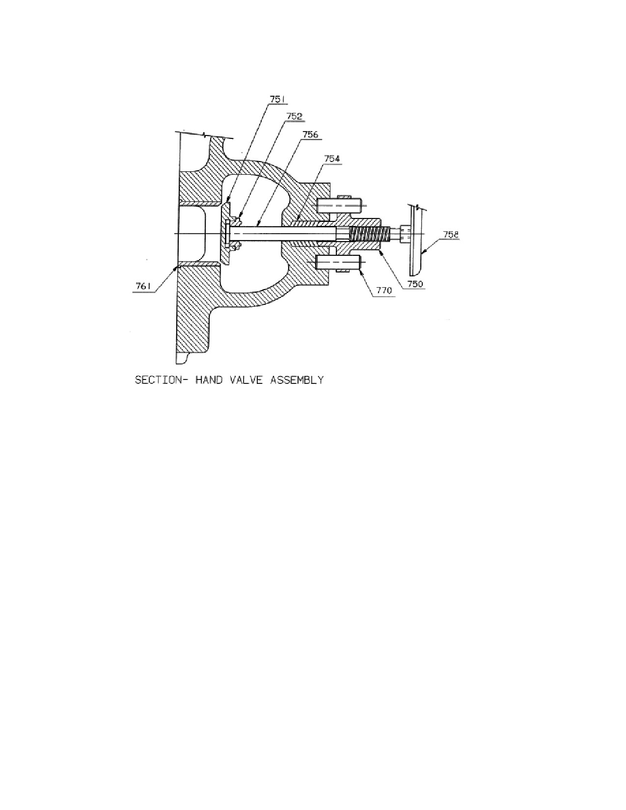
Figure L-10. Hand Valve Assembly
L.12
Governor Removal and Replacement
Refer to the following figures:
M-2
Governor, Mounting Housing, and Bolt Trip Components
L-11
Direct Drive Governor Assembly
L-12
Gear Drive Governor Assembly
L.12.1
General
Field service on the oil relay governor is normally limited to yearly oil changes per
Section J, and droop setting adjustment, which is described in the governor manual
provided in Appendix B.
222
In the event that the governor exhibits operational problems, Dresser-Rand
recommends that the governor be removed as a unit and returned to the factory for
repair or overhaul, as required. In the meantime, a replacement oil relay governor
can be quickly and easily installed to keep the turbine in operation. The Dresser-
Rand factory maintains a stock of certain TG replacement governors for rapid field
delivery, and is equipped to perform comprehensive repair, overhaul, and testing of
oil relay governors.
For shipment, care should be exercised to support the governor by its mounting
flange and not by its shaft extension.
Some governors are direct-drive types coupled to the end of the turbine shaft by
couplings, as shown in Figure L-11. Others, due to speed requirements, are
connected by right-angle gear reduction units, as shown in Figure L-12.
L.12.2
Governor Removal (Direct Drive)
a. Drain oil from governor (300) at drain.
b. Disconnect connecting rod
(1075) at governor lever
(445) by removing
connecting rod end (1070). Do not disturb position of rod end (1070) bearing
on rod (to preserve open/close stroke adjustment).
c. Rotate turbine shaft (1), if necessary, to disengage coupling hub (303) by
loosening coupling setscrew.
d. Prop or support governor (300); then, unbolt governor from mounting housing
(201) and slide governor out of mounting housing. Be careful not to lose the
governor key.
e. Remove governor trip latch (446) (if same governor is not to be used as
temporary replacement) by loosening its setscrew.
223
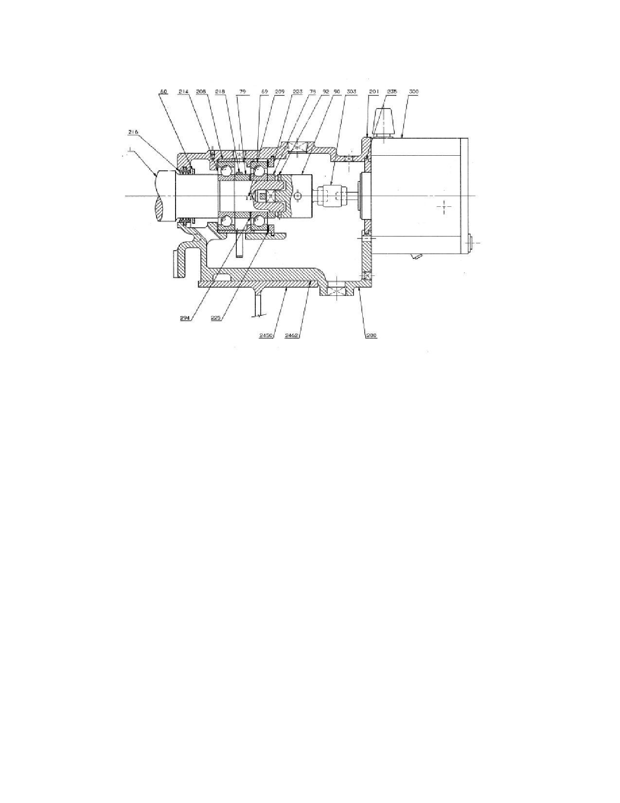
Figure L-11. Direct Drive Governor Assembly
L.12.3
Governor Replacement (Direct Drive)
a. Install governor trip latch (446) and tighten lever set-screw securely.
b. Slip coupling spider between jaws of coupling (303) hub on turbine shaft
extension.
c. Install coupling hub (303) on governor shaft.
d. Slide governor (300) into place on mounting housing (201), verifying that
coupling (303) engages properly.
e. Install and tighten screws to secure governor to mounting housing (303). There
should be 1/16 inch (1.6 mm) play for the coupling spider between coupling
hubs. Coupling access is available through the open side of the mounting
housing. Tighten screw to secure coupling.
f.
Reconnect connecting rod (1075).
g. Remove governor breather cap and fill governor with oil to proper level
indicated on sight glass.
224
h. Rotate turbine shaft (1) slowly by hand to ensure that governor and coupling
are free to turn when placed in operation.
L.12.4
Governor Removal (Gear Drive)
a. Drain oil from governor (300).
b. Disconnect connecting rod
(1075) at governor lever
(445) by removing
connecting rod bolt. Do not disturb position of rod end bearing on rod (to
preserve open/close stroke adjustment).
c. Remove cap screws securing governor (300) to gearbox (316) adapter; then,
lift governor vertically from adapter. The coupling (303) will remain on the
governor shaft at removal. Do not remove governor lever or coupling from
governor if same governor is to be installed again. If a new governor is to be
installed, transfer lever and coupling (with keys) to new governor. The lever
and coupling are secured to governor shafts by setscrews.
Note: The coupling, which joins the governor and gearbox shafts, is supplied with
the gearbox.
L.12.5
Governor Replacement (Gear Drive)
a. Verify that coupling and keys are installed on governor shaft, and that the
governor lever is mounted to its shaft at the side of the governor.
b. Lower governor (300) on gearbox (316) adapter with coupling key slots
positioned to allow mating of keys and key slots of shaft and coupling (303) as
governor and adapter flanges meet.
c. Rotate governor to align cap screw holes; then, install cap screws tightly.
L.12.6
Governor Drive Gearbox Removal
The governor (300) must be removed according to the procedure specified in
Section L.12.4, above, before the gear (310) and governor drive shaft (306) can be
removed.
a. Drain oil from steam end bearing case (200).
b. Remove pin (304) from coupling (303) to release coupling from governor
drive shaft (306).
225
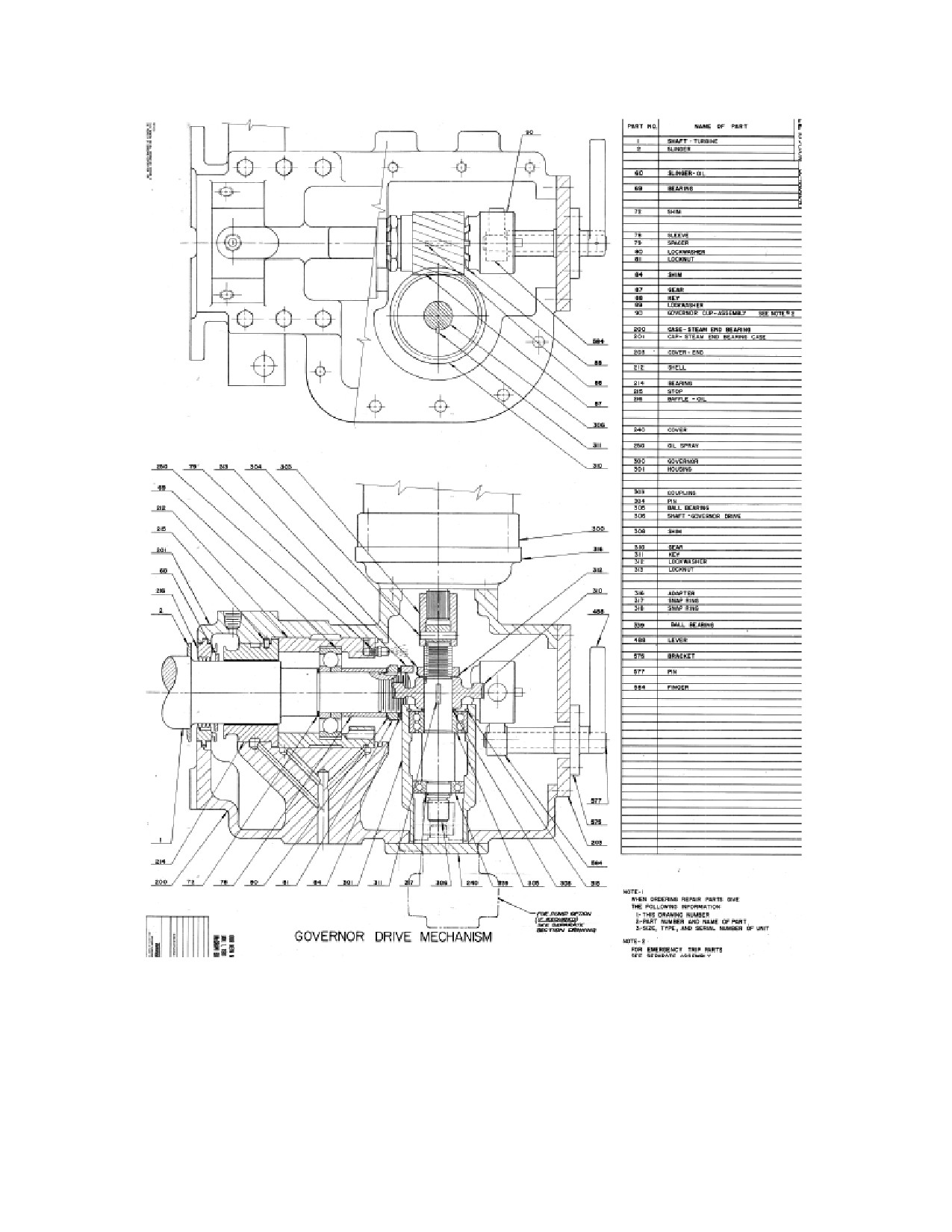
Figure L-12. Gear Drive Governor Assembly
226
c. Remove lock-nut (313) and lock washer (312) retaining gear onto governor
drive shaft (306). Slide gear (310) up off of shaft (306), being careful not to
lose key (311).
d. Remove shim (308) being careful to document order of removal/replacement.
e. Remove snap ring (318) retaining bearing into housing (301). At this point the
governor drive shaft (306) can be extracted from the housing (301).
f. Prop or support governor drive shaft (306) in a vice being careful not to scar the
shaft surface and remove the snap ring (318) retaining the ball bearing (339).
At this point both ball bearings (339) and (305) can be pressed from the
governor drive shaft (306) for replacement.
The Dresser-Rand factory maintains a stock of replacement governor drive shaft
parts for rapid delivery to the user, and is equipped to perform complete repair and
overhaul service on gearboxes.
L.12.7
Governor Drive Gearbox Replacement
a. Install governor drive shaft (306) into housing (301) and install snap ring
(318). Replace shim (308), locate key (311) into slot on governor drive shaft
(306) and install gear (310), lock washer (312) and lock-nut (313) securing
gear onto governor drive shaft (306).
b. Install coupling (303) and pin (304) into and onto governor drive shaft (306).
c. Before installing the governor, check and record the backlash of the new gear.
In future inspections, use this dimension as a guide in determining the
necessity for replacement. If backlash is questionable use Dyken layout blue
or printers ink to check for proper mesh of gears. When a good mesh is
indicated, the gear may remain in service.
c. Mount governor (3004) onto housing (316), verifying that the splines on the
governor shaft slide into the coupling (303) easily. Install mounting bolts to
secure governor (300) onto housing (316).
d. Fill hydraulic governor with oil. Refer to Woodward Bulletin
25071 in
Appendix B.
e. Fill steam end bearing case (200) with recommended lubricant to required
level, as indicated by oil sight gage plug.
L.12.8
Governor Valve Travel and Linkage Adjustment
227
Refer to the following figures:
M-1
Trip Throttle Valve Assembly
M-2
Governor, Mounting Housing, and Trip Components
L-11
Direct Drive Governor Assembly
L-12
Gear Drive Governor Assembly
L-13
Trip Valve Linkage
Adjustment of the linkage between the governor and throttle should be carried out
whenever linkage components, or the governor itself, are replaced. Rig the throttle
linkage as follows:
a. Check that the governor linkage is approximately at right angles to governor
connecting rod.
(See upper view of figure L-13). Adjust the length of the
connection rod as necessary.
b. Back off the lock nuts on both sides of the governor lever block.
c. Pull the connecting rod out of the Woodward governor as far as it will go.
d. Push the connecting rod back toward the governor 3/16”/4.76mm. (To hold
this position while making the adjustment, place a block equal to the existing
clearance between the connecting rod end and the mating fitting on the
governor—see lower view in Figure L-18.
e. Push the valve stem in until the valve just seats.
f. Tighten the lock nuts on both sides of the governor lever block to secure
the ajdustment.
L.13
Trip and Throttle Valve Maintenance
CAUTION
228
If the turbine is equipped with a throttle or trip valve
manufactured by a party other than Dresser-Rand refer to the
accessory documentation section of this manual for installation,
operation, and repair and maintenance instructions.
Refer to the following figures:
M-1
Trip and Throttle Valve Assembly
M-2
Governor, Mounting Housing, and Trip Components
L-13
Trip Valve Trip Linkage
L-14
Throttle Valve Trip Linkage
The design of the Dresser-Rand trip and throttle valve assembly permits routine
maintenance (disassembly and assembly) procedures while still mounted on the
turbine and without disconnecting the inlet piping. For major overhaul or
necessary machine work, remove the valve as indicated below.
WARNING
BEFORE SERVICING ANY COMPONENT of the combo valve,
verify that the ISOLATING VALVE in the INLET LINE is
CLOSED AND TAGGED. If the turbine is connected to the
exhaust steam header, CLOSE the ISOLATING VALVE in the
EXHAUST LINE AND TAG IT. OPEN ALL TURBINE DRAINS
to ensure venting of all pressure before disassembly begins.
CAUTION
In the following procedures, remove and replace all parts slowly
and carefully to avoid damage (digs, bends, scoring, chipping,
etc.) to conditioned surfaces. DO NOT use excessive force to
remove parts. Use backup bracing for unsupported parts when
taper pins or dowels are removed by hammer and drifts.
L.13.1
Valve Removal from Turbine
The steam strainer should be removed and cleaned at least once a year and
replaced every three years. Since it is necessary to remove the governor
valve before the strainer can be withdrawn, the governor valve and its seats
should be inspected and reground if necessary. To replace either the
229
governor valve or the steam strainer, proceed as follows:
(See Figure L-
14).
a.
Remove valve adjusting nut and washer.
Note: Do not disturb settings of lock nuts and connecting rod-ends (17 and 19) on
rod (18) unless parts need to be replaced. These are factory-set to provide
the required stroke for the rod.
b. Remove snap ring from the governor lever pin; then remove the pin and
carefully slide the governor lever off the governor valve stem.
c. Remove the nuts that secure the steam chest cover to the steam chest and
carefully remove the cover without contacting the valve stem.
d. Pull out the governor valve (see governor section, Appendix A).
e. Remove bolting at turbine flange; then, lift valve by slings and hoist to service
area for further disassembly.
f.
Remove as an assembly together with the steam strainer.
g. Perform necessary maintenance and reassemble by reversing the removal
procedure.
h. After completing installation, set the following:
Overspeed Trip
Overspeed Trip Linkage
Governor Valve Travel
230
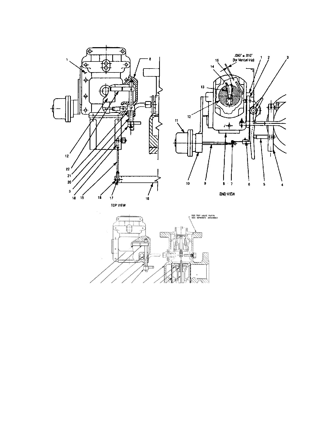
Finger 22
21
20
3 Valve Seat Bushing
Stem
Strainer
Figure L-13. Overspeed and Governor Valve Linkage
Legend
15. Lockscrew
1. Cap
8. Case - Steam End
16. Lever - Governor
2. Lever
9. Steam - Bellows
17. Pin
3. Lever - Trip
10. Bracket - Low Oil Trip
18. Rod End
4. Lever - Trip Connection
11. Low Oil Trip
19. Rod - Connecting
5. Rod - Trip Connection
12. Governor Cup
20. Shaft - Trip
6. Plate - Top
13. Adjusting Screw
21. Collar
7. Latch - Trip Assembly
14. Emergency Weight
22. Trip Finger & Lever
231
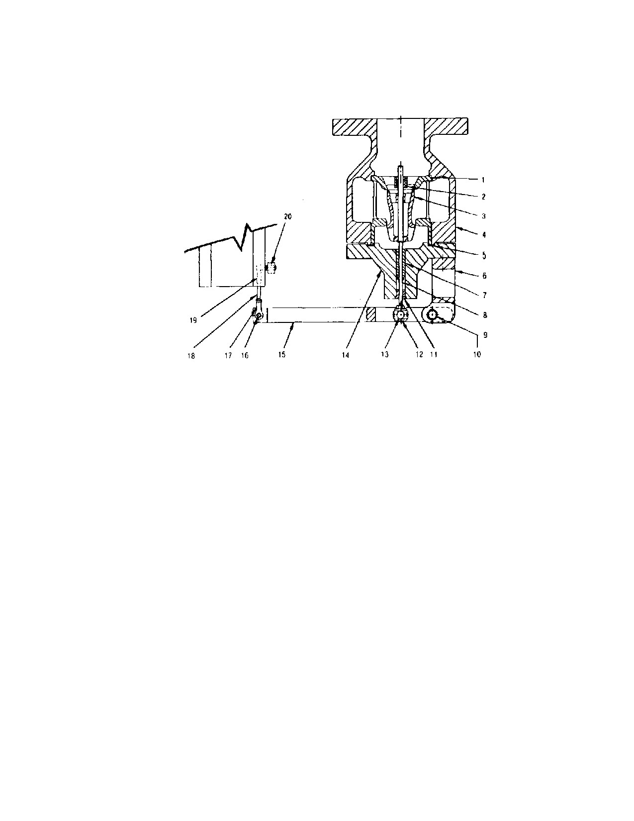
Figure L-14. Throttle Valve Linkage
Legend
1. Bushing - Valve Seat
8. Stem - Valve
14. Cover - Steam Chest
2. Bushing — Valve Stem
9. Pin
15. Lever - Governor
3. Valve
10. Bearing
16. Pin
4. Steam Chest
11. Bushing - Valve
17. Rod End
5. Gasket
Stem-Outer
18. Rod- Connecting
6. Bracket - Governor Lever
12. Block - Pivot
19. Rod End
7. Bushing - Valve Stem - Inner13. Block - Sliding
20. Lever
L.13.2
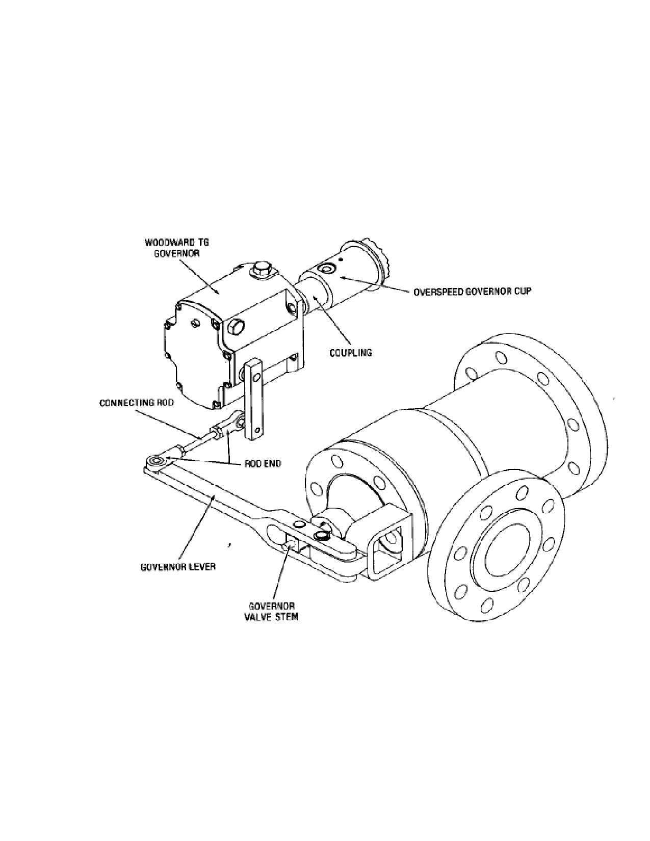
Woodward TG Governor Valve Travel Setting
a. Remove pin that connects the governor lever to the connecting rod end.
(See Figure L-15.)
b. Push the governor lever in until valve just seats and hold this position.
c. Push connecting rod toward the valve closing direction (see arrow on
illustration) as far as it will go and hold this position.
d. Adjust the length of the connecting rod so that the hole for the pin in the
rod end is approximately 1/8”/3.75mm beyond the mating hole in the
governor rod.
e. Release the connecting rod and insert the connecting pin.
L.13.3
Woodward TG-13L Governor with Fisher Control
232
The Fisher pneumatic speed mechanism acts in conjunction with the Woodward
TG-13L governor to adjust the turbine speed to refined limits. If speed re-
adjustment is desired, re-locate the pin to another hole in the lever (see Governor
Speed Control Schematic, Appendix A).
The Fisher control can be used as a direct or reverse type control; either to increase governor
speed settings as control air pressure signal increases, or the reverse type to increase governor
speed as control air pressure signal
decreases.
Figure L-15. Governor Valve Travel Setting - Woodward TG Governor
233
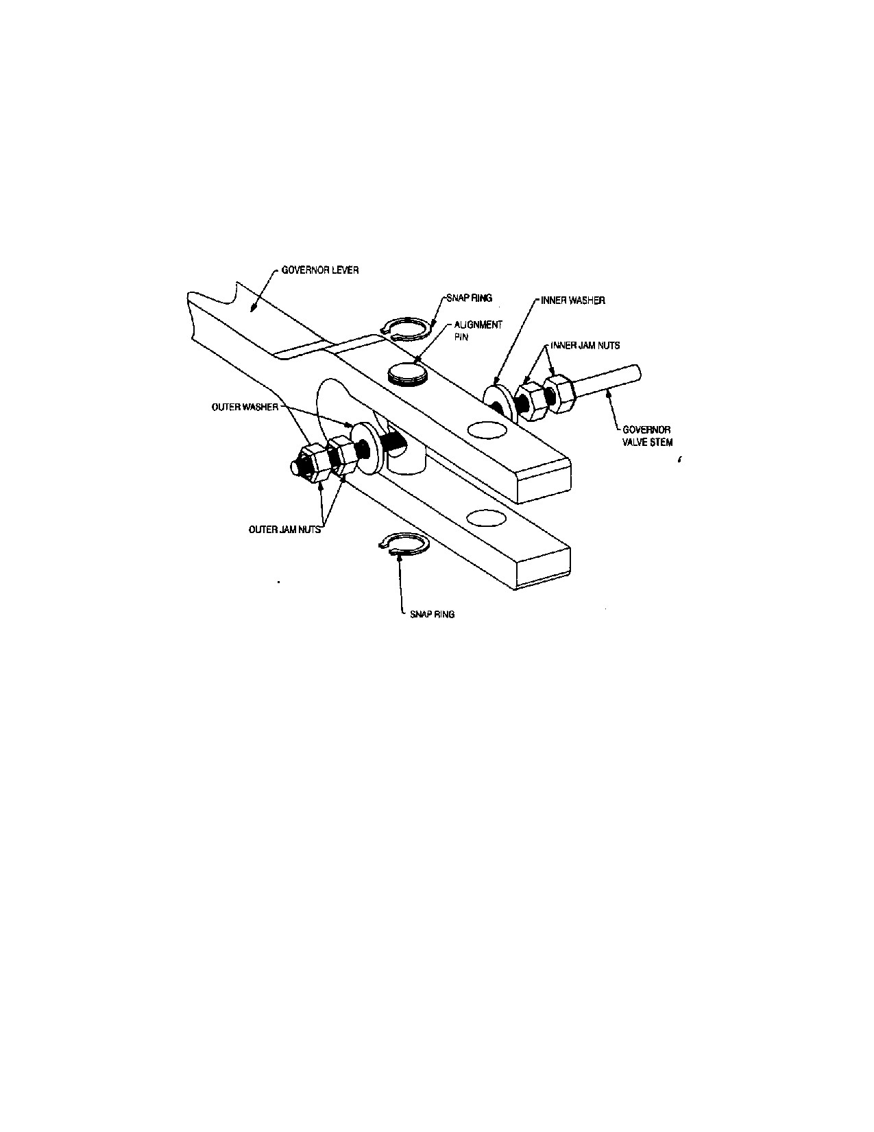
L.13.4
Alternate Governor Valve Stem Connection
Some Dresser-Rand turbines may be equipped with an alternate method of securing
the governor valve stem to the rotating governor lever. This connection should be
installed so that the inner and outer washers are tight against the alignment pin.
The operator should be able to turn the washers by hand with no lost motion after
tightening the inner and outer jam nuts.
Figure L-16 Alternate Governor Valve Stem Connection
234
L.14
Emergency Valve Maintenance
WARNING
BEFORE SERVICING ANY COMPONENT of the Overspeed
Trip Mechanism, verify that the ISOLATING VALVE in the
INLET LINE is CLOSED AND TAGGED. If the turbine is
connected to the exhaust steam header, CLOSE the
ISOLATING VALVE in the EXHAUST LINE AND TAG IT.
OPEN ALL TURBINE DRAINS to ensure venting of all pressure
before disassembly begins.
The overspeed trip mechanism may be readily disassembled or assembled at a
workbench and then mounted to the turbine as a subassembly. Prerequisites for this
process are removal of the governor and coupling according to the procedure
specified in Section L.12, followed by removal of the overspeed trip collar (90)
from shaft (1), as described below.
It is important that the entire emergency trip system be properly adjusted and free
of binding or lost motion. The operation of the overspeed trip should be tested as
often as possible, especially at times that maintenance is performed and a
permanent record should be kept of these tests. The over-speed trip should
function to shut down the turbine within 2% of the speed specified on the turbine
data sheets. If the operational tests in Section I.6 indicate a requirement for
adjustment, proceed as follows:
L.14.1
Governor Cup Removal
Refer to the following figures:
L-13
Overspeed and Governor Valve Linkage
L-14
Throttle Valve Linkage
L-15
Governor Cup Assembly
a. Gain access to the overspeed governor cup.
For turbines with a Woodward gear driven governor - remove bearing
case end cover.
For turbines with a Woodward governor that is coupled to the shaft -
remove the steam end bearing case cap.
235
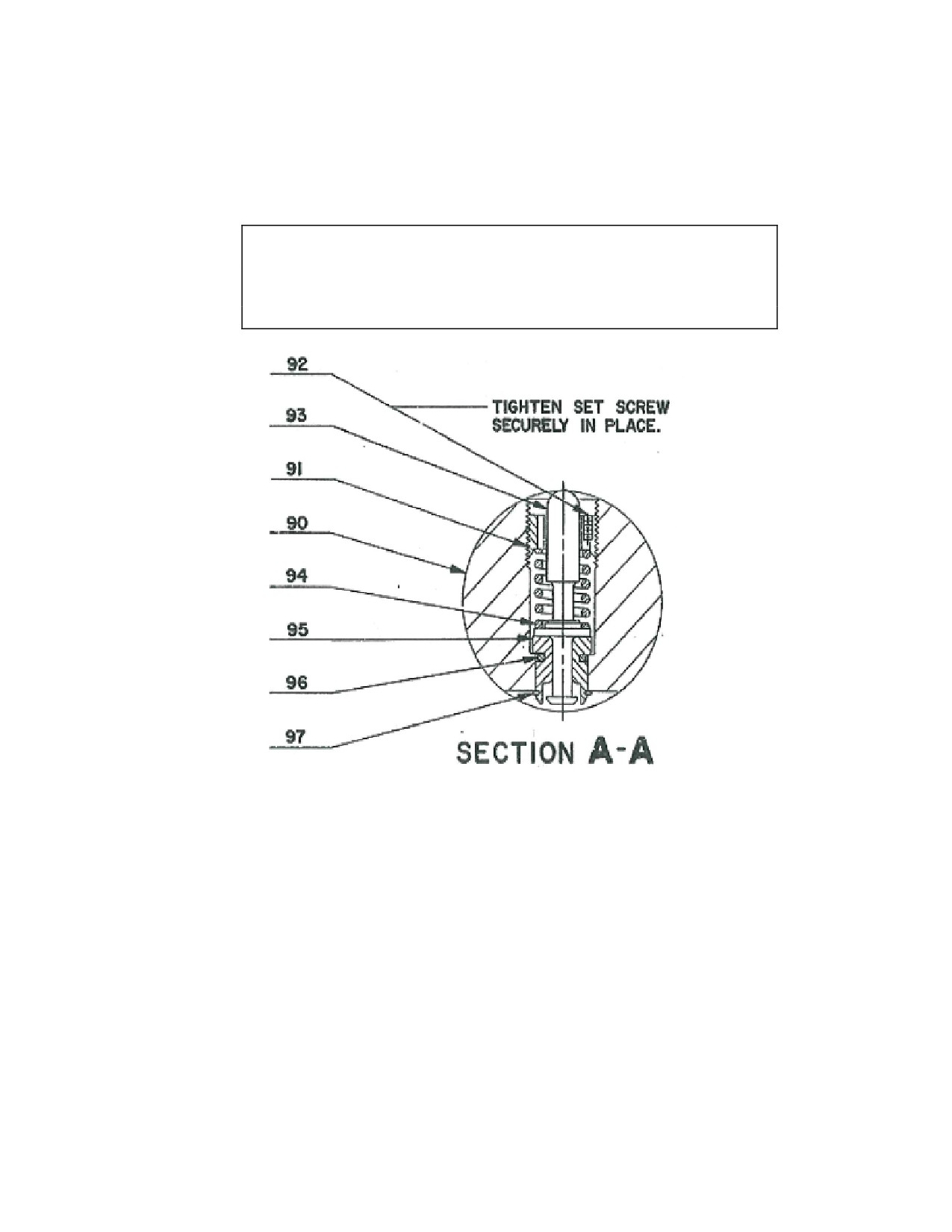
b. Manually rotate the turbine shaft (1) until the lock screw (P/N 15, Figure L-13
or P/N 92, Figure L-15) is accessible; then loosen the lock screw.
CAUTION
If the Overspeed Governor Cup Assembly is replaced, the rotor
may need to be re-balanced with the new assembly attached.
Figure L-17. Governor Cup Assembly
Legend:
90. Cup - Governor
94. Spring
91. Screw - Adjusting
95. Bushing - Weight
92. Set Screw
96. Ring - Retaining-Open type
93. Weight
97. Ring - Retaining-External type
b. Using a suitable spanner tool, turn the adjusting screw (91) clockwise to raise
the tripping speed or counterclockwise to lower, as necessary.
c. Tighten the lock screw (15 or 92) (setscrew) securely to lock the adjustment
position, then repeat the over-speed trip test (see warning below).
236
WARNING
The overspeed trip assembly should be locked in place before
starting the turbine. Four checks to make are as follows:
1. The overspeed governor cup must be tightly screwed into
the shaft.
2. If supplied, one of the tabs of the lock-washer is bent into
the miller slot of the overspeed cup.
(The overspeed cup will
have two milled slots for the tabs of the lock-washer, but it will
only be possible to line up one of the tabs. This is due to the
fact that the tabs are not symmetrically located around the
outer diameter. There is no need for concern as long as one of
the tabs can be completely bent over into the slot.)
3. If the overspeed cup has drilled and tapped holes for half
dog point set screws, the shaft must be drilled at final assembly
with the overspeed cup in accordance with the table below to
ensure the tip of the dog point locks into the shaft. The set
screws must be tightened and staked into place.
4. The run-out of the cup must also be checked and adjusted
to within 0.002 inch (.05 mm) total indicated run-out.
L.14.2
Governor Cup Replacement
237
CAUTION
The adjusting screw/spring combination has been pre-set at the
factory for the trip speed originally set when the turbine was
shipped. Refer to Section L.14.7, Trip Linkage Adjustment, if
minor trip speed changes are to be made.
WARNING
Adjusting Screw (91), spring (94), and setscrew (92) are a
FACTORY-CONFIGURED SET, selected to obtain the proper
trip speed for a specific turbine. DO NOT MIX OR
INTERCHANGE THESE PARTS with similar parts from other
turbines or attempt to modify these components. Consult your
local Dresser-Rand manufacturer’s representative or the factory
if replacement parts are needed.
L.14.3
Trip Mechanism Disassembly
For 4” and 6” trip and throttle valve systems, the clearance between the overspeed trip
lever (Figure L-13) and the emergency weight (P/N 14) or (P/N 93 in Figure L-14) is
properly set at the factory for 0.060”/1.524mm plus or minus 0.010”/0.254mm. Gain
access to the over-speed governor cup as described in the preceding section L.14.1.
For 4” and 6” Venturi trip systems, the clearance between the over-speed trip lever
(figure L-13) and the emergency weight (P/N 14 or P/N 93) is properly set at the factory
for (0.090”/2.286mm plus or minus 0.010”/0.254mm. Gain access to the overspeed
governor cup as described in section L.14.1.
Rotate the turbine shaft (1) to position the overspeed weight adjacent to the overspeed
trip lever and measure the clearance. If adjustment is necessary, proceed as follows:
a. Loosen lock screw that secures the valve lever trip connection to the valve
spindle.
b. Slide valve lever connection along the valve spindle away from the steam
chest to increase the clearance, toward the steam chest to decrease the
clearance.
c. Tighten the lock screw to securely hold the valve lever connection.
238
L.14.4
Emergency Valve Travel
a. Unlatch valve lever (P/N 3, Figure L-13) to close emergency valve.
b. Manually pull out on the governor linkage to close the governor valve. On the
turbine, it may be necessary to remove the pin from the connecting rod. (See
lower view of Figure L-18)
c. With the governor valve fully closed, raise the valve lever until the emergency
valve will not open further (do not spring the valve lever).
d. Measure the clearance between the latch surface of the valve lever and the
latch surface of the trip lever. The clearance should be approximately ¼”/6.35
mm.
e. If adjustment is required, loosen the lock screw in the valve lever connection;
then reposition the valve lever connection and serrated valve spindle clockwise
or counter-clockwise as necessary to obtain the correct clearance.
NOTE: After making this adjustment, it will be necessary to re-check the
setting of the over-speed trip linkage.
L.14.5
Emergency Valve Removal and Replacement
a. Remove governor valve and steam strainer as described in section L.13.1.
b. Remove lock screw in the valve lever connection; then slide the valve lever
connection off the serrated valve spindle.
c. Remove access plug in the steam chest located above the valve spindle; then
remove the lock screw that secures the valve spindle to the valve link.
d. Remove access plug in the steam chest in line with the valve spindle and
withdraw the valve spindle.
e. Remove the valve link by sliding up and away from the valve stem.
d. Remove the valve portion of the assembly and inspect the valve seat.
NOTE: If the valve seat must be replaced, the steam chest must be removed from
the turbine.
e. Re-assemble and install the emergency valve by reversing the removal
procedure.
239
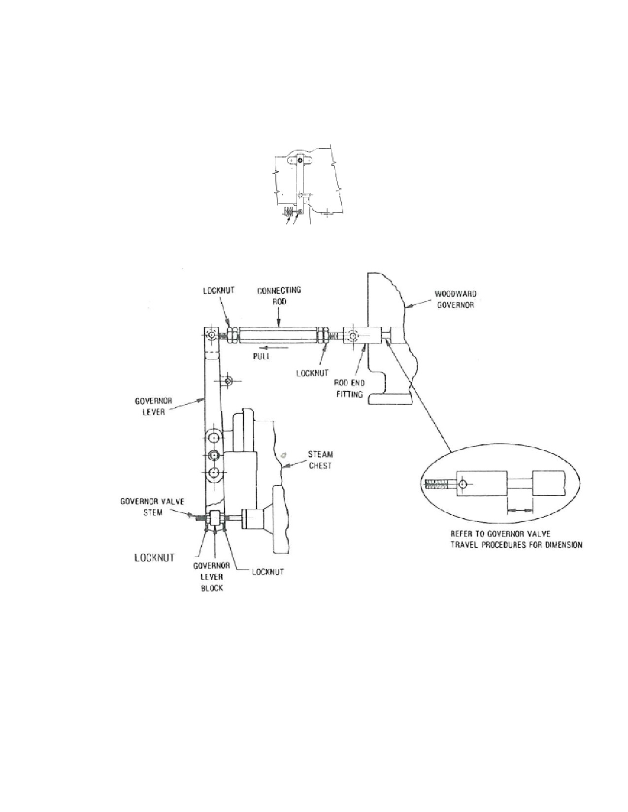
4
5
Figure L-18. Trip Valve Lever Orientation-Trip Valve Open and Closed
After completing installation, set the following:
240
Overspeed trip
Overspeed trip linkage
Governor valve travel
Emergency valve travel
L.14.6
Trip and Throttle Valve and Steam Strainer
The following are procedures for replacement of the steam strainer:
a. Close the main steam valve.
a. Disconnect the pressure and drain line connections at the oil cylinder flanges.
c. Disconnect the linkage from the governor lever.
d. Remove the bolts that fasten the trip throttle valve body to the valve body
cover.
e. Remove the bolts that fasten the valve body cover to the valve body; then lift
off the valve body cover.
f.
Lift out the emergency valve guide.
g. Pull out the steam strainer.
h. Perform the necessary maintenance and re-assemble by reversing the removal
procedure.
i.
For procedures on a vendor valve, see Appendix B.
NOTE: The 6” trip and throttle valve cover is equipped with a throttle screw that
regulates the amount of steam from the inlet side of the valve to the chamber
above the main disc. If chattering of the main disc is encountered when
opening the valve, it is necessary to increase the leakage to the chamber by
turning the throttle screw counter-clockwise. If, however, the hand-wheel
effort appears excessive, it can be reduced by turning the throttle screw
clockwise, thus decreasing the leakage to the chamber. A pipe tap is provided
in the cover to be used for a pressure gauge to check the pressure chamber
after the pilot valve has been opened. This leakage pressure should be
approximately 25% of the line operating pressure.
241
Section M
Replacement Parts/Factory Service
M.1
Factory Replacement Parts
Dresser-Rand Turbine recommends that only Dresser-Rand-supplied parts be used
in Dresser-Rand turbines. The use of Dresser-Rand parts ensures that replacement
components are manufactured from the highest quality materials, to exacting
tolerances and specifications, thereby assuring safe, efficient, long-lasting, and
maintenance-free operation under service conditions for which the turbine was
designed and built.
Dresser-Rand and selected Dresser-Rand manufacturer’s representatives maintain a
supply of the most frequently requested spare parts for immediate shipment
worldwide. Parts requested less frequently can be manufactured quickly on an
emergency basis when required.
Your Dresser-Rand manufacturer’s representative can supply you with a stocking
list of recommended spare parts for your turbine or turbines, allowing you to stock
spare parts at your facility. Refer to Section M.4, Recommended Spare Parts.
M.2
Turbine Identification
Dresser-Rand SST turbines are marked with a serial number, which appears on the
nameplate and is also, stamped on horizontal flange of the inlet casing. This serial
number is used by the factory to identify the turbine and should be used in all
inquiries and parts orders.
M.3
Parts Identification
When inquiring to determine parts availability, or when placing an order for spare
parts, the following minimum information is required:
Item
Typical Example
Turbine serial number:
XXXX
Part description:
Shaft
Reference number:
21
242
Section Drawing
LE-169235-N
If the turbine parts list is available, then the Dresser-Rand part number should also
be specified.
WARNING
Modification of, incorrect repair of, or use of non-DRESSER-
RAND repair parts on this turbine could result in serious
malfunction or explosion that could result in serious injury or
death. Such actions will also invalidate ATEX Directive &
Machinery Directive Certifications for turbines that are in
compliance with those European Directives. Refer to Section M
- Replacement Parts/Factory Service.
M.4
Recommended Spare Parts
The recommended spare parts for a turbine owner is provided in the service
manual. The inventory recommendation for spare parts is based on Dresser-Rand’s
long experience with turbine applications.
M.5
Ordering Parts
Contact your local Dresser-Rand manufacturer’s representative to order parts. Your
representative will be pleased to provide any assistance you may require, as well as
to quote prices and delivery dates.
The following information is required when placing a parts order:
1.
Your purchase order number.
2.
Complete billing, shipping, and marking instructions.
3.
Turbine serial number--from nameplate or horizontal flange of inlet casing.
4. Turbine frame size--from nameplate, i.e., 300, 500, 700, etc.
5. Quantity of each part or assembly.
6.
Part or assembly reference number from drawing, illustration, or text.
7. Section drawing the reference number was taken from.
8. Description of part or assembly.
243