Instruction Manual for Single Stage 350, 500, and 700 Frame Steam Turbines - page 3
(38°C) to qualify for ring oiled lubrication. Heat deflectors and air maze breathers
must be used when the maximum operating exhaust temperature exceeds 400°F
(204°C).
Cooling water for the bearing case is recommended for all ring-oiled turbines.
Approximately 2 GPM of fresh water at 90°F (82°C) or less is required for cooling
the lubricating oil for each bearing housing. Cooling water is recommended when
the temperature of the bearing case cap exceeds 150°F (82°C). Maximum allowable
water pressure is 75 PSIG (517 KPAG). See Figure 25 for a typical bearing case
water piping schematic for ring oiled turbines.
The cooling water connections to the oil cooler are shown on the outline drawing
or oil piping diagram in Appendix A. The turbine data sheets specify the required
volume. The water outlet piping should be arranged to discharge into an open sight
drain where the operator can observe it. A water leg of at least six inches in height
should be placed in the outlet line adjacent to the cooler to assure the cooler being
kept full of water.
CAUTION
DO NOT RUN turbines equipped with oil ring lubrication at
speeds LESS THAN 950 RPM. The OIL RINGS WILL NOT
OPERATE CORRECTLY at these speeds, causing BEARING
FAILURE due to lack of lubrication.
The presence of oil in the constant level oilers does not
necessarily mean that oil in the bearing housings is at the
proper level.
Note: There are certain speeds and temperatures where Dresser-Rand
allows operation without cooling water. (Synthetic oil is required.)
F.4
Mist Oil System Lubrication
WARNING
124
Lubrication System
If the turbine is supplied with mist oil lubrication, oil mist could
escape from the bearing housing vents or oiler. If there is the
possibility that these could be ignited by equipment or
processes in the proximity of the turbine they should be piped
to a safe area.
The turbine may be lubricated by a facility mist oil supply. When a turbine
utilizes a system of this type, a diagram that shows turbine connections and piping
is provided in Appendix A.
F.5
Circulating Oil Cooling System
The circulating system is the next step up from the ring oil system with water cooling. This
system must be used when oil temperature in the bearing housings could exceed 180°F (82°C)
and/or the exhaust temperature exceeds 550°F (82°C). This elevated temperature is
normally caused by an increase in shaft/bearing rubbing speeds and/or elevated inlet or
exhaust steam temperatures being transmitted from the wheel casing to the bearing cases.
The circulating system is basically a ring lubrication system. The difference is that a
shaft driven direct drive pump which circulates oil out of the bearing cases for
additional cooling has been added. At higher exhaust temperatures, an external oil
cooler is added to the system.
The pump supplied with this system is a positive displacement gear type pump. It is
mounted on the shaft at the exhaust end of the turbine. The upper half of the exhaust
end bearing case serves as a housing for the pump. The same pump is used regardless
of turbine rotation. The pump may be mounted off the turbine shaft at the steam
end when design allows.
A standpipe or overflow port is located at each bearing case to maintain the correct
oil level.
F.6
Pressure Lubrication System
Force-feed (pressure) lubrication systems, mandatory on SST turbines operating
above 5000 RPM or when normal exhaust temperature is 650F (343C) or higher,
employ a positive displacement pump to draw oil from a reservoir which is then
cooled, filtered and delivered under pressure to the turbine bearings. The used oil
drains from the turbine bearing housings by gravity and flows back to the reservoir
to be reused.
125
Force feed lubrication system reservoir/console assemblies must be located so that
the oil drain piping between the turbine bearing housings and the reservoir’s oil
return connection slopes a minimum of 0.5 inches per foot (40 mm per meter).
CAUTION
The oil drains must be free flowing at atmospheric pressure.
Under no circumstances should the oil drains be pressurized or
have a vacuum applied. Horizontal pipe runs should be sloped
continuously, at least 0.5 inches per foot [40 mm per meter],
towards the reservoir.
Refer to instructions from the lubrication system supplier.
CAUTION
All lubrication oil piping tubing, and system components, that
have not been pre-charged, should be flushed prior to
assembly. The assembled lubrication oil system should be
flushed prior to turbine initial start-up.
F.6.1
Design Parameters for Turbine Pressure Lubrication Oil Systems
SST turbines supplied with sleeve bearings and a standard ball thrust bearing
require:
Normal Oil Supply Temperature
= 120° F (49° C)
Normal Oil Supply Pressure
= 20 - 25 psig (137 - 172 kPag)
Oil Filtration
= 25 micron or better
126
Lubrication System
Bearing Cases
GPM
Heat Load
Steam End Exhaust End
Simple/Simple
2
1
300 BTU/Min
HiCap/Simple
4
1
500 BTU/Min
W/Ball Thrust
HiCap/Simple
11
1
1000 BTU/Min
W/Tilt Pad Thrust
Refer to Section F.12, Lubricating Oil Selection Guidelines, and to the certified
drawings in Appendix A for a description of the supplied hardware, the specific
lubricating oil requirements, the oil flow, and the heat load applicable to the
purchased equipment package.
CAUTION
SST turbines supplied with a tilting pad thrust bearing or
turbines sharing lubrication with a gear reducer or driven
equipment, will require additional oil flow and heat load
capacity and may require the use of special viscosity
lubricants. Refer to the certified drawings in Appendix A for a
description of the lubricating oil system requirements.
127

F.7
Cooling Water to Bearing Housing Water Jackets
Tables F-1, Cooling Water Requirement, specifies when cooling water to bearing
housing water jackets is required. This requirement is based on the type of
lubrication system supplied with the turbine, the steam conditions, and the ambient
conditions. Refer to the certified drawings in Appendix A for specific cooling
water requirements for your turbines.
Lubrication Type
Cooling Water to Bearing
Cooling Water to
Housing Mandatory
Bearing Housing
Optional
Standard oil ring
X
Cooling water supply
temperatures must not
exceed 100°F (43°C)
Standard oil ring
X
with circulating oil
Force feed
X
Table F-1. Cooling Water Requirement
Cooling water for the bearing case for ring oiled turbines is recommended for all
ring-oiled turbines. Approximately 2 GPM of fresh water at 90°F (32°C) or less
is required for cooling the lubricating oil for each bearing housing. Cooling water
is recommended when the temperature of the bearing case cap exceeds 150°F
(65.5°C). Maximum allowable water pressure is 100 PSIG (690 KPAG).
Cooling of the bearing oil is accomplished by water jackets integral to the bearing
housings. Under severe service conditions such as high ambient temperatures,
partial load (high exhaust temperature) operation, and frequent shutdown (heat
soaking), the optional application of cooling water will assist in maintaining
recommended oil temperatures.
Cooling water should be piped into one of the lower connections on the bearing
housings and out from the upper connection on the opposite side. If
interconnection of water jackets on the two bearing housings is desired, connect
the outlet of the non-drive end bearing housing to the inlet of the drive end bearing
housing. Refer to Figure F-3, Cooling Water Piping with Interconnecting Pipe. All
unused bearing housing connections should remain plugged.
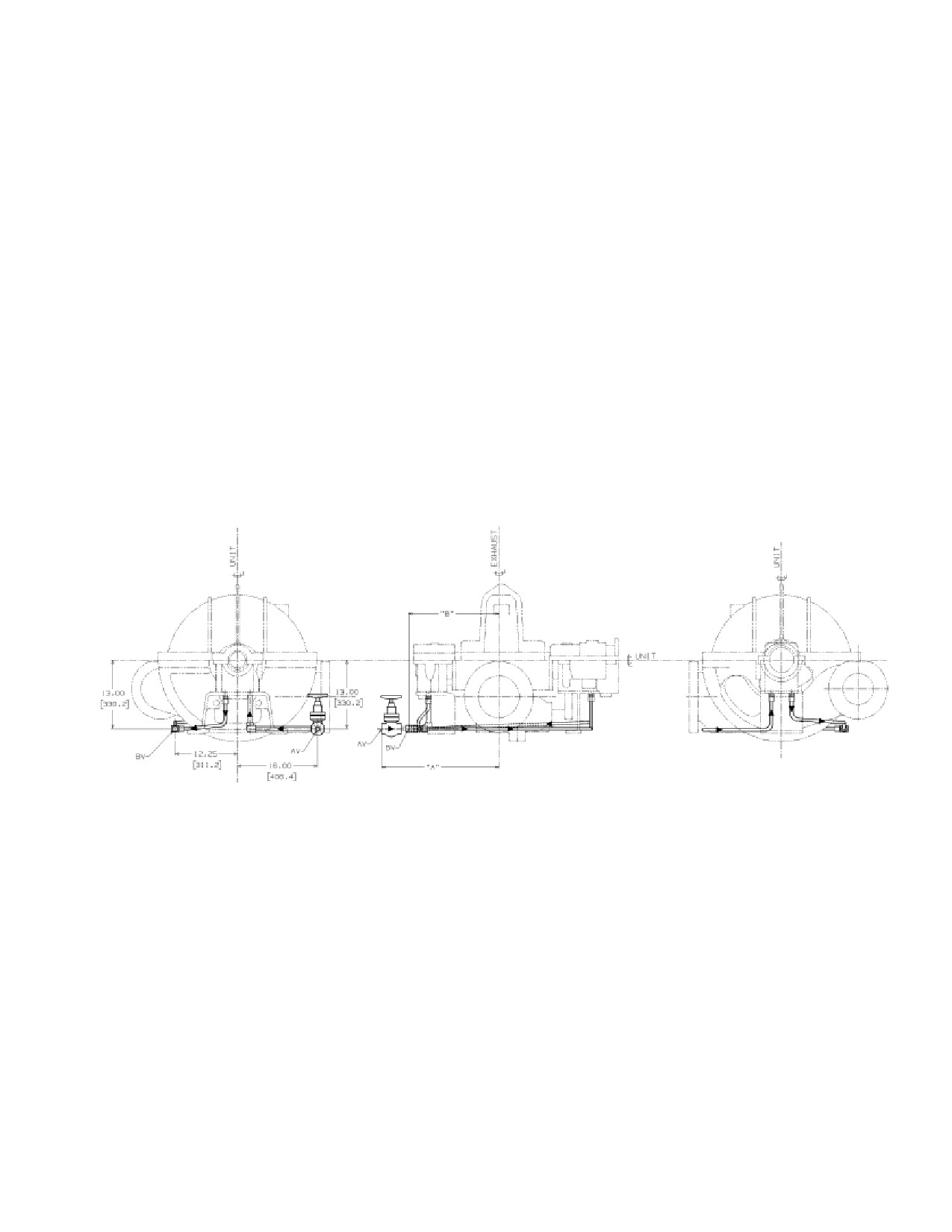
Valves should be included in the cooling water piping to control the flow of water
and allow it to be shut off. The ideal system would employ two valves—one
128
Lubrication System
upstream of the bearing housing, acting as a shut-off valve, and one downstream to
control flow. This arrangement ensures that water jackets are filled with water and
allows water to be shut off without disturbing the flow adjustment. If one valve is
used, it should be downstream of the bearing housings.
Figure F-1.Typical Bearing Case Water Piping Schematic for Ring Oiled
Turbines
Flow should be adjusted to maintain bearing oil sump temperature in the normal
range shown in Table F-3, Recommended Oil Sump and Bearing Temperatures.
Refer to the certified drawings in Appendix A for the location of cooling water
connections on bearing housings.
129
Single stage ring oiled turbines require cooling water connections to the bearing
cases. See Figure F-3 for a typical bearing case water piping schematic for ring
oiled turbines.
Pressure Lube Turbines -- The cooling water connections to the oil cooler are
shown on the Outline Drawing or Oil Piping Diagram in Appendix A. The turbine
data sheets specify the required volume. The water outlet piping should be ar-
ranged to discharge into an open sight drain where the operator can observe it. A
water leg of at least six inches in height should be placed in the outlet line adjacent
to the cooler to assure the cooler being kept full of water.
F.7.1
Bearing Housing Cooling Water Requirements
Cooling water for bearing housings must meet the following specifications.
Flow Rate (per housing):
2 GPM (7.0 l/MIN)
Maximum Inlet Pressure:
100 PSIG (690 KPAG)
Maximum Inlet Temperature
90F (32C)
Water Quality:
Clean, non-corrosive
F.7.2
Governor Oil Cooling Water Requirements
Refer to turbine data sheets for water requirements. During operation, admit cooling water
as necessary to maintain oil temperature, out of cooler, between 90°F and 180°F (32°C
and 82°C).
F.8
Recommended Oil Sump and Bearing Temperatures
Table F-3, Recommended Oil Sump and Bearing Temperatures, lists the
recommended temperature ranges for the turbine bearing oil sumps and the turbine
bearings during normal operation. In addition, the table defines recommended
alarm and trip set points for optional instrumentation.
Oil Sump Temperature—
Bearing Temperature—
Operating Status
F
C
F
C
Normal Operation
180
82
220
104
Alarm
185
86
230
110
Trip
195
90.5
250
121
Table F-2. Recommended Oil Sump and Bearing Temperatures
130
Lubrication System
For turbines operating in an extreme environment, an optional thermostatically
controlled immersion heater may be provided in the main oil tank to heat the oil prior
to start-up and to maintain a suitable temperature during operation. If your turbine
has this equipment, a supplementary description and parts list is provided in Appendix
B. Operating procedures for this equipment are given in Section A-12.
When ambient temperature is approximately at the freezing point 32°F (0°C) or
below, the thermostat should be set at its maximum heat setting prior to startup. The
heater selected by Dresser-Rand is limited to approximately 250°F (121°C) so that
there is no danger of carbonizing the oil.
When oil reaches a temperature where it will flow smoothly, approximately 100°F
(38°C) it should be circulated through the oil system. If the oil tank is not equipped
with a thermometer, the temperature may be monitored as the oil leaves the system
cooler. The cooling water for the oil cooler should not be turned on until the turbine is
operating and the temperature of the oil leaving the cooler is approximately 120°F
(49°C). After oil pressure is established and stabilized throughout the complete system, the
turbine may be started, as described in the Starting Procedure. During operation, the
thermostat may be initially set at its minimum setting. Periodic checks of the oil tempera-
ture can determine the requirement for adjustment.
Governor Heater--When ambient temperature is approximately at the freezing
point, 32°F (0°C) or below, the thermostat should be set at its maximum heat setting prior
to startup. When the oil in the governor reaches approximately 90°F (32°C), the
turbine may be started and the thermostat set at its minimum heat setting. It should
be noted that precise temperature of the oil for normal operation of the governor is not
critical, provided that the oil temperature is within the range of 90°F to 180°F (32°C to
82°C).
CAUTION
Do not allow COOLING WATER to COOL OIL SUMP
TEMPERATURE TO BELOW 130F (54C), as this may
interfere with the action of the oil rings or cause
ATMOSPHERIC MOISTURE to CONDENSE in the oil
reservoir.
F.9
Constant Level Oiler
Turbines lubricated with oil rings typically are equipped with constant level oilers.
The purpose of these oilers is to maintain the correct oil level in the bearing
housings. When applicable, instructions for constant level oilers may be found in
Appendix B.
131
F.10
Bearing Housing Oil Levels and Capacities
The following table shows the approximate oil quantities required to fill bearing
housings based on the SST turbine frame size. In addition, each constant level oiler
has a capacity of about 8 oz. of oil.
Frame Size
Steam End Capacity
Exhaust End Capacity
ALL SST’S
64 oz. (1.89 l)
64 oz. (1.89 l)
Table F-3. Bearing Housing Oil Capacity
The following table shows the required oil levels that should be maintained by
proper adjustment of constant level oilers. The oil level gauge on the side of the
bearing housing indicates the oil level. A mark inscribed on the lower-half bearing
housing indicates the proper oil level. If the mark is obscured, refer to the
following table.
Distance Below Bearing Housing
Frame Size
Horizontal Split in Inches
SST Simple Bearing Case Steam End
3.25 (8.26cm)
SST Simple Bearing Case Exhaust End
2.875 (7.30 cm)
Table F-4. Bearing Housing Oil Levels
For hydraulic governor oil requirements, refer to the governor instruction manual
in Appendix B.
F.11
Maintenance/Oil Changes
Oil levels in turbine bearing housings, the governor and/or optional oil reservoirs
should be checked daily.
Low point drains in bearing housings and oil reservoirs should be checked weekly
for water.
Establish an oil change frequency based on oil tests. Otherwise, oil in bearing
housings and oil reservoirs should be changed monthly; or earlier, if there is reason
to believe that the oil has been contaminated with water, dirt, or by overheating.
CAUTIONS
132
Lubrication System
The presence of oil in the constant level oilers does not
necessarily mean that oil in the bearing housings is at the
proper level.
CLEANLINESS is ESSENTIAL for long and trouble free service
from BEARINGS and the GOVERNOR. Care must be taken to
ensure that no foreign material enters bearing housings, the
governor, and constant level oilers or oil reservoirs when
performing maintenance, checking oil, adding oil, or making
adjustments.
For hydraulic governor oil requirements, refer to the governor instruction manual
in Appendix B.
F.12
Lubricating Oil Selection Guidelines
Reference Table F-6 -- Sleeve Bearing Turbine, Lubricating Oil Selection
Guidelines.
Reference Table F-7
- Ball Bearing Turbine, Lubricating Oil Selection
Guidelines
The importance of using a proper lubricant cannot be overemphasized. High
quality turbine oils are required. Dresser-Rand Steam Turbine Business Unit does
not recommend specific brands of oil. Turbine owners should consult reliable oil
suppliers regarding the proper selection of turbine oils. As a minimum, the selected
oil should be of premium quality rust and oxidation inhibited turbo-machinery oil,
which will readily separate from water and have minimum tendency to emulsify or
foam when agitated at actual operating temperatures. EP additives are not
recommended. Since the proper grade of lubricant may not be available locally, it
should be ordered in advance of start-up time. Comparisons between different
viscosity grading systems are shown in Table F-6, Viscosity Comparisons.
CAUTION
For SST turbines sharing a forced-feed lubrication system with
a gear reducer or driven equipment, refer to the certified
drawings in Appendix A for a description of the lubricating oil
requirements.
Viscosity Requirements
133

VISCOSITY SSU
DESCRIPTION
VALUES @ 100°F
Range
Nominal
*Light Turbine Oil (LTO)
ISO VG 32
130-180
150
**AGMA 1 / SAE 10W {Med)
ISO VG 46
193-235
214
***AGMA 2 /SAE 20
ISO VG 68
284-347
315
****AGMA 3 / SAE 30
ISO VG 100
417-510
464
Typical Recommendations
* Pressure Fed Lubrication
** Pressure Fed Lubrication with Oil Rings Retained
*** Ring Oiled Lubrication or Units with Reduction Gear.
**** Mist Oil Lubrication or Units with Ball Bearings
Table F-5. Viscosity Comparisons
F.13
Air Purge of Bearing Housings
An air purge connection can be furnished as an option on the bearing housing for
the supply of low pressure, dry, filtered air or nitrogen. The positive pressure
(relative to atmospheric pressure) will prevent the intrusion of dust, moisture, and
other contaminants into the bearing housing. The supply pressure should not
exceed a 1-inch (25.4 mm) water column.
134
Optional Gland Condensers, Eductors, and Ejectors
Section G
Optional Gland Condensers, Eductors, and
Ejectors
For some applications, optional ejectors, eductors or gland condensers may be
supplied with the turbine package for the removal and recovery of leakage past the
turbine shaft seals.
Motive flow is applied to the inlet of the educator or ejector, creating a slight
vacuum, which is applied at the turbine gland leak-off connections. The discharge
of the eductor, ejector and/or gland condenser is then typically returned to the
plant water system when the motive fluid is steam or a safe area when the motive
is fluid gas. These items normally ship loose for piping and installation by others.
Refer to the certified drawings and optional equipment manuals for details of any
items supplied with the turbine package.
Revision
A
135
THIS PAGE WAS LEFT BLANK
INTENTIONALLY
136
Optional Instruments and Controls
Section H
Optional Instruments and Controls
NOTE
Refer to Appendix B at the end of this manual for instructions
for accessory instruments and controls not manufactured by
Dresser-Rand.
H.1
Sentinel Warning Valve
If specified as an accessory (applies to turbines to be operated on steam only), the
turbine will be furnished with a sentinel-warning valve to alert the operator when
excessive pressure arises in the exhaust casing.
WARNINGS
The SENTINEL WARNING VALVE will ONLY WARN that
excessive pressure exists in the casing. It will NOT RELIEVE
THIS PRESSURE.
It is the USER’S RESPONSIBILITY to INSTALL A FULL-FLOW
RELIEF VALVE in the exhaust line between the turbine
exhaust casing and the first shut-off valve. This relief valve
should be sized to relieve the FULL AMOUNT OF STEAM
THAT THE TURBINE WILL PASS, in the event that the
exhaust line is blocked.
H.2
Pressure and Temperature Gauges
If specified as accessories, the turbine will be furnished with inlet and exhaust
pressure and/or temperature gauges. Inlet and exhaust gages must be connected to
the user’s inlet and exhaust steam piping just upstream and/or downstream of the
turbine inlet and exhaust flange connections as appropriate. Steam chest pressure
137
Optional Instruments and Controls
gages may be connected to a “T” connection installed into the turbine steam chest
drain piping. Gauges are maintenance-free and require no attention.
H.3
Solenoid Trip
WARNING
If the turbine is equipped with a solenoid overspeed trip system
it will be activated electrically, hydraulically, pneumatically or
with a combination of these power sources. If the required
power source is not activated or fails, the over-speed trip
system will not operate. The turbine cannot be tripped by this
system.
When specified, the turbine can be supplied with a solenoid operated trip system
for remote trip functions. The supplied components may include a solenoid
actuator, or a solenoid valve and pneumatic actuator. The action of the actuator
striking the turbine trip linkage disengages the knife-edges in the turbine trip
linkage, causing the overspeed trip valve to close. Trip signals to the solenoid can
be automatically or manually transmitted. Electrical power (and for systems with
pneumatic actuators air pressure) must be available for the operation of the remote
trip functions. Turbines may also include optional mechanical or proximity type
limit switches, which may be wired to signal a “turbine tripped” condition. Refer to
the certified drawings and appropriate vendor instruction manuals for specifics of
the trip system supplied with the Dresser-Rand equipment package.
Refer to turbine data sheets to determine whether solenoid valve trips out turbine (opens)
in energized or de-energized mode. Make sure valve is closed before starting.
H.4
Other Optional Instruments and Controls
When specified by the customer, other optional instruments and controls can be
supplied. Refer to the certified drawings and appropriate vendor instruction
manuals.
138
Start-Up and Operation
Section I
Start-Up and Operation
I.1
Warnings
The operator should read Sections A through H of this manual to become familiar
with the turbine before attempting to start and operate it.
WARNINGS
The surface temperature of the turbine and piping will become
that of the steam inlet temperature. This could exceed the
ignition temperature of some gasses. Therefore, if the turbine
is installed where explosive gasses could be present it is the
user's responsibility to insure that this does not create a
hazardous situation.
DO NOT START OR OPERATE this turbine unless the
INSTALLATION has been VERIFIED TO BE CORRECT and
all pre-startup SAFETY AND CONTROL FUNCTIONS have
been CHECKED.
DO NOT START OR OPERATE this turbine unless you have a
COMPLETE UNDERSTANDING of the location and function of
ALL COMPONENTS in the steam supply and exhaust
systems, including block and relief valves, bypasses, drains,
and any upstream or downstream equipment that may affect
the flow of steam to or from the steam turbine.
Should an explosion occur in the vicinity of the turbine it is the
user/installer’s responsibility to halt it immediately and/or limit
the range of explosive flames and explosive pressures to a
sufficient level of safety.
DANGERS
139
Start-Up and Operation
NEVER WEAR NECKTIES OR OTHER LOOSE CLOTHING
while in the proximity of the turbine or auxiliary equipment.
These could be become entangled in the shaft, couplings,
linkage or other moving parts and cause serious injury.
Keep body parts
(fingers, hands, etc.) away from shaft,
coupling, linkage or other moving parts to prevent contact and
possible serious injury.
Wear proper eye protection when working on or around the
turbine.
WARNING
Never operate the turbine with the governor or governor
system disabled.
CAUTION
If the ambient temperature exceeds
110F (43C), cooling
water must be provided to the bearing housings to limit the
maximum temperature of the lubricating oil to 180F (82C). If
the ambient temperature falls below freezing a means must be
provided to maintain the lubricating oil in the bearing housings
to a minimum temperature of 130F (54C) and to prevent
cooling water from freezing and possibly cracking the bearing
housings.
DANGER
140
Start-Up and Operation
NEVER BLOCK OR DISABLE THE TURBINE TRIP SYSTEM
OR ATTEMPT TO ADJUST OR REPAIR IT WHILE THE
TURBINE IS OPERATING.
WARNINGS
DO NOT START OR OPERATE this turbine unless you have a
COMPLETE UNDERSTANDING of the CONTROL SYSTEM,
the OVERSPEED TRIP SYSTEM, the drain and leak-off
systems, the lubrication system, and all auxiliary mechanical,
electrical, hydraulic and pneumatic systems, as well as the
meaning and significance of all monitoring gages, meters,
digital readouts, and warning devices.
When STARTING the turbine, be prepared to execute an
EMERGENCY SHUTDOWN in the event of FAILURE of the
GOVERNOR, OVERSPEED CONTROL SYSTEMS, linkage, or
valves.
The surface temperature of the turbine and piping will become
that of the steam inlet temperature. Personnel should wear
gloves and protective clothing to avoid burns.
141
Start-Up and Operation
CAUTIONS
Overloading the turbine drive shaft will cause the turbine to
slow down - possibly resulting in insufficient lubrication and/or
reduced function and damage to the driven equipment.
Turbines should not be subjected to temperatures in a non-
running ambient condition of less than 20°F (unless special
LOW TEMPERATURE has been specified and low
temperature materials have been provided.
Do not operate the turbine above the Maximum Continuous
Speed or below the Minimum Allowable Speed as shown on
the nameplate, for sustained periods of time.
WARNINGS
The turbine should NOT BE OPERATED unless a properly
sized, functional, FULL FLOW RELIEF VALVE or other
overpressure protective device has been installed UPSTREAM
OF THE SHUT-OFF valve closest to the TURBINE EXHAUST
LINE.
VERIFICATION of proper FUNCTIONING and SETTING of the
OVERSPEED TRIP SYSTEM during initial start-up is
MANDATORY. This should be accomplished with the turbine
disconnected from the driven equipment.
142
Start-Up and Operation
WARNINGS
Shown below are turbine noise levels that were measured at
three feet
(1 meter), while operating at a normal load and
exhausting to a positive back pressure. These noise levels are
not guaranteed and are published for informational purposes
only.
This noise data is based on test measurements that were
taken on similar equipment being operated on the factory test
stand, and have been extrapolated and/or corrected for
background noise as appropriate.
When the turbine is operated under actual field conditions,
noise generated in or by the piping, foundation, base plate,
couplings, driven equipment, background and other sources,
can add significantly to the turbine noise level and to the
overall noise levels in the area.
It is recommended that the equipment user assess the noise
level(s) of the completed installation and determine if additional
sound attention and/or hearing protection for operating
personnel is required.
Octave Band Frequency (HZ) - Expected Sound Pressure Levels
(dB - Ref. 2 x 10⁻⁵ N/m2)
Accoustic
63
125
250
500
1K
2K
4K
8K
Expected Overall dBA
Insulation
YES
96
91
88
86
83
82
81
81
85
NO
97
92
90
89
87
85
84
84
88
Table I-1. Turbine Sound Level Data
143
Start-Up and Operation
I.2
General
The following recommended start-up and operating procedures apply to the basic
turbine (ring-oiled, TG governor, without reduction gear). For information on any
optional equipment, refer to the appropriate vendor instruction manual in Appendix
B.
WARNINGS
None of the recommended start-up and operating procedures
contained in this manual shall be construed in any way as
relieving the user of his responsibility for compliance with the
requirements of any regulatory body, or for the exercise of
normal good judgment in the start-up, operation, and care of
the turbine.
If a coupling guard is to be installed, refer to the coupling guard
manufacturer’s instructions to insure that it does not contact
the running shaft or coupling which could cause a spark that
could ignite hazardous gasses in the environment in which the
turbine is installed.
To ensure trouble-free operation, the turbine must be:
a. Cleaned thoroughly prior to start-up and kept clean at all times.
b. Properly lubricated at regular intervals.
c. Subjected to regular checks for the correct functioning of protective devices.
d. Regularly inspected and maintained according to a scheduled preventive
maintenance program.
e. Operated according to the procedures specified in this instruction manual.
144
Start-Up and Operation
I.3
Turbine Installation and Start-Up Checklist
The following turbine installation and start-up checklist is provided as a guide on
the following pages. Although intended for use by Dresser-Rand servicemen, this
checklist is suitable as a guide for end-users as well.
Turbine Installation and Start-Up Checklist
I.3.1
Turbine Information
Customer
_________________
Location
______________
Serviceman
_________________
Customer Contact
______________
Start Date
_________________
Complete Date
______________
Nameplate Data:
Driven Equipment
Serial Number
_________________
__________________
Rated Speed [RPM]
_________________
__________________
Overspeed Trip [RPM]________________
__________________
Power [HP]
_________________
__________________
Governor
Lube System
Manufacturer
_________________
__________________
Serial Number
_________________
__________________
Part Number
_________________
__________________
Application:
Use:
Continuous _______ Standby _________Autostart _________
145
Start-Up and Operation
I.3.2
Site Information
Actual Steam Conditions:
Inlet press. (P1) ______Inlet Temp. (T1) ______Exhaust press. (P2) _____
Yes
No
Is the base provided level and adequate to support the turbine?
Is piping deadweight supported by hangers or supports?
Do inlet and exhaust flanges line up with piping flanges?
Does the steam inlet pipe have a top take-off from the main
header to minimize moisture induction?
Is there a piping run or dead leg beyond the take-off?
Have expansion joints been used?
Has the piping been blown out with steam (including exhaust
for backpressure units)?
Has inlet and exhaust piping been drained at low points or
trapped to avoid water legs?
Has a full-flow relief valve been installed in the exhaust system
upstream of the first shut-off valve? Setting? ___________
146
Start-Up and Operation
I.3.3
Yes No
Is the turbine in good condition without signs of improper storage,
mishandling or shipping damage?
Are foundation and base plate securing bolts adequate?
Is the turbine properly secured to the base plate?
Has the base plate been grouted?
Was rust preventative removed from the shaft and other exposed
surfaces?
If the turbine was prepared for long-term storage, was the inside of
gland housings wiped clean and carbon ring sets installed?
If a sleeve bearing type turbine was prepared for long-term
storage, was the bearing and shaft journal surface wiped clean?
Were bearing housings flushed and drained with a light oil prior to
filling?
Are lubricating oil levels correct?
Governor
Lubricating Oil Used:
Turbine --
Brand _______________
Type __________
Governor --
Brand _______________
Type __________
Is the coupling properly lubricated and free to oscillate by
hand?
Does the turbine rotate freely when turned by hand?
Do the oil rings rotate with the shaft?
Is the turbine rotation correct?
147
Start-Up and Operation
Yes
No
Do the throttle valve, overspeed trip valve and associated linkage
move freely?
Does the Overspeed Trip lever reset easily and trip when operated
by hand?
Does the emergency weight move freely in the governor cup
assembly?
Has the lube system been site flushed?
Are lube oil return lines pitched to the sump?
Is there a Sentinel warning valve?
Setting? _________
Is the turbine adequately drained at all points?
Are water-cooling lines to the bearing housings properly installed?
Are there provisions for regulating cooling water flow?
Are steam leak-off connections piped correctly and unrestricted?
(I.e., with no valves, manifolds, water legs or pipe size reduction).
Does the user understand the following:
Overspeed Trip System operation?
Overspeed Trip Valve reset procedure?
Overspeed Trip exercising requirement and procedure?
148
Start-Up and Operation
I.3.4
Start Up - Uncoupled
Drive shaft run out? ________ Driven equipment shaft run out? __________
Cold alignment method? (attach print out if available)
Rim & Face
( )
Reverse Indicator
( )
Laser
( )
Other
( )
RIM
FACE
Indicator mounted on _______________ coupling reading ________________
Turbine ___________________ inches low to driven equip.
Coupling Manufacturer _________________ Model ________
Yes No
Did governor operate properly?
Is the running speed satisfactory?
Trip speed checks #1 _______ #2 ________ #3 ________ RPM
Overspeed test witnessed by _______________________
Bearing oil temp (sump) Gov end _______ Drive end__________
Lube oil pressure to bearing ________ psig
Lube oil temp- Into Cooler ___________ Out ____________
Are protective devices operating properly?
149
Start-Up and Operation
I.3.5
Start Up - Coupled
Actual Steam Conditions:
Inlet press. (P1) ______
Inlet Temp. (T1) ______Exhaust press. (P2) _____
Yes
No
Does the turbine operate at rated speed?
Speed variation? _____________ RPM
Does auxiliary equipment operate properly?
Is steam leakage within acceptable limits?
Vibration: (in/sec)
(mils) filtered unfiltered
(Indicate speed if mils are used __________ rpm)
(Vert/Horiz/Axial)
Gov Bearing
___/__/___
Coupling Bearing
__/___/___
Driven equipment
Driven End Bearing
___/___/__
Non-Driven End Bearing
___/___/__
Are oil levels correct with no evidence of leakage?
Oil temp at discharge? Gov. End
_______ Drive End
________
Hot alignment method? (attach print out if available)
Rim & Face
( )
Reverse Indicator
( )
Laser
( )
Other
( )
RIM
FACE
Indicator mounted on _______________ coupling reading ________________
Turbine ___________________ inches low to driven equip.
150
Start-Up and Operation
Yes No
Were piping changes required to correct hot alignment readings?
To turbine? Describe ___________________________________
To driven equipment? Describe __________________________
Is turbine doweled to baseplate?
Is driven equipment doweled?
Was a copy of this report left with the customer?
Comments:
151
Start-Up and Operation
I.4
Start-Up Procedure
WARNING
Turbine installation, operation, repair and service must be
performed by EXPERIENCED PERSONNEL ONLY. Read and
understand this instruction manual before installing, operating,
repairing or servicing turbines.
I.4.1
Restoration of Turbine from Shipping Condition
The turbine was completely assembled, adjusted for proper operation, and tested
immediately prior to shipment. A quick reference check list of tasks to complete prior
to placing the unit into operation is as follows: (Storage information is provided at the
end of this section.)
Unpacking and inspection
Cleaning of shipping preservatives
Selecting and preparing foundation
Bearing inspection and seal oil baffle outside diameters
Aligning turbine and driven machine
Connect steam and exhaust piping
Connect water piping
Preparation for initial starting and start-up
We recommend that Dresser-Rand Service Representatives oversee the installation and
initial start-up of this steam turbine unit.
Before starting a turbine for the first time, or one that has been in storage, it is
important to have the bearing cases, shaft packing areas, and the governor parts
clean. Solvent may be used for this purpose.
(See Commercial Products for
Dresser-Rand Service List at the end of section
After factory testing, turbines are prepared for shipping and storage. The following
two sections describe activities to be performed prior to initial start-up.
I.4.1.1
Flushing/Filling of Bearing Housings
Before starting the turbine for the first time, open bearing case drains and allow
any residual oil to drain. Close the drains.
The oil recommended for permanent operation should now be added to the turbine
through the oil hole covers, until levels reach their respective permanent marks on
152
Start-Up and Operation
bearing housings. Add oil as necessary to constant level sight feed oilers mounted
at each bearing case. Note that a low oil level may result in improper lubrication
and a high oil level may cause leakage past the seals and/or overheating.
Refer to Section F, Lubrication System, for oil recommendations.
I.4.1.2
Shaft Packing
If the turbine was prepared for short-term storage, then no additional steps are
required.
For turbines in long-term storage, the upper half of the turbine case must be
removed to gain access to the shaft packing and turbine rotor. The garter springs
and stop washers should be wiped clean to remove the rust preventative. Matched
carbon ring sets (shipped with the turbine) should be installed. Labyrinth and
carbon ring seals, the inside of the turbine case and all internal components should
be cleaned of the water-soluble preservative.
I.4.2
Initial Start-Up Procedure
The following recommended start-up procedure applies to the basic turbine (ring-
oiled, TG governor, without reduction gear). For information on any optional
equipment, refer to the appropriate vendor instruction manual.
On ring-oiled units, the oil should be warmed up to a viscosity such that the oil rings will
turn and pick up oil; this may be done by circulating hot liquid through the water jackets,
or by means of electric heating elements in the oil compartments. On units equipped with a
flood lubricating system the oil should be warmed up to a viscosity such that the oil
pump will pick up its prime; this may be done by means of a steam heating coil or an electric
heating element. If electric heating elements are used, they should be limited to
approximately 250°F. temperature, to avoid carbonizing the oil. After the oil is warmed up,
circulate some of the warm oil by means of a hand, motor or steam driven pump.
It may not be necessary to pre-heat the oil unless the ambient temperature is well below 32°
F, depending on the relationship between temperature and oil viscosity. Experience will
determine the temperature at which it is necessary to preheat the oil.
After heating the oil or determining that it does not require heating, start the unit in
the usual manner, taking special care that all drain valves are left open long enough
to drain all condensed steam from the steam line and the turbine. Turn the unit over
slowly for a short time, making sure that the oil rings are turning and/or the oil
pump is delivering oil.
Before connecting steam piping to the turbine for the first time, all piping should
be thoroughly blown out with steam to ensure that solid particles such as welding
153
Start-Up and Operation
beads and rust are not carried along with the steam inlet into the turbine. Refer to
Section C, . Thereafter, the following precautions must be taken:
a.
Review warnings outlined in Section I.1. If this is the first time the turbine is
put in service, review the Installation Start-Up Checklist in Section I.3.
b.
Check the driven machine and verify that it is ready to start.
c.
Check oil levels in bearing housings and the governor.
d.
Verify that the magnetic pick-up to signal gear clearance is correct
(if
supplied).
e.
Verify that all valves downstream of the exhaust-isolating valve are open.
f.
On condensing units, admit sealing steam to carbon ring glands.
g.
For turbines supplied with gland leak-off connections, open the leak-off
atmospheric valve. Refer to Section C.3.12 , Gland Seal Intermediate Leak-
Off Piping-High Back Pressure Exhaust
h.
Open the exhaust-isolating valve.
i.
Open all hand-valves.
j.
Drain all condensate from low points in the inlet steam line, from the casing or
low points in the exhaust steam line, and from overspeed trip and throttle
valve bodies. Drain valves may be left open while the turbine is started, to
allow condensate to drain as the turbine warms up.
k.
If a cooling water system is used, admit cooling water to bearing housing
water jackets. Flow should be adjusted to maintain bearing oil sump
temperature in the normal range, as shown in Table F-3, Recommended Oil
Sump and Bearing Temperatures. Refer to Section F, Lubrication System.
l.
If a gland seal condenser is used, admit cooling water. If a steam ejector or
water eductor is used, admit the motive flow.
m.
Start the lubrication system, if applicable.
n.
Verify that the overspeed trip valve is latched open, by raising the manual
reset handle.
154
Start-Up and Operation
DANGER
NEVER BLOCK OR DISABLE THE TURBINE TRIP SYSTEM
OR ATTEMPT TO ADJUST OR REPAIR IT WHILE THE
TURBINE IS OPERATING.
o. Provide a means for measuring turbine speed, either with a tachometer or with
a stroboscope.
WARNING
Never operate the turbine with the governor or governor
system disabled.
p. Turn the governor-adjusting screw on the end of the governor fully
counterclockwise to the low speed position. Refer to Figure D-1, Woodward
Oil Relay Governor Features, for screw location.
q. Admit sufficient steam through the inlet-isolating valve to turn the turbine
over slowly (950 RPM minimum) and continue to operate at this speed until
the turbine is fully warmed. Close all drain valves when condensate no longer
drains. Some of the incoming steam will condense on the “cold” turbine walls.
CAUTIONS
DO NOT RUN turbines equipped with oil ring lubrication at
speeds LESS THAN 950 RPM. The OIL RINGS WILL NOT
OPERATE CORRECTLY at these speeds, causing BEARING
FAILURE due to lack of lubrication.
Do not operate the turbine above Maximum Continuous Speed
or below Minimum Allowable Speed as shown on the
nameplate, for sustained periods of time.
r.
Listen for uneven running or vibration. Shut down and correct, if required.
Refer to Section I.5, Turbine Vibration Limits, when measuring shaft axial
displacement, shaft radial displacement, or bearing housing vibration.
s.
Open isolating valve in the inlet steam line gradually, bringing turbine speed
up slowly until the governor takes control at the low speed setting. If the
governor has not assumed speed control by the time rated speed is reached,
shut down immediately and refer to Section K, Troubleshooting.
155
Start-Up and Operation
t.
For turbines supplied with gland housing leak-off connections, open the leak-
off isolation valve and close the leak-off atmospheric valve. Refer to Section
C.3.12, Gland Seal Intermediate Leak-Off Piping-High Backpressure
Exhaust.
u. Once speed control has been established, open the throttle valve by adjusting
the speed setting screw on the governor clockwise to bring the turbine up to
the required operating speed of the driven equipment.
v. Monitor turbine operation until stable operation is attained.
I.5
Turbine Vibration Limits
I.5.1
Shaft Displacement Measured with Proximity Probes
Radial Displacement:
When the turbine has been provided with provisions for radial proximity probes,
the turbine shaft has been burnished and degaussed at the probe locations to limit
the electrical and mechanical runout of the shaft. API 611 specifies that when the
turbine is brand new and operated on the factory test stand that the vibration level
must be at or below the “shop limit + runout”. Actual coupled, loaded field
conditions tend to be higher.
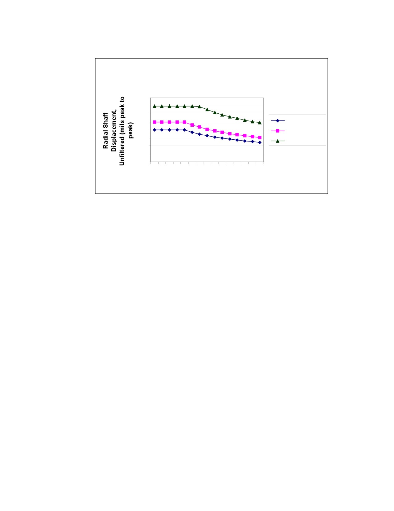
Radial displacement in any plane during coupled, loaded, field conditions should
be at or below the alarm level as shown in the figure below. If the level of
vibration increases to greater than the trip level, the turbine should be stopped and
the cause of the vibration identified and corrected.
156
Start-Up and Operation
Wellsville SST Vibration Limits/Settings for API-
611 and Non-API Units
4.0
3.5
3.0
Shop Limit
2.5
2.0
Alarm Setting
1.5
Trip Setting
1.0
0.5
0.0
1000
4000
7000
MCOS (RPM)
Figure I-1.
Radial Shaft Displacement
Axial Displacement:
For turbines provided with standard ball thrust bearings, the shaft axial position is
typically not measured. Refer to tables B-1, Major Fits, Clearances, & Rotor
Balance Criteria
- SST, and B-2, Major Fits, Clearances, & Rotor Balance
Criteria - for shaft endplay.
Turbines provided with tilting pad thrust bearings are designed to have some axial
clearance between the active and inactive thrust faces known as float. When these
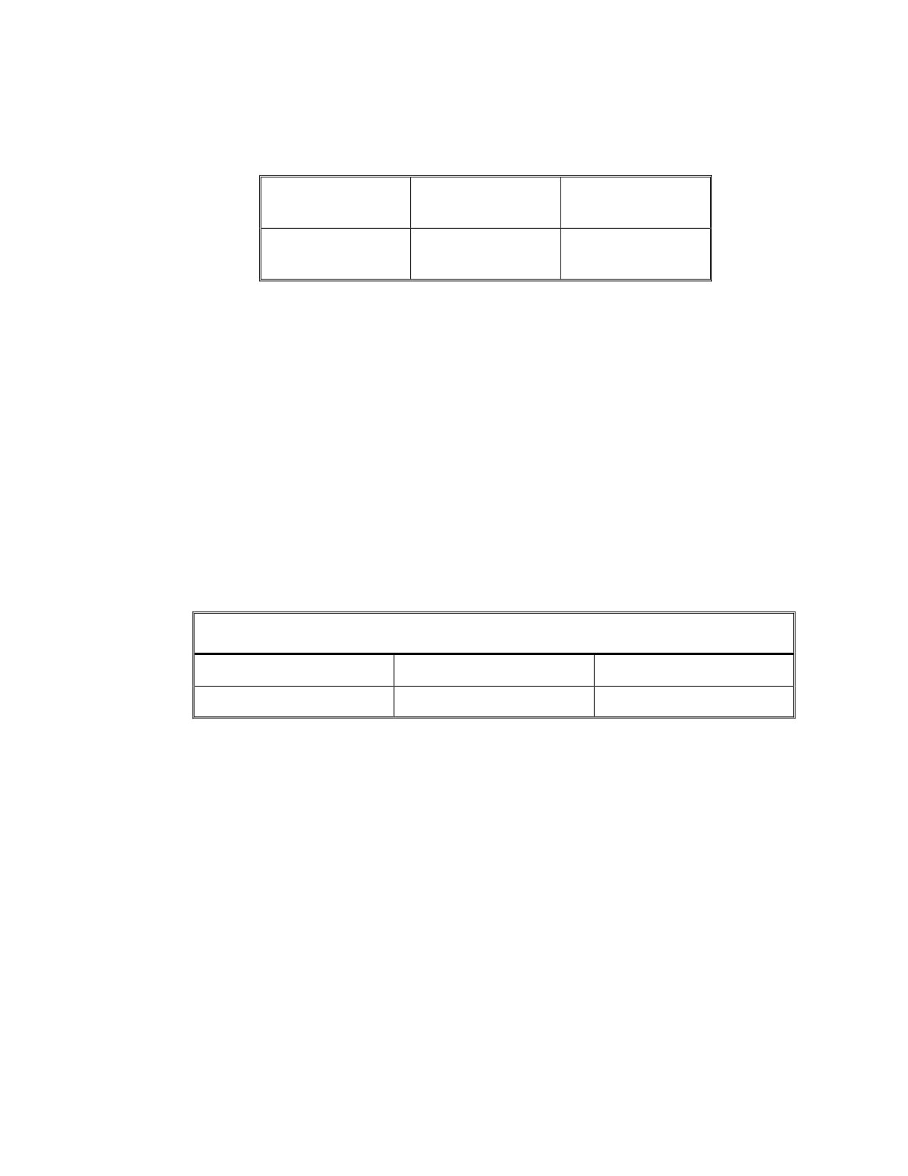
turbines have been provided with provisions for axial position probes, the Alarm
and Trip set points are specified in Table I-1, Axial Shaft Displacement Tilting Pad
Thrust Bearings. If the level of displacement increases to greater than the trip
level, the turbine should be stopped and the cause of the displacement identified
and corrected.
Note: For API 612 turbines the shop limit is 1.0 instead of 2.0.
157
Start-Up and Operation
Alarm
Trip
Model
ALL SST
+/- 17 mils
+/- 22 mils
MODELS
Table I-2. Axial Shaft Displacement Tilting Pad Thrust Bearings
I.5.2 Bearing Housing Vibration
When shaft proximity probes are not installed, the bearing housing vibration can be
used as an indirect measure of the shaft displacement.
API 611 and 612 specify that when the turbine is brand new and operated on the
factory test stand, the peak vibration measured on the bearing housing while it
operates at the maximum continuous speed shall not exceed 0.12 inches per second
[unfiltered] and
0.08 inches per second
[filtered]. When measuring bearing
housing vibration, the alarm and trip set points are specified in the table below. If
the level of vibration increases to greater than the trip level, the turbine should be
stopped and the cause of the vibration identified and corrected.
Bearing Housing Vibration [inches per second, unfiltered]
Turbine Model
Alarm
Trip
ALL SST MODELS
0.24
0.36
Table I-3. Bearing Housing Vibration
I.6
Testing the Overspeed Trip Mechanism
Refer to Section E.6, Testing the Overspeed Trip Mechanism.
I.7
Governor Speed Adjustment
Standard SST turbines are supplied with WOODWARD TG-type hydraulic
governors. Operating speed of the turbine is adjusted using the TG governor speed
adjustment screw, located in the cover plate of the governor. Refer to Figure D-1,
Woodward Oil Relay Governor Features, for adjusting screw location. The speed
adjustment mechanism is provided with sufficient internal friction to eliminate the
158
Start-Up and Operation
need to externally lock the screw. A screwdriver, coin, or key may be used to
adjust speed, and only light torque is required to turn the adjusting screw.
Turning the adjustment screw clockwise increases the turbine speed setting.
Exercise care when increasing the speed setting, to ensure that driven machine
speed limits or trip speed are not inadvertently exceeded as a result of such
increases.
Turning the adjustment screw counterclockwise decreases the turbine speed
setting. Continuous governing below
1100 RPM for the low-speed governor,
below 2200 RPM for the medium-speed governor, or below 4000 RPM for the
high-speed governor is not recommended because governor oil pressure may not
be sufficient to actuate the governor valve.
Optional construction may include alternate governor configurations. Refer to the
certified drawings and appropriate vendor manual for complete description.
I.8
Governor Droop Adjustment
For WOODWARD TG-type hydraulic governors, droop is factory adjusted to
provide a no-load speed of approximately 106% to 110% of the full-load or normal
speed. If it becomes necessary to alter droop from this initial setting, follow
instructions in the Woodward governor manual.
Exercise caution whenever the governor is opened. The TG governor is a precise
hydraulic mechanism, and the entry of dirt or any other foreign material can cause
the governor to malfunction.
Optional construction may include alternate governor configurations. Refer to the
certified drawings and appropriate vendor instruction manual for complete
description.
WARNING
159
Start-Up and Operation
GOVERNORS should NOT be DISMANTLED OR REPAIRED
by INEXPERIENCED PERSONNEL. Governors contain
powerful springs that could cause PERSONAL INJURY and
have delicate components which, if damaged, could result in
GOVERNOR FAILURE.
WARNING
FIELD CONFIGURABLE GOVERNOR
Any change to control limits, such as (but not limited to) speed,
overspeed trip, control logic, other than “tuning” (see governor
manual) requires the prior written approval of Dresser-Rand
Company to assure the safe operating limits are not exceeded.
Failure to comply may result in damage to property, serious
injury or death to personnel. Refer to the instruction manual for
detailed instructions.
I.9
Hand-valve Adjustments
SST turbines can, as an option, be fitted with up to three hand-valves (350 frame
turbines: 1; 500 and 700LP frame turbines: 2; and 700, 700H, and 700 HLP frame
turbines: 3). These hand-valves provide the operator with the ability to increase or
decrease the number of nozzles admitting steam to the turbine wheel.
The turbine will operate most efficiently when the pressure in the steam chest is at
a maximum (approximately 90% of line pressure). The highest chest pressure
occurs when the fewest number of hand-valves are open, which will allow the
desired operating speed.
To adjust hand-valves for maximum efficiency, proceed as follows:
With all hand-valves open and the normal load applied, adjust the governor to the
required operating speed. Beginning with the hand-valve farthest from the inlet
flange close one hand-valve at a time until the turbine speed falls off sharply. Then
reopen the last hand-valve that was closed. The speed should return to the required
value. If both hand-valves are closed and no sharp drop in speed occurs, leave both
hand-valves closed.
160
Start-Up and Operation
Caution: When putting the unit into operation, do not close a hand-valve tightly
until the turbine is up to operating temperature and all parts are evenly heated. The
reason for this is that the material of the valve stem is subject to greater thermal
expansion than the turbine casing, and if the valve is closed tightly when cold, it
may lock the valve in the closed position making it difficult to open.
CAUTION
Do not leave any hand-valve partially open, as this may result
in steam cutting of the valve and seat. Hand-valves should be
completely open or completely closed. Turbine speed should
not be controlled by the hand-valves; this is the function of the
governor.
I.10
Shutdown
The following recommended shutdown procedure applies to the basic turbine
(ring-oiled, TG governor, without reduction gear). For information on any optional
equipment, refer to the appropriate vendor instruction manual.
After the unit is shut down in accordance with normal operating routine, special
care should be taken to be sure that all water is drained from the steam line, ex-
haust line, turbine casing, valves, oil cooler, etc. Pockets of water could cause
damage due to freezing, and could cause trouble during the next start-up.
Shutting down the turbine may be accomplished as follows:
a. Check shutdown instructions for the driven equipment.
b. Trip the overspeed trip lever manually.
b. Close the isolating valve in the inlet steam line.
WARNING
Do NOT USE the OVERSPEED TRIP VALVE as a permanent
SHUT-OFF VALVE.
d. For turbines supplied with intermediate gland housing leak-off connections,
open the leak-off atmospheric valve and close the leak-off isolation valve.
Refer to Section C.3.12, Gland Seal Intermediate Leak-Off Piping-High Back
Pressure Exhaust.
161
Start-Up and Operation
f.
If cooling water is used, turn off cooling water to the bearing housings after
the turbine has cooled down, unless on standby or automatic start.
CAUTION
WATER-COOLING JACKETS must be DRAINED if there is a
possibility of FREEZING TEMPERATURES.
f.
Close the exhaust-isolating valve.
g. For condensing units, turn off sealing steam to carbon rings.
h. If a gland seal condenser is used, turn-off cooling water. If a steam ejector or
water eductor is used, turn-off the motive flow.
i.
Open all condensate drains.
j.
If the turbine is on standby service, or is to be shut down for an extended time
period, it should be started up, or at least turned over one or two times by
hand, once or twice each month to distribute oil to bearings, preventing rust.
k. Turbines in standby service, where bearing housing cooling water continues to
be supplied, must be checked periodically to ensure that moisture is not
condensing in the lubricating oil. Refer to Section F, Lubrication System.
WARNING
After operating the turbine, allow sufficient time for the turbine
to cool down prior to performing an inspection, repair or
maintenance function.
I.11
Restart Procedure
Before restarting the turbine, refer to Section I.1, Warnings.
I.11.1
Non-Condensing Turbines
162
Start-Up and Operation
The following recommended procedure applies to the basic turbine (ring-oiled, TG
governor, without reduction gear). For information on any optional equipment,
refer to the appropriate vendor instruction manual.
Use the following procedure:
a.
Check all oil levels. Fill lubricators as necessary. Start lube oil system, if
applicable.
b.
Place any controls, trip mechanisms, or other safety devices in their operating
positions.
c.
Open all drain valves on steam lines, turbine casing, and steam chest, and fully
open hand-valves, if furnished.
d.
Open the turbine exhaust-isolating valve.
e.
If cooling water is used, introduce cooling water to bearing housing cooling
chambers to prevent overheating. Cooling water flow should be adjusted to
maintain bearing oil sump temperature in the normal range, as shown in Table
F-3, Recommended Oil Sump and Bearing Temperatures.
f.
If a gland seal condenser is used, admit cooling water. If a steam ejector or
water eductor is used, admit the motive flow.
g.
Open the steam inlet isolating valve and bring the turbine up to desired speed.
h.
Make necessary governor adjustments to attain desired speed as load is
applied to the turbine.
i.
Close all drain valves when drain lines show the system is free of condensate.
j.
Close hand-valves, as appropriate, to attain maximum efficiency.
k.
Check bearing temperatures and overall operation for any abnormal
conditions.
l.
Monitor turbine operation until stable operation is attained.
I.11.2
Condensing Turbines
163
Start-Up and Operation
The following recommended procedure applies to the basic turbine (ring-oiled, TG
governor, without reduction gear). For information on any optional equipment,
refer to the appropriate vendor instruction manual.
Use the following procedure:
a.
Check all oil levels. Fill lubricators as necessary. Start lube oil system, if
applicable.
b.
Place any controls, trip mechanisms, or other safety devices in their operating
positions.
c.
Open all drain valves on steam lines, turbine casing, and steam chest, and fully
open hand-valves, if furnished.
d.
Turn on sealing steam to carbon rings. Open supply valve until a wisp of steam
flowing out of the outboard leak off is observed.
e.
If a gland seal condenser is used, admit cooling water. If a steam ejector or
water eductor is used, admit the motive flow.
f.
Open the turbine exhaust-isolating valve.
g.
If cooling water is used, introduce cooling water to bearing housing cooling
chambers to prevent overheating. Cooling water flow should be adjusted to
maintain bearing oil sump temperature in the normal range, as shown in Table
F-3, Recommended Oil Sump and Bearing Temperatures.
h.
For turbines supplied with intermediate gland housing leak-off connections,
open the leak-off atmospheric valve. Refer to Section C.3.12, Gland Seal
Intermediate Leak-Off Piping-High Back Pressure Exhaust.
i.
Open the steam inlet isolating valve and bring the turbine up to desired speed.
j.
Make necessary governor adjustments to attain desired speed as load is
applied to the turbine.
k.
Close all drain valves when drain lines show the system is free of condensate.
l.
Close hand-valves, as appropriate, to attain maximum efficiency.
m.
Check bearing temperatures and overall operation for any abnormal
conditions.
164
Start-Up and Operation
n. Monitor turbine operation until stable operation is attained.
I.12
Standby Operation
Turbines that are not running continuously are often in standby operation where
they must be ready to operate at any time with little or no advance notice. Turbines
in standby service must be capable of starting quickly and reliably in emergency
situations to prevent damage to large, costly systems, such as boilers or large
rotating machinery.
Turbines in standby operation present unique operational and maintenance
situations which must be understood and addressed. Listed below are the most
frequently encountered issues:
Need to prevent collection of condensate in piping, valves or turbine casing.
Such condensate could slug or otherwise damage the turbine.
Need to avoid thermal shock (casing and rotor stress) on rapid start-up.
The need to start quickly with little or no intervention or effort by an operator.
Avoidance of corrosion and fouling of control linkages, valves, glands,
packing, seals, etc., through lack of use.
Degradation of lubricant by leakage, oxidation due to excessive heat, or
contamination from water, condensate, dirt or chemicals.
Freezing of condensate or lack of lubrication due to extremely cold ambient
conditions.
Some methods and equipment employed to deal with the problems above are:
STEAM TRAPS - Steam traps are "smart valves" used in turbine drains and inlet
piping. Traps sense the presence of condensate and automatically open to allow it
to drain. When the condensate is drained the traps automatically close. Steam
traps are rated by pressure, temperature and flow. The amount of condensate
passed will vary, depending on the steam conditions and the steam piping design.
Steam traps should be valved to allow for maintenance and isolation. Manual
drains that bypass the trap are also recommended. When specifying steam traps
the highest pressure and temperature the trap might be exposed to should be taken
into account. This is often inlet pressure and temperature.
165
Start-Up and Operation
AUTO START VALVE - A valve in the inlet steam piping which can be
automatically and remotely opened to start the turbine. The auto start valve
actuation speed should be sufficiently slow to minimize thermal shock to the
turbine and to allow sufficient time for the turbine governor to establish speed
control.
BYPASS VALVE - A small valve typically used to pass a small amount of steam
around an auto start or isolating valve to provide warming and in some instances
slow roll of the rotor.
IDLING NOZZLE - A special nozzle, usually piped separately via a bypass
valve, that is optimally chosen to provide warming and slow roll of the rotor with
minimal steam consumption.
SLOW ROLL - The steam powered slow turning of a turbine rotor, usually
several hundred RPM. Slow rolling a turbine will maintain the bearings, seals and
carbon rings free and operable. It provides warming that will reduce thermal shock
on start up and prevents freezing of condensate. Slow rolling maintains lubricant
moisture free and flowing. Some types of driven equipment cannot be slow rolled.
When a turbine is slow rolled special considerations may be required for
lubrication depending on turbine design, lubrication design, speed, exhaust
temperature and ambient conditions. Consult factory if slow roll operation is under
consideration.
EXHAUST WARMING - A means of warming a turbine by closing the inlet
block or auto start valve and opening the exhaust isolating valve. This is only
effective when exhaust pressure is greater than atmospheric. Precautions are
necessary to prevent introduction of foreign material into the turbine via the
exhaust steam and excessive exhaust pressure that might exceed the turbine's rated
exhaust pressure. No slow roll occurs. Condensate must be drained or trapped
prior to auto starting.
When operating on standby, the following practices and precautions are necessary:
The turbine should be started periodically to verify that it is in proper
operating condition. This must include test and exercise of the overspeed trip
system.
Steam traps should be checked periodically to insure that they are operating.
An idling nozzle provides more efficient operation than a simple bypass valve
for slow roll.
166
Start-Up and Operation
To prevent excessive bearing temperatures, bearing housing cooling water
may be required during slow roll or exhaust warming operation.
Excessive cooling water flow during standby operation could cause
condensation to contaminate lubrication oil. Maintain bearing oil sump
temperature in the normal range, as shown in Table F-3, Recommended Oil
Sump and Bearing Temperatures.
Lubrication oil levels in the bearing housings and governor must be checked
periodically.
When a standby turbine is started, cooling water must be turned on if required.
Prior to start up, standby turbines must be drained of all condensate using
traps or manual valves.
The exhaust isolating valve on a turbine with auto start must be open at all
times to prevent over pressurization of the exhaust casing on start up.
When it is not possible to periodically operate or slow roll a standby turbine, it
should be periodically turned by hand.
If a turbine in standby operation is exposed to freezing temperatures,
provisions must be made to prevent damage and clogging of drains with
frozen condensate.
I.13
Auto Start Operation
If a standby turbine must be started quickly and automatically or from a remote
location, then the turbine must be equipped with an auto start valve and trapped
drains. The exhaust-isolating valve must be kept open.
Refer to Section I.12, Standby Operation, for additional information and
considerations.
Refer to Section C.3.14, Suggested Piping Schematics for Standard SST Turbines,
for additional information and considerations.
I.14
Manual Start Operation
If a standby turbine is to be started manually the inlet isolating valve is normally
closed, drains do not require steam traps and the turbine is put into service by
manually opening these valves.
167
Start-Up and Operation
Refer to Section I.12, Standby Operation, for additional information and
considerations.
Refer to Section C.3.14, Suggested Piping Schematics for Standard SST Turbines,
for additional information and considerations.
I.15
Quick Start
In some applications, it is desirable to start up the turbine rapidly. Auxiliary oil
pumps and boiler feed pumps are often called upon to start quickly in emergency
situations. In such applications, condensate ingestion (slugging) and thermal shock
to the casing and rotor are concerns. Piping should be carefully designed and
trapped to prevent accumulation of condensate upstream on the inlet. Turbine
drains should be trapped as well. A small amount of inlet steam should be bled into
the inlet line to heat the turbine. Exercise care to ensure that the line, supplying this
warming steam, is not large enough to supply enough steam to drive the turbine.
Exhaust back pressure can be used for this purpose as well. Refer to Section I.12,
Standby Operation, and I.13, Auto Start Operation, and I.15.3, General, for
additional information.
I.15.1
Acceleration Rate
With steam turbine applications that are started with no load, the acceleration rate of a low
inertia rotating element can be so high that the control system response to close the
steam admission valve does not react prior to overspeed trip. This is particularly true
of the turbine generator sets, which may also require limited frequency variations in the
electrical system. In instances such as this, a ramp effect on governor valve closure may
be built into the control system.
I.15.2
Temperature Differential
On turbines with built-up rotors, the disc-to-shaft allowance tends to decrease to
unacceptable limits with a 200°F (93°C) temperature differential between the disc
and shaft. The probability of such a condition existing is greater at approximately five
minutes after start-up, rather than immediately at start-up. Loss of shrink fit can result in
axial or wobble movement of the disc on the shaft, possibly resulting in turbine
breakdown. The colder the unit at start-up, the greater the probability of the temperature
differential occurring. Since the utilization of forged discs in lieu of plate discs allows a
higher shrink fit, we normally recommend the customer consider using forged discs.
Operate in accordance with normal operating routine; except that in maintaining suitable
lubricating oil temperature and viscosity, it may be necessary to heat the oil instead of
cool the oil.
168
Start-Up and Operation
On some types of turbine governors, a change in the oil viscosity has some effect on the
speed of the units; therefore, when operating a unit under varying oil temperature
conditions, it may be necessary to make manual adjustments on the speed governor.
I.15.3
General
The subject of "quick," "fast" or "automatic" start is not something new in the steam turbine
industry, nor has Dresser-Rand decreased its engineering standards for design of steam
turbine shafts, bearings, or shrink fit of discs to shafts.
In general, reliability and durability are compromised by quick starting a turbine and will
result in a shortened overall turbine life. Frequent quick starts are particularly severe on
bearings and rotating elements. The more rapid the acceleration rate, the higher are the
transient loads and the more severe are the loading effects.
Dresser-Rand single stage turbines with standard construction are suitable for start-up in
five seconds provided the following conditions are met:
1. The inlet side of the turbine steam line must be trapped.
2. Proper lubrication of bearings must be provided.
3. The inlet temperature of the steam shall not exceed 750°F (399°C).
4. The differential temperature between the inlet steam and exhaust steam shall not
exceed 350°F (177°C).
5. Back pressure shall be maintained on the casing during shutdown. (This in itself is not
a recommended operating condition due to possible wire cutting or carbon ring decay,
but will keep the casing warm.)
6. The operating speed of the turbine shall not exceed 6000 RPM.
7. The unit must be brought up under load.
In operating a turbine under the above conditions, the user must bear the responsibility
for bearing failure, loss of disc-to-shaft shrink fit, and carbon ring decay.
Dresser-Rand does not recommend quick starting turbines that are in locations
where the ambient temperature is less than 0F (-18C).
Units operating at very low ambient temperatures should be supplied with a
lubricating oil especially selected by a reputable oil company as being suitable for the
operating conditions. Special consideration should be given to insulating the entire
169
Start-Up and Operation
unit, including the lubricating oil lines and the oil tank (on units equipped with a flood
lubricating system), to avoid excessive heat losses and excessive condensation of steam.
I.16
Function Check of Sentinel Warning Valve
A sentinel warning valve (when provided) is mounted on the turbine casing to
warn of excessive exhaust pressure. It is not a pressure-relieving device. The
following test of this valve can be performed when the turbine is not running and
should be carried out at least yearly. The sentinel warning valve should be set to
operate just before the full-flow relief valve starts to open.
The sentinel warning valve can be tested as follows:
a. Close the inlet-isolating valve.
b. Open the exhaust-isolating valve.
c. Latch the overspeed trip mechanism.
d. Open exhaust casing drain valve two turns.
e. Slowly open inlet isolating valve until a little steam flow is visible from the
exhaust casing drain.
f.
Close the exhaust drain valve.
f. Slowly close isolating valve in exhaust line and observe pressure on a pressure
gauge mounted to the turbine casing, or in the exhaust line before the isolating
valve. The sentinel-warning valve should open at the pressure value stamped
on it.
CAUTION
DO NOT allow EXHAUST PRESSURE to EXCEED the
stamped setting value by more than 10 PSIG (69 kPag).
h. Relieve pressure in casing by rapidly and fully opening isolating valve in
exhaust line.
170
Start-Up and Operation
i.
Close the inlet-isolating valve.
j.
Open all drains.
k. If sentinel warning valve does not function properly, replace it and repeat the
above test procedure.
171
Maintenance, Maint. Sched. and Inspect. Sched
THIS PAGE WAS LEFT BLANK
INTENTIONALLY
172
Maintenance, Maint. Sched. and Inspect. Sched.
Section J
Maintenance, Maintenance Schedule and Inspection
Schedule
J.1
Introduction
The Dresser-Rand SST Turbine is a high-quality prime mover that has been
carefully assembled and thoroughly tested at the factory. As with any machinery,
the turbine requires periodic maintenance and service. This section discusses
periodic maintenance requirements and procedures. Please refer to Section L,
Disassembly and Parts Replacement, for major service and overhaul instructions.
DANGER
DO NOT attempt to SERVICE, REPAIR, OR ADJUST A
RUNNING TURBINE, unless explicitly recommended in this
manual.
WARNINGS
MAINTENANCE PERSONNEL should be THOROUGHLY
FAMILIAR with the TURBINE, its CONTROLS and
ACCESSORIES, before attempting any maintenance or
service. Thorough familiarity with this manual is recommended.
If INTERNAL COMPONENTS of the turbine require REPAIR or
replacement, CLOSE, SEAL AND TAG INLET AND EXHAUST
ISOLATING VALVES and open all turbine drain valves,
thereby isolating the unit and preventing ACCIDENTAL
INTRODUCTION OF STEAM into it. Ensure that driven
equipment cannot rotate turbine shaft or uncouple the turbine
from the driven equipment.
173
Maintenance, Maint. Sched. and Inspect. Sched
WARNINGS
When RESTARTING a turbine that was stopped for
maintenance or service, TESTING of the OVERSPEED TRIP
SYSTEM is MANDATORY prior to returning the unit to service.
After operating the turbine, allow sufficient time for the turbine
to cool down prior to performing inspection, repair or
maintenance functions.
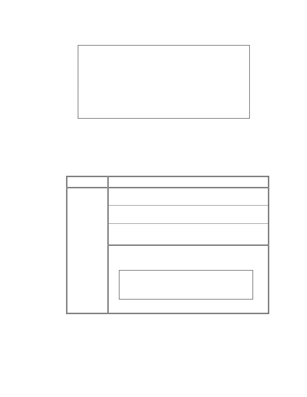
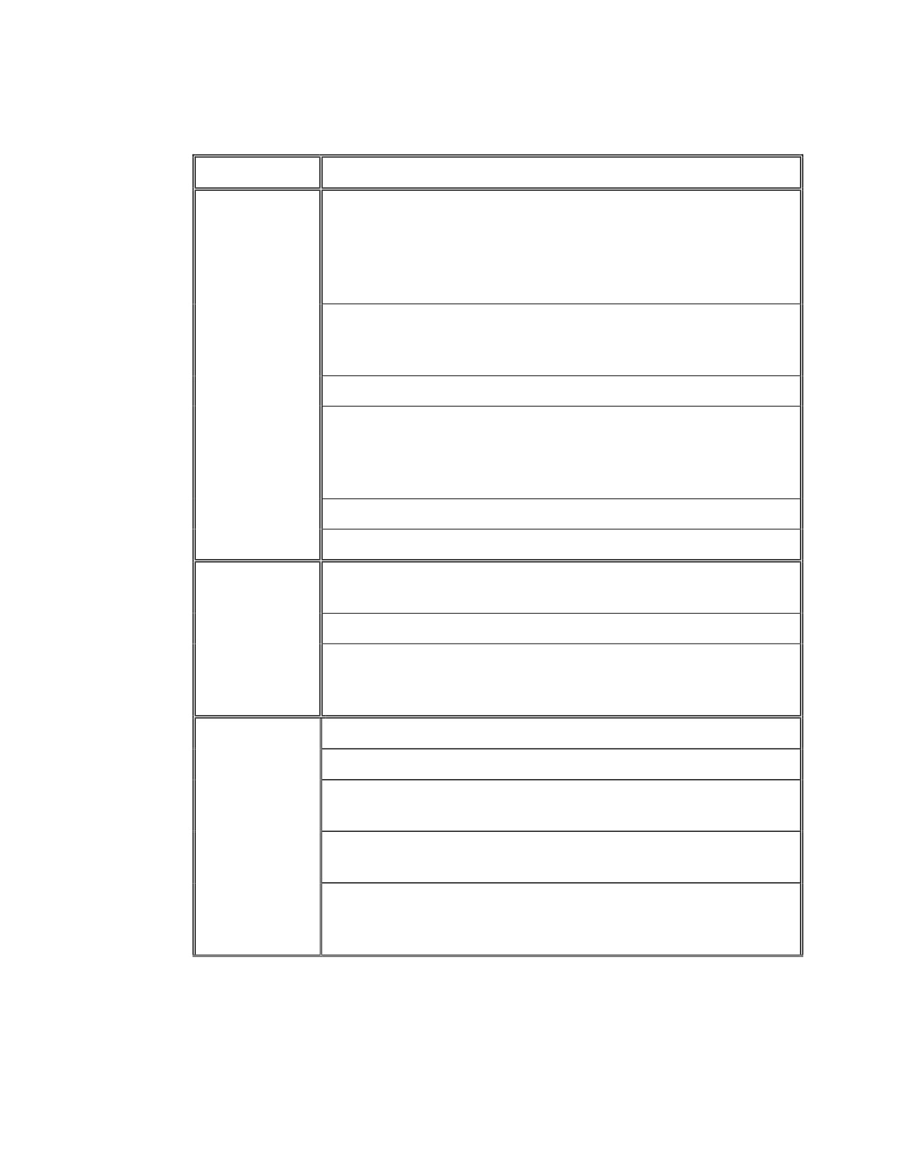
J.2
Maintenance and Inspection Schedule
Maintenance requirements and the corresponding schedule will vary with the
application and service conditions. The following maintenance and inspection
guidelines are recommended for turbines operated under normal conditions.
Frequency
Maintenance or Inspection Procedure
Daily
Check oil levels in bearing housings and governor. Add oil if
required.
Check for smoothness of operation, unusual noises, or other
changes in operating conditions.
Check overall appearance of turbine system for steam, oil, or
coolant leaks, and for external damage.
Check bearing oil temperatures and pressures; check coupling
temperature.
WARNING
DO NOT attempt TO MEASURE COUPLING
TEMPERATURE while the turbine is RUNNING.
Table J-1. Suggested Maintenance and Inspection Schedule
174
Maintenance, Maint. Sched. and Inspect. Sched.
Frequency
Maintenance or Inspection Procedure
Weekly
Test the over-speed trip system. Refer to Section E, Overspeed
Trip System, for the test procedure. This exercise will not only
confirm operation of the trip system, but will prevent sticking of
the over-speed trip valve and linkage due to corrosion or steam
deposits.
Check operation of auxiliary oil pump (on turbines with this
equipment). See oil system schematic diagram in Appendix for
location of test valve.
Check operation of all low air/oil pressure shut down device(s).
Drain small quantity of oil from system and conduct an oil
analysis. Determine the need for an oil change. If system is
equipped with and oil filter element, change the element at the
time of the oil change.
Check throttle valve and linkage for freedom of movement.
Lubricate the governor lever connection.
Monthly
Check bearing housings for sludge, sediment, or water
(condensate). Flush and refill, as required.
Check that oil rings rotate freely and smoothly.
Check throttle and overspeed trip linkage for looseness, wear,
and freedom of movement. Check governor drive coupling for
wear
Yearly
Change oil in the Woodward TG governor.
Remove and clean the steam strainer. Replace every three years.
Inspect internal components of the throttle valve for wear.
Replace, if required. Replace valve stem seals.
Clean and inspect the over-speed trip valve. Replace worn parts.
Replace valve stem seals.
Thoroughly inspect the throttle linkage and overspeed trip
linkage for wear. Check governor drive coupling for wear.
Replace as required.
Table J-1. Suggested Maintenance and Inspection Schedule (Cont.)
175
Maintenance, Maint. Sched. and Inspect. Sched
Inspect, clean, and flush bearing housings, oil reservoirs, and
Yearly
cooling water chambers.
Continued
Inspect carbon ring gland seals. Replace as required.
Check operation of the Sentinel warning valve.
Check alignment and foundation.
Remove top half of turbine casing and:
Clean scale and foreign material from wheels, buckets and
nozzles.
Check carbon rings for wear—remove, clean and reassemble
(refer to shaft packing section L.4.1 and L.4.2).
Check thrust bearing endplay.
Check calibration of all instrumentation.
Table J-1. Suggested Maintenance and Inspection Schedule (Cont.)
WARNING
Modification of, incorrect repair of, or use of non-DRESSER-
RAND repair parts on this turbine could result in a serious
malfunction or explosion that could result in serious injury or
death. Such actions will also invalidate ATEX Directive &
Machinery Directive Certifications for turbines that are in
compliance with those European Directives. Refer to Section M
-Replacement Parts/Factory Service
J.3
Major Inspection
Dresser-Rand recommends that the turbine be periodically shut down and
subjected to a major teardown and inspection. The frequency of this inspection will
depend on turbine service conditions, its maintenance history, the convenience of
scheduling a shutdown, the user’s experience with this or similar machines, or the
customer’s insurance company’s requirements..
J.4
Inspection Checklist
The following list summarizes parts that should be inspected during a major
inspection.
176

Maintenance, Maint. Sched. and Inspect. Sched.
Parts to be
Area to Be
Inspect for
Action Required
Inspected
Examined
Cracks, poor rivet
Consult manufacturer’s
Shrouds
heads
representative or factory.
File or grind smooth (Note:
Turbine and sector
removal of excessive material
blades
Corrosion, cracks,
Blades
will affect balance and blade
erosion
integrity. Consult manufacturer’s
rep. or factory if in doubt.)
Bearings
Surfaces
Wear, signs of
Replace if defective. Check
foreign matter,
condition of oil system.
scratches (pitting,
corrosion, galling,
excessive radial
play on ball
Drain oil & clean thoroughly.
bearings)
Fouling, scale,
Bearing Housings
Oil Reservoir
Refill with new oil.
rust, and water
Bearing housing
Labyrinth seal
Wear, dents in
Clean thoroughly.
oil seals
rings
surface, scale, dirt
Replace if badly worn or broken.
Breakage, wear,
Carbon rings
Clean. Carefully scrape high
high spots, dirt
spots.
Stainless steel
Glands
high velocity
Blistering, peeling
Replace shaft.
oxy fuel
Labyrinth
Wear, dents in
Clean thoroughly. Replace
steam seal
surface, scale, dirt
labyrinths if wear excessive.
teeth
Table J-2.
Inspection Checklist
177
Maintenance, Maint. Sched. and Inspect. Sched
Parts to be
Area to Be
Inspect for
Action Required
Inspected
Examined
Remove with solvent and/or
Stem
Scale
crocus cloth.
Galling, wear
Replace.
Replace valve or cage, as
Valve and cage
Cutting, scaling
required.
Throttle valve
Wear, excessive
Seal sleeves
clearance, steam
Replace.
leakage
Remove obstructions and dents.
Cracks, dents, or
Replace if cracked or broken.
Steam strainer
obstructions
Determine cause of damage and
correct.
Connecting rod
ends, linkage
Wear, excessive
Replace worn components. Clean
pins, bushings,
Governor linkage
clearance/play,
with solvent and polish, if
Governor drive
corrosion
necessary.
coupling
Scale and boiler
Remove with solvent and/or
Valve Spindle
compound, dirt
crocus cloth.
Valve Spindle
Wear, excessive
clearance, steam
Replace.
Overspeed trip
Spindle
leakage
valve
packing
Wear, cutting,
Valve seat
Replace.
cracks
Pilot valve
Wear
Replace.
Trip collar
Binding, scale,
Disassemble and clean; inspect
assembly
corrosion, wear
for wear; replace as an assembly.
Linkage,
Overspeed trip
Foreign material,
Clean and inspect. Replace worn
connecting rod
system
wear, corrosion,
and defective parts. Adjust and
ends, bushings,
freedom of
confirm correct operation before
pins, reset
movement
returning turbine to service.
handle
Table J-2. Inspection Checklist (Cont.)
178

Maintenance, Maint. Sched. and Inspect. Sched.
Parts to be
Area to Be
Inspect for
Action Required
Inspected
Examined
Corrosion,
Replace packing; remove foreign
Stem and
Hand Valves
foreign material,
material from stem; replace stem
packing
wear
if pitted or worn.
Piping
Fouling, scale,
Clean thoroughly to remove.
reservoir
rust, water,
Filter oil to remove dirt. Drain
flaking paint
oil; remove access covers to clean
out any accumulated scale and
refill with new oil.
Pressure lube
system (when used)
Oil filter(s)
Increased
Replace filter element
pressure drop
Oil cooler(s)
Fouling and
Clean according to
corrosion on both
manufacturer’s instructions
oil and water side
Table J-2. Inspection Checklist (Cont.)
Refer to the certified drawings and the appropriate vendor manual for inspection
and maintenance requirements for optional equipment.
J .4.1. Protective Devices and Steam Cleanliness
RAPID CLOSING OF VALVES SUPPLIED WITH THE TURBINE IS ESSENTIAL
TO PROTECT AGAINST OVERSPEED AND POSSIBLE OTHER MECHANICAL
PROBLEMS. Such valves (governor valves, trip valves, trip throttle valves, etc.) must
close in fractions of a second; and deposits on valves, seats, stems, etc cannot impede
their movement. Deposits can form rapidly - as a result of improper water treatment
and/or entrainment of impurities in the steam supply.
The design clearance at the end of the governor controlled steam valve(s) and trip or trip
and throttle valve stems are required to minimize steam leakage from the turbine.
The stem clearances used by Dresser-Rand are based on many years of practical
experience and will prevent binding under normal temperatures and steam cleanliness.
HOWEVER, THE DEGREE OF STEAM CLEANLINESS TOLERANCE ON
179
Maintenance, Maint. Sched. and Inspect. Sched
CONTROL VALVE AND TRIP VALVE COMPONENTS IS LIMITED AND
DEPOSITS MUST BE PREVENTED.
Steam cleanliness at the turbine flange is essential to reliable turbine operation.
Control of steam cleanliness is the responsibility of the turbine user and his system
operator. Cooperation with boiler manufacturers and water treatment specialists is
strongly recommended to maintain steam purity and cleanliness. Boiler operation must
prevent boiler compounds from being carried over to the steam turbine and causing
deposits on the valves.
DRESSER-RAND RECOMMENDS THAT THE TURBINE USER PERFORM
CAREFUL AND FREQUENT INSPECTION OF TRIP SYSTEM TO ASSURE NO
DEPOSIT BUILD-UP OCCURS that could cause the safety devices and valves to
become inoperative.
WE RECOMMEND THAT FREQUENT EXERCISING OF
(I.E. LIMITED
MOVEMENT/PARTIAL STROKING) THE CONTROL COMPONENTS BE
PERFORMED, especially if boiler carryover deposits may have occurred.
Exercising of the governor controlled valves may be performed by either a small load
change (where practical) or steam inlet pressure change. This can be accomplished by
choking the trip or trip and throttle valve. At the same time, the trip or trip and throttle
valve is exercised.
CAUTION: If the KW load on a turbine-generator cannot be reduced in the normal
manner, it indicates the possibility of unacceptable deposits on the control valve
components. STUCK CONTROL VALVES ARE A DANGER SIGNAL THAT THE
TRIP VALVE MAY ALSO BE STUCK.
UNDER THESE CONDITIONS IT IS IMPERATIVE THAT THE GENERATOR LOAD
NOT BE REMOVED UNTIL THE TRIP VALVE IS CLOSED. If the trip valve cannot be
closed by normal means, then other valves in the steam system must be used to cut off the steam
supply to the turbine. THE UNIT CIRCUIT BREAKER SHOULD NEVER BE OPENED
WHILE LOAD IS ON THE UNIT AND TRIP AND THROTTLE / GOVERNOR
VALVES ARE INOPERABLE. FAILURE TO FOLLOW THESE PRECAUTIONS
COULD CAUSE A SEVERE OVERSPEED WITH EXTREME DANGER TO THE
TURBINE AND OPERATING PERSONNEL.
J.5
Factory Service
Dresser-Rand maintains repair and rebuild facilities worldwide. In addition,
factory-trained servicemen are available for start-up, field service, and
troubleshooting. Consult your Dresser-Rand manufacturer’s representative or the
factory for service needs. Refer to Section M, Replacement Parts/Factory Service.
180
Maintenance, Maint. Sched. and Inspect. Sched.
J.6
Factory Replacement Parts
WARNING
Modification of, incorrect repair of, or use of non-DRESSER-
RAND repair parts on this turbine could result in a serious
malfunction or explosion that could result in serious injury or
death. Such actions will also invalidate ATEX Directive &
Machinery Directive Certifications for turbines that are in
compliance with those European Directives. Refer to Section M
-Replacement Parts/Factory Service
Dresser-Rand recommends that only Dresser-Rand-supplied parts be used in
Dresser-Rand turbines. The use of Dresser-Rand parts ensures that replacement
components are manufactured from the highest quality materials, to exacting
tolerances and specifications, thereby assuring efficient, long-lasting, and
maintenance-free operation, under service conditions that the turbine was built for.
Dresser-Rand and selected Dresser-Rand manufacturer’s representatives maintain
a supply of the most frequently requested spare parts for immediate shipment
worldwide. Parts requested less frequently can be manufactured quickly on an
emergency basis when required.
Your Dresser-Rand manufacturer’s representative can supply you with an
interchangeability list and a suggested stocking list of recommended spare parts for
your turbine or turbines, allowing you to stock spare parts at your facility. Refer to
Section M, Replacement Parts/Factory Service.
181
Troubleshooting
THIS PAGE WAS LEFT BLANK
INTENTIONALLY
182
Troubleshooting
Section K
Troubleshooting
K.1
Introduction
This section should be consulted when the turbine is not operating satisfactorily.
The table in Section K.2 lists the more common symptoms, probable causes, and
corrective actions in each case. If the problem cannot be completely remedied
using the table, refer all questions to your local Dresser-Rand manufacturer’s
representative, or to:
Dresser-Rand Company
Wellsville Operations, P.O. Box 592
Steam Turbine Business Unit
Wellsville, NY 14895-0592
800-828-2818
585-596-3100
If corrective actions specified in items 5 through 8 of Section K.2 are attempted
and are not successful, and if the factory must be consulted, it is imperative to
provide exhaust pressure, speed, horsepower, and chest pressure. Chest pressure is
measured by installing a pressure gage in a hand-valve chamber drain hole and
reading the pressure with the hand-valve closed.
K.2
Troubleshooting
The following table lists common problems, possible causes, and the appropriate
corrective action of turbines that have operated successfully and develop problems
during the course of normal operation. Problems encountered during initial start-
up should be referred to the above contact information.
183