Carrier 30AWH004HB / 30AWH006HB / 30AWH008HB / 30AWH012HB. Service Manual - page 8
 

  Главная      Manuals     Carrier 30AWH004HB / 30AWH006HB / 30AWH008HB / 30AWH012HB. Service Manual (2010)


Search            copyright infringement  


Content      ..     6      7      8      9     ..


Carrier 30AWH004HB / 30AWH006HB / 30AWH008HB / 30AWH012HB. Service Manual - page 8


113

30AW

Exchange
parts
name

Work procedure (IMPORTANT: Ensure gloves are 
worn at all times to avoid risk of injury)

Remarks

(7)

Reactors 
(012)

1. Perform the works from 1 to 4 of (1) and (2).
2. Remove the inverter assembly item (4).
3. Remove the reactors’ connectors. 

5BLFPòUIFTDSFXT 451tQDTöYJOH

the reactor to the partition plate.

5. Pull the reactor upward and detach it from the 

partition plate. 

6. Replace the fail reactor with a new one.

(8)

Control 
P.C. Board
(015)

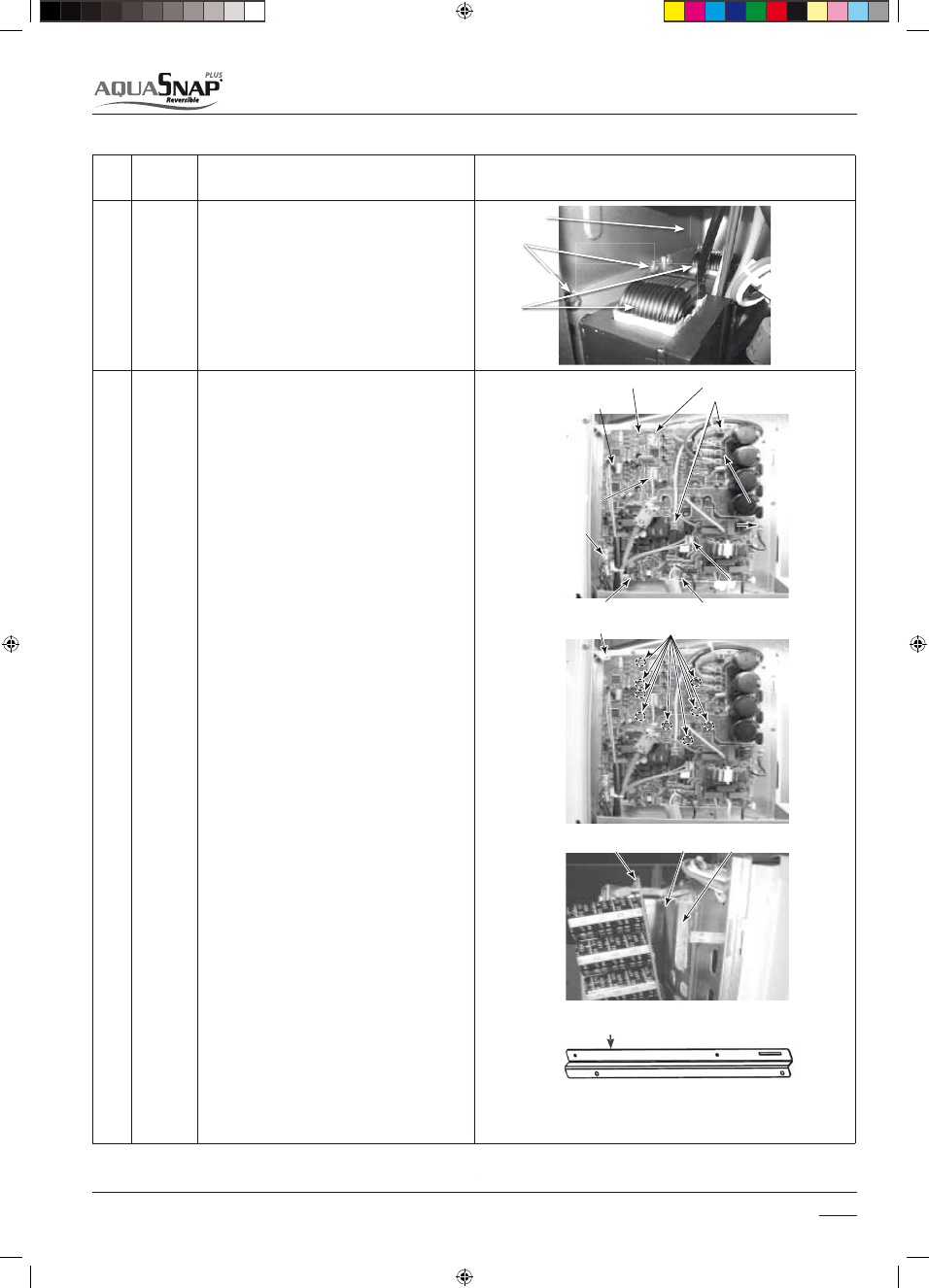
1. Perform the works from 1 to 4 of (1) and (2). 

WARNING

Never disassemble the inverter for 1 minute after po-

XFSTVQQMZIBTCFFOUVSOFEPòCFDBVTFBOFMFDUSJD

shock may be caused.

2. Remove the connectors connected to the control 

P.C. board. (Indoor power supply, Temperature 

sensor, PMV coil, 4-way valve coil, Compressor case
thermo, Fan motor)

t6OMPDLUIFMPDLPGUIFIPVTJOHQBSUBOEUIFO

remove the connectors.

3. Remove the lead wires connected to the control P.C

board.
Compressor lead U: CN200 Red
V: CN201 White
W: CN202 Black
Reactor cord CN05 White CN06 White

4. Remove the earth wire from the control P.C. board. 

(Trust B tight screw Ø4 × 6, 1 pc.)

5.  Remove the fixing screws of the control P.C. board. 

(Screw with collar for fixing element Ø3 × 16, 9 pcs. 
Pan S tight screw for fixing board Ø3 × 20, 1 pc.)

6.  Remove the control P.C. board. (Supporter: 5 

positions)

NOTE :

Be careful to take out because there is sealing 
material for the heat sink.

7. Replace the control P.C. board with a new one.

NOTE :

t#FTVSFOPUUPDPOGVTFGPS$PNQSFTTPSMFBE7

(CN201 White), Reactor lead CN05 and CN06.

t#FTVSFOPUUPDPNFPòPGUIFJOTVMBUJOHTIFFU

Attention:

 The inverter board is fixed at the side ca-

binet by a steel braket. When replace the P.C. Board 
remember to detach it from the defective board and 
to screw it at the new one.

Control P.C. board

Upper fan motor

Compressor lead

Ear th wire

wer

an motor

emperature

sensor

Compressor lead

Earth wire

Lower 
fan motor

Temperature 
sensor

4-way valve coil

4-way valve coil

PMV coil

Indoor power supply

P.C. board 
fixing screw

Insulating sheet

Control P.C. board

Sealing material

Element fixing screws 
(9 positions)

Compressor

case thermo.

Reactor lead


    Maintenance

8

Screws

Reactors

Partition plate

Steel braket

14-03-2011   14:46:49

114

30AW

Exchange
parts
name

Work procedure (IMPORTANT: Ensure gloves are 
worn at all times to avoid risk of injury)

Remarks

(9)

Reactor 
(015)

1. Perform the works from 1 to 4 of (1) and (2).
2. Remove the reactor lead connected to the control 

P.C. board. CN05 White, CN06 White

3. Cut the bundling band which bundled the compres-

sor lead and fan motor lead.

4. Remove the reactor. (Trust B tight screw, Ø4 × 6, 2 

pcs.)

5. Replace the reactor with a new one.

NOTE :

Be sure to bundle the removed bundling band with 
the bundling band on the market.
Be careful so that the fan motor lead does not come 
to contact with the reactor body.

Bundling band

(Compressor lead, Reactor lead)

Bundling band
(Compressor lead, Reactor lead)

Control P.C. board

Reactor lead

Reactor lead

Reactor body

Bundling band
(Fan motor lead, Reactor lead)

Fan motor lead

(10)

GMC
Board
assembly

1. Perform the works from 1 to 4 of (1).

5BLFPòUIFTDSFXT 455Y-QDTöYJOHUIF

GMC cover and remove it gain access to inspect the 
board.

3. Disconnect lead wires and connectors connected 

from the GMC board assembly to other parts. 

J6A Water Enter Exchanger Sensor J6B TR Sensor
J6C Water Exit Exchanger Sensor
J22 Outdoor Air Sensor
J18 Mode (Heat/Cool)
J5 Remote Control
J20 Eco / Antifreeze Switch
J8 Communications Receive
J16 ON/OFF and Power limitation Switch
J20 Sanitary Water Dry contact
J4 Water Exchanger and 3 way valve
J7 Water pump Speed – Defrost and TFC status
– EHS and Dehumidifier
J11 Alarm status and Defrost signal

REQUIREMENT

As each connector has a lock mechanism, avoid to 

remove the connector by holding the lead wire, but 
by holding the connector.

4. Pull the GMC assembly upward and detach it from 

the partition plate. The GMC board is attach to the 
partition plate by two hooks.

5. Remove 4 hooking claws of GMC board base and 

pull the GMC board upward.

6. Replace the fail GMC board with a new one.

Caution: 

When mounting a new board, check that the 

board is correctly set in the groove of the base holder 
of GMC board base.

7. Attach the removed connectors at the GMC board 

BOEBUUBDIUIFUBLFOPòTDSFXTUPUIFPSJHJOBM

positions.


    Maintenance

8

Hooks

GMC cover

GMC board

14-03-2011   14:46:51

115

30AW

Exchange
parts
name

Work procedure (IMPORTANT: Ensure gloves are 
worn at all times to avoid risk of injury)

Remarks

(11)

Fan motor

1 Perform the works from 1 to 4 of (1) and (3).

5BLFPòUIFøBOHFOVUöYJOHUIFGBONPUPSBOEUIF

propeller. Lose the flange nut by turning clockwise. 
(To tighten the flange nut, turn counter-clockwise.)

3. Remove the propeller fan.
4. Disconnect the connector for fan motor from the 

inverter.

5BLFPòUIFöYJOHTDSFXT QDTIPMEJOHCZIBOET

so that the fan motor does not fall.

6. Replace the fail fan motor with a new one. 

Caution:
The same propeller fan and the fan motor are used 
at upper and lower sides.
Be sure that the propeller fan does not come to 
contact with the fan motor lead.

(12)

Compres-
sor

Perform the works from 1 to 4 of (1) and (2), (3), (4), 

(7), (8).

1. Discharge refrigerant gas.

3FNPWFUIFQJQJOHQBOFMUBLFPòUIFöYJOHTDSFXT

 451tQDT

3FNPWFUIFQBSUJUJPOQMBUFUBLFPòTDSFXTGSPNUIF

CBTFQMBUF 451tQDTBOEGSPNUIF
IFBUFYDIBOHFS 451tQDT3FNPWF

also the nut fixing the liquid receiver and the parti-
tion plate.

4. Remove the noise-insulator.
5. Remove the terminal covers of the compressor, and 

disconnect lead wires of the compressor and the 
compressor thermo assembly from the terminal.

6. Remove pipes connected to the compressor with a 

burner.

CAUTION

Ensure flames of burner do not damage 4-way valve 
or PMV. (If doing so, a malfunction may be caused.)

5BLFPòUIFöYJOHTDSFXTPGUIFCPUUPNQMBUFBOE

IFBUFYDIBOHFS 451tQDT

8. Pull upward the refrigerating cycle.

5BLFPòOVUöYJOHUIFDPNQSFTTPSUPUIFCPUUPN

place.

CAUTION

When reconnecting the lead wires to the compressor 
terminals after replacement of the compressor, be 
sure to caulk the Faston terminal without loosening.

10. Draw out the compressor toward you


    Maintenance

8

Flange nut

Propeller

Piping panel

Terminal cover

Nuts

Lead wires

Check joint

Noise insulator

Screws

N

N

14-03-2011   14:46:52

116

30AW

Exchange
parts
name

Work procedure (IMPORTANT: Ensure gloves are 
worn at all times to avoid risk of injury)

Remarks

(13)

Liquid
receiver

1. Perform the works from 1 to 4 of (1) and (2),

(3), (4), (5), (8).

2. Discharge refrigerant gas.
3. Remove the nut fixing the liquid receiver and

the partition plate.

3FNPWFUIFQBSUJUJPOQMBUFUBLFPòTDSFXTGSPNUIF

CBTFQMBUF 451tQDTBOEGSPNUIF
IFBUFYDIBOHFS 451tQDT

5. Remove pipes connected to the liquid receiver

with a burner.

CAUTION

Ensure flames of burner do not damage other
components. (If doing so, a malfunction may be
caused.)

Pulse
modula-
ting
valve 
(PMV)
coil

t%FUBDINFOU

1. Perform the works from 1 to 4 of (1) and (2).

2. Hold outside of the coil by hands and turn it while 

lifting upward.

5IFöYJOHIPPLTDPNFPòUIFöYJOHDPODBWJUJFTBOE

then the coil can be removed from PMV body.

t"UUBDINFOU

4. Match the positioning extrusion of the coil surely to 

the concave part of PMV body, and then fix it.

(14)

Fan guard

t%FUBDINFOU

1. Perform works from 1 to 4 of (1) and (3).
2. Remove the front cabinet, and put it down so that 

fan guard side directs downward.

Caution: Perform works on a corrugated cardboard, 

cloth, etc. to prevent flaw on the product.

3. Remove the screws fixing the bell-mouth (ST8P Ø8.2 

tQDT

4. Remove the bell-mouth.
5. Remove the screws fixing the fan guard (ST8P Ø8.2 

tQDT

6. Remove hanging hook of the fan guard by pushing 

with a minus screwdriver.

t"UUBDINFOU

7. Fix the hanging hooks by pushing with hands.

REQUIREMENT

Check that all the hanging hooks are fixed to the 
specified positions.

"GUFSBUUBDINFOUöYJUXJUITDSFXT 451t

2 pcs).

9. Mount the bell-mouth coupling on metal lip of air-

outlet cabinet.

"GUFSBUUBDINFOUöYJUXJUITDSFXT 451t

2 pcs).


    Maintenance

8

Liquid receiver

Nut

Partition plate

PMV body

PMV coil

Bell-mouth

Hanging Hooks

Screw

Screw

te

14-03-2011   14:46:55

117

30AW


    Maintenance

8

Remarks

Work procedure (IMPORTANT: Ensure gloves are 
worn at all times to avoid risk of injury)

Remarks

(15)

Water 
circuit

CAUTION

:

To replace a water circuit part, first close the water 
supply source valve and the valve of water pipe 
connected to the unit.

(16)

Expansion 
vessel 
(Only H 
versions)

1. Perform works from 1 to 4 of (1), (2).
2. Remove the expansion vessel connection (flare nut).
3. Replace the packing to new one when installing the 

expansion vessel.

IMPORTANT

:

After the expansion vessel replacement repair,
open the water supply source valve and water
piping valve to pass water through the hydro unit, 
and check that the expansion vessel connection has 
no water leakage.

(17)

Relief 
valve

1. Perform works from 1 to 4 of (1).
2. Remove the piping panel
3. Remove the relief valve.

CAUTION:

The relief valve connection uses an O ring for water 

TFBM#FDBSFGVMOPUUPTDSBUDIUIF0SJOHPUIFSXJTF

water leakage may occur.

IMPORTANT

:

After the relief valve replacement repair, open the 
water supply source valve and water piping valve to 
pass water through the hydro unit, and check that 
the relief valve connection has no water leakage.

(18)

Automatic 
purge 
valve

1. Perform works from 1 to 4 of (1) and (2).
2. Remove the automatic purge valve.

IMPORTANT

After the automatic purge valve replacement repair, 
open the water supply source valve and water 
piping valve to pass water through the hydro unit, 
and check that the air vent valve connection has no 
water leakage.

Automatic purge 
valve

Flow switch

Expansion vessel

Entering
water

Exiting water

Water drain

Expansion
vessel

Automatic 
purge valve

Relief valve

Automatic purge 
valve

Nut

Inlet water

Water Pump

Relief valve

BPHE

v

I

mp

Relie

e

BPH

ge

14-03-2011   14:46:58

118

30AW

Remarks

Work procedure (IMPORTANT: Ensure gloves are 
worn at all times to avoid risk of injury)

Remarks

(19)

Flow 
switch 

1. Perform works from 1 to 4 of (1) and (2).
2. Remove the relative connector
3. Remove the flow switch.

CAUTION:

The flow switch connection uses an O ring for water 

TFBM#FDBSFGVMOPUUPTDSBUDIUIF0SJOHPUIFSXJTF

water leakage may occur.
Place a flow sensor parallel to the water heat 
exchanger inlet pipe so that the wire is place on the 
right side from the front view.

(20)

Water 
heat
exchanger 
(BPHE)

1. Perform works from 1 to 4 of (1) and (2).
2. Disconnect all the power source cable, unit connec-

tion cable, and cylinder connection cable.

3. Discharge refrigerant gas.

5BLFPòUIFOVUDPOOFDUJOHUIFIFBUFYDIBOHFSUP

the water circuit

5. Remove refrigerant pipes connected to the com-

pressor with a burner.
CAUTION
Ensure flames of burner do not damage PMV. (If 
doing so, a malfunction may be caused.)

5BLFPòUIFOVUTöYJOHUIFXBUFSIFBUFYDIBOHFSUP

the heat exchanger cover.

5BLFPòUIFTDSFXTöYJOHUIFIFBUFYDIBOHFSDPWFS

UPUIFCBTFQMBUF 451tQDTBOEUIF
JOMFUXBUFSQJQF 451tQDT

IMPORTANT:
After the water heat exchanger replacement repair, 
open the water supply source valve and water 
piping source valve to pass water through the hydro 
unit, and check that the connection has no water 
leakage.
After connecting the refrigerant pipe, check that the 
connection has no refrigerant leakage.

(21)

TWI sensor
TWO 
sensor

1. Perform works from 1 to 4 of (1) and (2).
2. Take the sensors out.

(22)

Pump
(Only H 
versions)

1. Perform works from 1 to 4 of (1) and (2).
2. Remove the relative connectors
3. Remove the 2 nuts of the heater connection and the 

lower side of the pump.

4. Remove the pump pulling it out.

CAUTION:
The pump connection uses a liquid packing for
water seal. When replacing the pump, use a
packing which was slathered with the liquid gasket.

IMPORTANT:
After the pump replacement repair, open the water 
supply source valve and water piping valve to pass 
water through the hydro unit, and check that the 
pump connection has no water leakage.

Flow switch

BPHE

Heat exchanger cover

Water pump motor

Water pump

Nuts

Nuts

14-03-2011   14:46:59

119

30AW

Unit

Frequency

Periodic inspection details

Insulation measurement (Power source circuit/ 
Compressor)

Annually

Insulation measurement with a mega tester

Operation check 

Annually

Hot water supply/ Heating/ Cooling operation 
check with remote controller.

Refrigerant leakage/ Water leakage inspection. 

Annually

Visual inspection and check with a leak tester: No 
leakage must be found.

Water heat exchanger inspection (Internal dirt 
and clogging)

Annually

Checking for water dirtiness in a closed cycle, 
Cleaning.

Inlet / Outlet water temperature measurement 

Annually

Temperature measurement: Temperature measu-
rement during an operation.

Circulation pump inspection 

Annually

No leakage or abnormal noise must be found 
(Replacement every 10 years: Charged).

Automatic air purge valve inspection 

Annually

Water leakage, Air vent.

Expansion vessel 

Annually

Visual check for charge pressure abnormality, 
water leakage, or corrosion.

Heater assembly

Annually

Check for appearance damage, deformation, or 
loose terminal.

Flow switch 

Annually

Operation check while running

Safety valve 

Annually

Water leakage, Appearance check, Drainage 
check.

Power source measurement (No-load voltage/ 
Rated operation) 

Annually

Electronic voltage measurement: 230V ±23V

Operation frequency (Unit operation check) 

Annually

Frequency check by rated operation 

Air heat exchanger inspection (Dirt and clogging) 

Annually

Visual inspection, Clear clogging

Fan inspection (Scratch, damage) 

Annually

Check  for scratches or damages to the fan or 
abnormal motor sound

Cycle parts (Compressor, 4-way valve, Pulse motor 
valve)

Annually

Operation check by trial run

Inverter control board, GMC board, Terminal block  Annually

Check for loose connector and connecting 
terminal

8.4 Periodic Inspection Items

14-03-2011   14:47:00

120

30AW


    Spare 

Parts

9

For the spare parts refer to specific document.

14-03-2011   14:47:00

121

30AW


  Extended 

rating

10

10 Extended rating

Size 004 Heating

COP 30-35 

°C

1.50

2.50

3.50

4.50

5.50

6.50

7.50

-25

-15

-5

5

15

25

35

OA

T

 [°

C

]

Max

Med

Mi

n

F

re

q

ue

nc

y

CA

PA

CITY [

k

W

30-

3

C

0.00

1.00

2.00

3.00

4.00

5.00

6.00

7.00

8.00

9.00

10.00

11.00

12.00

-25

-15

-5

5

15

25

35

Max

Med

Mi

n

O

A

T [°

C

]

F

re

q

ue

nc

y

COP 40

-45 

°C

1.50

2.50

3.50

4.50

5.50

6.50

7.50

-25

-15

-5

5

1

5

2

5

3

5

OA

T

 [

°C]

Max

Med

Mi

n

F

re

q

ue

nc

y

CA

PA

CITY [

k

W

40-

4

C

0.00

1.00

2.00

3.00

4.00

5.00

6.00

7.00

8.00

9.00

10.00

11.00

12.00

-25

-15

-5

5

1

5

2

5

3

5

Max

Med

Mi

n

O

A

T [°

C

]

F

re

q

ue

nc

y

14-03-2011   14:47:02

122

30AW


  Extended 

rating

10

COP 50

-55 

°C

1.50

2.00

2.50

3.00

3.50

4.00

4.50

5.00

-25

-15

-5

5

1

5

2

5

3

5

OA

T

 [

°C]

Max

Med

Mi

n

F

re

q

ue

nc

y

CA

PA

CITY [

k

W

50-

5

C

0.00

1.00

2.00

3.00

4.00

5.00

6.00

7.00

8.00

9.00

10.00

11.00

12.00

-25

-15

-5

5

15

25

35

Max

Med

Mi

n

O

A

T [°

C

]

F

re

q

ue

nc

y

COP 55

-6

°C

1.50

2.00

2.50

3.00

3.50

4.00

4.50

5.00

-25

-15

-5

5

15

25

35

OA

T

 [

°C]

Max

Med

Mi

n

F

re

q

ue

nc

y

CA

PA

CITY [

k

W

55-

6

C

0.00

1.00

2.00

3.00

4.00

5.00

6.00

7.00

8.00

9.00

10.00

11.00

12.00

-25

-15

-5

5

1

5

2

5

3

5

Max

Med

Mi

n

O

A

T [°

C

]

F

re

q

ue

nc

y

14-03-2011   14:47:03

123

30AW


  Extended 

rating

10

Size 004 Cooling

COP 12

-7

 °

C

0.00

2.00

4.00

6.00

8.00

10.00

12.00

14.00

0

5

10

15

20

25

30

35

40

45

50

OA

T

 [

°C]

Max

Med

Mi

n

F

re

q

ue

nc

y

CA

PA

CITY 

[k

W

] 12-

7

 °

C

0.00

1.00

2.00

3.00

4.00

5.00

6.00

7.00

8.00

0

5

10

15

20

25

30

35

40

45

50

OA

T

 [

°C]

Max

Med

Mi

n

F

re

q

ue

nc

y

CA

PA

CITY 

[k

W

] 23-

1

8 °

C

0.00

1.00

2.00

3.00

4.00

5.00

6.00

7.00

8.00

9.00

10.00

11.00

12.00

0

5

10

15

20

25

30

35

40

45

50

OA

T

 [°

C

]

Max

Med

Mi

n

F

re

q

ue

nc

y

COP 23

-1

°C

0.00

2.00

4.00

6.00

8.00

10.00

12.00

14.00

16.00

18.00

20.00

22.00

24.00

0

5

10

15

20

25

30

35

40

45

50

OA

T

 [°

C

]

Max

Med

Mi

n

Frequenc

y

14-03-2011   14:47:05

124

30AW

Size 006 Heating

C

O

P

 30-35 

°C

1.50

2.50

3.50

4.50

5.50

6.50

7.50

-25

-15

-5

5

1

5

2

5

3

5

OA

T

 [

°C]

Max

Med

Mi

n

F

re

q

ue

nc

y

C

A

P

A

C

IT

Y

 [

k

W] 

30-35 °

C

0.00

1.00

2.00

3.00

4.00

5.00

6.00

7.00

8.00

9.00

10.00

11.00

12.00

-25

-15

-5

5

15

25

35

OA

T

 [

°C]

Max

Med

Mi

n

F

re

q

ue

nc

y

CO

P 40-45 

°C

1.50

2.50

3.50

4.50

5.50

6.50

7.50

-25

-15

-5

5

1

5

2

5

3

5

OA

T

 [

°C]

Max

Med

Mi

n

F

re

q

ue

nc

y

C

A

P

A

C

IT

Y

 [

k

W] 

40-45 °

C

0.00

1.00

2.00

3.00

4.00

5.00

6.00

7.00

8.00

9.00

10.00

11.00

12.00

-25

-15

-5

5

15

25

35

OA

T

 [

°C]

Max

Med

Mi

n

F

re

q

ue

nc

y

14-03-2011   14:47:06

125

30AW

CO

P 50-55 

°C

1.50

2.00

2.50

3.00

3.50

4.00

4.50

5.00

-25

-15

-5

5

1

5

2

5

3

5

OA

T

 [

°C]

Max

Med

Mi

n

F

re

q

ue

nc

y

C

A

P

A

C

IT

Y

 [

k

W] 

50-55 °

C

0.00

1.00

2.00

3.00

4.00

5.00

6.00

7.00

8.00

9.00

10.00

11.00

12.00

-25

-15

-5

5

15

25

35

OA

T

 [

°C]

Max

Med

Mi

n

F

re

q

ue

nc

y

C

A

P

A

C

IT

Y

 [

k

W] 

55-60 °

C

0.00

1.00

2.00

3.00

4.00

5.00

6.00

7.00

8.00

9.00

10.00

11.00

12.00

-25

-15

-5

5

15

25

35

OA

T

 [

°C]

Max

Med

Mi

n

F

re

q

ue

nc

y

CO

P 55-60 

°C

1.50

2.00

2.50

3.00

3.50

4.00

4.50

5.00

-25

-15

-5

5

1

5

2

5

3

5

O

A

T [°

C

]

Max

Med

Mi

n

F

re

q

ue

nc

y

14-03-2011   14:47:08

126

30AW

Size 006 Cooling

COP 12-7 °

C

0.00

2.00

4.00

6.00

8.00

10.00

12.00

14.00

0

5

10

15

20

25

30

35

40

45

50

OA

T

 [°

C

]

Max

Med

Mi

n

F

re

q

ue

nc

y

CA

PA

CIT

Y

 12-7 °

C

0.00

1.00

2.00

3.00

4.00

5.00

6.00

7.00

8.00

0

5

10

15

20

25

30

35

40

45

50

OA

T

 [°

C

]

Max

Med

Mi

n

F

re

q

ue

nc

y

COP 23-18 

°C

-1.0

0

1.

00

3.

00

5.

00

7.

00

9.

00

11.

0

0

13.

0

0

15.

0

0

17.

0

0

19.

0

0

21.

0

0

23.

0

0

25.

0

0

0

5

10

15

20

25

30

35

40

45

50

OA

T

 [°

C

]

Ma

x

Me

d

Mi

n

F

re

q

ue

nc

y

CA

PA

CIT

Y

 12-7 °

C

0.

00

2.

00

4.

00

6.

00

8.

00

10.

0

0

12.

0

0

0

5

10

15

20

25

30

35

40

45

50

OA

T

 [°

C

]

Ma

x

Me

d

Mi

n

F

re

q

ue

nc

y

14-03-2011   14:47:09

127

30AW

Size 008 Heating

COP 30-35 °

C

1.50

2.50

3.50

4.50

5.50

6.50

7.50

-25

-15

-5

5

15

25

35

OA

T

 [

°C]

Max

Med

Mi

n

F

re

q

ue

nc

y

CA

PA

CIT

Y

 [kW] 30-35 °

C

0.00

1.00

2.00

3.00

4.00

5.00

6.00

7.00

8.00

9.00

10.00

11.00

12.00

-25

-15

-5

5

15

25

35

OA

T

 [

°C]

Max

Med

Mi

n

F

re

q

ue

nc

y

CA

PA

CIT

Y

 [kW] 40-45 °

C

0.00

1.00

2.00

3.00

4.00

5.00

6.00

7.00

8.00

9.00

10.00

11.00

12.00

-25

-15

-5

5

15

25

35

OA

T

 [

°C]

Max

Med

Mi

n

F

re

q

ue

nc

y

COP 40-45 

°C

1.50

2.50

3.50

4.50

5.50

6.50

7.50

-25

-15

-5

5

1

5

2

5

3

5

OA

T

 [

°C]

Max

Med

Mi

n

F

re

q

ue

nc

y

14-03-2011   14:47:11

128

30AW

CA

PA

CIT

Y

 [kW] 50-55 °

C

0.00

1.00

2.00

3.00

4.00

5.00

6.00

7.00

8.00

9.00

10.00

11.00

12.00

-25

-15

-5

5

15

25

35

OA

T

 [

°C]

Max

Med

Mi

n

F

re

q

ue

nc

y

COP 50-55 

°C

1.50

2.00

2.50

3.00

3.50

4.00

4.50

5.00

-25

-15

-5

5

1

5

2

5

3

5

OA

T

 [

°C]

Max

Med

Mi

n

F

re

q

ue

nc

y

CA

PA

CIT

Y

 [kW] 55-60 °

C

0.00

1.00

2.00

3.00

4.00

5.00

6.00

7.00

8.00

9.00

10.00

11.00

12.00

-25

-15

-5

5

15

25

35

OA

T

 [

°C]

Max

Med

Mi

n

F

re

q

ue

nc

y

COP 55-60 

°C

1.50

2.00

2.50

3.00

3.50

4.00

4.50

5.00

-25

-15

-5

5

1

5

2

5

3

5

OA

T

 [

°C]

Max

Med

Mi

n

F

re

q

ue

nc

y

14-03-2011   14:47:12


Content      ..     6      7      8      9     ..