Takeuchi Hydraulic Excavator TB175 (No. 17512105~). Operator's Manual (2007) - page 10
 

  Index      Manuals     Takeuchi Hydraulic Excavator TB175 (No. 17512105~). Operator's Manual (2007)


Search            copyright infringement  


Content      ..     8      9      10      11     ..


Takeuchi Hydraulic Excavator TB175 (No. 17512105~). Operator's Manual (2007) - page 10


144

TROUBLESHOOTING

If the Battery Goes Dead

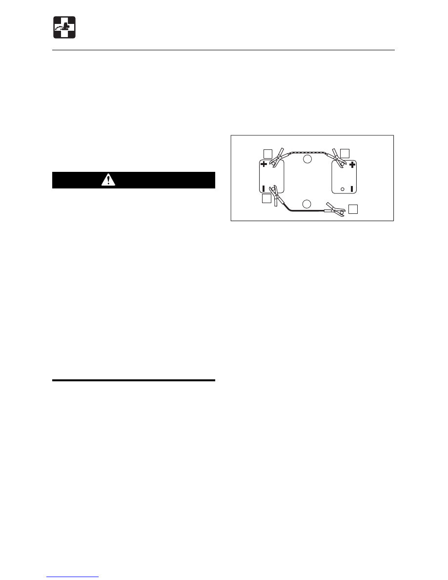
Connecting the jumper cables

IMPORTANT: Set the starter keys of both
the rescue vehicle and problem vehicle
to the OFF position.

1. Connect the clip of jumper cable (R) to

the problem vehicle’s “+” terminal.

2. Connect the other clip of jumper cable (R)

to the rescue vehicle’s “+” terminal.

3. Connect the clip of jumper cable (B) to

the rescue vehicle’s “–” terminal.

4. Connect the other clip of jumper cable (B)

to the problem vehicle’s engine block.
Connect the clip as far from the battery as
possible.

Starting the engine
1. Check that the clips are securely

connected to the terminals.

2. Start the rescue vehicle’s engine and run

it at high speed.

3. Start the problem vehicle’s engine.

The following symptoms indicate that the
battery is dead:

¡

The starter motor does not turn or turns
weakly, and the engine does not start.

¡

The horn is weak.

Procedure
Use jumper cables and start the engine using
the rescue vehicle’s battery.

 WARNING

¡

¡

¡

¡

¡

Use jumper cables only in the
recommended manner. Improper use
of jumper cables can result in battery
explosion or unexpected machine
motion.
• Do not let the problem vehicle and

rescue vehicle touch each other.

• Do not let the “+” and “–” clips of the

jumper cables touch each other.

• Connect the jumper cables to the “+”

terminals first, and disconnect them
from the “–” terminals (ground) first.

• Connect the final clip of the jumper

cable to a point as far away from the
battery as possible.

¡

¡

¡

¡

¡

Use safety glasses when using jumper
cables to start the machine.

IMPORTANT: Use jumper cables and
clips of a size suited to the battery’s
capacity.  Do not used damaged or
corroded jumper cables and clips.
IMPORTANT: The rescue vehicle’s
battery must have the same capacity as
the problem vehicle’s battery.
IMPORTANT: Connect the clips securely.

Rescue vehicle battery

Problem vehicle battery

To engine block

E4J005

1

2

3

4

R

B


145

TROUBLESHOOTING

TROUBLESHOOTING

Bleeding the Air from the Fuel
System

1. Supply fuel.

2. Turn the starter key to the ON position and

hold it there for about 20 seconds.
The automatic air bleeder bleeds the air
from the fuel system.

Supplement: Air in the fuel system can
make it difficult to start the engine and cause
engine problems.  Also bleed the air when
the fuel tank is emptied or air in the fuel
system.

Disconnecting the jumper cables
Once the engine starts, disconnect the
jumper cables following the connection
procedure in reverse order.

1. Disconnect the clip of jumper cable (B)

from the problem vehicle’s engine block.

2. Disconnect the other clip of jumper cable

(B) from the rescue vehicle’s “–” terminal.

3. Disconnect the clip of jumper cable (R)

from the rescue vehicle’s “+” terminal.

4. Disconnect the other clip of jumper cable

(R) from the problem vehicle’s “+” terminal.

Recharging
Have a Takeuchi sales or service outlet
recharge batteries that have gone dead.

If the Battery Goes Dead

After the Fuel Runs Out

Rescue vehicle battery

Problem vehicle battery

From engine block

OFF

ON

START

L3D001

E4J006

4

1

3

2

R

B


146

TROUBLESHOOTING

If a light does not turn on or the electric
system does not operate, a fuse may be
blown.  Inspect the fuses.

Inspecting and Replacing the
Fuse

 WARNING

If the fuse blows as soon as it is replaced,
there is a problem with the electric
system. Continued use may lead to fire.
Consult a Takeuchi sales or service
outlet.

1. Turn the starter key to the OFF position

and stop the engine.

2. Open the fuse box cover (1).
3. Inspect for any blown fuses.

4. If a fuse is blown, replace it with a spare

fuse of the same capacity.

If a Fuse Blows

Fuse Layout and Circuits Protected

10

10

10

20

20

10

20

10

5

10

5

10

20

20

20

10

1

L3J002

E4J007

Normal

Blown

Capacity

Capacity

Protected circuit

Protected circuit

15A Horn,

Interior Light

10A Proportional control

solenoid

20A Lights

20A Wiper

5A

Radio

5A

Heater

30A Air conditioner

(option)

20A Instrument cluster,

Lift alarm (option)

3A

Throttle controller
(B)

1A

Stop solenoid hold

10A External power socket

10A Cigarette lighter

10A Lever lock

10A Automatic-glow

20A Throttle controller

(ACC)

20A Feed pump,

Stop solenoid timer


147

TROUBLESHOOTING

Inspecting the Fusible Link

If the power is not switched on after turning
the starter switch to the ON position, the
cartridge type fusible links (1) might be blown
open. Open the left side cover and inspect.
If the fusible link is blown, please contact your
dealer.
Supplement: A fusible link is a large piece
of fuse wiring which is mounted in a circuit
which carries a large electrical current. Link
a regular fuse, the fusible link protects the
electrical parts and wiring from damage due
to abnormally large currents.

If a Fuse Blows

L3J0031

1


148

TROUBLESHOOTING

If a Warning Lamp Flashes

If an alarm is sounded or a warning lamp starts flashing during operation, park the machine
in a safe place and perform the procedures described below.

Warning lamp

Lamp name

Procedure

The coolant temperature has risen irregularly and the
engine is overheating.
Refer to page 143 “If the Engine Overheats”.

Engine
emergency
lamp

A problem has occurred in the engine lubrication system
or cooling system.

¡

When there is a problem in the engine lubrication
system or coolant level, the engine oil pressure/coolant
level warning lamp flashes simultaneously.

¡

When the coolant water temperature has risen
irregularly, the coolant temperature warning lamp
flashes simultaneously.

For the procedures, refer to the respective warning
lamps below.

Battery charge
warning lamp

There is a problem with the fan belt or charger.
Inspect the fan belt for slack or breakage and adjust as
necessary. If the lamp continues flashing after
maintenance, there is a problem with the charger.
Consult a Takeuchi sales or service outlet.
Refer to page 114 “Inspecting and Adjusting the Fan
Belt”.

Engine oil
pressure/
coolant level
warning lamp

Inspect the engine oil level or coolant level.  If the lamp
is flashing even though the level is normal or if it
continues flashing after oil or coolant are supplied,
consult a Takeuchi sales or service outlet.
Refer to page 107 or 108 “Inspecting and replenishing
the coolant” or “Inspecting and Replenishing the
Engine Oil”.

Coolant
temperature
warning lamp

OSOB080

Air cleaner
warning lamp

The air cleaner filter is clogged.
Refer to page 120 “Cleaning the Air Cleaner”.

C4B012

G4B009

C

G4B010

L3J004


149

TROUBLESHOOTING

If a Warning Lamp Flashes

Warning lamp

Lamp name

Procedure

Water
separator
warning lamp

Water has accumulated in the water separator.  Drain
the water.
Refer to page 133 “Draining the Water Separator”.

Fuel level
warning lamp

The fuel level is low.  Supply fuel.
Refer to page 42 “Fuel Filler Cap”.

L3J006

L3J005


150

TROUBLESHOOTING

Other Symptoms

For symptoms not included on the table below or if the problem persists after the proper
procedures have been taken, consult a Takeuchi sales or service outlet.

Symptom

Main cause

Procedure

Left and right operating
levers do not move
smoothly

¡

Insufficient grease on left
and right operating levers

¡

Supply grease.

Refer to page 136.

Travel levers and boom
swing pedal do not
move smoothly

¡

Safety lock lever is raised

¡

Fuse is blown

¡

Supply grease.

Refer to page 136.

Hoe attachment,
auxiliary hydraulics,
slewing or traveling
operation not possible

¡

Lower the safety lock lever.

Refer to page 53.

¡

Replace the fuse.

Refer to page 146.

Digging force is
insufficient

¡

Insufficient hydraulic oil level

¡

Hydraulic oil is not heated

¡

Air cleaner is clogged

¡

Hydraulic oil is not of
suitable type

¡

Replenish to the prescribed
level.

Refer to page 109.

¡

Perform the warm-up
procedure.

Refer to page 70.

¡

Clean the air cleaner.

Refer to page 120.

¡

Replace the hydraulic oil.

Refer to page 127.

Traveling is not possible
or not smooth

¡

Stones or foreign objects
are stuck

¡

Remove the foreign object.

¡

Stones or foreign objects
are stuck

¡

Remove the foreign object.

Travel speed cannot be
changed

¡

Fuse is blown

¡

Replace the fuse.

Refer to page 146.

¡

Insufficient grease on travel
levers and boom swing
pedal

Slew speed cannot be
shifted

¡

Fuse is blown

¡

Replace the fuse.

Refer to page 146.

Machine does not travel
straight forward


151

TROUBLESHOOTING

Other Symptoms

Slewing is not possible
or not smooth

¡

Insufficient grease on slew
bearing

¡

Supply grease.

Refer to page 116.

Symptom

Main cause

Procedure

Hydraulic oil
temperature is too high

¡

Insufficient hydraulic oil

¡

Replenish to the prescribed
level.

Refer to page 109.

Starter motor turns but
engine does not start

¡

Insufficient fuel

¡

Air in fuel system

¡

Water in fuel system

¡

Supply fuel.

Refer to page 109.

¡

Bleed the air.

Refer to page 145.

¡

Drain the water.

Refer to page 133.

Crawlers slip off

¡

Crawlers are too loose
Tensioning cylinder valve
are too loose

¡

Increase the tension.

Refer to page 138.

Engine exhaust is white
or bluish

¡

Excessive engine oil

¡

Poor fuel

¡

Adjust to the prescribed
level.

Refer to page 108.

¡

Replace the fuel.

Engine exhaust is
occasionally black

¡

Air cleaner is clogged

¡

Clean the air cleaner.

Refer to page 120.

Irregular noise is
produced from the
engine (combustion or
mechanical noise)

¡

Low quality fuel is being
used

¡

Engine is overheating

¡

Damage in muffler

¡

Replace the fuel.

¡

If the Engine Overheats

Refer to page 143.

¡

Replace the muffler.
(Request at a sales or
service outlet.)


152

TROUBLESHOOTING

4

3

M

2

J1J004

To Lower the Boom

1. Loosen the bolts and remove cover (1).

2. Put mark (M) on the plug of the port relief

valve (2) and set screw (3).

3. Gripping the set screw (3) with a

hexagonal wrench so that it does not turn
together with the lock nut (4), loosen the
lock nut (4).

4. Turn the set screw (3) slowly one turn to

lower the boom.

5. Check for safety and machine stability.
6. Turn the set screw (3) back to its original

position.

7. Gripping the set screw (3) with a

hexagonal wrench so that it does not turn
together with the lock nut (4), tighten the
lock nut (4).
Tightening torque:

27 to 31 N·m (20 to 23 ft-lb.)

8. Reinstall the cover (1).

If the hoe attachment must be lowered to
the ground while the engine is stopped, use
the following procedure to do so.
This operation is dangerous and requires
experience.  Have it performed by a Takeuchi
sales or service outlet.

When equipped with accumulator (option):
Refer to page 199 “Accumulator”.

Procedure

 WARNING

¡

¡

¡

¡

¡

Never jump off the machine. Use the
steps and handrails when climbing on
and off the machine, and always
support your body at three points with
your hands and feet.

¡

¡

¡

¡

¡

Do not approach in the area of the
ground where the hoe attachment is to
be lowered. You may be hit by dirt
falling out of the bucket or the hoe
attachment as it drops.

¡

¡

¡

¡

¡

Turn the port relief valve’s set screw
slowly so that the boom lowers slowly.
Do not turn the screw more than the
specified amount.

L3J007

2

1


153

TROUBLESHOOTING

Towing

 WARNING

When towing, selecting the wrong wire
rope, inspecting improperly, or towing in
the wrong way could lead to accidents
resulting in serious injury or death.

¡

¡

¡

¡

¡

The wire rope breaking or coming
detached could be extremely
dangerous. Use a wire rope suited for
the required towing force.

¡

¡

¡

¡

¡

Do not use a wire rope that is kinked,
twisted or otherwise damaged.

¡

¡

¡

¡

¡

Do not apply strong loads abruptly to
the wire rope.

¡

¡

¡

¡

¡

Use safety gloves when handling the
wire rope.

¡

¡

¡

¡

¡

Make sure there is an operator on the
machine being towed as well as on the
machine that is towing.

¡

¡

¡

¡

¡

Never tow on slopes.

¡

¡

¡

¡

¡

Do not let anyone near the wire rope
while towing.

Towing the Machine
Use the procedure described below to tow
heavy objects or the machine itself if it should
get stuck in the mud and not be able to get
out on its own.

1. Fasten the wire rope to the frame.
2. Place splints or other objects between the

wire rope and frame to prevent the
machine and wire rope from getting
damaged.

3. Move the machine to tauten the wire rope.
4. Move the machine slowly and tow.

Using the light load towing hole

IMPORTANT: Be  sure to follow all the
steps below closely when using the light
load towing hole to tow. Failure to heed
even one of the steps may cause damage
to the light load towing hole or other parts
of the frame.

¡

Maximum pulling force:

43200 N (9700 lb) or less

1. Attach the wire rope to the shackle (1).
2. Fasten the shackle (1) to the light load

towing hole (2).

3. Attach the wire rope to the object to be

towed.

4. Make the wire rope horizontal and line up

straight with the travel frame.

5. Move the machine to tauten the wire rope.
6. Move the machine slowly and tow.

N0A006

N0J003

2

1


154


155

SPECIFICATIONS

Main Specifications ................................. 156

Machine Dimensions ............................... 158

Operating Range ...................................... 162

Lifting Capacities ..................................... 167


156

SPECIFICATIONS

Main Specifications

ENGINE

Manufacturer and model

Yanmar 4TNV98-VTBZ

Rated output

kW / min

–1

 (hp / rpm)

42.8 / 2100 (57.4 / 2100)

Displacement

mI (cu.in.)

3319 (202.5)

Starter

V – kW

24 – 3.5

Alternator

V – kW

24 – 0.96

Battery

V – A·h

12 – 64 x 2

Sound-power level

L

WA

 100 / L

WA

 98 **

Sound-pressure level

L

pA

 75

MASS

Machine mass  kg (lb.)

(not including operator)

Rubber crawlers

7280 (16045)

7940 (17505)

Steel crawlers

7405 (16330)

8145 (17955)

PERFORMANCE

Bucket capacity m

(cu.ft.)

(standard bucket)

Heaped

0.245 (8.65)

Struck

0.185 (6.53)

Slow speed

7.6 (7.6) / 4.1 to 7.6 (4.1 to 7.6)*

Normal speed

10.7 (10.7)

Slew speed  min

–1

 (rpm)

Ground pressure

kPa (psi)

Rubber crawlers

32.9 (4.77)

35.9 (5.21)

Steel crawlers

33.9 (4.91)

36.9 (5.35)

Travel speed km/h (mph)

1st

2.9 (1.8)

2nd

5.5 (3.42)

1st

2.8 (1.74)

2nd

5.3 (3.29)

Gradeability (degrees)

35

TYPE

Mono-Boom

2-Piece Boom

Noise level

dB(A)

Rubber
crawlers

Steel
crawlers

* : The maximum set speed in slow speed can be adjustable. Upon shipment, it is set to 7.6

min

–1

 (7.6 rpm).

** : Serial No. 17514412 ~


157

MEMO


158

SPECIFICATIONS

Machine Dimensions

Mono-Boom

L3K001

N

L

M

D

Q

P

J

H

K

C

F

G

A

S E

B

R

T

U

W

V


159

SPECIFICATIONS

Units: mm (inches)

Machine Dimensions

* : Telescopic arm fully retracted.
** : When equipped with Roof guard.

Mono-Boom

A

6555 (258.1)

6590 (259.4)

B

2245 (88.4)

C 2570 (101.2) / 2615 (103)** 2565 (101) / 2610 (102.8)** 2570 (101.2) / 2615 (103)**

D

1720 (67.8)

E

785 (30.9)

760 (29.9)

785 (30.9)

F

2210 (87)

2180 (85.8)

2210 (87)

G

2855 (112.4)

2830 (111.3)

2855 (112.4)

H

2150 (84.6)

J

450 (17.7)

K

385 (15.1)

360 (14.2)

385 (15.1)

L

2180 (85.8)

2285 (90.0)

2430 (95.7)

2320 (91.3)

M

1635 (64.3)

1745 (68.7)

1870 (73.6)

1735 (68.3)

N

2060 (81)

2170 (85.5)

2310 (91)

2180 (85.9)

P

695 (27.3)

Q

735 (28.9)

R

2150 (84.6)

S

500 (19.7)

T

4840 (190.6)

4845 (190.7)

4875 (191.9)

4975 (195.9)

4925 (193.9)

U

2000 (78.7)

1995 (78.6)

2000 (78.7)

V

80

°

W

50

°

Standard Arm

Middle Arm

Long Arm

Telescopic Arm*

Rubber Crawlers

Steel Crawlers

Rubber Crawlers Rubber Crawlers Rubber Crawlers


Content      ..     8      9      10      11     ..