Takeuchi Hydraulic Excavator TB175 (No. 17512105~). Operator's Manual (2007) - page 9
 

  Index      Manuals     Takeuchi Hydraulic Excavator TB175 (No. 17512105~). Operator's Manual (2007)


Search            copyright infringement  


Content      ..     7      8      9      10     ..


Takeuchi Hydraulic Excavator TB175 (No. 17512105~). Operator's Manual (2007) - page 9


128

MAINTENANCE

Every 2000 Hours

18. Follow the procedure next “Bleeding the

air” to bleed the air from the hydraulic oil
circuit.

19. Set the machine to the hydraulic oil level

inspection posture and inspect the level
once the temperature of the oil has
dropped.
Refer to page 109 “Inspecting the
Hydraulic Oil Level and Replenishing”.

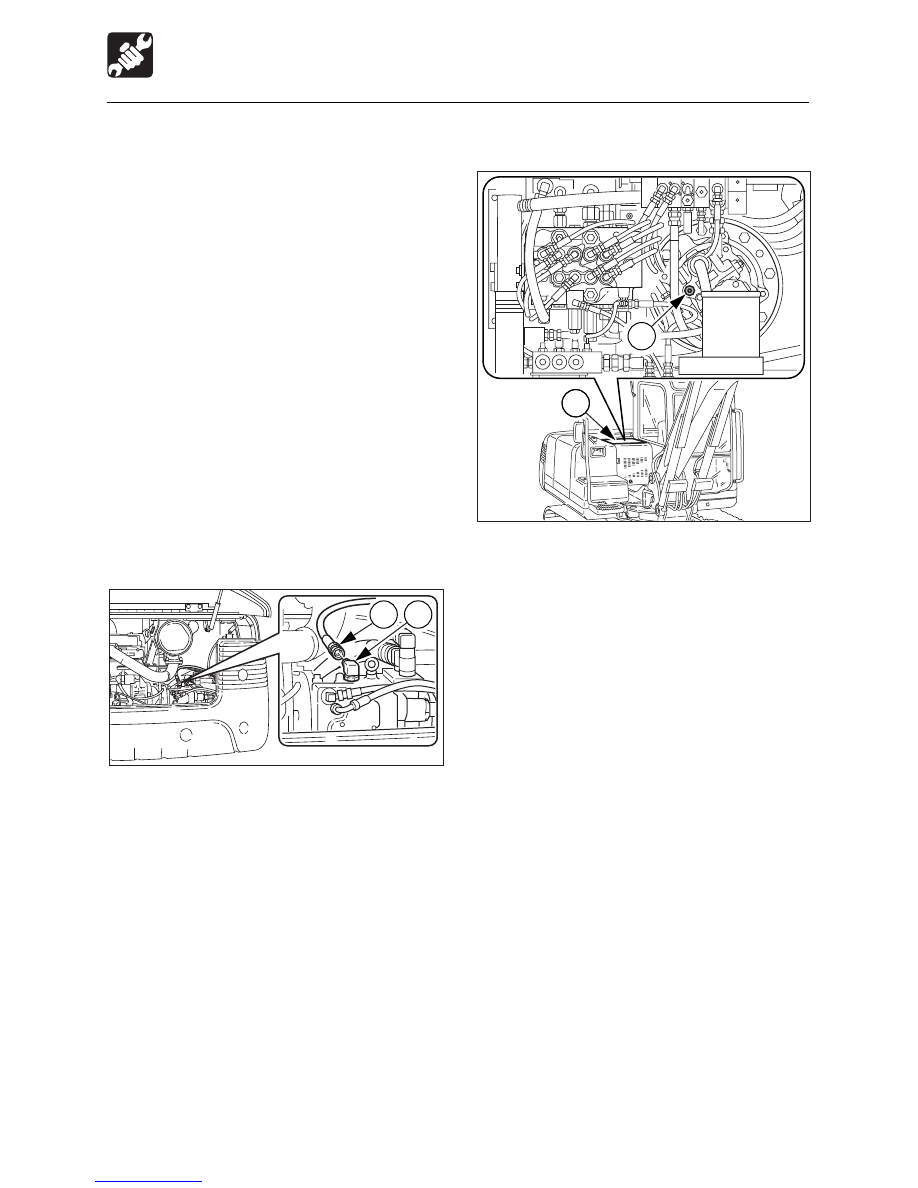
Bleeding the air

IMPORTANT: After replacing the
hydraulic oil, bleed the air from the
hydraulic circuit and hydraulic devices.
Failure to do so may damage the
hydraulic devices.

¡

¡

¡

¡

¡

Hydraulic pump

1. Open the engine hood.
2. Disconnect the drain hose (1) from the

hydraulic pump.

3. Once hydraulic oil overflows from the

elbow (2), connect the drain hose (1).

¡

¡

¡

¡

¡

Slew motor

1. Loosen the bolts and remove the center

cover (1).

2. Remove the plug (2).
3. Once hydraulic oil overflows from the plug

hole, tighten the plug (2).

4. Install the center cover (1).

¡

¡

¡

¡

¡

Cylinders

1. Start the engine and run it at low idle for

10 minutes.

2. Set the engine to a low idle, then extend

and contract all the cylinders 4 or 5 times,
without going to the stroke end.

3. Run the engine at high speed, then extend

and contract all the cylinders 4 or 5 times,
without going to the stroke end.

4. Set the engine back to a low idle, then

extend and contract all the cylinders 4 or
5 times to the stroke ends.

L3G021

2

1

L3G0261

2

1


129

MAINTENANCE

Every 2000 Hours

Inspecting the Engine Fuel
Injection Timing

This operation requires experience. Have it
performed by a Takeuchi sales or service
outlet.

Inspecting the Engine Fuel
Injection Valve

This operation requires experience. Have it
performed by a Takeuchi sales or service
outlet.


130

MAINTENANCE

When Required

Replacing the Bucket Teeth and
the Side Cutters

Replace the bucket teeth and the side cutters
when the tooth points or the side cutters are
worn, before the adapter or the bucket is
damaged.

 WARNING

¡

¡

¡

¡

¡

Before performing maintenance or
repairs under the machine, set all
working equipment against the ground
or in the lowermost position.

¡

¡

¡

¡

¡

To  prevent unexpected movement,
securely block the working elements
when repairing or replacing the bucket
teeth and the side cutters.

¡

¡

¡

¡

¡

Wear required appropriate equipment
such as safety glasses when using
hammers, as metal fragments or other
objects can fly and cause serious
personal injury.

¡

¡

¡

¡

¡

Do not allow unauthorized personnel
in the work area.

¡

¡

¡

¡

¡

Bucket tooth

Removal
1. Clean the bucket and park the machine in

a flat, safe place where the ground is hard.

2. Set the bottom surface of the bucket flat

and lower it on a block so that the locking
pin can be knocked out.

3. Remove the key, then check that the

bucket is stable.

4. Remove locking pin (1) and remove point

(2).

5. Take out rubber pin lock (3) and check

whether it is still usable.

E ....... When these are cracks in the rubber

and it seems like the roller is about
to come off.

F ....... When the roller becomes dented

when pressed with a finger.

E4G044

F

E

E4G043

3

2

1

4

E4G042


131

MAINTENANCE

When Required

Installation

1. Push rubber pin lock (3) into welding

adaptor (4).

Do not let the rubber pin lock stick out past
the welding adapter surface.

2. Install point (2) onto welding adaptor (4).

• Insert the point so that the surface

behind the point’s pin hole is flush or
deeper than the surface behind the
welding adapter’s pin hole.

3. Drive in locking pin (1).

After driving in the locking pin, use a pin with
the same surface as the point surface. Do
not use worn locking pins.

¡

¡

¡

¡

¡

Side cutter

Installation

1. Insert the bolts from the inner of the bucket

and tighten the nuts.
Tightening torque: 241 N·m (178 ft-lb)

2. Caulk the bolts with a punch at three spots

along the periphery of the screw to prevent
the nuts from coming loose.

G4G026

E4G045

3

4

E4G046

4

2

E4G047

1

Improper

Proper

Proper


132

MAINTENANCE

When Required

Adjusting the Gap Between the
Bucket and Arm

 WARNING

¡

¡

¡

¡

¡

Before performing maintenance or
repairs under the machine, set all
working equipment against the ground
or in the lowermost position.

¡

¡

¡

¡

¡

To  prevent unexpected movement,
securely block the working equipment
when adjusting.

1. Ground the bucket as shown on the

diagram above in a stable position.

2. Check that the bucket dose not move, then

set the safety lock lever to the locked
position and stop the engine.

3. Slide the O-ring (1) to bring the gap (A)

into view and measure the width of the
gap (A).
The gap (A) should be 0.5 mm (0.02 in.)
Swing the buckte slightly to the left and
lightly press the arm point to the left side
of the bucket (the side without an adjuster).

4. Remove the three bolts (2), the end plate

(3) and flange (4).

5. Extract adjustment shim (5) from between

flange (4) and the bucket body according
to gap (A).
Adjustment shim thickness : 0.5 mm (0.02
in.)
Be careful that the gap is no less than 0.5
mm (0.02 in.) after adjustment.

Supplement
Example (for a gap of 2 mm or 0.08 in.):
2 mm – 0.5 mm (standard value)

= 1.5 mm (0.06 in)

In the above example, three shims (5) should
be removed.

6. Insert adjustment shim (5) removed in step

5 above between end plate (3) and flange
(4) and fasten it in place with the three
bolts (2).
• Tightening torque for bolts (2)

54.9 N·m (40.5 ft-lb.)

7. Return the O-ring (1) to their original

position.

E4G050

4

3

2

E4G051

A

5

4

3

2

5

1

E4G048

E4G049

A

1


133

MAINTENANCE

When Required

Inspecting and Replenishing the
Windshield Washer Fluid

Use a windshield washer fluid designed
specifically for motor vehicles.  Follow the
instructions including with the washer fluid.

Inspection
1. Open the cab door.
2. Inspect the washer tank (1) and add

washer fluid if the level is low.

Replenishment
1. Mix the washer fluid to the prescribed

concentration.

2. Remove the cap (2) and add washer fluid.
3. Reinstall the cap (2).

Draining the Water Separator

 WARNING

¡

¡

¡

¡

¡

Do not smoke or permit open flames
while handling fuel or working on the
fuel system.

¡

¡

¡

¡

¡

Stop the engine in a well-ventilated
place and allow it to cool down before
performing maintenance.

¡

¡

¡

¡

¡

Clean up spilled fuel immediately.

1. Open the right side cover.
2. Place a pan under the drain hose.
3. Open the drain cock (1) and drain the

water.

4. Close the drain cock (1).

Bleeding the air from the fuel system
Refer to page 145 “Bleeding the Air from the
Fuel System”.
Supplement: Air in the fuel system can
make it difficult to start the engine and cause
engine problems. Also bleed the air when
the fuel tank is emptied.

L3G032

3

2

1

2

1

G4G030


134

MAINTENANCE

When Required

2. Set the safety lock lever to the locked

position and stop the engine.

3. Remove the bolt (1).
4. Hammer pin (2) out of the bucket.
5. Remove the bucket.

Inspect the pin seal (3) and replace it if it
is deformed or damaged.  (See next
page.)

Installation

1. Set the bucket’s O-ring (4) as shown on

the diagram.

2. Line up pin hole (A) in the bucket with the

pin hole in the arm (5), and install the pin
(2).

Replacing the Bucket

 WARNING

¡

¡

¡

¡

¡

Before performing maintenance or
repairs under the machine, set all
working equipment against the ground
or in the lowermost position.

¡

¡

¡

¡

¡

If maintenance must be performed with
the engine running, always work as a
two person team with one person
sitting in the operator’s seat while the
other works on the machine.
• When performing maintenance, be

sure to keep your body and clothing
away from moving parts.

¡

¡

¡

¡

¡

Wear required appropriate equipment
such as safety glasses and filter mask
when using hammers, as metal
fragments or other objects can fly and
cause serious personal injury.

¡

¡

¡

¡

¡

When lining up the pin holes, always
do so by sight. Your finger may be cut
off if you stick it into the hole.

Removal

1. Ground the bucket as shown on the

diagram above in a stable position.

Supplement: When removing pins, set the
bucket so that it is just gently against the
ground. If it is strongly against the ground,
the resistance will be great and it will be
difficult to remove the pin.

E4G048

E4G052

5

4

3

1

2

E4G053

4

E4G054

6

B

A

5


135

MAINTENANCE

When Required

3. Operate the cylinder, line up pin hole (B)

in the bucket with the pin hole in the link
arm (6), and install the pin (2).

4. Line up the turn prevention holes, install

the bolt (1), and the nuts.
Be sure to leave a gap of about 0.5 ~ 1
mm (0.02 ~ 0.04 in.) between the nut and
bucket bush, or the nut will come loose.

5. Adjust the gap between the bucket and

the arm. Refer to page 132.

6. Slide the O-ring (4).

E4G055

0.5~1mm

1

E4G056

4

E4G057

3

Replacing the pin seal

1. Set the pin seal (3) in the direction shown

on the diagram above.

2. Use a mallet to slowly press the pin seal

in.  Be careful not to damage the seal.


136

MAINTENANCE

When Required

L3G022

B

A B

1

Lubricating the Levers

 WARNING

Set the machine to the parking posture,
stop the engine, remove the starter key
and store it.  Failure to do so may result
in the machine moving abruptly, leading
to serious injury or death.

If the levers or pedals no longer move
smoothly, supply grease.

Operating levers

1. Remove the lower mount section of the

boot (1) and turn it upwards.

2. Wipe off the old grease.
3. Supply grease to points (A) and (B).
4. Set the boot (1) back as it was.

Travel levers

1. Remove the lower mount section of the

boot (1) and turn it upwards.

2. Wipe off the old grease.
3. Supply grease to points (A) and (B).
4. Set the boot (1) back as it was.

E4G058

1

A

B

Boom swing pedal

1. Remove the lower mount section of the

boot (1) and turn it upwards.

2. Wipe off the old grease.
3. Supply grease to points (A) and (B).
4. Set the boot (1) back as it was.


137

MAINTENANCE

When Required

Inspecting the Rubber Crawlers

Repair or replace the rubber crawlers if their
conditions are as described below. Consult
a Takeuchi sales or service outlet about
repairs or replacement.

Rubber crawler
Replace the crawler if the entire crawler is
stretched and cannot be adjusted.

(1) Lug

Replace if the height of (A) is 5 mm (0.2 in.)
or below.

(2) Steel cord

Replace if the steel cord is exposed over 2
or more links.
Replace if half or more of the steel cords on
one side are cut.

(3) Metal core

Replace if even one metal core is off.

(4) Rubber

Repair if there are cracks of 60 mm (2.4 in.)
or greater in length.
If the steel cord is visible, repair as soon as
possible, regardless of the length of the
crack.

60 mm or greater

E4G065

E4G064

3

E4G062

3

2

1

A

4

E4G063

2


138

MAINTENANCE

Removal

1. Start the engine and raise the machine

body with the hoe attachment and dozer
blade.

2. Stop the engine.

3. Remove the valve covers (1) at the center

of the left and right crawler frames.

4. Loosen the lock plate (2) counterclockwise.
5. Turn the valve handle (3) counterclockwise

to loosen the tension of the crawler.

6. Once the crawler is completely loose,

tighten the valve handle (3).

7. Tighten the lock plate (2).
8. Do the same for the other side.

When Required

Replacing the Rubber Crawlers

 WARNING

¡

¡

¡

¡

¡

If you must work beneath the raised
machine or equipment, always use
wood blocks, jack-stands or other rigid
and stable supports. Never get under
the machine or working equipment if
they are not sufficiently supported.
This procedure is especially important
when working on hydraulic cylinders.

¡

¡

¡

¡

¡

If maintenance must be performed with
the engine running, always work as a
two person team with one person
sitting in the operator’s seat while the
other works on the machine.
• When performing maintenance, be

sure to keep your body and clothing
away from moving parts.

This machine uses a hydraulic cylinder to
adjust the tension of the crawler belts. Note
that it is not necessary to regularly perform
adjustments of the tension of the belt itself.

IMPORTANT: During the replacement
procedure, only start the engine when
raising and lowering the machine body.
Otherwise, always keep the engine off.
IMPORTANT: When the travel speed
switch is set to the 2nd speed side while
the engine is running, the tensioning
cylinder rods extend and the crawlers are
tightened.


139

MAINTENANCE

When Required

Installation
1. Engage the crawlers with the left and right

sprockets.

2. Set the left and right crawlers on the idlers.
3. Start the engine.
4. Press the travel speed switch once and

set it to the 2nd speed side. The left and
right crawlers are tightened
simultaneously.

5. Check that the crawlers are properly

tightened. Standard value (A).
Refer to page 115 “Inspecting the Crawler
Tension”.

9. Slowly lower the dozer blade side of the

machine body, by the dozer blade lever.
(Do not start the engine.)

10. Ground the crawlers and lower the

machine body so that the crawler slack
is maximum.

11. When the crawlers come away from the

idlers, slide the crawlers to the outside
and remove them.

12. Disengage the crawlers and sprockets,

then remove the crawlers from the
crawler frames.


140

MAINTENANCE

Long-term Storage

During storage

 WARNING

¡

¡

¡

¡

¡

Do not operate the engine in an
enclosed area without adequate
ventilation.

¡

¡

¡

¡

¡

If natural ventilation is poor, install
ventilators, fans, exhaust extension
pipes or other artificial venting devices.

1. To prevent rusting, operate the machine

once a month so that the oil is fully
circulated.

2. Inspect the battery and recharge it if

necessary.
Have the battery charged by a Takeuchi
sales or service outlet.

Starting the machine after storage

IMPORTANT: If  the “Procedures for
storage” have not been performed and
the machine has been stored for a long
period of time, consult a Takeuchi sales
or service outlet before reusing the
machine.

1. Wipe off the rust-prevention oil that was

applied to the hydraulic oil cylinders’ piston
rods.

2. Add fuel, oil and grease to all parts.

Procedures for storage
If the machine is to be stored for 30 days or
more, store it indoors.  If it must be stored
outdoors, stop it on wood laid out on a flat
surface and place a waterproof cover over it
so that it stays dry.
1. Clean the machine.
2. Inspect for oil leakage, water leakage and

loose nuts and bolts.

3. Add fuel and replace the hydraulic oil and

oil.

4. To prevent rusting and freezing, replace

the engine coolant with long-life coolant
(LLC).
Refer to page 124 “Cleaning the Engine
Cooling System”.

5. Use the grease gun to supply grease to

the grease nipples.

6. Fully contract the bucket and arm cylinders

and ground the bucket and dozer blade.

7. Apply rust-prevention oil to the hydraulic

cylinder rods.

8. Disconnect the cable from the battery’s

“–” terminal and cover the battery to
prevent freezing.


141

Symptoms that are not Malfunctions ...... 142

If the Engine Overheats ........................... 143

If the Battery Goes Dead .......................... 144

After the Fuel Runs Out ........................... 145

If a Fuse Blows ......................................... 146

If a Warning Lamp Flashes ...................... 148

Other Symptoms ...................................... 150

To Lower the Boom .................................. 152

Towing ...................................................... 153

TROUBLESHOOTING


142

TROUBLESHOOTING

Symptoms that are not Malfunctions

The following symptoms are not
malfunctions:

¡

When the arm reaches the vertical position
while contracting it while the engine is
running at low speed, the contracting
speed slows down momentarily.

¡

When the bucket teeth reach the
horizontal position while the engine is
running at low speed, the speed of bucket
movement slows down momentarily.

¡

The slew motor produces noise at the
beginning and end of the slewing
operation.

¡

The travel motor produces noise when
stopped suddenly during high speed
travel.

¡

The control valve produces noise if
excessive force is applied to the working
equipment and when the stroke end is
reached.

¡

When the bucket is operated while making
a right pivot turn (i.e., when only the left
crawler is turning), the speed of the pivot
turn may suddenly increase.

¡

Performance decreases when an
attachment weighing more than a
standard arm or bucket is mounted.

E4J001

E4J002


143

TROUBLESHOOTING

If the Engine Overheats

 WARNING

¡

¡

¡

¡

¡

Do not open the engine hood when
there is steam coming from the engine
room. The steam or hot water may
spurt out, resulting in burns.

¡

¡

¡

¡

¡

Do not remove the radiator cap or drain
plugs when the coolant is hot. Stop the
engine, let the engine and radiator cool
and loosen the radiator cap or drain
plugs slowly.

¡

¡

¡

¡

¡

Stop the engine and allow the machine
to cool down before performing
inspection and maintenance.

The following symptoms indicate
overheating:

¡

An alarm is sounded and the coolant
temperature warning lamp, engine
emergency lamp flashes.
When the engine oil pressure/coolant level
warning lamp is flashing simultaneously,
the coolant level is low.

¡

The water temperature gauge is in the red
zone.

¡

The engine slows down and the force
decreases.

¡

Steam comes from the engine room.

Procedure
1. Park the machine in a safe place.
2. Inspect whether the engine oil pressure/

coolant level warning lamp is flashing or if
there is steam coming out when the
engine hood is closed.

3. If there is steam, stop the engine

immediately and contact a Takeuchi sales
or service outlet for repairs.
If the engine oil pressure/coolant level
warning lamp is off, run the engine at low
idle and let the water temperature
decrease.

4. Once the water temperature gauge drops

to the green zone, stop the engine.

5. Once the engine is cool, perform the

following inspections and procedures:

¡

Fan belt slack ......................... Adjust.

Refer to page 114.

¡

Coolant level .............................. Add.

Refer to page 107.

¡

Water leakage ........................ Repair.

¡

Radiator fins ............................ Clean.

Refer to page 121.

¡

Sediment in cooling system ..... Clean.

Refer to page 124.

If the problem persists after the above
procedures are taken, contact a Takeuchi
sales or service outlet for repairs.

L3J001


Content      ..     7      8      9      10     ..