Takeuchi Hydraulic Excavator TB175 (No. 17512105~). Operator's Manual (2007) - page 3
 

  Index      Manuals     Takeuchi Hydraulic Excavator TB175 (No. 17512105~). Operator's Manual (2007)


Search            copyright infringement  


Content      ..     1      2      3      4      ..


Takeuchi Hydraulic Excavator TB175 (No. 17512105~). Operator's Manual (2007) - page 3


32

SAFETY

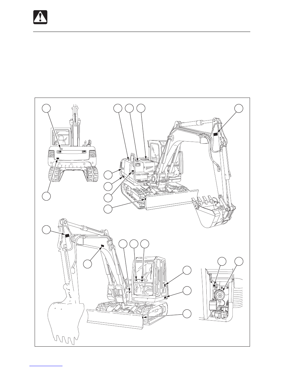
Safety Signs (Decals)

The following safety signs (decals) have been placed on your machine in the areas indicated.
They are intended for the personal safety of you, and those working with you. Please take
this manual, walk around your machine and note the content and location of these safety
signs. Review these signs and the operating instructions in this manual with your machine
operators.

¡

Keep the signs legible. If they are not, obtain replacements from your Service outlet.

L3A0033

7

11

1

2

1

5

1

2

1

12

12

12

10

3

4

13

9

2

8

6


33

SAFETY

Safety Signs (Decals)

1. No.03593-06500

2. No.03593-07400

3. No.03593-13700

7. No.05693-21980

9. No.03993-00400

Position of Fire extinguisher

4. No.03593-47010

5. No.03593-47020

6. No.03393-75040

D O   N OT

e n t e r   i n t o

sw i n g i n g   a r e a

WARNING

CAUTION

03593-07400

STOP ENGINE

BEFORE OPENING

WARNING

This machine,if improperly operated or 
maintained can cause bodily harm,or even
DEATH.
Read and understand the owners manual
supplied with this machine before operating.
Keep all safety devices in place and 
functional.
Do not operate the machine unless the seat
belt is properly fastened around you.

Follow the instructions in the Operator’s 
Manual when hoisting the machine or  
fastening it to the transport vehicle.

03593-13700

1 -

2 -

3 -

4 -

5 -

WARNING

05693-21980

Engine  may  be  HOT

WARNING

03593-47010

THIS EXCAVATOR

MUST NOT BE USED

AS A CRANE

WARNING

03593-47020

WHEN BUCKETS WIDER THAN STANDARD
ARE FITTED TO THIS MACHINE,
CAB(CANOPY)DAMAGE MAY OCCUR WHEN
FULL LEFT HAND BOOM OFFSET IS USED.

CAUTION

03393-75040

DO NOT USE ETHER

USAGE OF ETHER FOR STARTING 
PURPOSES MAY CAUSE INTERNAL 
ENGINE DAMAGE.

8. No.05693-53810

05693-53810

Setting this switch to the “OFF” 

position will shut down all of 

the electrical circuits and the 

memory of the radio preset 

tuning buttons will be deleted.

CAUTION

Except for UK


34

SAFETY

Safety Signs (Decals)

11. No.03593-06700

Hydraulic oil

10. No.03593-06600

Diesel Fuel

13. No.05693-52528

for EU
Noise Outside the Cab
This value indicates the noise level
outside the machine and refers to the
noise perceived by the persons who
are in the vicinity of the work area.

12. No.03993-00500

Position of Hoisting

Diesel Fuel Only

03593-06600

D

Serial No. 17514412 ~
No.05693-49035


35

Names of Components .............................. 36

Doors and Covers ...................................... 38

Seat and Seat Belt ...................................... 43

Instrument cluster ...................................... 46

Switches ..................................................... 48

Levers and Pedals ..................................... 53

Accessories ............................................... 55

CONTROLS


36

CONTROLS

Names of Components

Upperstructure
1. Cab
2. Seat
3. Engine hood
4. Fuel tank
5. Hydraulic tank

Undercarriage
  6. Crawler belt
  7. Idler
  8. Track roller
  9. Carrier roller
10. Travel motor

Working equipment
11. Bucket
12. Bucket cylinder
13. Arm
14. Arm cylinder
15. Boom
16. Boom cylinder
17. Boom bracket
18. Swing cylinder
19. Auxiliary hydraulic lines
20. Dozer blade
21. Blade cylinder
22. Intermediate boom
23. Boom adjustment cylinder

Mono-Boom

2-Piece Boom

19

11

13

12

9

15

7

16

5

4

10

18

17

1

8

3

2

6

14

21

20

L3B001

15

23

16

22

L3L0151


37

CONTROLS

Names of Components

  1. Instrument cluster
  2. Starter switch
  3. Light switch
  4. Horn button
  5. Travel speed switch
  6. Wiper switch
  7. Safety lock lever
  8. Slew speed switch
  9. Power mode buttons

Throttle buttons

10. Left operating lever
11. Right operating lever
12. Fuse box

13. Boom swing pedal
14. Travel lever
15. Auxiliary hydraulic switches
16. Blade lever
17. Decel. button
18. Fan switch (Heater)
19. Heater / Defroster switch
20. Ventilation/Circulation switch
21. Cigarette lighter
22. Selector Button (2-Piece boom)
23. Pedal lock
24. Intermediate boom operation indicator

lamp (2-Piece boom)

L3B0022

16

24

2

8

21

3

12

9

6

10

15

14

14

17

13

7

5

18

4

11

19

20

23

1

22


38

CONTROLS

Doors and Covers

Starter Key

The starter key is used not only to start and
stop the engine, but also to lock and unlock
the following places:

¡

Fuel filler cap

¡

Cab door

¡

Covers

Opening
1. Pull the knob (1) towards you and open

the door.
To open the door from inside the cab, push
the lever (2) to the front.

2. Open the door fully and press it against

the cab to lock it in place.

Closing

1. Either push release lever (3) to the front

or lower release lever (4).

2. Close the released door.

Cab Door

 WARNING

When mounting and dismounting the
cab, first open the door fully to the locked
position and check that it does not move.

Open the door fully and press it against the
catch at the back of the door to lock it in place.
Always lock the door when mounting and
dismounting and when operating the
machine.

Lock and unlock

1. Insert the starter key and turn it.

E4B003

4

3

C4C002

C4C001

2

1

Front Window

 WARNING

¡

¡

¡

¡

¡

Grasp the handles firmly with both
hands when opening and closing the
front window. Your head or hands may
get caught if they slip.

¡

¡

¡

¡

¡

If you open the front window, be sure
to lock it in place with the lock pins on
the left and right sides. The window
may fall if it is not locked in place.


39

CONTROLS

Doors and Covers

Opening

1. Park on a level surface and stop the

engine.

2. Set the safety lock lever to the locked

position.

3. Pull the left and right lock pins (1) to the

inside then turn them to the locked position
to unlock the front window. If the lock pins
(1) are partially sticking out they may
cause damage.

4. Grasp the lower handle (2) with the left

hand, the upper handle (3) with the right
hand, then lift and slide to the rear.

5. Once the window frame is against the

stopper, move the lock pins (1) to the
outside to lock front window.

Closing

 WARNING

When closing the front window, lower the
window slowly so as not to hit your head.
Lowering the window abruptly may result
in injury or damage the front window.

1. Pull the left and right lock pins (1) to the

inside and turn them to the locked position
to unlock the front window. If the lock pins
(1) are partially sticking out they may
cause damage.

2. Grasp the front (lower) handle (2) with the

left hand, the rear (upper) handle (3) with
the right hand, then slowly lower the front
window.

3. Move the lock pins (1) to the outside to

lock the front window.

1

1

1

1

3

C4C003

Released

Locked

1

1

2

3

C4C004

Lower Front Window

Removing

1. Open the front window and stow it in the

ceiling.

2. Grasp the protruding parts (4) on the left

and right with your fingers and slowly lift
the lower front window off.

3. Hold the glass firmly, place the lower front

window through the guides (5) at the rear,
then set it on the supports (6) and fasten
it in place.

C4C005

4

4

4

5

6

6

4

5

C4C006


40

CONTROLS

Side Window

1. Grasp the catch (7), unlock it and open

the side window.

2. To close the side window, close it until a

click is heard.

Front Cover (Tool Box)

 CAUTION

¡

¡

¡

¡

¡

Never jump off the machine. Use the
steps and handrails when climbing on
and off the machine, and always
support your body at three points with
your hands and feet.

¡

¡

¡

¡

¡

When opening the front cover, open it
firmly to the stopped position.

¡

¡

¡

¡

¡

When opening and closing the front
cover, be careful not to get your hands
or other parts of your body caught.

The grease gun and tools are stored under
the cover.

Doors and Covers

Opening
1. Insert the starter key and turn it

counterclockwise to unlock the front cover
(1).

2. Tilt the front cover (1) until it stops.

Closing
1. Support the front cover (1) by hand and

release the stay (2).

2. Close the front cover (1).
3. Insert the starter key and turn it clockwise

to lock the front cover (1).

L3B007

2

1

7

C4C007

L3B054

1

2

3

Side Covers

 CAUTION

¡

¡

¡

¡

¡

When opening the side cover, open it
firmly to the locked position.

¡

¡

¡

¡

¡

When opening and closing the side
cover, be careful not to get your hands
or other parts of your body caught.

Opening
1. Insert the starter key and turn it

counterclockwise to unlock the side cover.

2. Lift the side cover fully until it stops.
3. Press the stay (2) to fix the side cover.

Engine hood unlock knob (3) is located
behind the right side cover.


41

CONTROLS

Doors and Covers

Engine Hood

 WARNING

Before opening the engine hood, be sure
to stop the engine. If your hands or tools
should get caught in the fan or fan belt
while the engine is running they may be
severed.

Opening
1. Open the right side cover and pull the

unlock knob (3).
Refer to “Side Covers”.

2. Lift the engine hood (1) fully.

Closing
1. Close the engine hood and press it down

until a click is heard at the front.

Maintenance Cover

 WARNING

¡

¡

¡

¡

¡

Before opening the maintenance cover,
stop the engine.

¡

¡

¡

¡

¡

When maintenance on the machine,
clean up the foot area and strictly
observe the following so as not to fall:
• Do not spill oil or grease.
• Do not leave tools laying around.
• When walking, watch your step.

¡

¡

¡

¡

¡

Never jump off the machine. Use the
steps and handrails when climbing on
and off the machine, and always
support your body at three points with
your hands and feet.

¡

¡

¡

¡

¡

Use protective equipment as required
by job conditions.

Opening
1. Insert the starter key and turn it

counterclockwise to unlock the
maintenance cover (1).

2. Pull the knob (2), then lift the maintenace

cover (1) fully until it stops.

Closing
1. Support the maintenance cover (1) by

hand and release the stay (3).

2. Close the maintenance cover (1).
3. Insert the starter key and turn it clockwise

to lock the maintenance cover (1).

L3B009

1

1

2

L3B053

3

Closing
1. Support the side cover (1) by hand and

release the stay (2).

2. Close the side cover (1) and press it down

until a click is heard at the front.


42

CONTROLS

Doors and Covers

Fuel Filler Cap

 WARNING

¡

¡

¡

¡

¡

Never jump off the machine. Use the
steps and handrails when climbing on
and off the machine, and always
support your body at three points with
your hands and feet.

¡

¡

¡

¡

¡

Do not smoke or permit open flames
while fueling or near fueling
operations.

¡

¡

¡

¡

¡

Supply fuel in a well ventilated place
and with the engine stopped.

¡

¡

¡

¡

¡

Clean up spilled fuel immediately.

¡

¡

¡

¡

¡

Do not fill the fuel tank to capacity.
Allow room for expansion.

¡

¡

¡

¡

¡

Tighten the fuel filler cap securely.

Opening
1. Open the key cover, insert the key and

turn it clockwise to unlock the fuel cap.

2. Turn the fuel cap counterclockwise and

remove it.

Closing
1. Set the fuel cap in place and turn it

clockwise.

2. Turn the key counterclockwise to lock the

fuel cap, then remove the key.

L3B011E

Close

Open


43

CONTROLS

Seat and Seat Belt

Seat

 WARNING

Adjust, secure and latch the operator’s
seat.

(A) Lumber adjustment
1. Turning knob (1) in the direction of the

arrow causes the lumber of the backrest
to curve outwards for greater back support.

2. Turning the knob (1) further then removes

the curve and returns the seat to its original
position.
The knob (1) cannot be turned counter to
the direction of the arrow.

(B) Seat cushion angle and height

adjustment

¡

Lift lever (2) to adjust the rear angle of the
seat cushion.

1. To raise the rear angle of the seat cushion,

raise yourself slightly off the seat while
lifting the lever.

2. To lower the rear angle of the seat cushion,

apply your weight to the rear of the seat
cushion while lifting the lever.

¡

Lower lever (2) to adjust the front angle of
the seat cushion.

1. To raise the front angle of the seat cushion,

apply your weight to the backrest while
holding the lever down.

2. To  lower the front angle of the seat

cushion, apply your weight to the front of
the seat cushion while holding the lever
down.

¡

To adjust the height of the seat, adjust the
front and rear angles of the seat cushion
alternately.
(5 steps, 60 mm (2.36 in.) adjustment
range)

Example: First raise the front angle of the

seat cushion, then raise the rear
angle of the seat cushion by the
same amount. This raises the
height of the seat.

¡

After adjusting to the desired position,
release the lever to lock it.

(C) Back angle adjustment

 WARNING

¡

¡

¡

¡

¡

Do not set the seat back to its
maximum reclining position and slide
the seat backwards at the same time.
Doing so may break the rear window
glass, resulting in injury.

¡

¡

¡

¡

¡

Be careful not to allow the force of the
spring to bring the seat back sharply
forward.

1. Raising your torso, sitting down firmly in

the seat.

2. Pulling lever (3) allows you to use the

pressure of the springs in the seat pressing
against your back to adjust the reclining
angle of the seat back. Release the lever
(3) at the desired angle and the seat back
will remain fixed in that position.

6

1

7

4

3

L3B012

2

5

A

D

F

G

C

B

E


44

CONTROLS

Seat and Seat Belt

(D) Fore-and-aft adjustment
1. Pull on lever (4) and slide the seat

backward or forward to bring it to the
optimum position for operating the
machine.

2. Release the lever (4) at the desired

position and the seat will remain fixed
there.
Adjustment stroke: 17 steps,160 mm (5.9 in.)

(E) Weight adjustment
1. Turn handle (5) and set it to indicate the

weight of the person to operate the
machine.
May be set to any value from 50 to 120 kg
(110 to 265 lbs.)

(F) Lever stand adjustment
1. Pull on lever (6) and slide the lever stand

backward or forward to bring it to the
optimum position for operating the
machine.

2. Release the lever at the desired position

and the lever stand will remain fixed there.
Adjustment stroke: 70mm (2.8 in.)

(G) Headrest adjustment
The position of the headrest (7) can be
adjusted in the up and down directions.
1. Grasp the headrest with both hands and

move it upwards or downwards.

6

3

L3B013

2

5

4

E


45

CONTROLS

Seat Belt

 CAUTION

Always fasten the seat belt securely
before starting the engine.

Fastening the seat belt
1. Adjust the seat to the optimum position

for operating, raise your torso, and sit back
firmly into the seat.

2. Pull the seat belt to the desired length.

3. Make sure that the belt is not twisted and

then insert the tongue plate (A) into the
buckle (B) of the seat belt until you hear a
clicking sound as it locks in place.

Releasing the seat belt

1. To remove the seat belt, simply press the

button (C) located on the buckle.
The seat belt is automatically stowed
away.

Seat and Seat Belt

E4B023

B

A

E4B024

C


46

CONTROLS

Instrument Cluster

Warning Lamps

IMPORTANT: If  a warning lamp flashes
and an alarm is sounded, stop all
operations immediately and inspect and
maintain the appropriate part.

Refer to page 148 “Troubleshooting”.

1. Engine Emergency Lamp

This lamp flashes and an
alarm is sounded if the
engine oil pressure or the
coolant level in the radiator

drops or the coolant temperature rises
abnormally while the engine is running. After
approximately 5 seconds, the engine stops
or low idling automatically.

2. Engine Oil Pressure / Coolant Level

Warning Lamp

This lamp flashes and an
alarm is sounded if the
lubricant oil pressure or
coolant level in the radiator

drops abnormally while the engine is running.

3. Coolant Temperature Warning Lamp

This lamp flashes and an
alarm is sounded if the
engine coolant temperature
rises abnormally while the

engine is running.

4. Battery Charge Warning Lamp

This lamp flashes and an
alarm is sounded if a
problem arises in the
charging system while the

engine is running.

5. Air Cleaner Warning Lamp

This lamp flashes and an
alarm is sounded if the air
cleaner filter is clogged while
the engine is running.

6. Water Separator Warning Lamp

This lamp flashes and an
alarm is sounded if the water
is detected within the water
separator while the starter

switch is in the ON position.

7. Fuel Level Warning Lamp

This lamp lights when the
fuel level is low while the
starter switch is in the ON
position.

G4B009

C4B012

C4B030

G4B010

L3B036

L3B015

L3B016

L

FC

H

1

4

2

3

6

7

12

9

8

13

14

5

10

11

L3B014


47

CONTROLS

Instrument Cluster

Meters

12. Hour Meter

This displays the total engine
running time in hours.
The rightmost digit indicates
tenths of hours (6 minutes).

Set the inspection and maintenance intervals
according to the time displayed on the hour
meter.

13. Water Temperature Gauge

This gauge indicates the
temperature of the engine
coolant water.
The needle should be within

the green range during machine operation.
The red range indicates overheating.

14. Fuel Gauge

This gauge indicates the
amount of fuel in the tank.
Be sure to top off the tank
before running out of fuel.

C4B014

Indicators

8. Glow Lamp

This lamp turns off when
engine preheating is
completed.

9. Travel Speed Lamp

This lamp lights when the
travel speed switch is set to
2nd (high speed).

10. Slow Speed Slew Lamp

This lamp lights when slow
speed slew switch pressed,
the slew speed decreases.

11. Power Mode Lamp

These lamps indicates the
engine speed.

L3B017

L3B018

L

FC

H

L3B019

L3B020

L3B021

C4B013


Content      ..     1      2      3      4      ..