Takeuchi Mini Excavator TB216 (No.216000002~, No.216100002~). Operator's Manual - page 2
Safety
Precautions on maintenance
Periodically replace the safety-critical
Jump starting with booster cables
parts
• When starting the engine using the booster
• To use the machine safely for a longer
cables, be sure to connect the cables in
period, periodically add oil and perform
the proper order described below. Wrongly
inspection and maintenance. To improving
connected cables can result in sparking
the safely, replace the safety-critical parts
and battery explosion.
like hoses and seat belts periodically. Refer
· Do not allow the “machine in trouble” and
to “Safety-critical parts to be replaced
“rescue machine” to touch each other.
periodically” for further details.
· Do not allow the positive (+) and negative
• The “Safety-critical parts to be replaced
(-) clips of the booster cables to touch
periodically” are the parts which
each other or to come in contact with the
deteriorate, wear and fatigue after repeated
machine.
use and whose properties change over
· When connecting, attach the positive
time. While these characters of these parts
booster cable to the positive (+) terminals
could cause serious physical or personal
first. When disconnecting, remove the
damage, judging the remaining life of these
negative cable from the negative (-)
part are difficult from external inspection or
terminal (ground) first.
the feeling when operating.
· Be sure to connect the clips securely.
• Replace the “Safety-critical parts to be
· Connect the last clip of the booster cable
replaced periodically” if any defect is found
to a point as far away from the battery as
from external inspection, even when they
possible.
have not reached the time specified
• Always wear the protective goggle and
interval.
gloves when starting the engine by using
the booster cables.
• Use the booster cables and clips of a size
suited to the capacity of battery. Do not
use damaged or corroded booster cables
and clips.
• Be sure that the battery of the “rescue
machine” has the same capacity as the
battery of the “machine in trouble”.
1-33
Safety
Precautions on maintenance
Have a Takeuchi service agent repair
Disposing of wastes
welding
If welding must be performed, make sure
that it is done by a qualified person in a
properly equipped workplace. To prevent any
part from breaking down or being damaged
due to overcurrent or sparks, observe the
following.
• Disconnect the wiring from the battery
before doing electric welding.
• Do not continuously apply 200 V or more.
• The earth ground must be connected
within one meter from the welding section.
• Always collect oil that is drained from the
Do not connect the earth ground near to
machine in containers. Improperly
an electronically controlled device/
disposed waste oil can cause
instrument or connectors.
environmental harm.
• Make sure that there are no seals or
• Follow appropriate laws and regulations
bearings between the welding section and
when disposing of harmful objects such as
the earth ground.
oil, fuel, coolant, solvent, filters and
• Do not connect the earth ground around
batteries.
the pins for the working equipment or
hydraulic cylinders.
• When welding is to be done on the
Handling of poisonous chemicals
machine body, disconnect the connectors
for the electronically controlled devices
Poisonous chemicals will cause serious injury
before working.
if directly contacted.
Poisonous chemistry used in this machine
includes grease, battery solution, coolant,
Vibrations operators are subject to
paint and adhesive agent.
Handle the poisonous chemicals properly
According to the results of the tests
with care.
conducted to determine the vibrations
transmitted to the operator by the machine,
the upper limbs are subjected to vibrations
lower than 2.5 m/s2 (8.2 ft/s2) while the
seated part of the body is subjected to
vibrations lower than 0.5 m/s2 (1.64 ft/s2).
Checks after maintenance
• Gradually increase the engine speed from a
low idle to maximum speed and check that
there is no oil or water leaking from the
serviced parts.
• Operate each control lever and check that
the machine is operating properly.
1-34
Safety
Safety signs (decals)
Safety signs (decals)
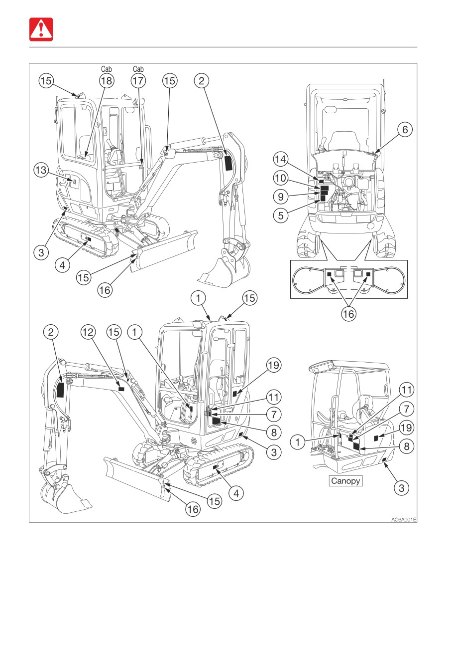
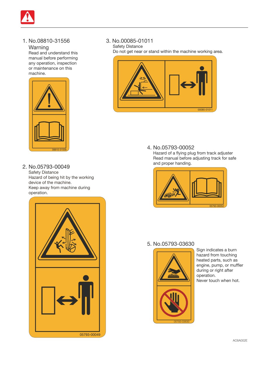
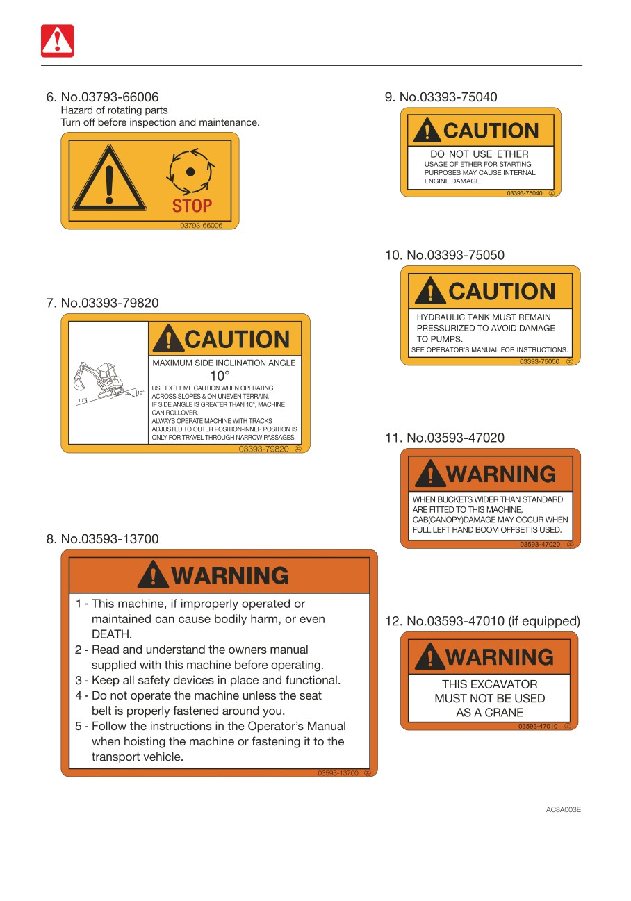
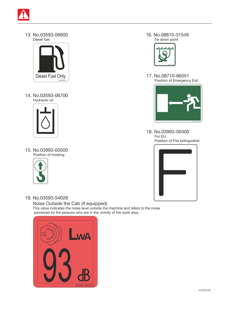
For the safety of the operator and the personnel working around the site, safety signs (decals)
are placed at certain locations on the machine as shown below. Walk around the machine with
this manual, and check the content and location of these safety signs. Review these signs and
the operating instructions in this manual with your machine operators.
• Keep the signs clean and legible. If any of the safety labels is peeling or damaged and
becomes difficult to read, replenish it with a new one. Please include your product serial
number when ordering a new sign from the Takeuchi service agent.
• When a part/unit to which a safety sign is attached is replenished, a new sign must be
attached to the new part/unit.
1-35
Safety
Safety signs (decals)
1-36
Safety
Safety signs (decals)
1-37
Safety
Safety signs (decals)
1-38
Safety
Safety signs (decals)
1-39
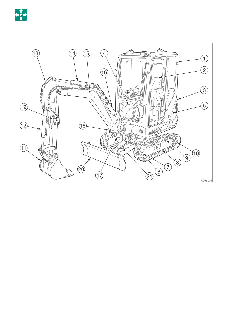
Controls
Names of components (Cab)
Names of components (Cab)
Upperstructure
Undercarriage
Working equipment
1. Cab
6. Crawler belt
11. Bucket
2. Seat
7. Idler
12. Bucket cylinder
3. Engine hood
8. Track roller
13. Arm
4. Fuel tank
9. Shoe slide
14. Arm cylinder
5. Hydraulic tank
10. Travel motor
15. Boom
16. Boom cylinder
17. Boom bracket
18. Swing cylinder
19. Auxiliary hydraulic lines
20. Dozer blade
21. Blade cylinder
2-2
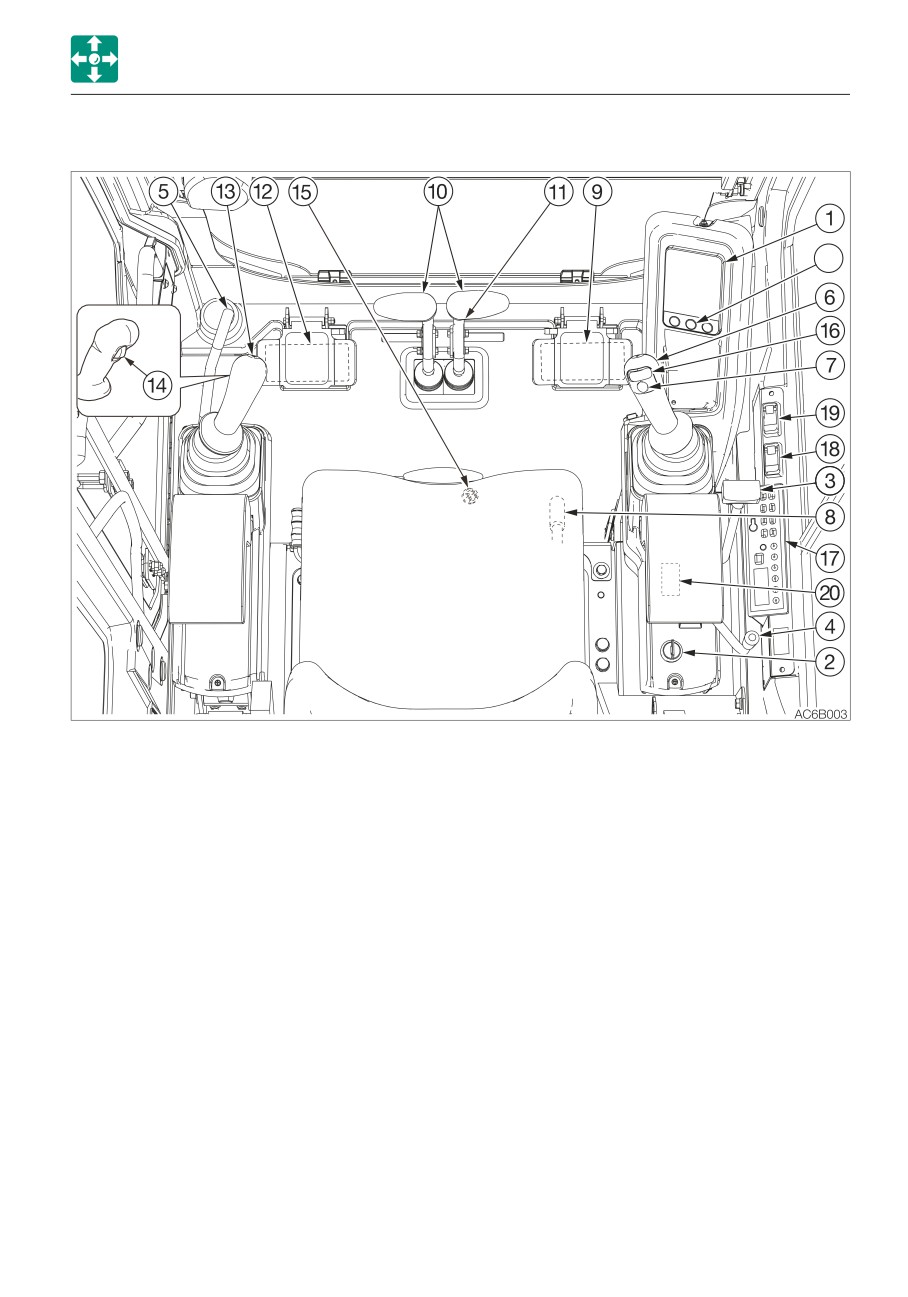
Controls
Names of components (Cab)
21
1. Instrument cluster
11. Travel speed switch
2. Starter switch
12. Auxiliary hydraulic pedal
3. Blade lever
13. Left operating lever
4. Throttle lever
14. Third auxiliary hydraulic button*
5. Safety lock lever
15. Third auxiliary hydraulic switch*
6. Right operating lever
16. Auxiliary 2nd switch*
7. Horn button
17. Radio
8. Selector lever
18. Heater fan switch
9. Boom swing pedal
19. Wiper switch
10. Travel lever/Pedal
20. Lift overload warning switch*
21. Light switch
*: Subject to the specifications or optional products selected
2-3
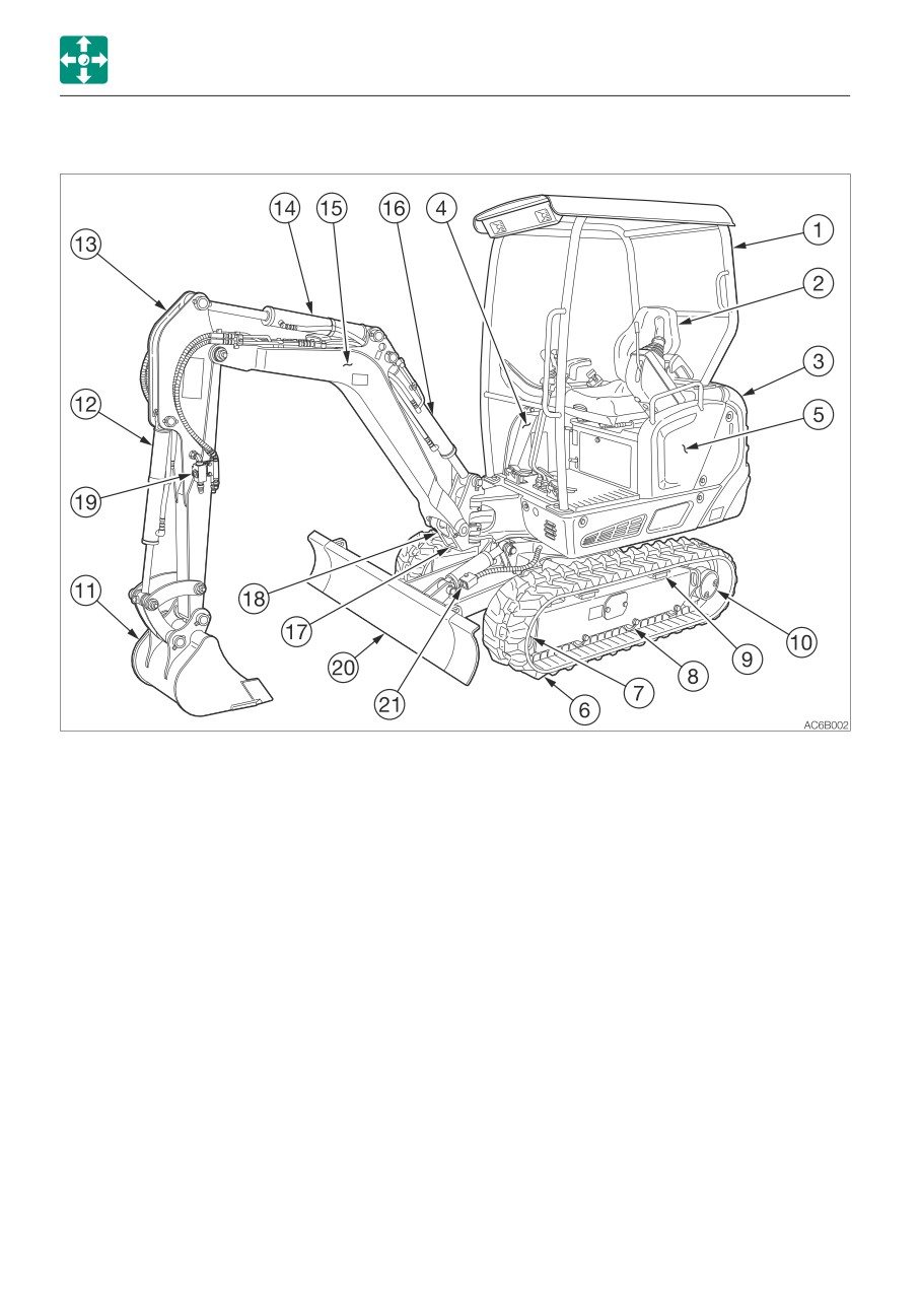
Controls
Names of components (Canopy)
Names of components (Canopy)
Upperstructure
Undercarriage
Working equipment
1. Canopy
6. Crawler belt
11. Bucket
2. Seat
7. Idler
12. Bucket cylinder
3. Engine hood
8. Track roller
13. Arm
4. Fuel tank
9. Shoe slide
14. Arm cylinder
5. Hydraulic tank
10. Travel motor
15. Boom
16. Boom cylinder
17. Boom bracket
18. Swing cylinder
19. Auxiliary hydraulic lines
20. Dozer blade
21. Blade cylinder
2-4
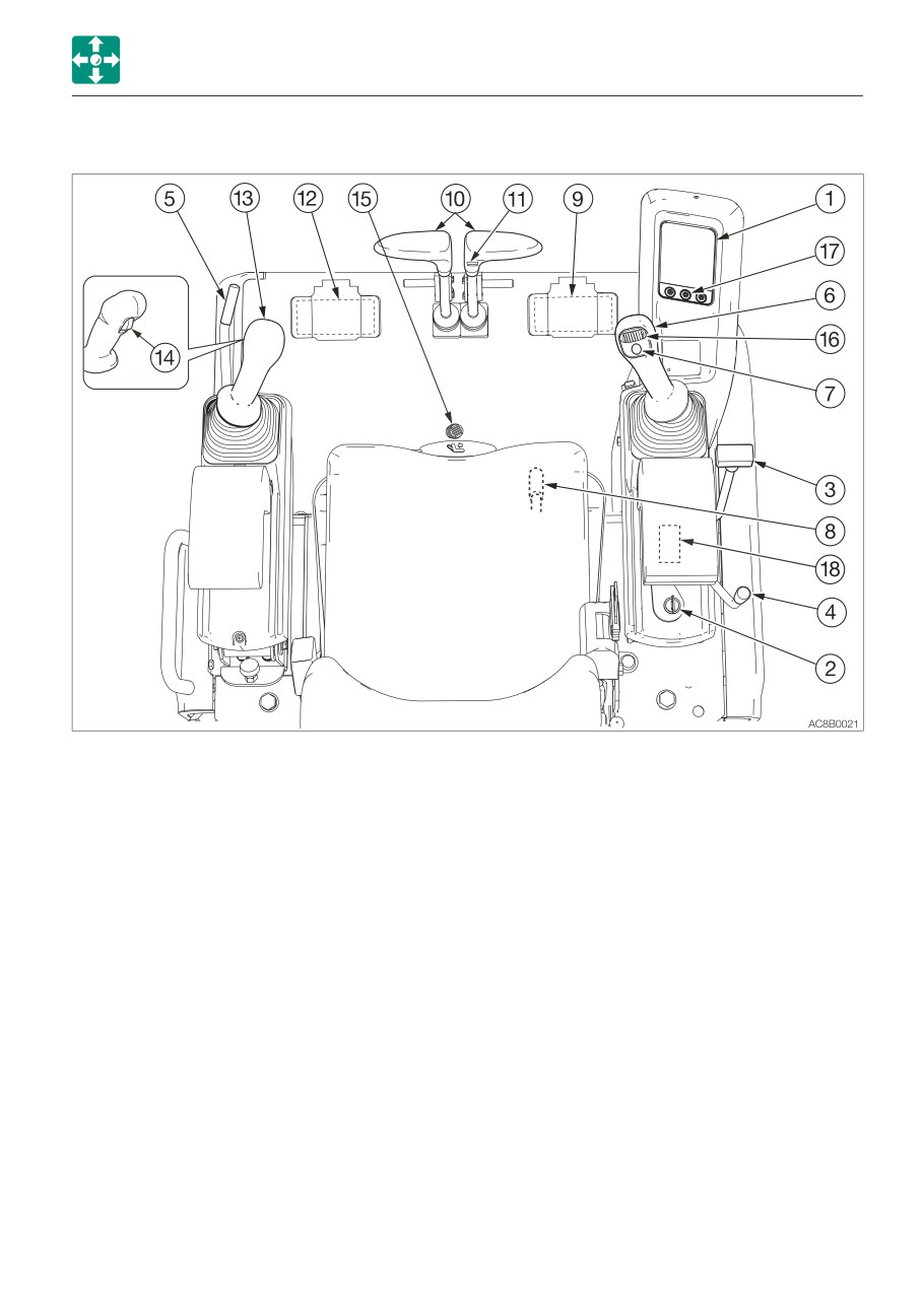
Controls
Names of components (Canopy)
1. Instrument cluster
10. Travel lever/Pedal
2. Starter switch
11. Travel speed switch
3. Blade lever
12. Auxiliary hydraulic pedal
4. Throttle lever
13. Left operating lever
5. Safety lock lever
14. Third auxiliary hydraulic botton*
6. Right operating lever
15. Third auxiliary hydraulic switch*
7. Horn button
16. Auxiliary 2nd switch*
8. Selector lever
17. Light switch
9. Boom swing pedal
18. Lift overload warning switch*
*: Subject to the specifications or optional products selected
2-5
Controls
Covers
Maintenance cover
Covers
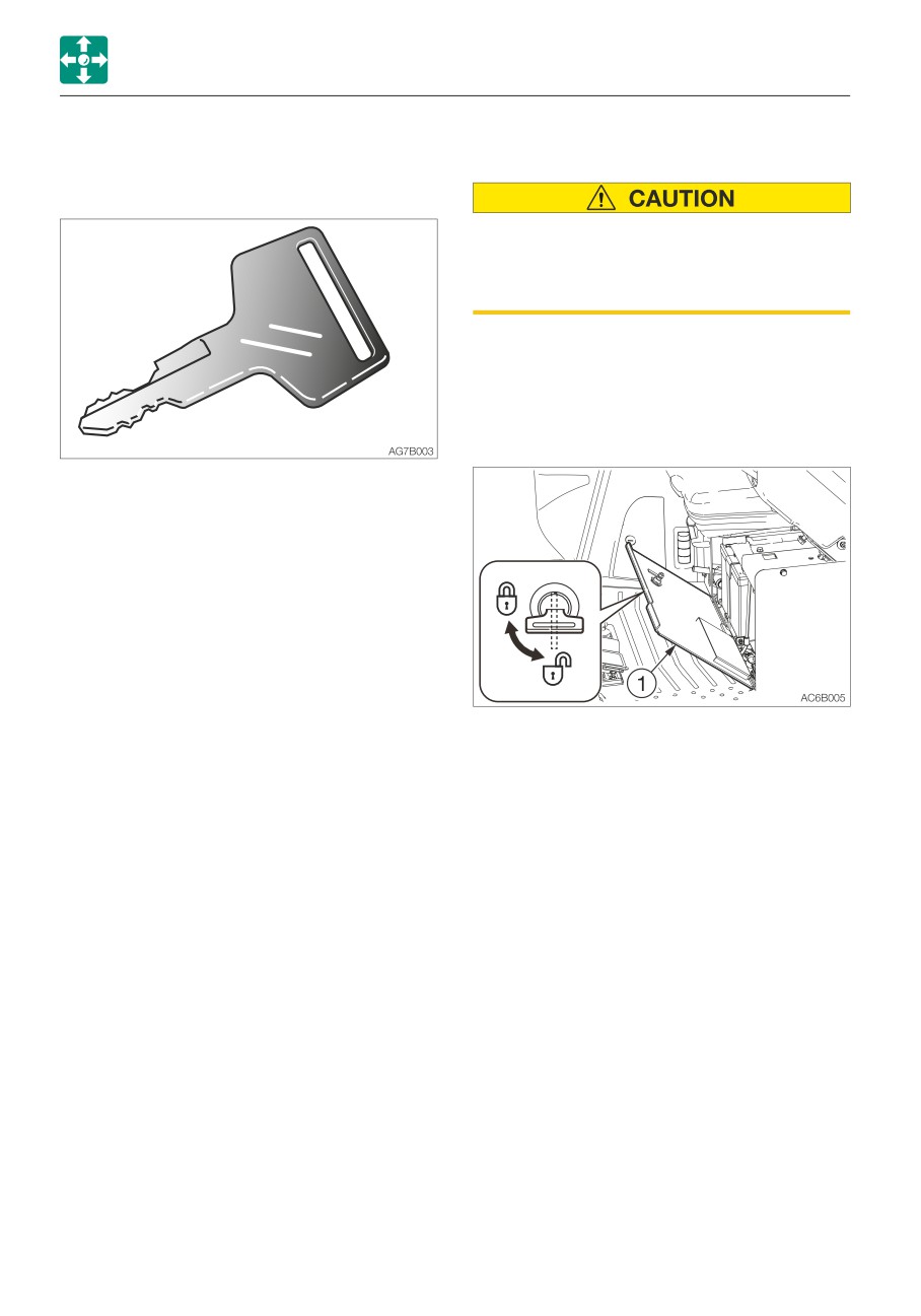
Starter key
When opening the maintenance cover,
make sure that the safety lock lever is in
the lock position and the engine is
stopped.
Open this cover to perform a maintenance
operation of the engine or to switch the
selector valve
Opening
The starter key is used to start and stop the
engine, as well as to lock and unlock the
following components:
• Fuel lid
• Manual storage compartment
• Engine hood
• Covers
1. Insert the starter key and turn it
counterclockwise to unlock the
maintenance cover (1).
Closing
1. Close the maintenance cover (1).
2. Insert the starter key and turn it clockwise
to lock the maintenance cover (1).
2-6
Controls
Covers
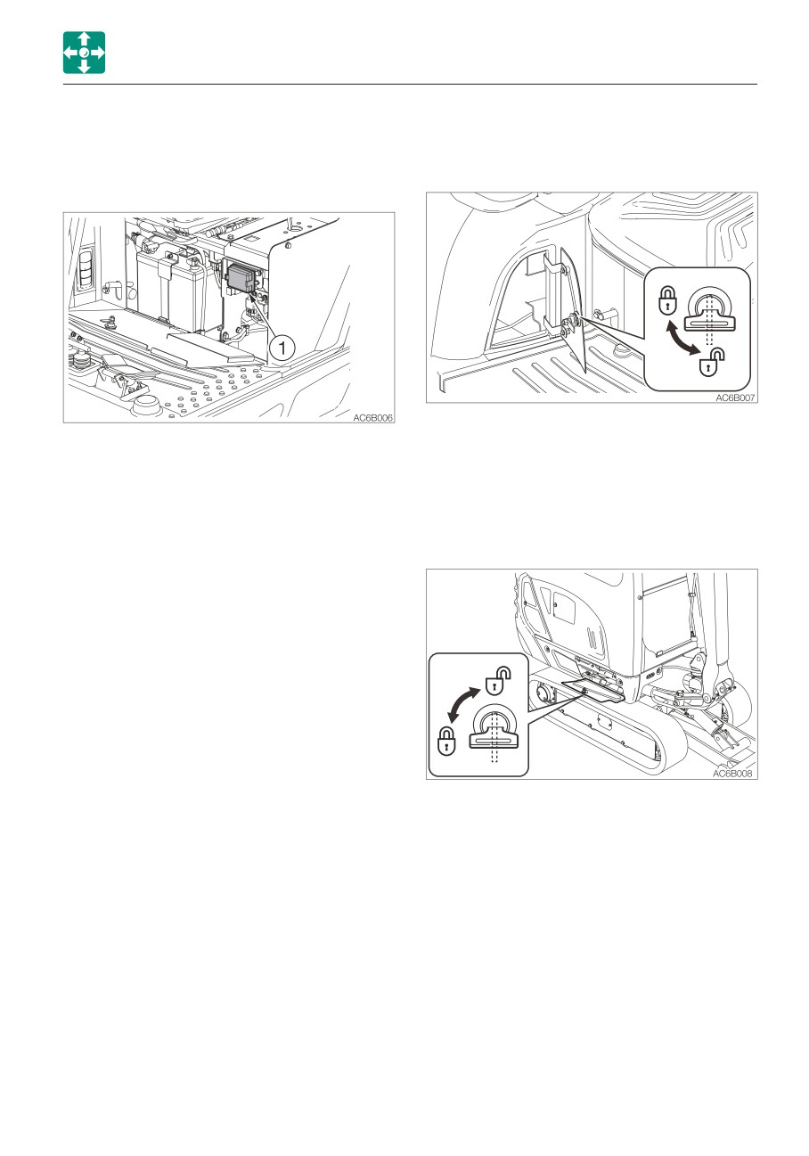
Fuse box
Tool case
This box is used to protect the electric
Opening
system from overcurrent.
1. To unlock this case, insert the starter key
and turn it counterclockwise.
Opening
1. Pull the fuse box cover (1) while pushing
the tab beside it.
Grease gun holder
Closing
Opening
1. Push in the fuse box cover (1) until the tab
clicks into place.
1. To unlock this holder, insert the starter key
and turn it counterclockwise.
2-7
Controls
Covers
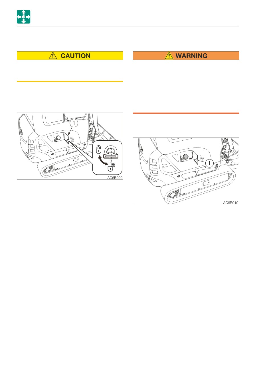
Fuel lid
Fuel filler port
When opening and closing the fuel lid, be
• Do not smoke and keep away from heat
careful not to get your hands caught by
or flame while filling the fuel tank.
the lid.
• Fill the fuel tank in a well ventilated
place, with the engine turned off.
For adding fuel, open this cover.
• Clean up spilled fuel immediately.
• Do not fill the fuel tank to capacity.
Opening
Allow room for oil expansion.
• Securely tighten the fuel filler cap.
Opening
1. Insert the starter key and turn it
counterclockwise to unlock the fuel lid (1).
Closing
1. Close the fuel lid (1).
1. Open the fuel lid.
2. Insert the starter key and turn it clockwise
2. Turn the fuel cap (1) counterclockwise and
to lock the fuel lid (1).
remove it.
Closing
1. Turn the fuel cap (1) it clockwise and close
it.
2. Close the fuel lid and lock it.
2-8
Controls
Covers
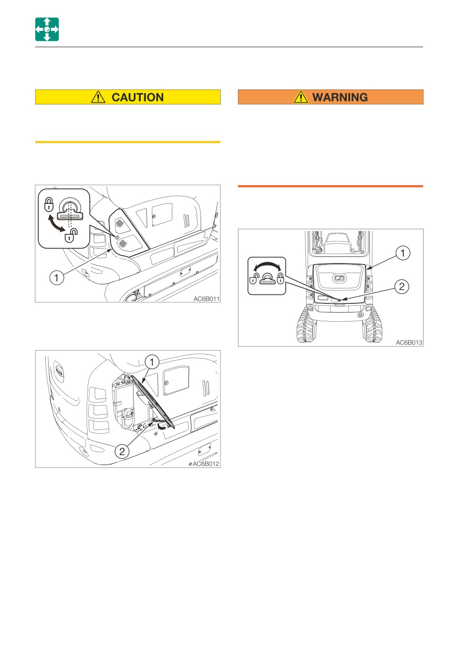
Side cover
Engine hood
When opening and closing the side cover,
• Before opening the engine hood, be
be careful not to get your hands or other
sure to stop the engine. If a hand or tool
parts of your body caught by the cover.
becomes trapped in the rotating or
moving part, serious injury could result.
• When opening or closing the engine
Opening
hood, be careful not to get your hands
or other parts of your body caught by it.
Opening
1. Insert the starter key and turn it
counterclockwise to unlock the side cover
(1).
1. Insert the starter key and turn it
counterclockwise to unlock the engine
hood (1).
2. Push in the key hole (2) with your thumb
and open the engine hood (1).
Closing
1. Close the engine hood (1) and press down
the edge of it until a click is heard.
2. Fully open the side cover (1) and secure it
with the stay (2)
Closing
1. Support the side cover (1) by hand and
release the stay (2).
2. Close the side cover (1).
3. Insert the starter key and turn it clockwise
to lock the side cover (1).
2-9
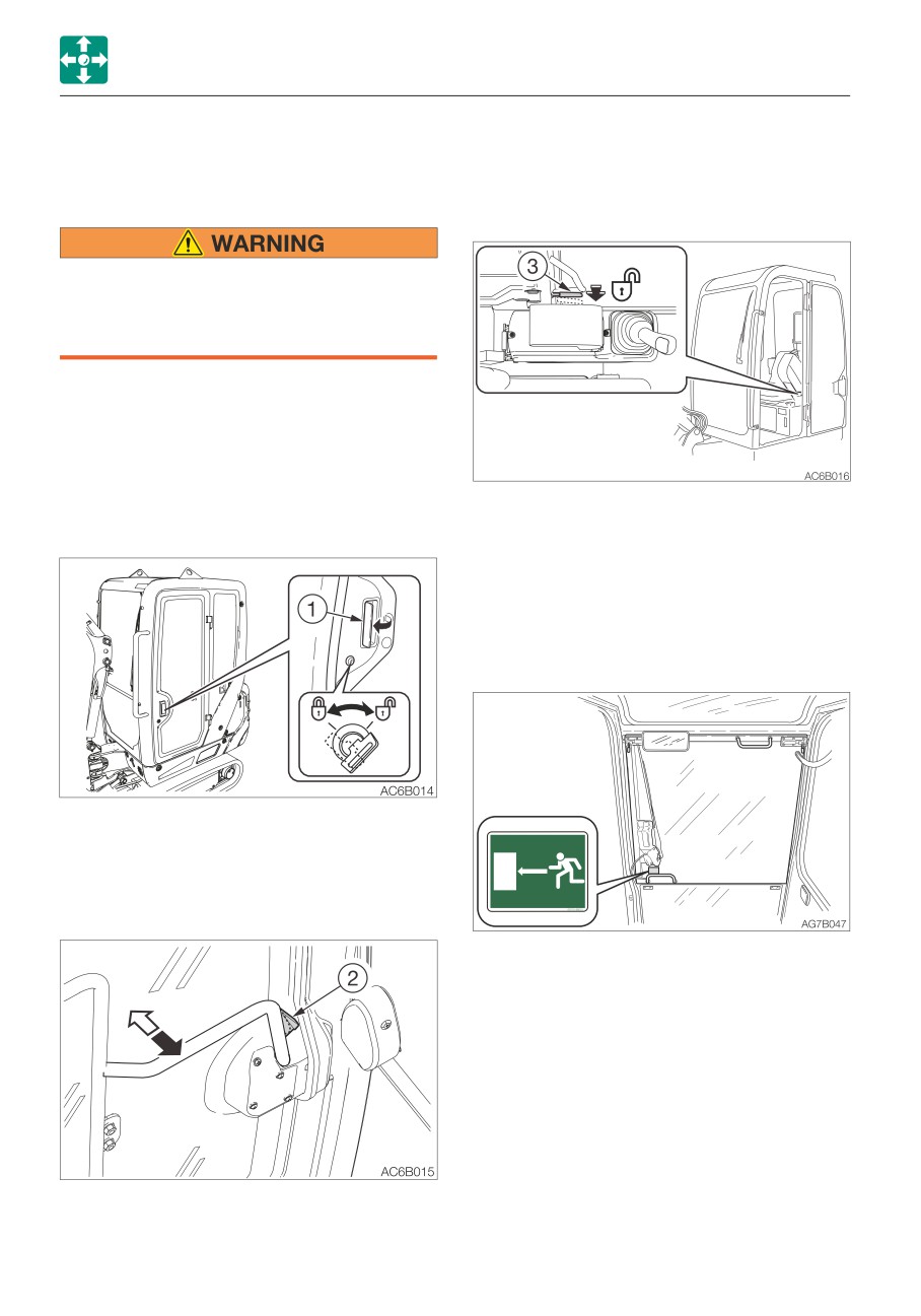
Controls
Cab
2. Open the door fully and press it against
Cab
the cab to secure it in place.
Cab door
Closing
When getting on or off the cab, first open
the door all the way until it is secured in
the catch and check that it does not
move.
Open the door fully and press it against the
catch at the back of the door to secure it in
place.
The door must be locked when getting on or
off the machine and while in operation.
1. Push the release lever (3) to the lower.
Locking and unlocking
2. Close the released door.
Emergency exit
Front window (excluding machines with a
front guard)
Insert the starter key and turn it.
Opening
1. Pull the knob (1) towards you and open
the door.
If you should become trapped inside the
cab, open the front window to get out.
To open the door from inside the cab, hold
the door opener (2).
2-10
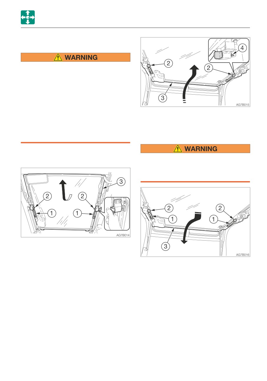
Controls
Cab
Front window
• Grasp the handles firmly with both
hands when opening and closing the
front window. Your head or hands may
get caught if it slips from your hands.
• When the front window is opened or
closed, it will come close to the head.
Be careful that the window does not
strike the head.
5. Release your thumb from the knobs (2)
• When you open the front window, be
and then lift the front window (3) fully and
sure to lock it in place with the lock pins
lock the front window with lock pin (4).
on the left and right sides. The window
may fall if it is not locked in place.
Closing
Opening
When closing the front window slowly so
as not to hit your head. Lowering the
window abruptly may result injury or
damage the front window.
1. Park on a level surface and stop the
engine.
2. Set the safety lock lever to the locked
position.
1. Grasp the left and right handles (1) and
3. Grasp the left and right handles (1) and
press the knobs (2) with your thumb to
press the knobs (2) with your thumb to
release the lock.
release the lock.
2. Pull down the front window (3) and while
4. Pull the front window (3) toward you and
doing so, slide it to the front and slowly
lift while doing so.
lower it.
2-11
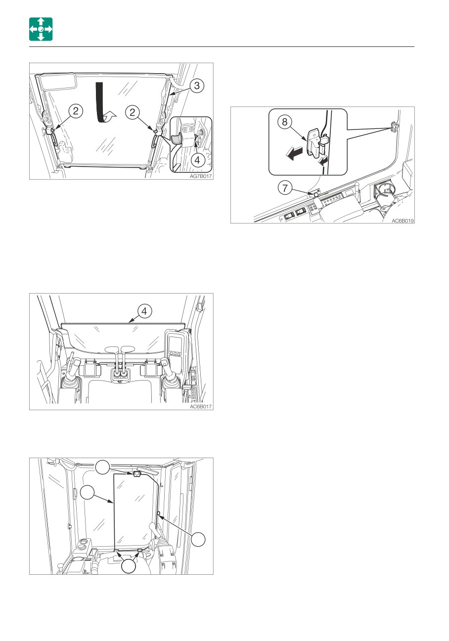
Controls
Cab
Side window
Opening
3. Release your thumb from the knobs (2)
and then press the front window toward
front and lock the front window with lock
pin (4).
1. Release the lock by turning the locking
screw (7) counterclockwise
Lower front window
2. Hold the catch (8) to disengage it and
open the side window.
Removing
3. Secure the side window by turning the
locking screw (7) clockwise.
Closing
1. Release the lock by turning the locking
screw (7) counterclockwise
2. Close the window until a click is heard,
and then secure the window by turning
the lock screw (7) clockwise.
1. Open the front window and stow it in the
ceiling.
2. Slowly lift the lower front window (4).
6
4
5
5
AG7B019
3. Hold the glass firmly, place it through the
guides (5) at the rear, and then set it on
the supports (6) to fasten it in place.
2-12
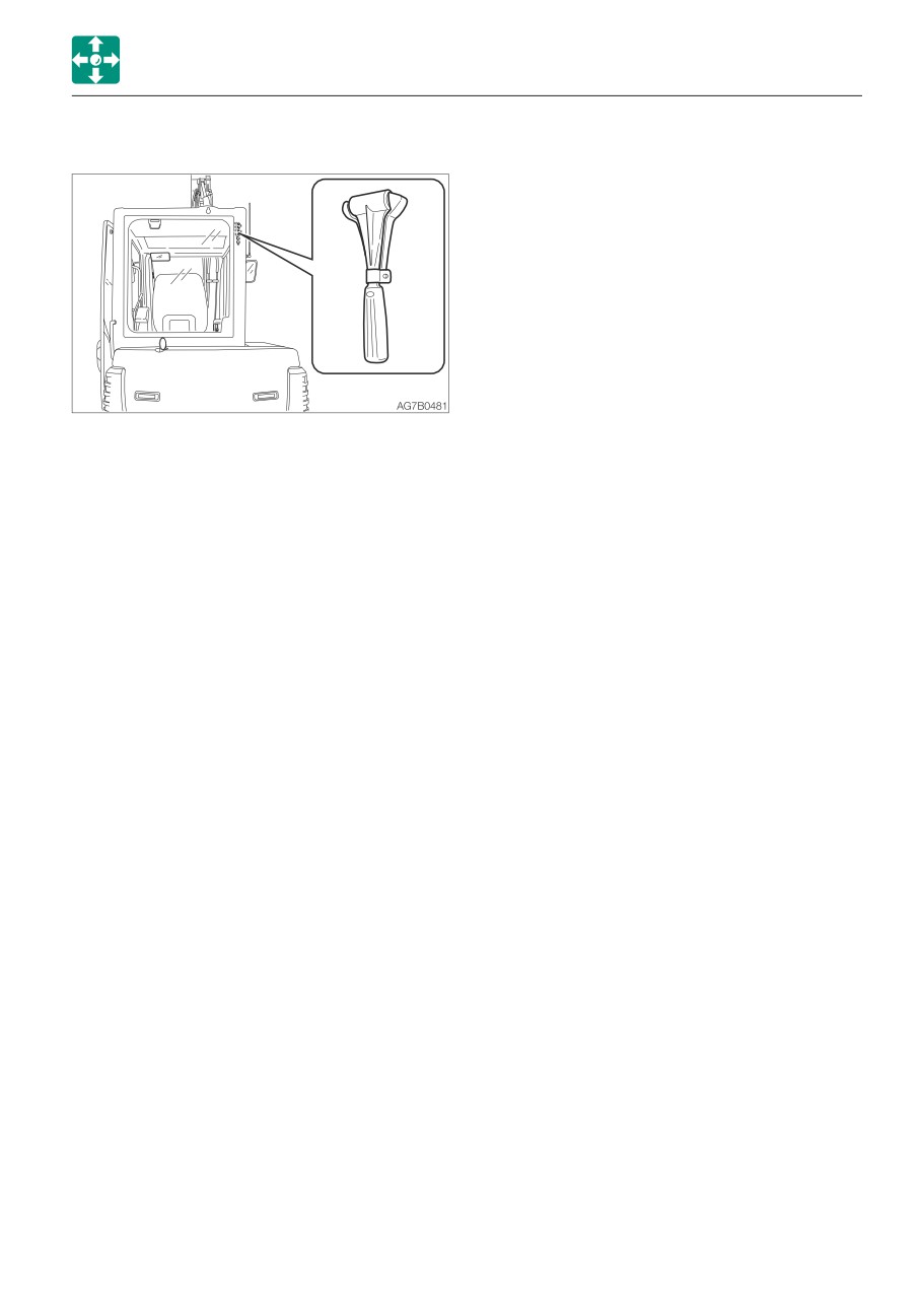
Controls
Cab
Emergency hammer (optional)
An emergency hammer is installed to be
used to escape from the cab in an
emergency. When escaping, break the
windows with the hammer.
• When breaking the windowpane with a
hammer, take great care not to injure
yourself with the broken glass pieces.
• Remove the glass pieces from the window
sill so as not to cut yourself when
evacuating. Broken glass will fall from the
window, so be careful of your footing and
do not slip on the glass.
2-13
Controls
Seat and seat belt
Seat and seat belt
Seat (If equipped)
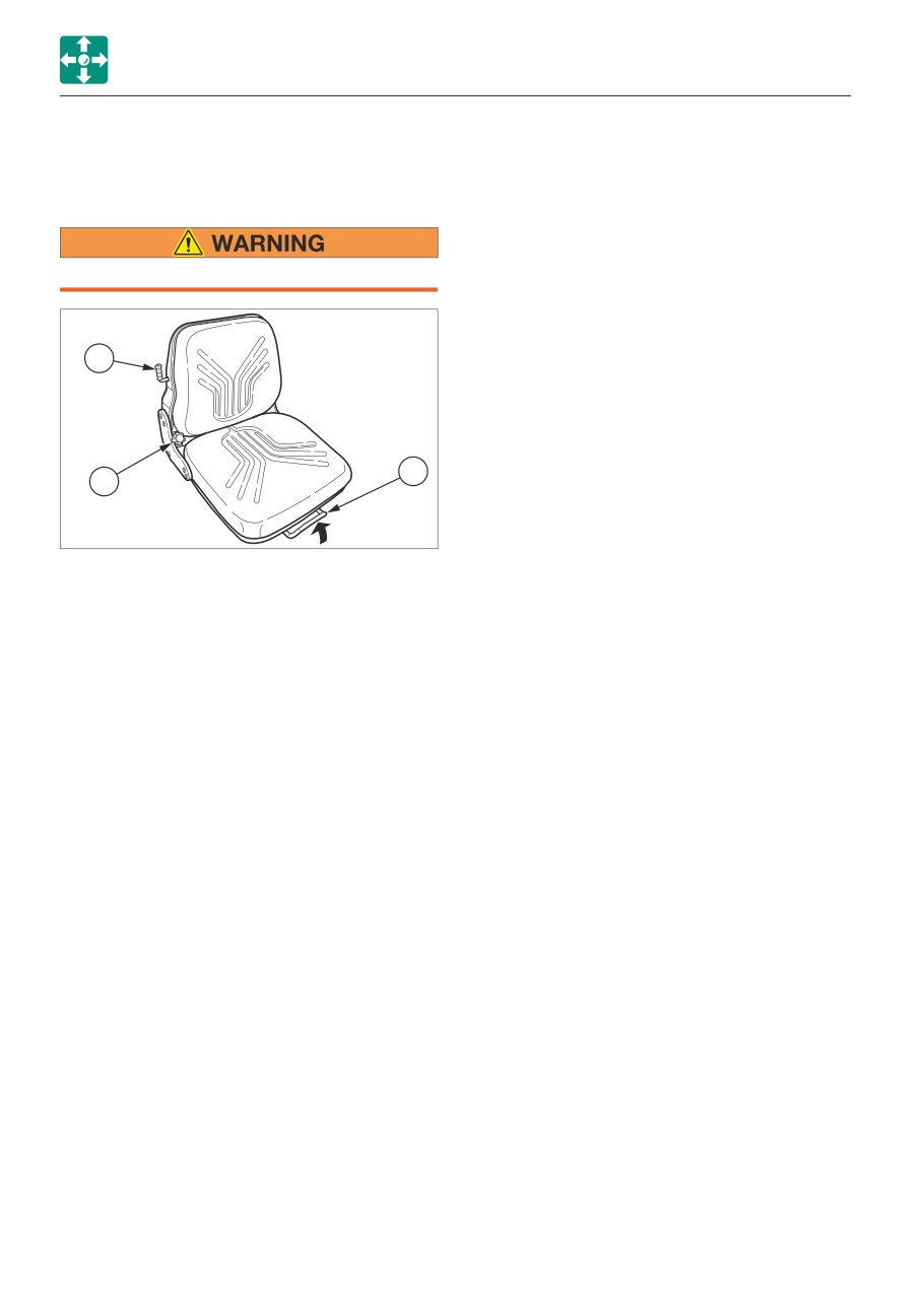
Adjust and secure the seat.
3
2
1
AD6B017
(A) Adjusting the backrest angle
1. Sit up and sit back in the seat.
2. Set the backrest to the desired angle by
turning the handle (1).
(B) Fore-and-aft adjustment
1. Pull up the lever (2) and slide the seat
backward or forward to the desired
position for operation of machine.
2. Release the lever (2) at the desired
position to secure the seat.
Adjustment range: 10 positions, in 150
mm (5.9 in.)
(C) Adjusting according to operator’s
weight
1. Move the lever (3) to set it according to
the weight of operator.
Position of the lever (3)
Upper
Light weight operator
Middle
Medium weight operator
Lower
Heavy weight operator
2-14
Controls
Seat and seat belt
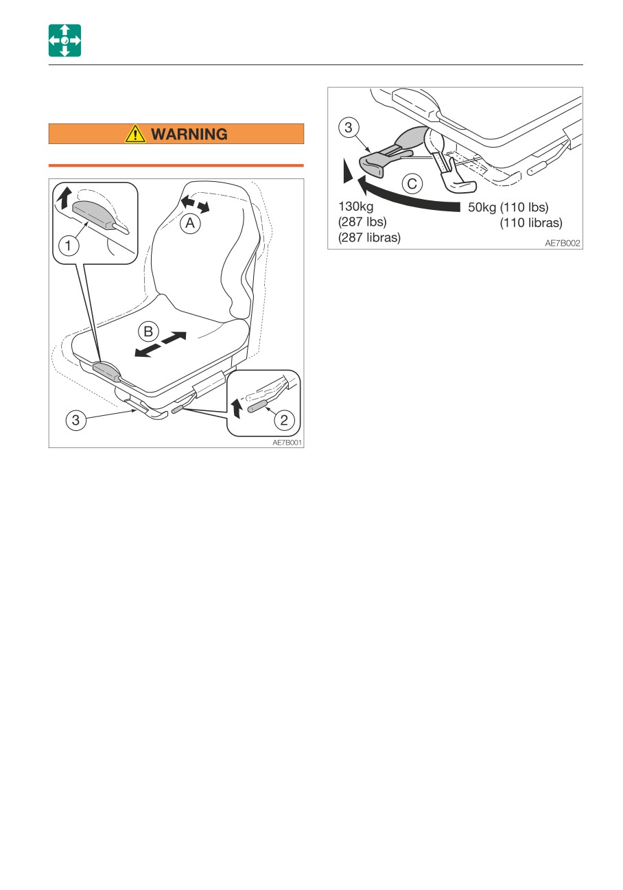
High-back seat (If equipped)
Adjust and secure the seat.
(C) Adjusting according to operator’s
weight
1. Turn the handle (3) until the display
indicates the weight of operator.
Adjustment range: 50 to 130 kg (110 to
287 lbs)
2. When adjusting for a weight lower than
the currently set weight, first turn the
handle (3) as far as it goes to cancel the
setting, then readjust.
(A) Adjusting the backrest
1. Sit up and sit back in the seat.
2. Pull up the lever (1), recline the backrest
by using the spring force. Release the
lever (1) at the desired angle to secure the
backrest.
(B) Fore-and-aft adjustment
1. Pull up the lever (2) and slide the seat
backward or forward to the desired
position for operation of machine.
2. Release the lever (2) at the desired
position to secure the seat.
Adjustment range: 10 positions, in 150mm
(5.9in.)
2-15
Controls
Seat and seat belt
Seat belt
Releasing the seat belt
Be sure to fasten the seat belt securely
before starting the engine.
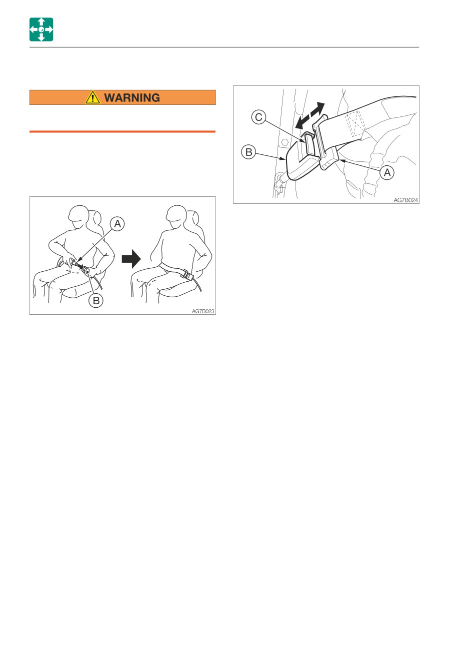
Fastening the seat belt
1. Adjust the seat to the desired position for
operation, sit up and sit back in the seat.
2. Pull the seat belt to the desired length.
1. Grasp the tongue plate (A) and press the
button (C) on the buckle (B).
The seat belt retracts back into its original
position.
3. Make sure that the belt is not twisted and
then insert the tongue plate (A) into the
buckle (B) of the seat belt until you hear a
clicking sound as it locks in place.
4. Check if the belt is securely locked by
pulling it, and arrange the belt around your
waist.
2-16
Memo
2-17
Controls
Instrument cluster
Instrument cluster
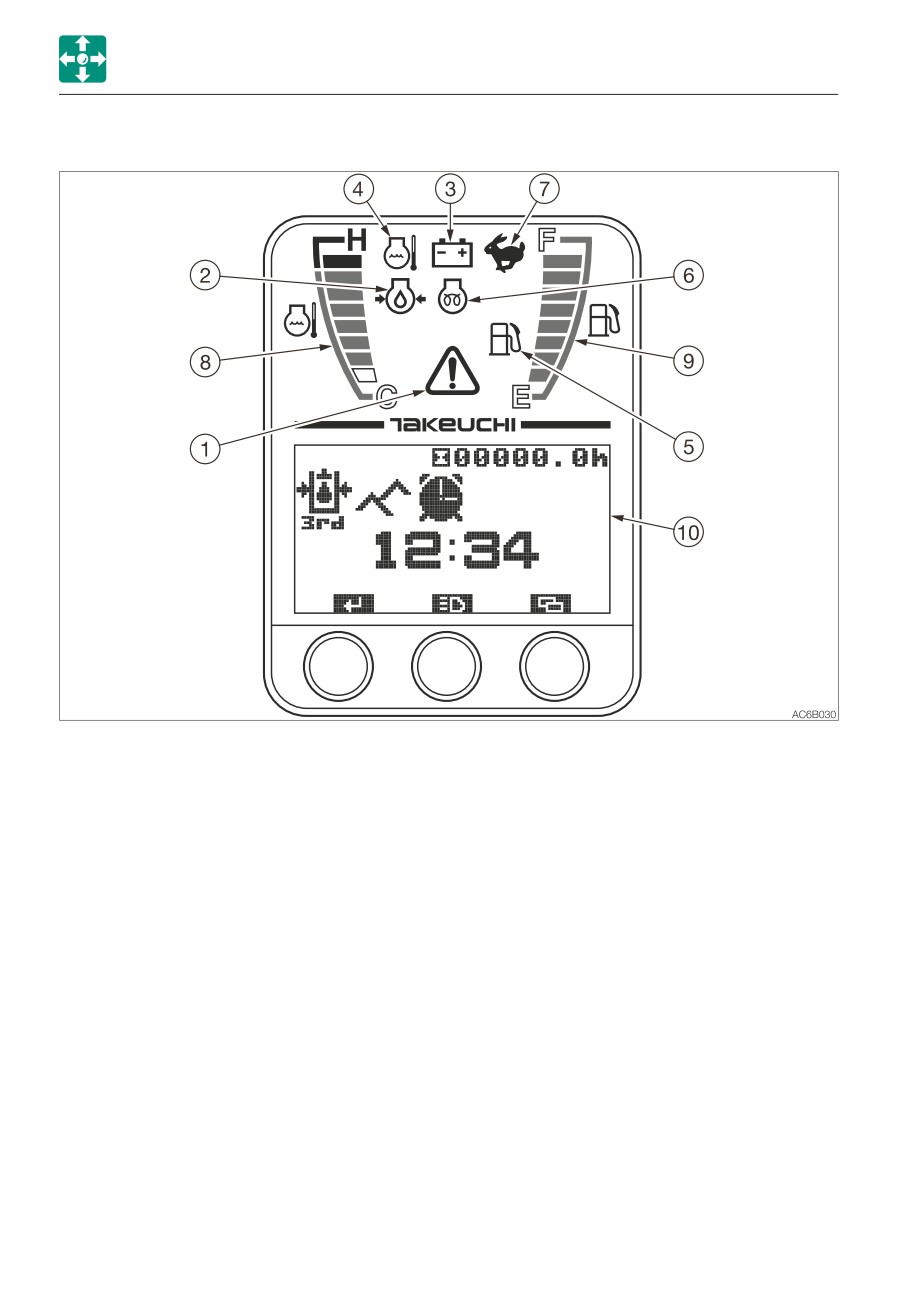
Once the starter switch is turned to ON, all lamps on the instrument cluster light up.
Then, the battery charge warning lamp (3) and the engine emergency lamp (1) start flashing.
The machine system is normal if the lamps turn off after the engine is started.
If any lamp is not lit when the starter switch is turned to ON, there is something wrong in the
machine. Consult your sales or service dealer.
Warning lamps
2. Engine oil pressure warning lamp
This lamp flashes and an alarm is sounded
IMPORTANT: If a warning lamp flashes
if the lubricant oil pressure abnormally low
and an alarm is sounded, immediately
while the engine is running.
stop all operations and check the
corresponding component.
3. Battery charge warning lamp
Refer to “If a warning lamp flashes” on
This lamp flashes and an alarm is sounded
page 6-9.
if a problem rises in the charging system
while the engine is running.
1. Engine emergency lamp
This lamp flashes and an alarm sounds if
4. Coolant temperature warning lamp
there is a problem with the engine or
This lamp flashes and an alarm is sounded
charging system.
if the engine coolant temperature
becomes abnormally high while the engine
is running.
2-18
Controls
Instrument cluster
5. Fuel level warning lamp
Meters
This lamp turns on if the fuel level
becomes low while the starter switch is in
8. Water temperature gauge
the ON position.
Indicates the temperature of the engine
coolant water.
The LED should be within the green range
Indicators
during machine operation.
The red range indicates overheating.
6. Glow lamp
This lamp goes out when the engine
9. Fuel Gauge
preheating is completed.
Indicates the amount of fuel in the tank.
Be sure to top off the tank before running
7. Travel speed lamp
out of fuel.
This lamp turns on when the travel speed
button is set to the 2nd (high) speed.
2-19
Controls
Instrument cluster
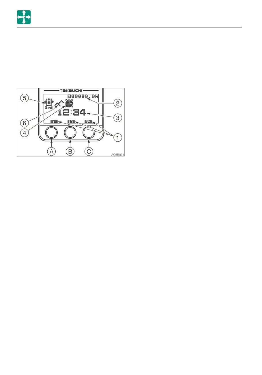
Multi-data display
4. Alarm indicator lamp
The clock symbol appears when the
10. LCD (liquid crystal display)
alarm function is turned on.
It displays various data on hour meter,
Refer to “Alarm setting” on page 2-24.
trip meter and the machine.
5. Auxiliary 3rd hydraulic pressure
Home screen
warning lamp (If equipped)
This lamp lights up and an alarm
sounds if the fixed side (left “e”)
pressure of the auxiliary 3rd drops
abnormally while the engine is running
or if the quick-hitch is being removed
or installed.
6. Highland mode indicator lamp
(If equipped)
When the highland mode is selected
This mode is used to reduce the
engine load due to the hydraulic pump.
1. Key function display
When the machine is operated at a
The key function display changes
high-altitude site, the engine output is
depending on the screens (Home,
decreased due to thin air. In such
Menu and each setting)
cases, the hydraulic horse power is
For actual operation, use the buttons,
automatically adjusted to prevent the
“A”, “B” and “C”, located beneath
engine from stalling. The machine
each symbol. Refer to “Operating
automatically enters this mode if the
each key” on pages 2-20 to 2-25.
altitude detected by the bolometric
sensor is 800 m (2622 ft) or more.
2. Hour meter/Trip meter
• Hour meter
7. Lift overload warning indicator lamp
Displays the total engine running time
This lamp turns on when the lift
in hours.
overload warning switch is turned on.
The rightmost digit indicates tenths of
hours (6 minutes).
Set the inspection and maintenance
intervals according to the time
displayed on the hour meter.
• Trip meter
Three patterns of desired operating
hours can be displayed.
Refer to “Trip meter display” on page
2-21.
3. Time display
Displays the time set.
Refer to “Time setting” on page 2-24.
2-20
Controls
Instrument cluster
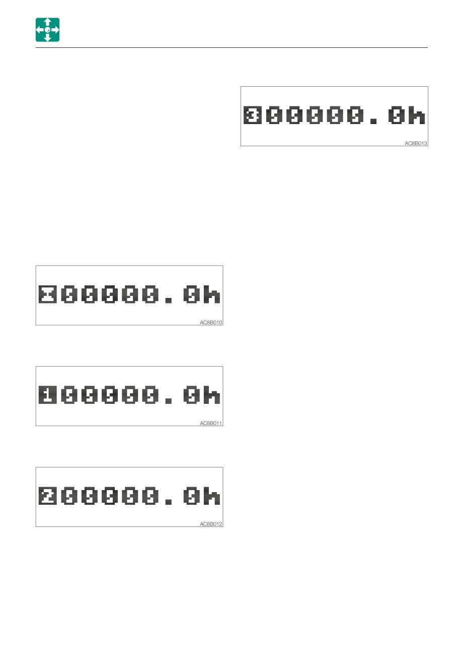
Function of each key
4. Trip meter 3
The functions are as below in the Home
screen. The different functions appear in the
other screens.
A. Stopping alarm
Pressing the (A) key stops alarm.
5. Returns to the hour meter
B. Work light/meter switching
· Pressing the (B) key turns on or off the
C.Menu/trip meter reset
work light.
· Pressing the (C) key switches to the
· Pressing and holding the (B) key for two
Menu screen.
seconds or more each time the display
· Pressing and holding the (C) key for
changes as follows:
three seconds or more while the trip
meter is displayed returns the trip meter
1. Hour meter
to “0”.
2. Trip meter 1
3. Trip meter 2
2-21
Controls
Instrument cluster
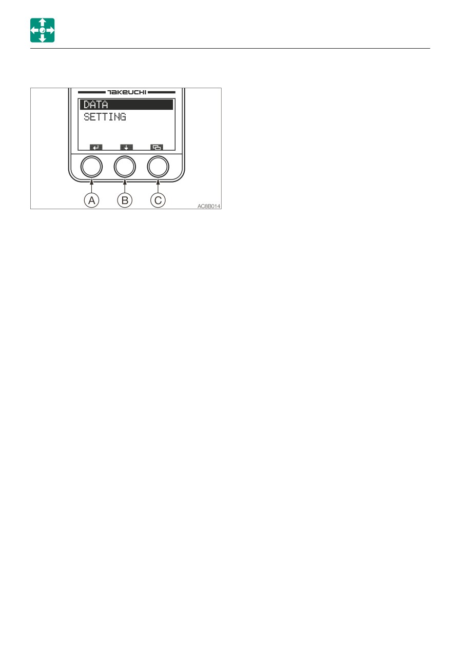
Menu screen
Press the (A) key to proceed to the screen
selected by the bar.
Press the (B) key to move the selection bar.
Press the (C) key to return to the Home
screen.
• DATA
Shows the coolant temperature and the
trip meter for inspection and
maintenance.
Unlike the trip meter displayed on the
Home screen, data items on the engine
oil, hydraulic oil and coolant are included
so that you can use them as a guideline
for replacement.
• SETTING
Time, alarm and contrast can be set.
2-22
Controls
Instrument cluster
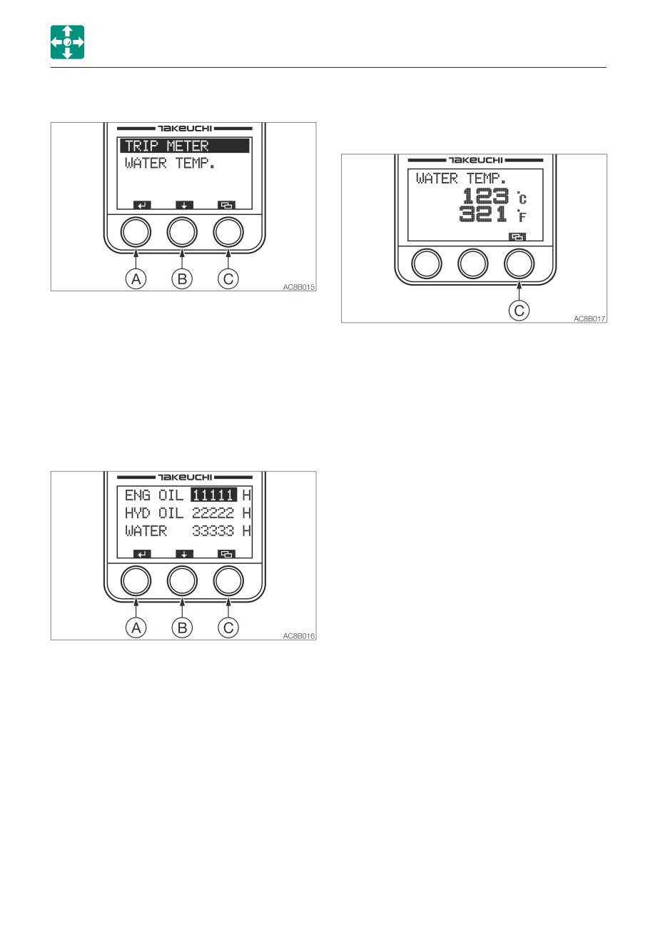
Data screen (DATA)
• Coolant temperature (WATER TEMP)
Displays the coolant temperature in
Celsius °C or Fahrenheit °F.
Press the (A) key to proceed to the screen
selected by the bar.
Press the (B) key to move the selection bar.
Press the (C) key to return to the Data
Press the (C) key to return to the Menu
screen.
screen.
• Trip meter (TRIP METER) for
maintenance
The trip meters for the engine oil,
hydraulic oil or coolant are displayed.
Press and hold the (A) key for at least five
seconds resets the selected trip meter to
“0”.
Press the (B) key to move the selection
bar.
Press the (C) key to return to the DATA
screen.
2-23
Controls
Instrument cluster
Setting selection screen (SETTING)
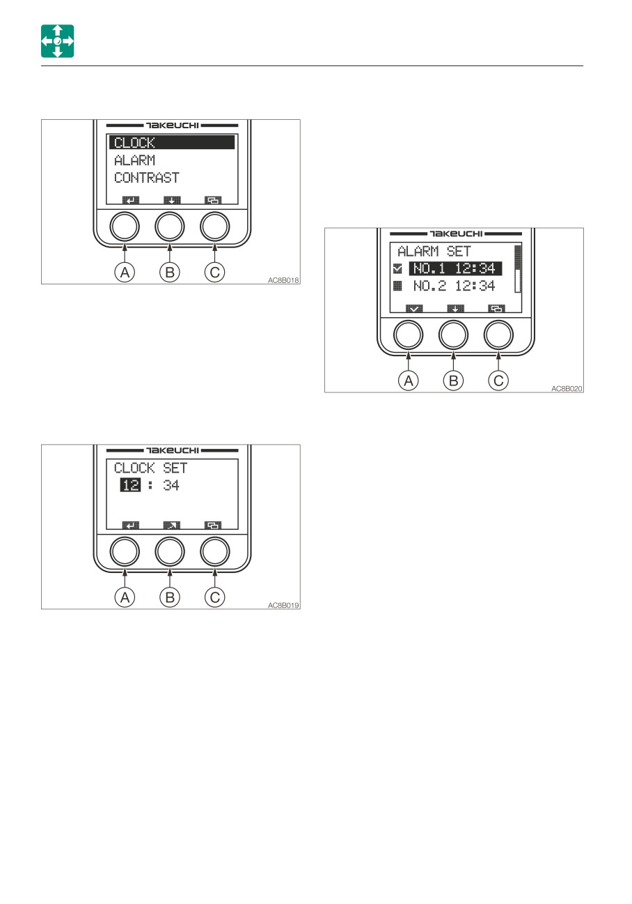
e. Press the (C) key cancels editing and to
return to the Setting Selection screen.
• Alarm setting (ALARM)
Five patterns of alarm setting are
available.
Alarm function can be set to on or off
within the five patterns.
Press the (A) key to proceed to the screen
selected by the bar.
Press the key (B) to move the selection bar.
Press the (C) key to return to the Menu
screen.
• Time setting (CLOCK)
The time to be displayed on the Home
a. When the selection bar is at ALARM,
screen can be set here.
press the (A) key to proceed to the alarm
setting screen (ALARM SET).
b. Press the (A) key in this screen to place
a checkmark in the box at the left of the
setting bar. Press the (A) key again to
remove the checkmark.
The alarm setting cannot be changed
only by placing or removing a
checkmark.
c. Press and hold the (A) key for at least
two seconds to complete the setting
and to return to the Setting Selection
screen.
a. When the selection bar is at CLOCK,
Be sure to perform the above operation
press the (A) key to proceed to the time
when you wish to set the alarm.
setting screen (CLOCK SET).
A clock symbol is displayed on the
b. Pressing the (A) key in this screen moves
Home screen.
the selection bar and flashes the figures
d. Press the (B) key to move the selection
on the bar.
bar.
Setting range: hours, 1 to 24; minutes,
e. Press and hold the (B) key for at least
00 to 59
three seconds to enter the alarm time
c. Press the (B) key to increase the number
setting mode.
value selected.
f. Press the (C) key to cancel editing and
Press and hold the (B) key to rapidly
to return to the Setting Selection screen.
increase the number value selected.
Checked
On
d. Press and hold the (A) key for at least
Unchecked
Off
two seconds to complete the setting
and to return to the Setting Selection
screen.
2-24
Controls
Instrument cluster
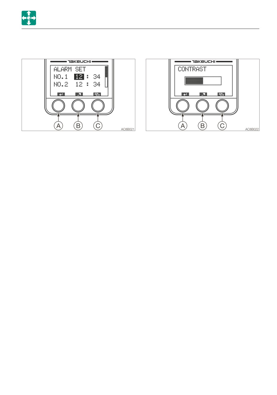
• Alarm time setting mode
• Contrast setting (CONTRAST)
Sets the time for alarm.
Adjust the LCD contrast.
a. Select the item to be set in the alarm
a. When the selection bar is at CONTRAST,
setting screen (ALARM SET).
press the (A) key to proceed to the
b. Press and hold the (B) key for at least
contrast setting screen (CONTRAST).
three seconds to enter the alarm time
b. To increase contrast, press the (B) key.
setting mode.
The bar advances to the right.
c. Press the (A) key in this screen to move
Press and hold the (B) key to rapidly
the selection bar and to flash the figures
advance the bar.
on the bar.
Once the bar reaches the right end
Setting range: hours, 1 to 24; minutes,
(highest contrast), it returns to the left
00 to 59
end (lowest contrast).
d. Press the (B) key to increase the number
c. Press and hold the (A) key for at least
value selected.
three seconds to complete the setting
Press and hold the (B) key to rapidly
and to return to the Setting Selection
increase the number value selected.
screen.
e. Press and hold the (A) key for at least
d. Press the (C) key to cancel editing and
two seconds to complete the setting
to return to the Setting Selection screen.
and to return to the Setting Selection
The changes made to the setting are
screen.
reflected, but they will be removed when
f. Press the (C) key to cancel editing and
the starter switch is turned off.
to return to the Setting Selection screen.
2-25
Controls
Switches
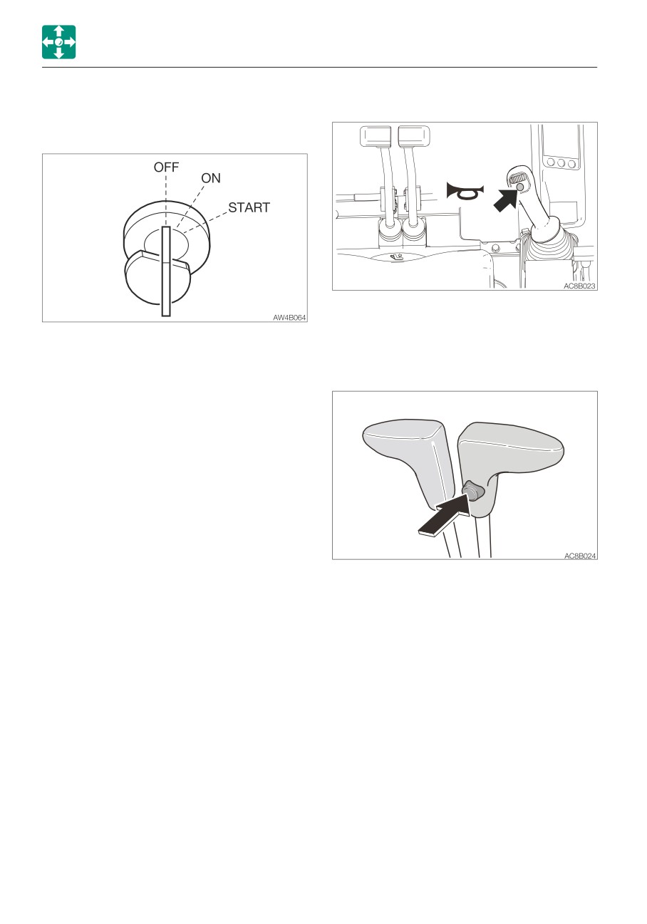
Horn button
Switches
Starter switch
Press the button situated on the right
operating lever to blow the horn.
IMPORTANT: Do not repeatedly switch
the key from OFF to ON and ON to OFF
over a short period. Doing so will cause
Travel speed switch
engine breakdown.
OFF
Position for stopping the engine
and inserting or removing the key.
ON
Position in which the engine is
running. At this position, all the
electrical equipment is functional.
When the coolant temperature is
too low, the engine is
automatically preheated.
START Position for starting the engine.
When the key is released, the
switch automatically returns to the
Press this switch to set the travel speed to
ON position.
2nd (high) speed. Press it again to return to
1st (low) speed.
2-26
Controls
Switches
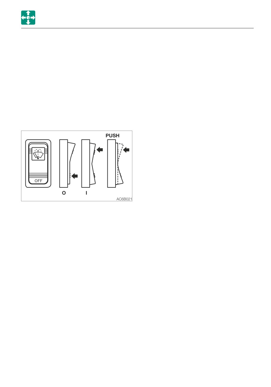
Wiper switch
Second auxiliary hydraulic
switch
IMPORTANT: If no washer fluid is
discharged, do not operate the washer.
Refer to “Second auxiliary hydraulic switch”
Doing so may damage the pump.
on page 2-44.
IMPORTANT: Operating the wiper with no
moisture on the windshield will scratch
the glass. Use water or washer fluid when
Third auxiliary hydraulic switch
operating the wiper.
and button
IMPORTANT: In cold climates, the wiper
blade may freeze to the glass. Operating
Refer to “Third auxiliary hydraulic switch and
the wiper forcibly may damage the wiper
button” on page 2-44.
motor.
O
Off
I
Wiper operates
PUSH Sprays washer fluid when
pressed. Stops when released.
2-27
Controls
Switches
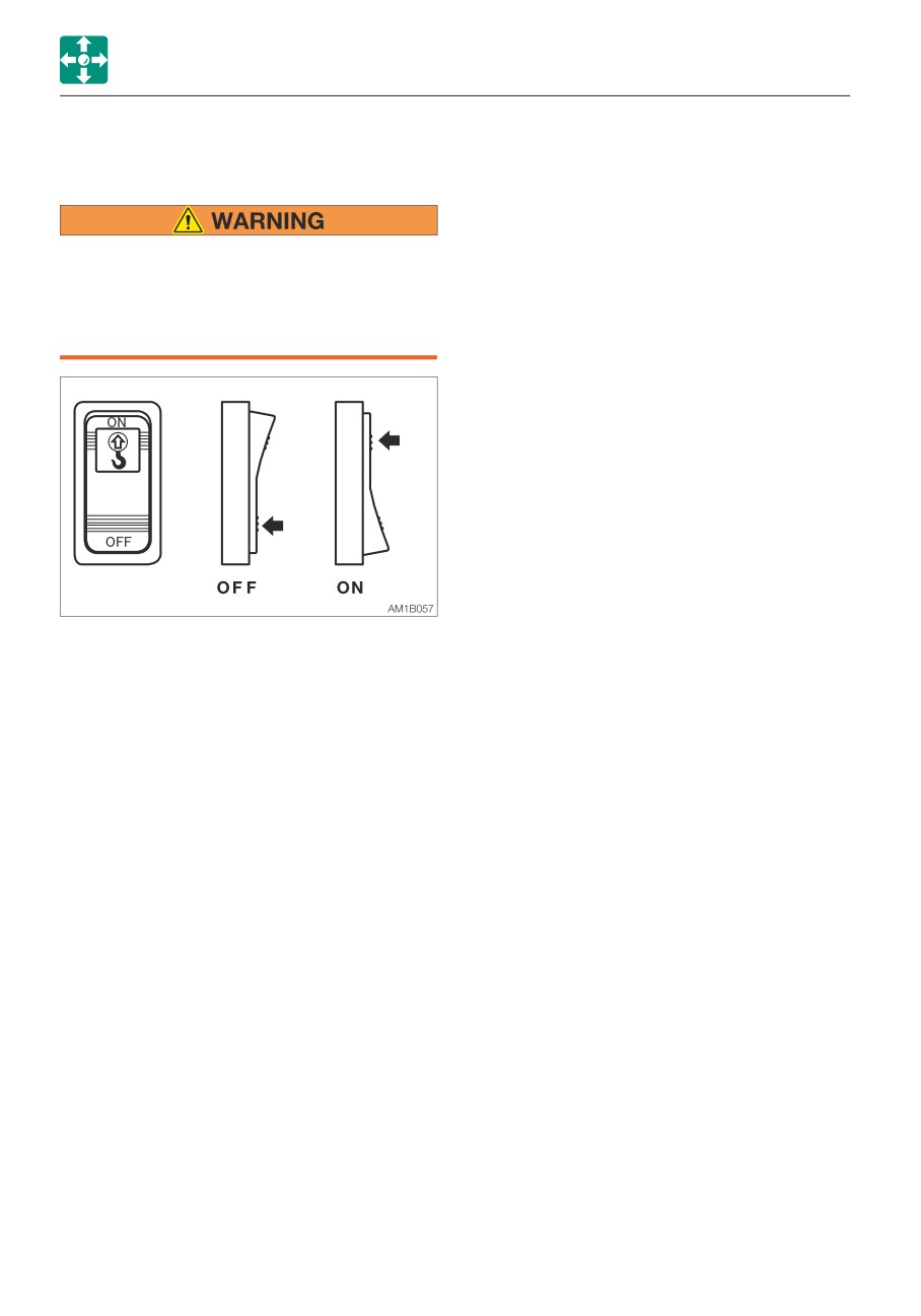
Overload warning switch
(If equipped)
If the overload is not removed after the
overload warning horn is sounded, the
machine may tip over. If the horn starts
sounding, stop operating the machine
and lighten the load.
If a weight greater than the lifting capacity is
applied or lifted, the overload warning device
is activated and the horn sounds. (When the
overload warning switch is turned on.)
OFF
Off
ON
On
2-28
Controls
Levers and Pedals
Throttle lever
Levers and Pedals
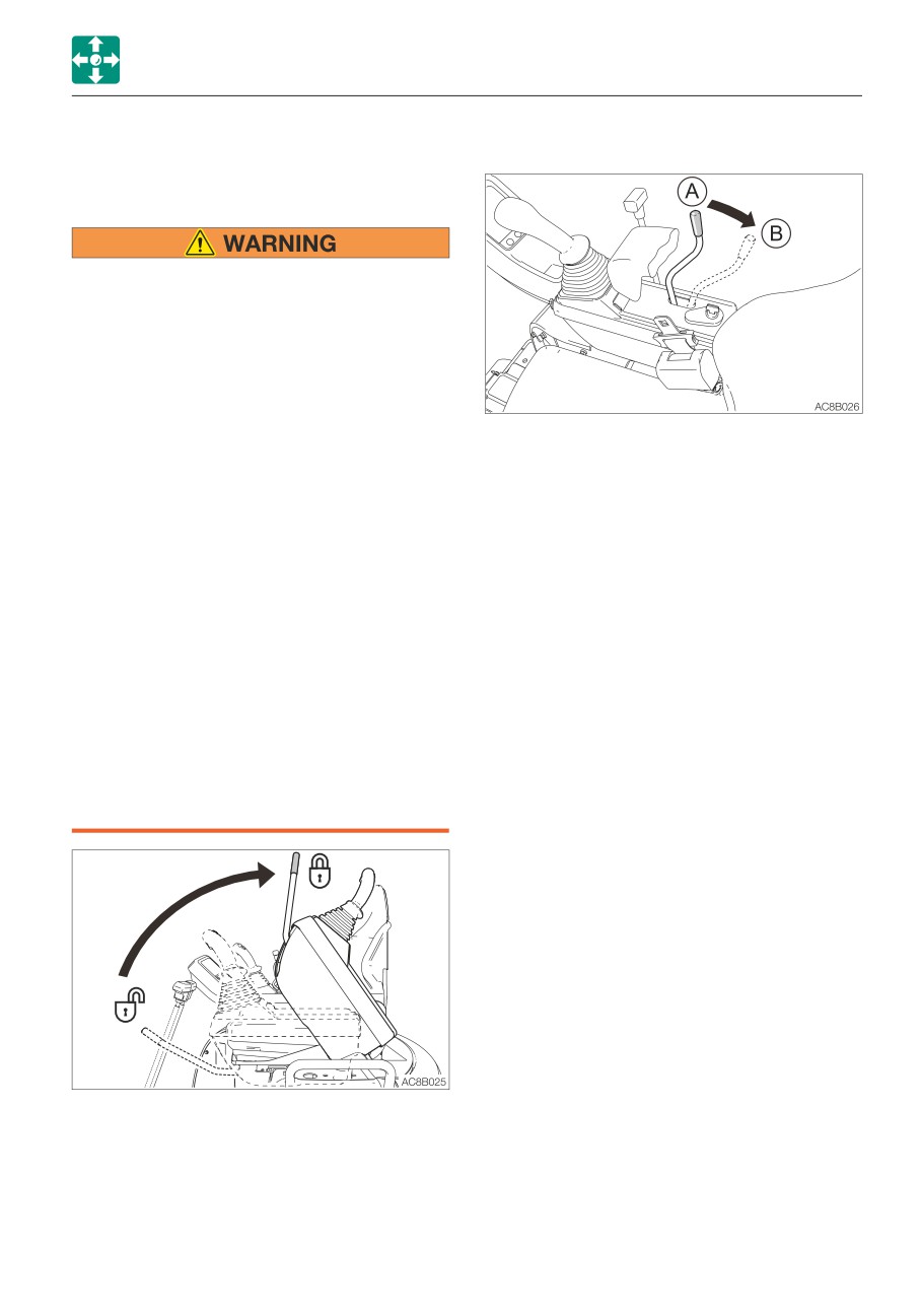
Safety lock lever
• Before standing up from the operator’s
seat to, for example, adjust the
operator’s seat, lower the working
equipment to the ground, raise the
safety lock levers to engage the lock
and stop the engine. If any controls
should be accidentally touched when
the safety lock levers is lowered
This controls the engine speed.
(unlocked), the machine will suddenly
(A)
Low idling
move and cause serious injury or death.
(B)
Maximum speed
• Note that the dozer blade, boom swing
and auxiliary hydraulic controls cannot
be locked, even when the safety lock
lever is set to the locked position.
Do not carelessly touch these controls.
• Be careful not to touch the operating
levers when raising or lowering the
safety lock lever.
• Before leaving the operator’s seat, lower
the working equipment to the ground,
raise the safety lock levers to engage
the lock and stop the engine. Also, be
sure to remove the key, lock the door
and covers, take it with you and store it
in a specified place.
This device is for locking the hoe attachment,
slewing and traveling.
When the lever is raised, the lever stand
springs up and the controls are locked.
2-29
Controls
Levers and Pedals
Operating levers
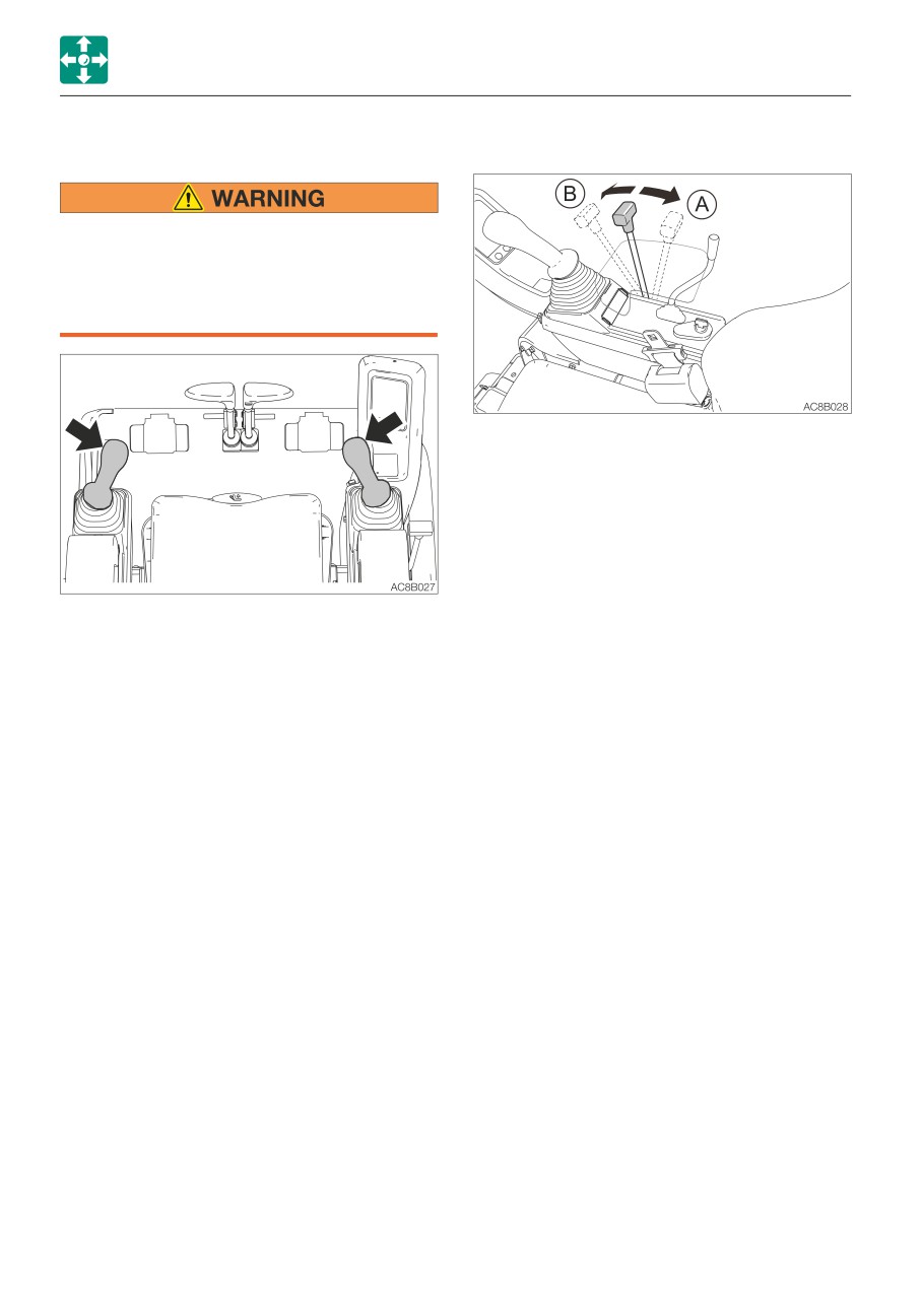
Blade lever
• Before starting operation, carefully
check which lever pattern you are going
to use.
• It is described using the ISO pattern in
this manual.
Use this lever to operate the dozer blade.
(A)
Blade up
(B)
Blade down
Refer to “Operating the dozer blade” on
page 3-17.
Use these levers to operate the boom, arm,
bucket and upperstructure.
Refer to “Lever pattern” on pages 3-6 and
3-7.
Refer to “Operating the working equipment”
on pages 3-16 and 3-17.
2-30
Controls
Levers and Pedals
Travel levers/pedals
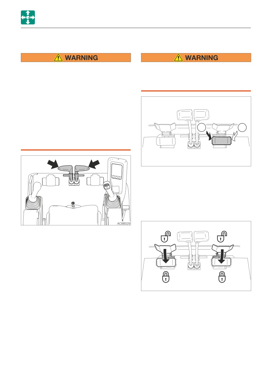
Boom swing pedal
• Before operating the travel levers/
Keep the pedal cover to the locked
pedals, make sure that the dozer blade
position when not using the pedal.
is to the front of the operator’s seat.
Stepping on a pedal accidentally when it
Remember that when the dozer blade is
is not locked may cause accidents.
to the rear of the operator’s seat, the
travel levers/pedals must be operated in
the reverse direction from when it is to
the front.
• Do not rest your foot on the pedal
unless operating it for traveling. If the
B
A
pedal is accidentally stepped while
working, the machine may suddenly
move and cause serious injury or death.
AD6B031
Use this pedal to operate the boom swing.
(A)
Boom swing right
(B)
Boom swing left
Refer to “Operating the boom swing” on
page 3-17.
Pedal lock
Use these levers/pedals to move forward or
backward and to change directions. Fold the
pedals when not being used.
Refer to “Operating the travel levers” on
page 3-12.
AD6B032
Set the pedal cover over the pedal to lock it.
Open the pedal cover from the pedal to
unlock it.
2-31
Controls
Levers and Pedals
Auxiliary hydraulic pedal
Selector lever
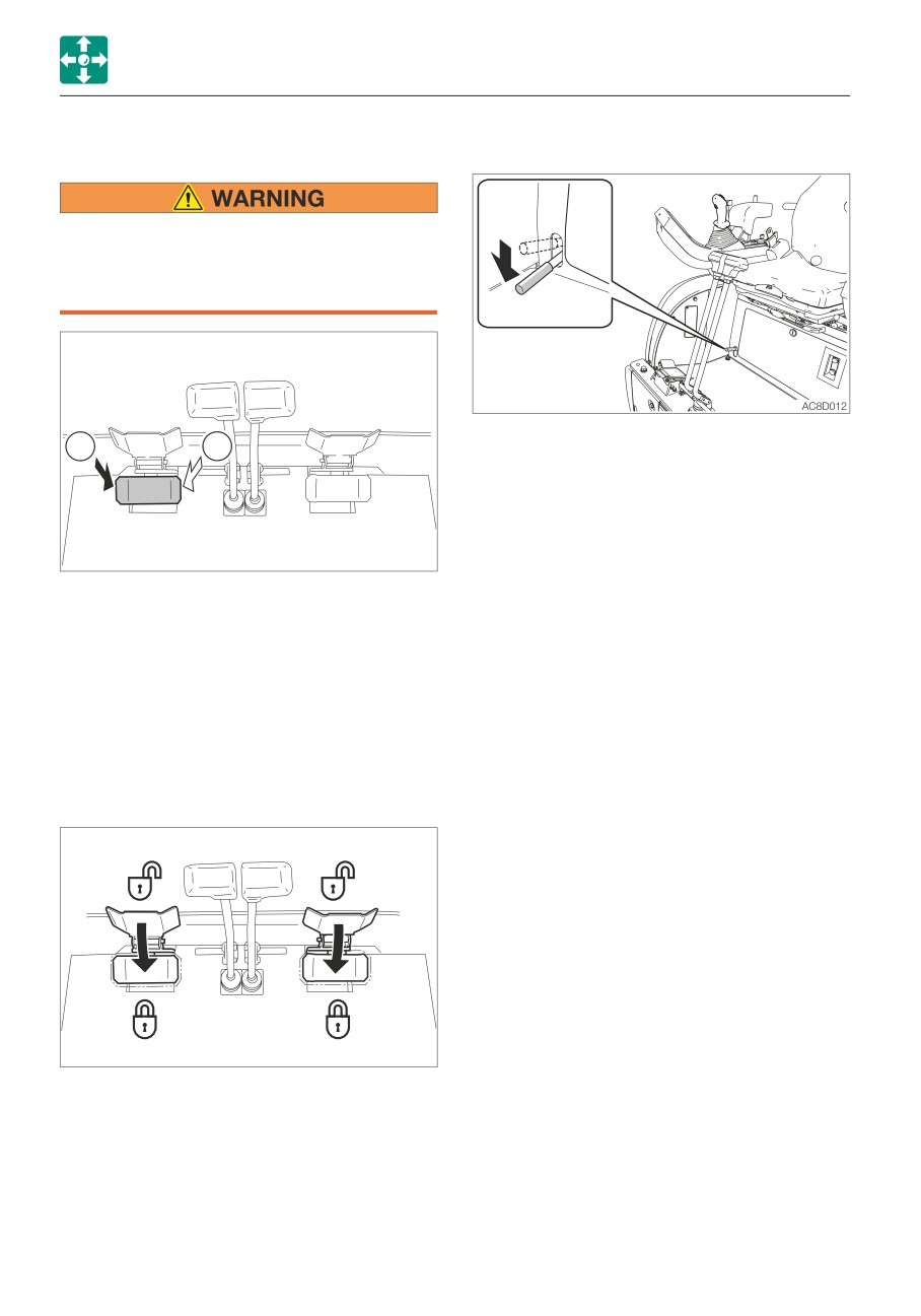
Keep the pedal cover to the locked
position when not using the pedal.
Stepping on a pedal accidentally when it
is not locked may cause accidents.
This lever is used to change the crawler
A
B
width. The operation of the dozer blade
cylinder and the span cylinder is switched
with this lever.
1. Change the crawler width by moving the
blade lever while depressing this lever.
AD6B033
This pedal controls the flow of the oil in the
auxiliary hydraulic circuit.
(A)
Hydraulic oil flows to left auxiliary
hose.
(B)
Hydraulic oil flows to right auxiliary
hose.
Refer to “Auxiliary hydraulic lines” on page
2-42.
Pedal lock
AD6B032
Set the pedal cover over the pedal to lock it.
Open the pedal cover from the pedal to
unlock it.
2-32
Memo
2-33
Controls
Accessories
Outlets
Accessories
Heater
• Always be sure to allow sufficient
ventilation.
• Do not place combustible or explosive
objects near the air outlets.
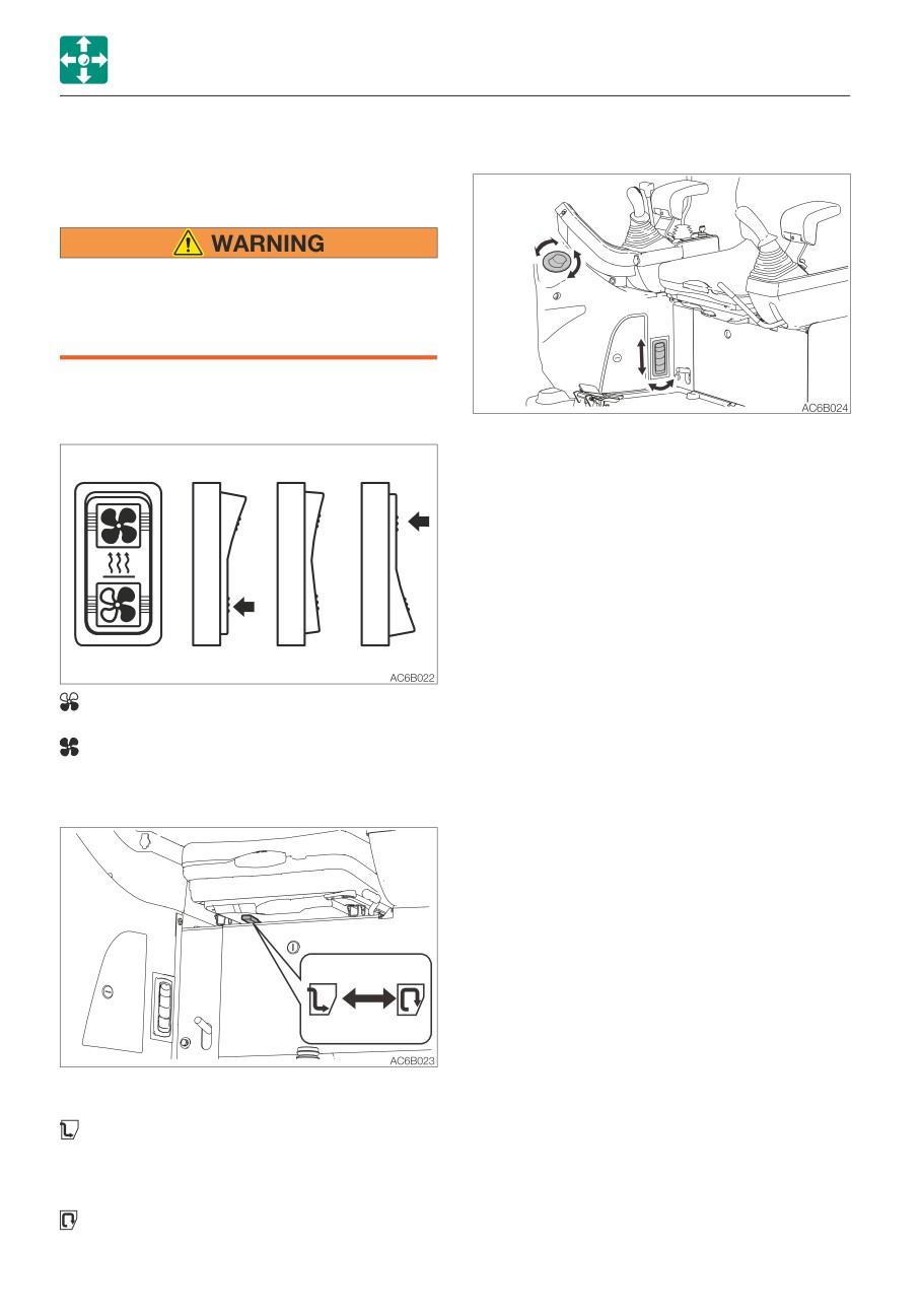
Heater fan switch
Move the louver up and down or left and
right to adjust the air flow direction and
amount.
............. Low
Neutral
OFF
............. High
Ventilation/Circulation lever
Use this lever to switch between Ventilation
and Circulation.
Full ventilation:For heating with
ventilation. Intake of
external air. Defrosting
the windows.
Circulation:Quick heating or when
external air is dirty.
2-34