Takeuchi Mini excavator TB230 (No.130000003~). Operator's Manual (2014) - page 3
CONTROLS
INSTRUMENT CLUSTER
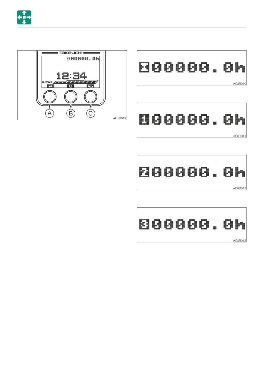
FUNCTION OF EACH KEY
1. Hour meter
2. Trip meter 1
The functions are as below in the Home
screen. The different functions appear in the
other screens.
3. Trip meter 2
A. Stopping the alarm or switching the
display between Functions and
Warnings
· Pressing the (A) key while the alarm is
sounding stops the alarm.
· Pressing the (A) key to switch the
display; Functions (Page 1), Functions
(Page 2), and Warnings (Page 3).
4. Trip meter 3
B. Meter switching
Pressing and holding the (B) key for two
seconds or more each time the display
changes as follows:
5. Returns to the hour meter
· When the (B) key is pressed, the display
changes in the following order.
2-34
CONTROLS
INSTRUMENT CLUSTER
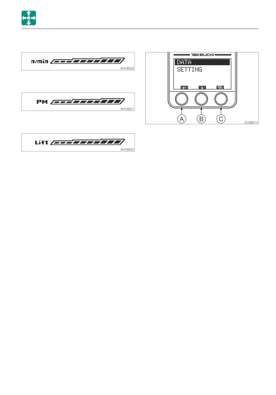
1. Tachometer
MENU SCREEN
2. PM accumulation rate
3. Lift load factor
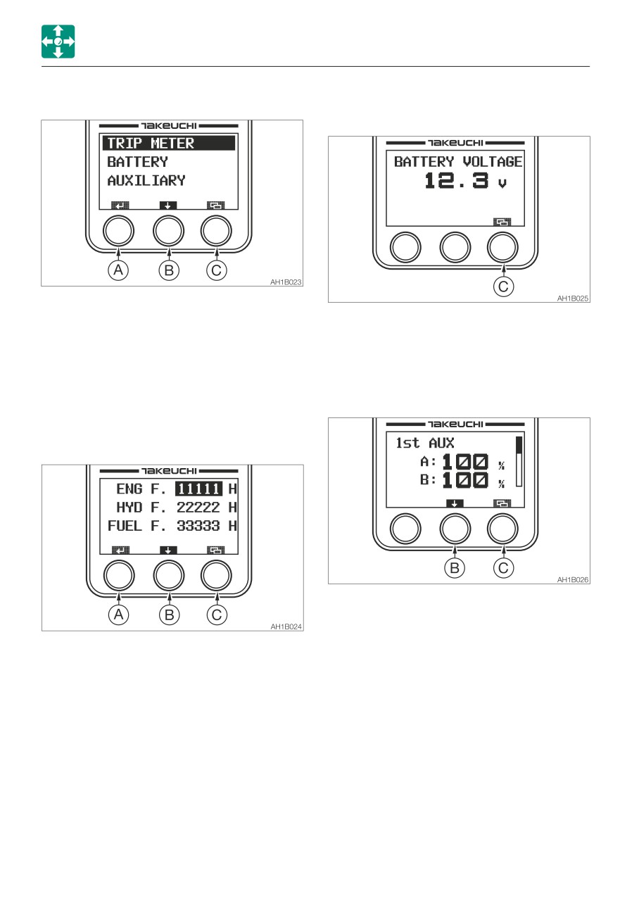
Press the (A) key to proceed to the screen
selected by the bar.
Press the (B) key to move the selection bar.
Press the (C) key to return to the Home
screen.
4. Return to the engine RPM.
• DATA
C.Menu/trip meter reset
The trip meter for maintenance, battery
· Pressing the (C) key switches to the
and auxiliary circuits can be checked.
Menu screen.
Unlike the trip meter displayed on the Main
· Pressing and holding the (C) key for
screen, data items on the engine oil filter,
three seconds or more while the trip
hydraulic oil filter and fuel filter are included
meter is displayed returns the trip meter
so that you can use them as a guideline for
to “0”.
replacement.
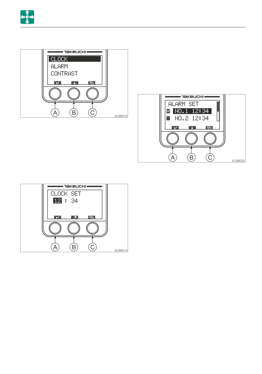
• SETTING
Time, alarm and contrast can be set.
2-35
CONTROLS
INSTRUMENT CLUSTER
DATA SCREEN (DATA)
• Battery (BATTERY)
Displays the battery voltage.
Press the (A) key to proceed to the screen
selected by the bar.
Press the (C) key to return to the DATA
Press the (B) key to move the selection bar.
screen.
Press the (C) key to return to the Menu
screen.
• Auxiliary circuit (AUXILIARY)
Displays the flow rate in the auxiliary
• Trip meter (TRIP METER) for
circuits of the 1st, 2nd or 3rd.
maintenance
The trip meters for the engine oil filter,
hydraulic oil filter or fuel filter are displayed.
Each time the (B) key is pressed, the
auxiliary circuit is displayed in this order:
Auxiliary 1st, Auxiliary 2nd and Auxiliary
Press and hold the (A) key for at least five
4th.
seconds resets the selected trip meter to
Press the (C) key to return to the Data
“0”.
screen.
Press the (B) key to move the selection bar.
Press the (C) key to return to the DATA
screen.
2-36
CONTROLS
INSTRUMENT CLUSTER
SETTING SELECTION SCREEN (SETTING)
e. Press the (C) key cancels editing and to
return to the Setting Selection screen.
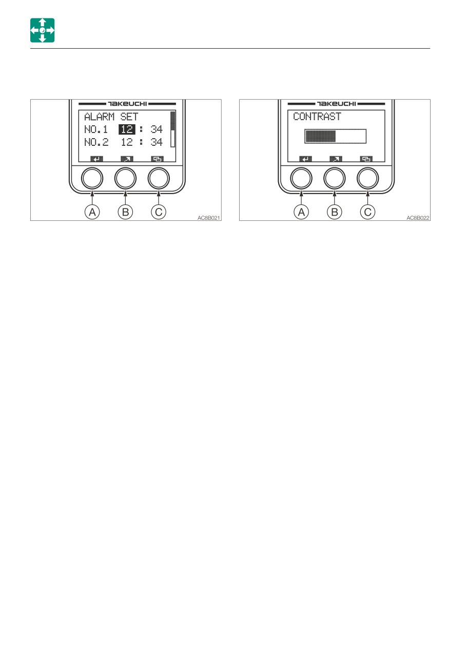
• Alarm setting (ALARM)
Five patterns of alarm setting are
available.
Alarm function can be set to on or off
within the five patterns.
Press the (A) key to proceed to the screen
selected by the bar.
Press the (B) key to move the selection bar.
Press the (C) key to return to the Menu
screen.
• Time setting (CLOCK)
The time to be displayed on the Home
a. When the selection bar is at ALARM,
screen can be set here.
press the (A) key to proceed to the alarm
setting screen (ALARM SET).
b. Press the (A) key in this screen to place
a checkmark in the box at the left of the
setting bar. Press the (A) key again to
remove the checkmark.
The alarm setting cannot be changed
only by placing or removing a
checkmark.
c. Press and hold the (A) key for at least
two seconds to complete the setting
and to return to the Setting Selection
screen.
a. When the selection bar is at CLOCK,
Be sure to perform the above operation
press the (A) key to proceed to the time
when you wish to set the alarm.
setting screen (CLOCK SET).
A clock symbol is displayed on the
b. Pressing the (A) key in this screen moves
Home screen.
the selection bar and flashes the figures
d. Press the (B) key to move the selection
on the bar.
bar.
Setting range: hours, 1 to 24; minutes,
e. Press and hold the (B) key for at least
00 to 59
three seconds to enter the alarm time
c. Press the (B) key to increase the number
setting mode.
value selected.
f. Press the (C) key to cancel editing and
Press and hold the (B) key to rapidly
to return to the Setting Selection screen.
increase the number value selected.
Checked
On
d. Press and hold the (A) key for at least
Unchecked
Off
two seconds to complete the setting
and to return to the Setting Selection
screen.
2-37
CONTROLS
INSTRUMENT CLUSTER
• Alarm time setting mode
• Contrast setting (CONTRAST)
Sets the time for alarm.
Adjust the LCD contrast.
a. Select the item to be set in the alarm
a. When the selection bar is at CONTRAST,
setting screen (ALARM SET).
press the (A) key to proceed to the
b. Press and hold the (B) key for at least
contrast setting screen (CONTRAST).
three seconds to enter the alarm time
b. To increase contrast, press the (B) key.
setting mode.
The bar advances to the right.
c. Press the (A) key in this screen to move
Press and hold the (B) key to rapidly
the selection bar and to flash the figures
advance the bar.
on the bar.
Once the bar reaches the right end
Setting range: hours, 1 to 24; minutes,
(highest contrast), it returns to the left
00 to 59
end (lowest contrast).
d. Press the (B) key to increase the number
c. Press and hold the (A) key for at least
value selected.
three seconds to complete the setting
Press and hold the (B) key to rapidly
and to return to the Setting Selection
increase the number value selected.
screen.
e. Press and hold the (A) key for at least
d. Press the (C) key to cancel editing and
two seconds to complete the setting
to return to the Setting Selection screen.
and to return to the Setting Selection
The changes made to the setting are
screen.
reflected, but they will be removed when
f. Press the (C) key to cancel editing and
the starter switch is turned off.
to return to the Setting Selection screen.
2-38
CONTROLS
INSTRUMENT CLUSTER
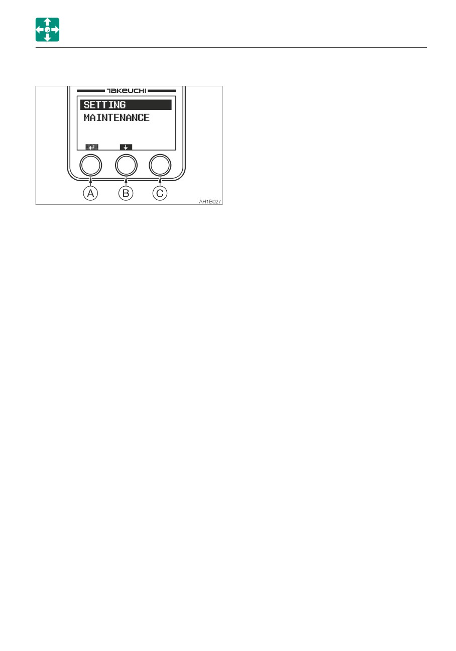
SIDE MENU SCREEN
To display the side menu, turn the starter
switch from the OFF to the ON position while
pressing the (C) key.
Press the (A) key to proceed to the screen
selected by the bar.
Press the (B) key to move the selection bar.
• SETTING
The flow rate ratio of the auxiliary circuits
(Auxiliary 1st, Auxiliary 2nd and Auxiliary
4th) can be set.
• MAINTENANCE
Diagnosis and failure record can be
checked.
2-39
CONTROLS
INSTRUMENT CLUSTER
SETTING SELECTION SCREEN (SETTING)
Initial
A/B common,
Variable
condition
standard flow
range
100%
Auxiliary 1st
= 54 L/min
10 to 100%
No. 1
( 14.3 US gpm)
75%
Auxiliary 1st
= 40.5 L/min
10 to 100%
No. 2
( 10.7 US gpm)
50%
Auxiliary 1st
= 27 L/min
10 to 100%
No. 3
( 7.1 US gpm)
Press the (A) key to proceed to the screen
The table shows the 1-way flow rate when
selected by the bar.
there is no load.
Press the (B) key to move the selection bar.
Press the (C) key to return to the side menu
screen.
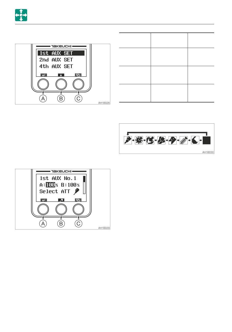
• Auxiliary 1st flow rate setting
(1st AUX SET)
Set the flow rate ratio for the No. 1, No. 2
and No. 3rd in the Auxiliary 1 circuit.
c. When the selection bar is at a symbol of
attachment, press the (B) key to change it
to the desired symbol.
Select the symbol representing the
attachment to be used.
d. The setting for Auxiliary 1 No. 2 and
Auxiliary 1 No. 3 can be done using the
same procedure as above.
e. Press and hold the (A) key for three
seconds or more to complete the setting
and return to the setting selection screen.
f. Press the (C) key to cancel editing and to
return to the setting selection screen.
a. Pressing the (A) key in this screen moves
the selection bar and flashes the figures
on the bar.
b. Press the (B) key to increase the number
value selected.
Press and hold the (B) key for at least one
second to rapidly increase the number
value selected.
2-40
CONTROLS
INSTRUMENT CLUSTER
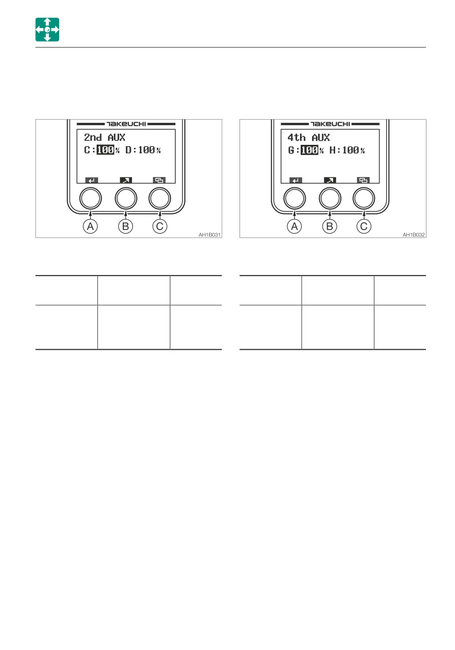
• Auxiliary 2nd flow rate setting
• Auxiliary 4th flow rate setting
(2nd AUX SET)
(4th AUX SET)
Set the flow rate ratio for the Auxiliary 2nd
Set the flow rate ratio for the Auxiliary 4th
circuit.
circuit.
a. For the key operation, refer to the Auxiliary
a. For the key operation, refer to the Auxiliary
1st flow rate setting section.
1st flow rate setting section.
Initial
Variable
Initial
Variable
Standard flow
Standard flow
condition
range
condition
range
C/D 100%
G/H 100%
Auxiliary 2nd
= 21.6 L/min
10 to 100%
Auxiliary 4th
= 21.6 L/min
10 to 100%
( 5.7 US gpm)
( 5.7 US gpm)
2-41
CONTROLS
INSTRUMENT CLUSTER
MAINTENANCE
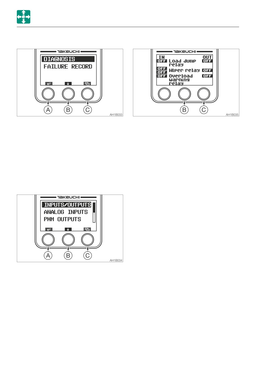
· Inputs/outputs (INPUTS/OUTPUTS)
Diagnosis and failure record can be checked.
The 9-page diagnosis data can be
Press the (A) key to proceed to the screen
displayed.
selected by the bar.
Press the (B) key to display a different
Press the (B) key to move the selection bar.
page.
Press the (C) key to return to the side menu
Press the (C) key to return to the
screen.
Diagnosis screen.
• Diagnosis (DIAGNOSIS)
Input/Output, Analog Input, PWM Output,
Engine Control Module (ECM) can be
checked.
Press the (A) key to proceed to the screen
selected by the bar.
Press the (B) key to move the selection bar.
Press the (C) key to return to the
Maintenance screen.
2-42
CONTROLS
INSTRUMENT CLUSTER
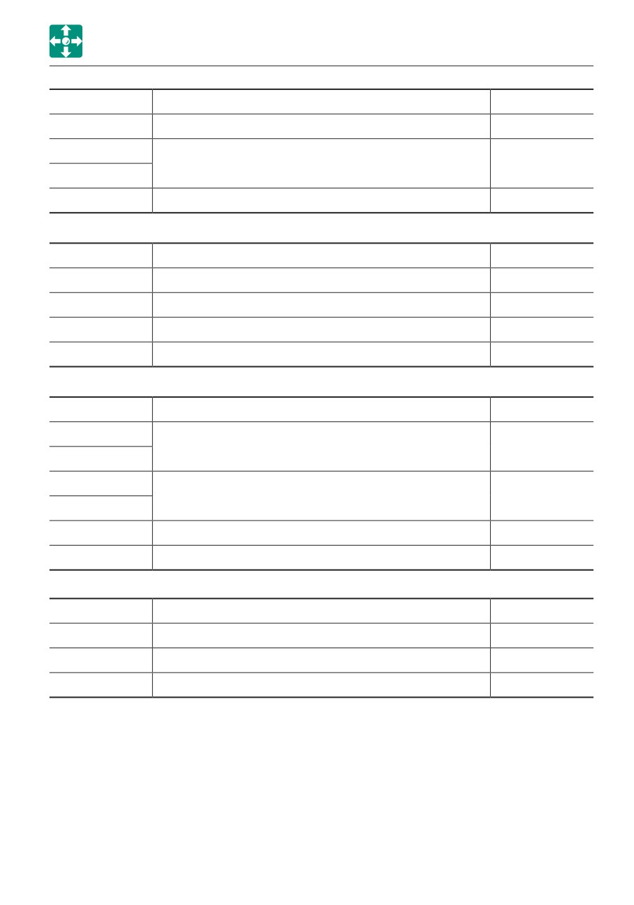
IN
1 page
OUT
OFF/ON
Load dump relay
OFF/ON
OFF/I
Wiper relay
OFF/ON
OFF/C
OFF/ON
Overload warning relay
OFF/ON
IN
2 page
OUT
OFF/ON
Blade float relay
OFF/ON
OFF/ON
Safety lock SOL.
OFF/ON
OFF/ON
Buzzer
OFF/ON
OFF/ON
AUX auto depress SOL.
OFF/ON
IN
3 page
OUT
OFF/G
Travel speed SOL.
OFF/ON
OFF/L
OFF/G
AUX3 SOL.
OFF/ON
OFF/F
OFF/2
AUX2/4 SOL.
OFF/ON
OFF/S
Swing/Adjust SOL.
OFF/ON
IN
4 page
OUT
OFF/ON
Blade right angle SOL.
OFF/ON
OFF/ON
Blade left angle SOL.
OFF/ON
OFF/ON
1 Way SOL.
OFF/ON
2-43
CONTROLS
INSTRUMENT CLUSTER
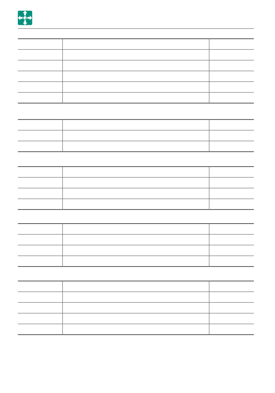
IN
5 page
OUT
OFF/ON
Option AUX4
OFF/ON
OFF/ON
Deceleration button
OFF/ON
OFF/ON
AUX2/4 SW
OFF/ON
OFF/ON
PWR mode SW
OFF/ON
OFF/ON
Highland mode SW
OFF/ON
IN
6 page
OUT
OFF/ON
Engine discriminate (Yanmar)
OFF/ON
OFF/ON
Automatic deceleration SW
OFF/ON
IN
7 page
OUT
OFF/ON
AUX1 flow rate select SW
OFF/ON
OFF/ON
Option 2 piece boom
OFF/ON
OFF/ON
Selector button (2 piece boom)
OFF/ON
IN
8 page
OUT
OFF/ON
AUX3 pressure SW
OFF/ON
OFF/ON
Pressure SW(auto decel)
OFF/ON
OFF/ON
Air cleaner filter clogging
OFF/ON
IN
9 page
OUT
OFF/ON
Water separator warning SW
OFF/ON
OFF/ON
Glow
OFF/ON
OFF/ON
AC compressor
OFF/ON
OFF/ON
BAT charge
OFF/ON
2-44
CONTROLS
INSTRUMENT CLUSTER
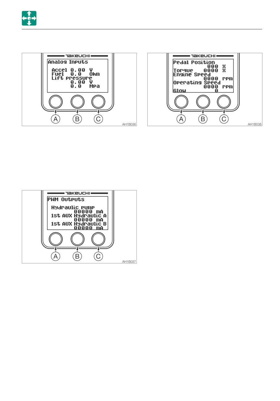
· Analog inputs (ANALOG INPUTS)
· Engine Control Module (ECM)
Displays the analog input information in
Displays the engine output information in
one page.
three pages.
Accel
0.00 V
Fuel
0.0 Ohm
Page 1
Lift pressure
0.00 V
Pedal Position
000 %
0.0 Mpa
Torque
0000 %
Engine Speed
0000 rpm
·
PWM outputs (PWM OUTPUTS)
Operating Speed
0000 rpm
Glow
0
Page 2
Coolant Temp.
000 °C
Fuel Temp.
000 °C
Oil Pressure
0000 kPa
Fuel Rate
0000 L/h
Barometric Pressure
000 kPa
Page 3
Air Inlet Temp.
000 °C
Boost Pressure
000 kPa
Displays the output information on the
Boost Temp.
000 °C
pump and the auxiliary circuits in two
Battery Voltage
0000 V
pages.
Page 1
Hydraulic pump
00000 mA
1st AUX Hydraulic A
00000 mA
1st AUX Hydraulic B
00000 mA
Page 2
2/4 AUX
Hydraulic C/G
00000 mA
2/4 AUX
Hydraulic D/H
00000 mA
2-45
CONTROLS
INSTRUMENT CLUSTER
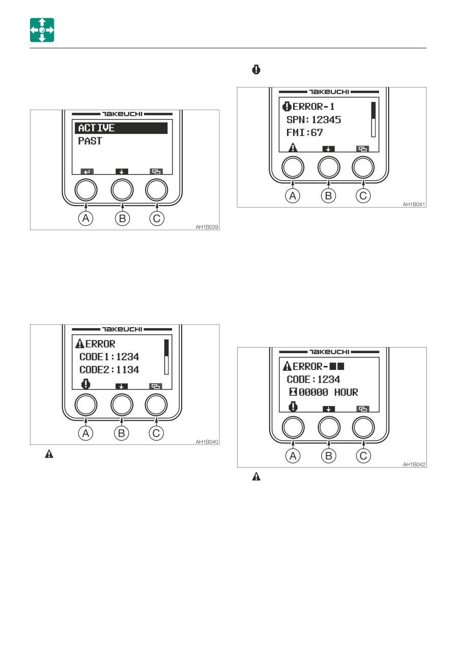
• Failure Record (FAILURE RECORD)
........ Engine error code
The Active Failure Record data and the
Past Failure Record data can be checked.
Pressing the (A) key while the Vehicle
Error Code List is displayed changes the
Press the (A) key to proceed to the screen
screen to the Engine Error Code List. The
selected by the bar.
three latest code SPNs and the FMIs are
Press the (B) key to move the selection bar.
displayed.
Press the (C) key to return to the
Press the (B) key to display a different
Maintenance screen.
page.
Pressing the (C) key returns to the Failure
· Active Failure Record (ACTIVE)
Record screen.
· Past Fault History (PAST)
........ Vehicle error code list
Pressing the (A) key while the Engine
Error Code List is displayed changes the
........ Vehicle Error Code 1 to 12
screen to the Vehicle Error Code List.
When the (A) key is pressed while the
Four latest codes are displayed.
past engine error codes are displayed,
the display changes to the past vehicle
error code screen. The fault history data
is displayed with the latest one at the top,
as well as with the serial numbers (1 to
12) attached. The most recent time of
fault occurrence recorded by the hour
meter is also displayed.
2-46
CONTROLS
INSTRUMENT CLUSTER
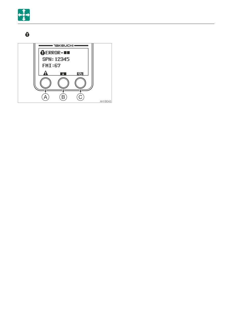
........ Engine error code 1 to 12
Pressing the (A) key while the past vehicle
error codes are displayed changes to the
past engine error code screen. The fault
history data is displayed with the latest
code SPNs and FMIs as well as the serial
numbers of 1 to 12.
Press the (B) key to display a different
page.
Pressing the (C) key returns to the Failure
Record screen.
2-47
CONTROLS
SWITCHES
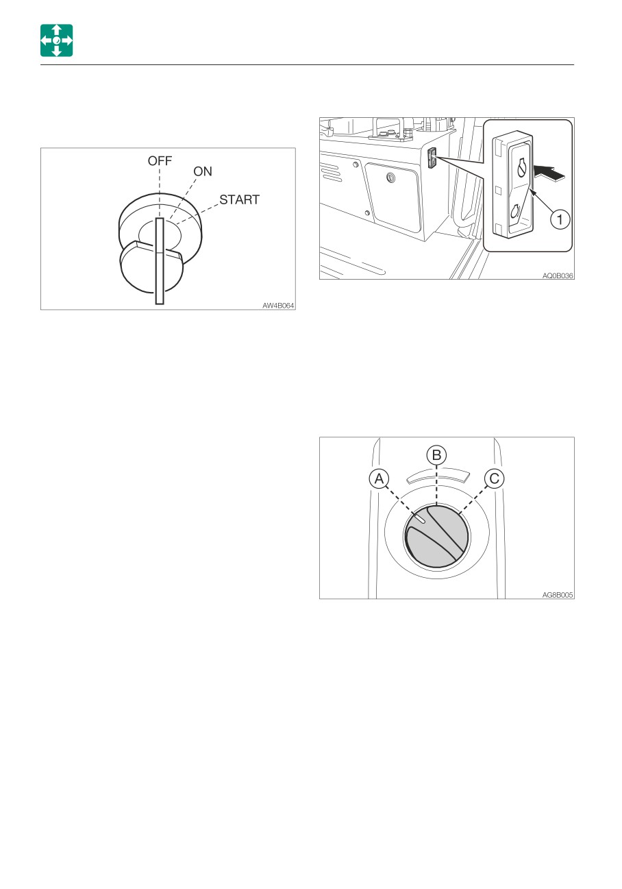
ENGINE SHUTDOWN SWITCH
SWITCHES
STARTER SWITCH
This switch is used to shutdown the engine if
it fails to stop, due to machine failure or
IMPORTANT: Do not repeatedly switch
breakage, when the starter switch is set to
the key from OFF to ON and ON to OFF
the OFF position.
over a short period. Doing so will cause
1. Press the switch (1).
engine breakdown.
2. After use, reset the switch (1).
OFF
Position for stopping the engine
and inserting or removing the key.
THROTTLE CONTROLLER
ON
Position in which the engine is
running. At this position, all the
electrical equipment is functional.
When the coolant temperature is
too low, the engine is
automatically preheated.
START Position for starting the engine.
When the key is released, the
switch automatically returns to the
ON position.
This controls the engine speed.
(A)
Low idling
(B)
Medium speed
(C)
Maximum speed
2-48
CONTROLS
SWITCHES
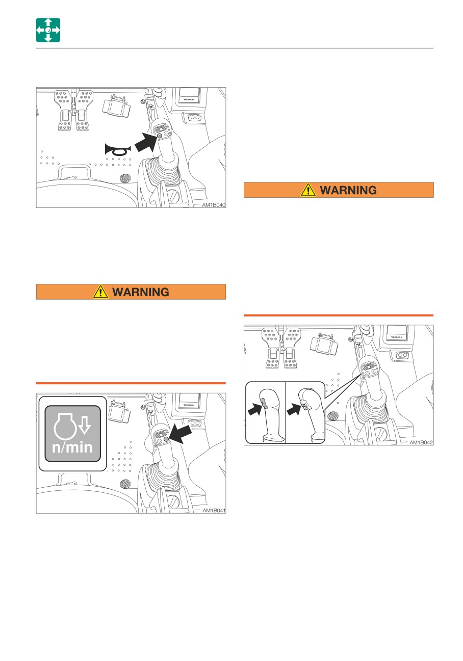
HORN BUTTON
Note: This deceleration button is capable of
decreasing the engine speed and reducing
the fuel consumption, with a simple
operation, in a situation such as when little
engine output is required and thus the
operating or the travel levers are in neutral.
TRAVEL SPEED BUTTON
When a load greater than a set value is
Press the button situated on the right
applied during traveling in 2nd (high)
operating lever to blow the horn.
speed, the speed will automatically slow
down to 1st (low) speed. When the load
becomes lighter, the speed will increase
DECELERATION BUTTON
and return to 2nd (high) speed. It should
be noted that the travel speed changes
depending on the load condition (for
machines with the automatic travel shift-
Before operating the deceleration button,
down system).
set the operating lever to the neutral
position and take your foot off the pedals.
If the deceleration button is pressed while
driving, the machine’s operating speed
will abruptly change to result in a
dangerous situation.
Press this switch to set the travel speed to
2nd (high) speed. Press it again to return to
1st (low) speed.
Press this button on the right operating lever
to lower the engine speed to low idling.
Press the button again to return to the
engine speed set with the throttle controller.
For safety reasons, it is designed that the
deceleration function is activated to set the
engine revolutions to low idling whenever the
engine is started.
Cancel the deceleration mode by pressing
the deceleration button as necessary.
2-49
CONTROLS
SWITCHES
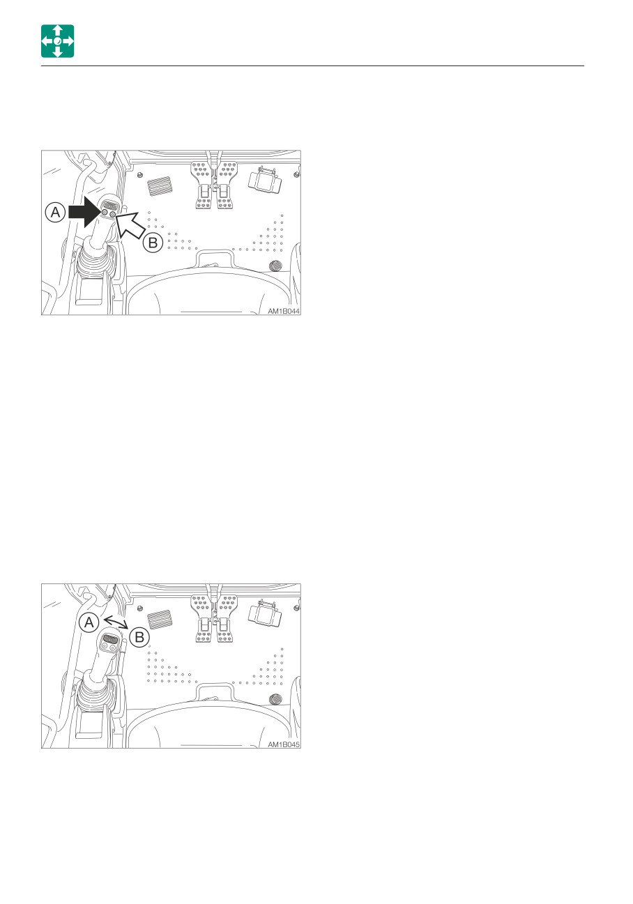
AUXILIARY 1ST SWITCHES
Refer to “Auxiliary hydraulic lines (If
equipped)” on pages 2-70 to 2-74.
Auxiliary hydraulic buttons
Press those buttons to control the flow of the
oil in the first auxiliary hydraulic lines.
• Proportional control of the auxiliary
hydraulic circuit is not possible.
(A)
Hydraulic oil flows to the left auxiliary
line (a).
(B)
Hydraulic oil flows to the right auxiliary
line (b).
Slider switch
(Proportional control)
Proportional control allows for slow-to-fast/
fast-to-slow movement of attachment.
Example: If you move the slider switch half
way, the attachment will move at
approximately one-half the speed.
Move this switch to control the flow of the oil
in the first auxiliary hydraulic lines.
(A)
Hydraulic oil flows to the left auxiliary
line (a).
(B)
Hydraulic oil flows to the right auxiliary
line (b).
2-50
CONTROLS
SWITCHES
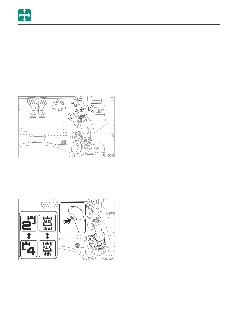
AUXILIARY 2ND/4TH SWITCH
THIRD AUXILIARY HYDRAULIC SWITCH
(IF EQUIPPED)
AND BUTTON (IF EQUIPPED)
Slider switch
Refer to “Third auxiliary hydraulic switch and
(Proportional control)
button (If equipped)” on page 2-73.
Proportional control allows for slow-to-fast/
fast-to-slow movement of attachment.
Example: If you move the slider switch half
AUXILIARY 2/4 SELECT BUTTON
way, the attachment will move at
(IF EQUIPPED)
approximately one-half the speed.
Refer to “Auxiliary 2/4 select button (If
equipped)” on page 2-74.
Move this switch to control the flow of the oil
in the second auxiliary hydraulic lines.
(C):
Hydraulic oil flows to the left auxiliary
line (c).
(D):
Hydraulic oil flows to the right auxiliary
line (d).
To use the auxiliary 4th hydraulic line, press
the auxiliary 2/4 select button to change to
the operation of the auxiliary 4th.
Refer to “Auxiliary hydraulic lines (If
equipped)” on page 2-70 to 2-74.
2-51
CONTROLS
SWITCHES
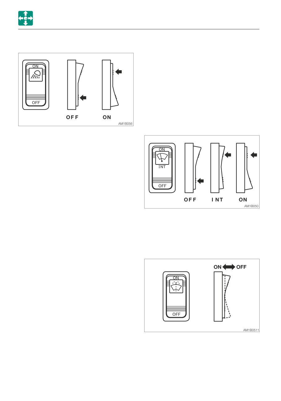
LIGHT SWITCH
WIPER SWITCH
IMPORTANT: If no washer fluid is
discharged, do not operate the washer.
Doing so may damage the pump.
IMPORTANT: Operating the wiper with no
moisture on the windshield will scratch
the glass. Use water or washer fluid when
operating the wiper.
IMPORTANT: In cold climates, the wiper
blade may freeze to the glass. Operating
the wiper forcibly may damage the wiper
motor.
When this switch is turned while the starter
switch is at ON, the lights turn on as follows:
OFF Off
ON Switch lamps, front light, boom light,
side lights and tail lamps will be lit.
(switch lamp is lit)
OFF Off
INT Intermittence operation
ON Continuous operation
WASHER SWITCH
ON Pressing the ON side of the switch
causes the washer to spray washer
fluid. To stop spraying, release the
switch.
2-52
CONTROLS
SWITCHES
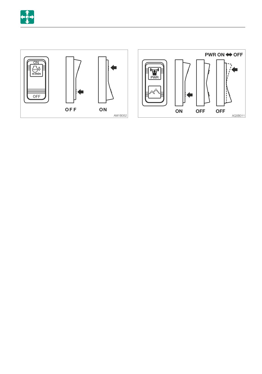
AUTOMATIC DECELERATION SWITCH
POWER/HIGHLAND MODE SWITCH
When the ON side of the switch is pressed,
the deceleration lamp in the instrument
• Power mode
cluster flashes. This flashing stops when the
· Pressing the PWR symbol side of the
deceleration function starts working, and the
switch turns on the Power mode
lamp remains lit while in the deceleration
indicator lamp on the instrument cluster.
mode. The engine speed automatically drops
The maximum engine output is obtained.
to low idle (deceleration mode) four seconds
· STD mode: Pressing the PWR symbol
after the control levers are set to neutral, to
side of the switch again turns off the
reduce fuel consumption. Moving the control
power mode indicator lamp.
levers will cause the speed to return to the
original engine speed.
• Highland mode
Switching from the deceleration button to the
This switch is used to reduce the engine
auto-deceleration switch will first return to
load due to the hydraulic pump. When the
the engine speed set with the throttle
machine is operated at a high-altitude site,
controller. Then, the engine will automatically
the engine output is decreased due to thin
enter the deceleration mode (low idling) if the
air. In such cases, the hydraulic horse
control levers are not operated within four
power is automatically adjusted to prevent
seconds.
the engine from stalling. Use this switch
when the machine is operated at a high-
altitude site.
· Pressing the PWR symbol side of the
switch turns on the Power mode
indicator lamp on the instrument cluster.
· To cancel the highland mode, press the
PWR symbol side halfway to set to the
neutral position. The highland mode
indicator lamp goes out and enters the
lowland mode.
Refer to “Multi-information display” on
page 2-16.
Refer to “Instrument cluster” on page
2-28.
2-53
CONTROLS
SWITCHES
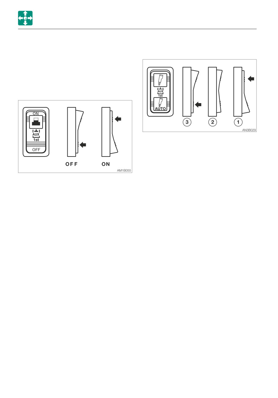
DETENT MODE SWITCH
AUXILIARY 1ST AUTO TANK SWITCH
(AUXILIARY 1ST) (IF EQUIPPED)
(IF EQUIPPED)
IMPORTANT: Do not operate the machine
in the detent mode for a long time. Doing
so will increase the hydraulic oil
temperature and shorten the service life
of the hydraulic units.
Use this switch to change the direction of
hydraulic oil flow in the Aux. 1st line.
(1) When using a hydraulic breaker (1-way
flow)
(2) When using a reversible attachment
(2-way flow)
This switch is used to change the operation
(3) The one-way flow can be set only when
mode of the auxiliary 1st button (A). Pressing
the button “A” of the Aux. 1 is pressed.
the ON side of the switch causes the
(The tank circuit is automatically opened.)
auxiliary button (A) to enter the detent mode.
Pressing the OFF side changes to the
momentary mode.
2-54
CONTROLS
SWITCHES
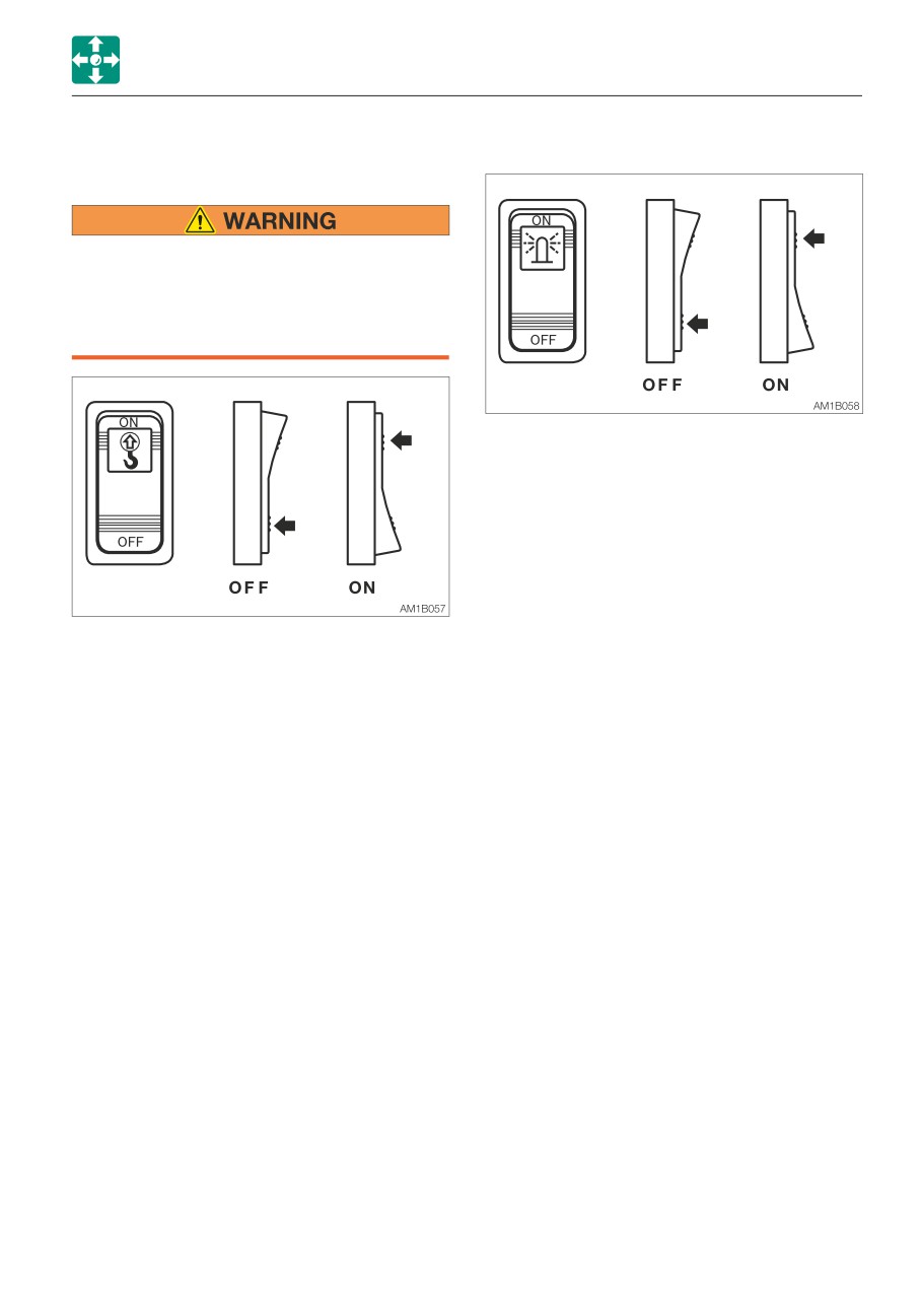
LIFT OVERLOAD WARNING SWITCH
BEACON LAMP SWITCH (IF EQUIPPED)
(IF EQUIPPED)
If the overload is not removed after the
overload warning horn is sounded, the
machine may tip over. If the horn starts
sounding, stop operating the machine
and lighten the load.
When this switch is turned on while the
starter switch is at ON, the lamp turns on as
follows:
OFF
Off
ON
Beacon lamp is lit
If a weight greater than the lifting capacity is
applied or lifted, the overload warning device
is activated and the horn sounds. (When the
lift overload warning switch is turned on.)
OFF
Off
ON
On
2-55
CONTROLS
LEVERS AND PEDALS
OPERATING LEVERS
LEVERS AND PEDALS
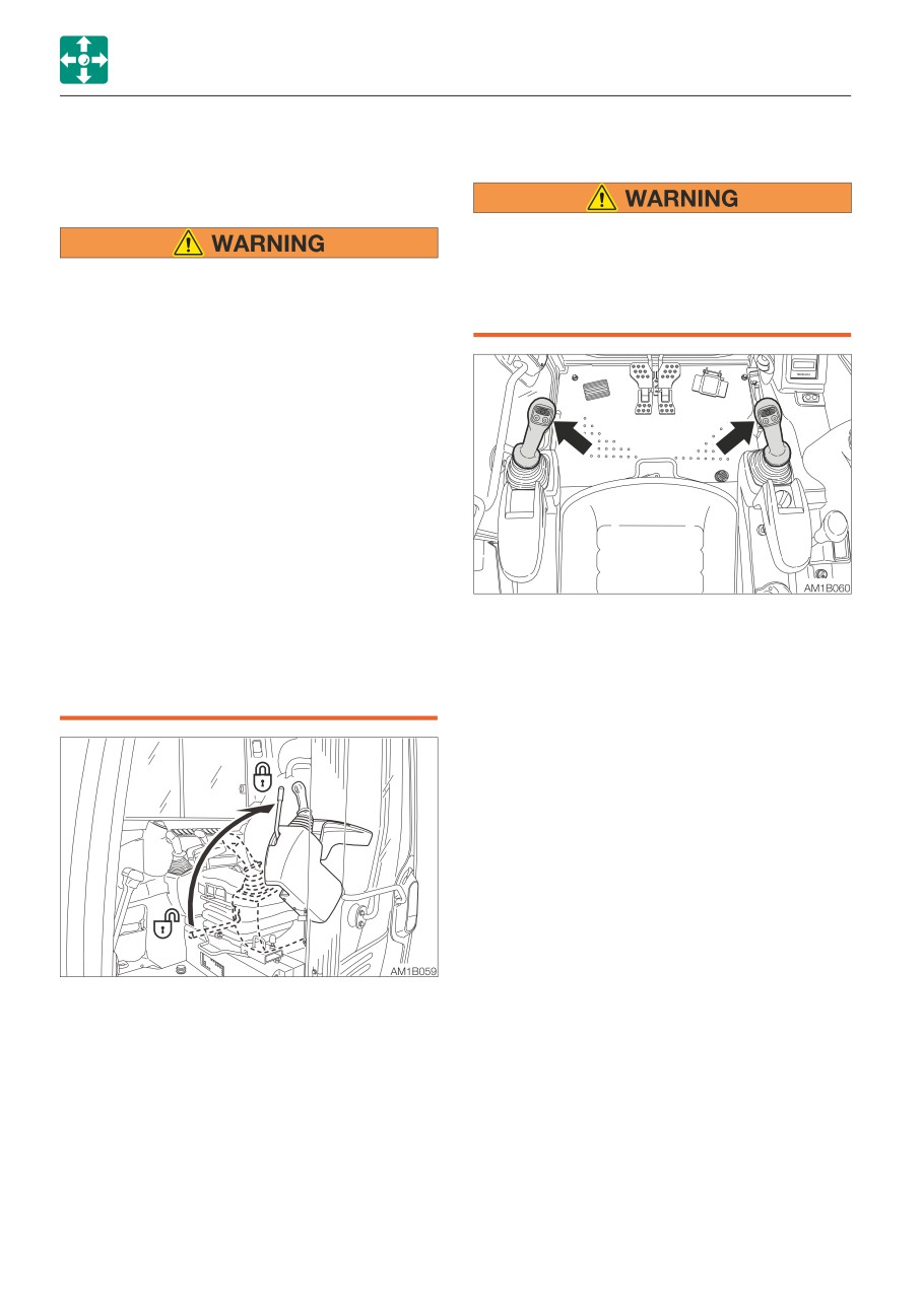
SAFETY LOCK LEVER
• Before starting operation, carefully
check which lever pattern you are going
• Before standing up from the operator’s
to use.
seat to open/close the window or
• It is described using the ISO pattern in
remove/install the lower window, lower
this manual.
the working equipment to the ground,
raise the safety lock levers to engage
the lock and stop the engine. If any
controls should be accidentally touched
when the safety lock levers is lowered
(unlocked), the machine will suddenly
move and cause serious injury or death.
• Be careful not to touch the operating
levers when raising or lowering the
safety lock lever.
• Before leaving the operator’s seat, lower
the working equipment to the ground,
raise the safety lock levers to engage
Use these levers to operate the boom, arm,
the lock and stop the engine. Also, be
bucket and upperstructure.
sure to remove the key, lock the door
Refer to “Lever pattern” on pages 3-6 and
and covers, take it with you and store it
3-7.
in a specified place.
Refer to “Operating the working equipment”
on pages 3-14 and 3-15.
This device is for locking the operations of
hoe attachment, slewing, auxiliary, dozer
blade and traveling.
When the lever is raised, the lever stand
springs up to lock the lever.
2-56
CONTROLS
LEVERS AND PEDALS
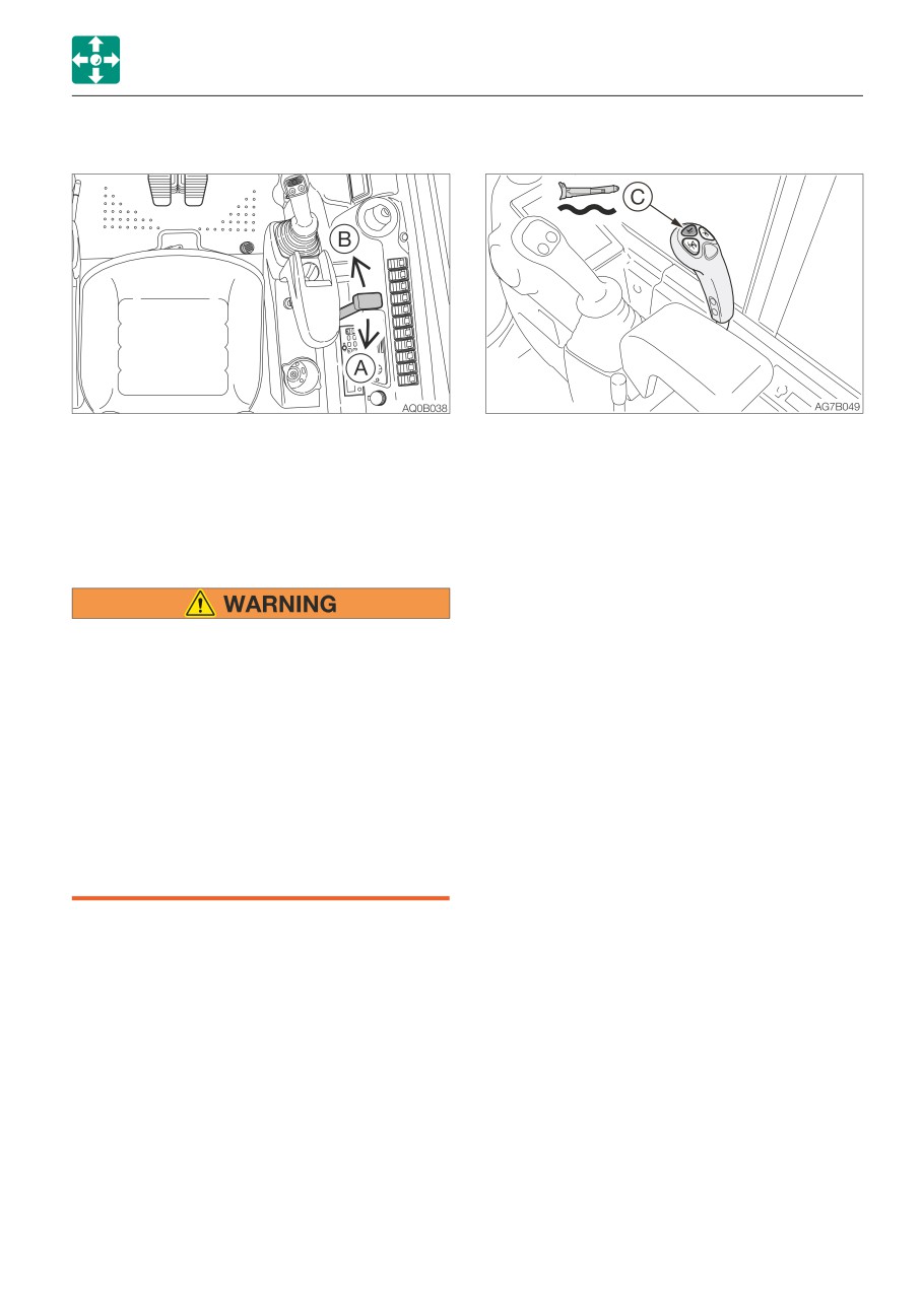
BLADE LEVER
Float operation
Use this lever to operate the dozer blade.
Button (C)
Float mode
(A)
Blade up
Press the float button (C) to
(B)
Blade down
set the dozer blade to the float
Refer to “Operating the dozer blade” on
mode.
page 3-15.
To cancel the float mode,
press the float button (C)
Float button (if equipped)
again. The float mode is
temporally cancelled when the
blade lever is tilted backward.
• Do not press the float button while the
To return to the float mode, tilt
machine is raised by the blade. Doing
the blade lever back to the
so will cause the machine to fall. If you
neutral position. Take caution
must work beneath the raised machine,
when returning to the float
always use a secure support to keep the
mode.
machine raised.
• Do not press the float button while the
blade is raised. Doing so will cause the
blade to fall. Lower the blade to the
ground before pressing the float button.
• Do not travel forward while the blade is
in the float mode.
2-57
CONTROLS
LEVERS AND PEDALS
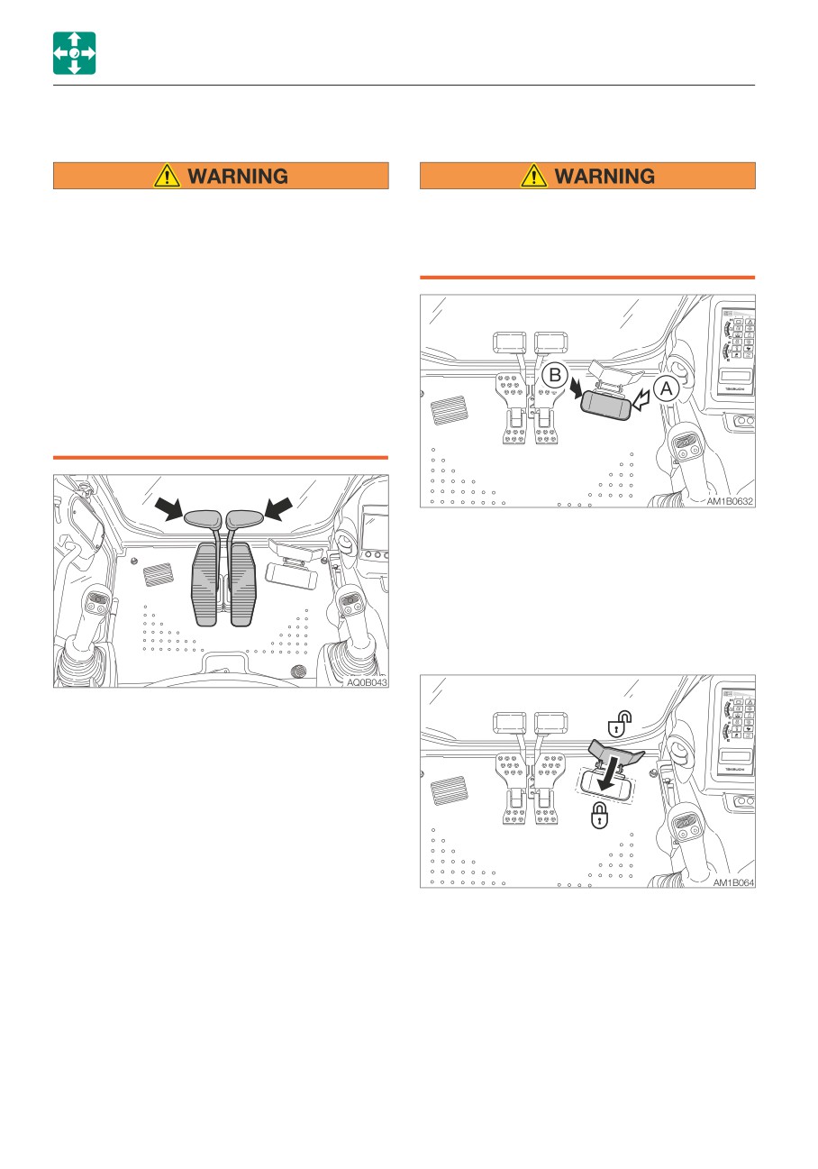
TRAVEL LEVERS/PEDALS
BOOM SWING PEDAL
• Before operating the travel levers/
Keep the pedal cover to the locked
pedals, make sure that the dozer blade
position when not using the pedal.
is to the front of the operator’s seat.
Stepping on a pedal accidentally when it
Remember that when the dozer blade is
is not locked may cause accidents.
to the rear of the operator’s seat, the
travel levers/pedals must be operated in
the reverse direction from when it is to
the front.
• Do not rest your foot on the pedal
unless operating it for traveling. If the
pedal is accidentally stepped while
working, the machine may suddenly
move and cause serious injury or death.
Use this pedal to operate the boom swing.
(A)
Boom swing right
(B)
Boom swing left
Refer to “Operating the boom swing” on
page 3-15.
Pedal lock
Use these levers/pedals to move forward or
backward and to change directions.
Refer to “Operating the travel levers/pedals”
on page 3-10.
Set the pedal cover over the pedal to lock it.
Open the pedal cover from the pedal to
unlock it.
2-58
MEMO
2-59
CONTROLS
ACCESSORIES
Outlets
ACCESSORIES
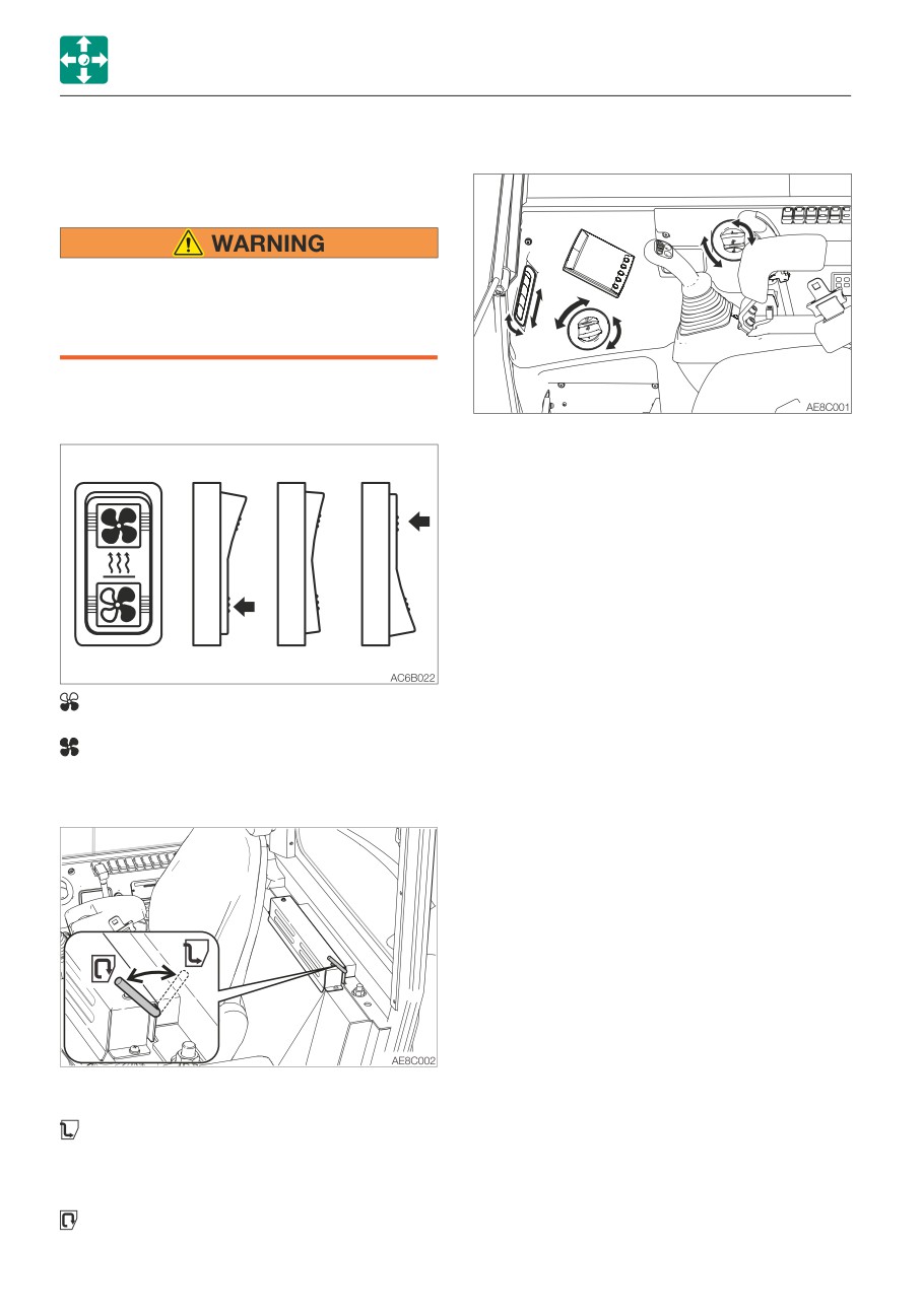
HEATER
• Always be sure to allow sufficient
ventilation.
• Do not place combustible or explosive
objects near the air outlets.
Heater fan switch
Move the louver up and down or left and
right to adjust the air flow direction and
amount.
............. Low
Neutral
OFF
............. High
Ventilation/Circulation lever
Use this lever to switch between Ventilation
and Circulation.
Full ventilation:For heating with
ventilation. Intake of
external air. Defrosting
the windows.
Circulation:Quick heating or when
external air is dirty.
2-60
CONTROLS
ACCESSORIES
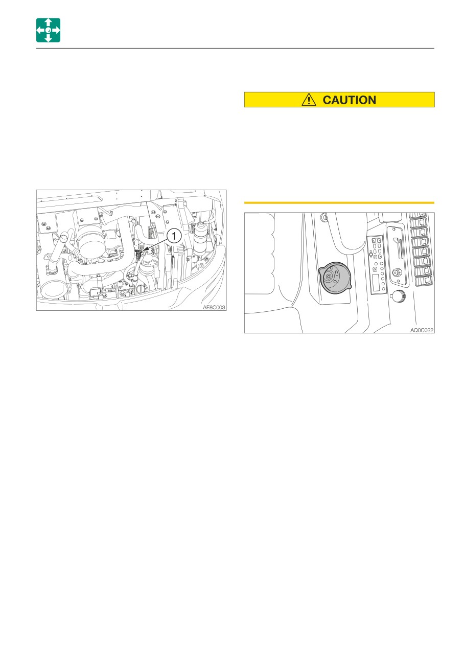
Heater valve
CUP HOLDER
Coolant circulates in the heater even when
the heater switch is turned off.
When the heater is no longer needed, stop
coolant circulation as follows.
• Drinks may be spilled due to vibration
when the machine is operating or
IMPORTANT: Use the valve (1) either fully
traveling. Be particularly careful not to
open or fully closed.
burn yourself with hot drinks.
Cooling water could leak when the valve
• Note that the power supply socket or
is partly opened.
other electric parts may be damaged if
drinks are spilled on them. Be careful
not to spill fluid on them.
1. Park the machine on a level surface and
stop the engine.
2. Open the engine hood.
Use to hold cups or bottles.
3. Turn the valve (1) clockwise until it stops to
close it.
Filters
Clean the filters immediately after operating
in dusty places.
If the filters are clogged, the air flow is
reduced and a booming sound is heard from
the heater unit.
Refer to “Cleaning the air filter (CAB)” on
page 5-41.
2-61
CONTROLS
ACCESSORIES
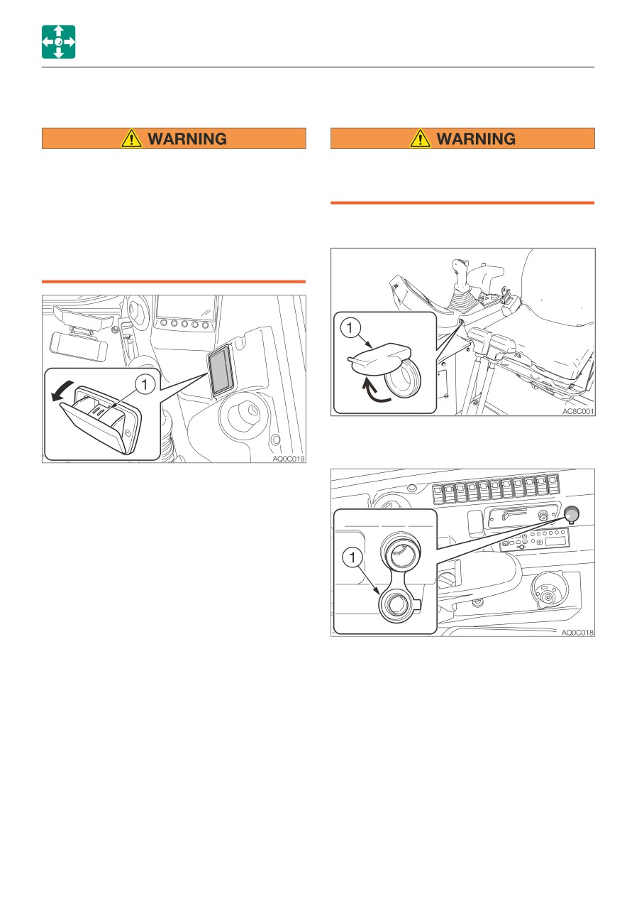
ASHTRAY
POWER SUPPLY SOCKET
• Be sure to extinguish cigarettes and
Use only those electric products which
matches completely before putting
comply with the specifications of these
them in the ashtray, and close the
sockets.
ashtray after each use.
• Do not overfill the ashtray with cigarette
<Canopy>
butts or put in paper or other easily
burnable objects. Doing so could cause
fire.
<Cab>
Pull the ashtray out towards you to use it. To
clean, press the ash discharge button (1) and
pull out the ashtray.
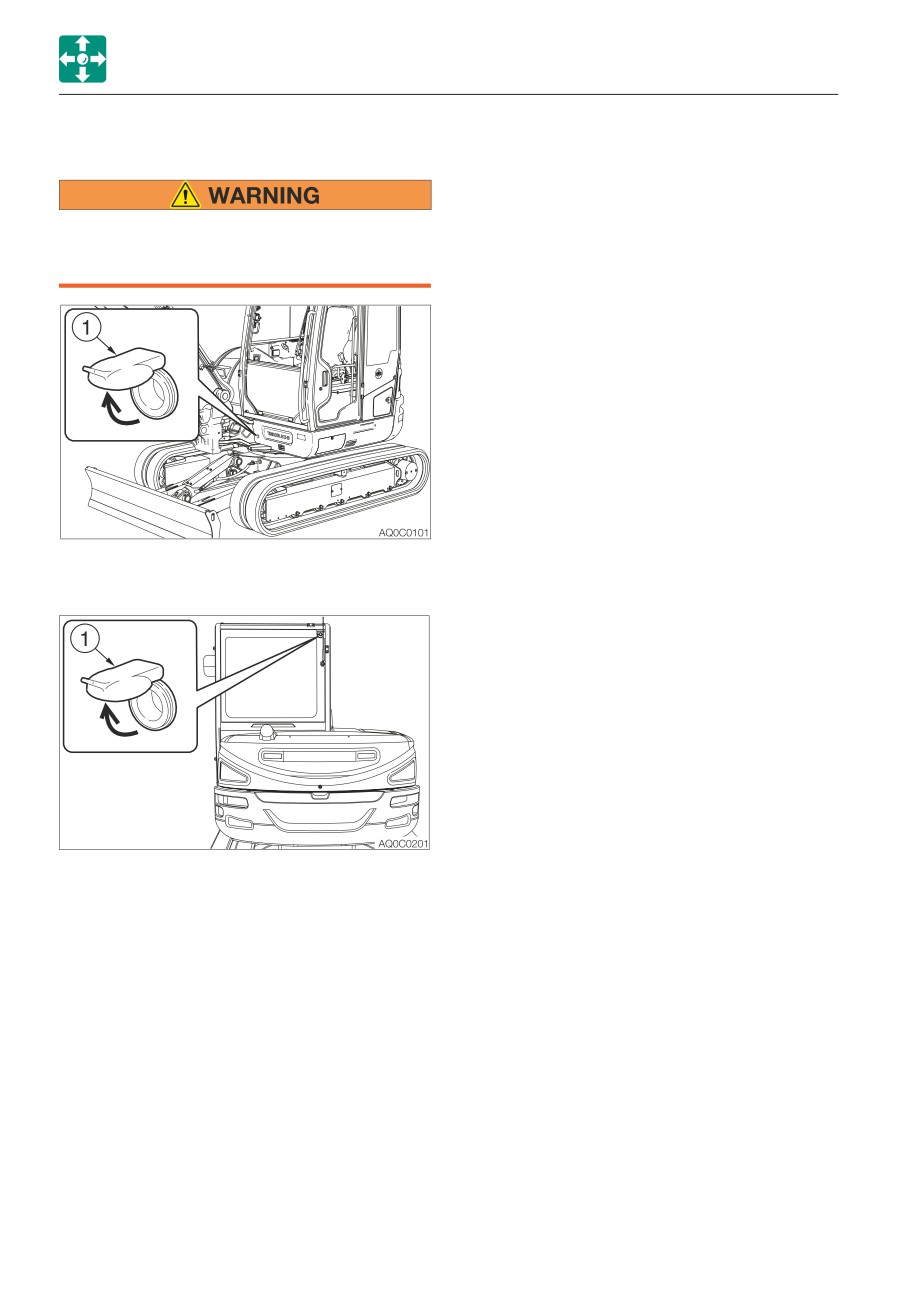
This socket is used to supply power to the
interior electrical components. When using,
be careful not to exceed 12V/5A.
To use, open the cap (1).
2-62
CONTROLS
ACCESSORIES
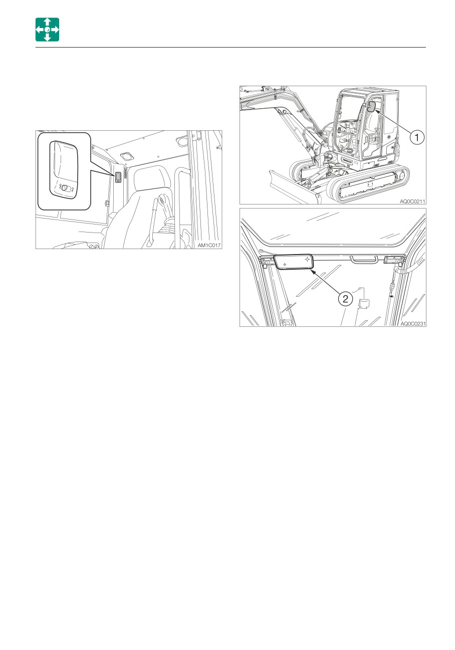
INTERIOR LIGHT
MIRRORS
IMPORTANT: The battery capacity
decreases if the interior light is left on for
a long time when the engine is stopped.
OFF
Remains off all the time.
Neutral position
Lights up for 30 seconds when
the starter switch is turned to OFF
from ON.
ON
Lights up all the time.
Adjust the rear view mirrors and side view
mirrors so that you have a better view.
1. Check the left side rear view
2. Check the rear view.
2-63
CONTROLS
ACCESSORIES
EXTERNAL POWER SOCKETS
Use only those electric products which
comply with the specifications of these
sockets.
For beacon
Use these sockets to connect the external
power supply. When using, be careful not to
exceed 12V/5A.
To use, open the cap (1).
2-64
MEMO
2-65
CONTROLS
ACCESSORIES
RADIO (FOR CAB)
CAUTIONS ON USE
• To ensure safe operation of the machine, always be sure to keep the volume of the
radio down to a level where you can easily hear sounds from outside the machine.
• Do not use the radio for a long time when the engine is stopped. Doing so will drain
the battery and make it difficult or impossible to restart the engine.
• Be careful not to allow water or other liquids to come into contact with the radio.
Otherwise, it may result in malfunction.
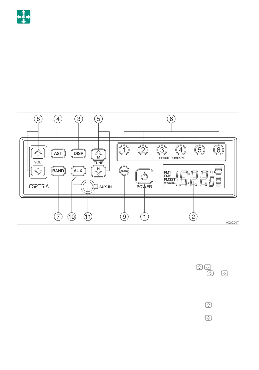
NAMES OF COMPONENTS
(1) POWER button
(4) Auto store/Auto seek station (AST)
Use this button to turn on or off the
Press this button to automatically assign
radio.
receivable radio stations to preset
buttons (1 to 6).
(2) LCD
Displays the time/the receiving frequency
(5) Tuning button (TUNE
)
and the operation mode.
Press and hold this button ( or
) for
one second or more to start seeking the
(3) Display button (DISP)
receivable stations. The seeking stops
Pressing this button while the frequency
when a station is found. To cancel tuning
is displayed on the LCD changes the
halfway, press the button again.
display to the clock. Pressing the button
Pressing the TUNE button
starts
again returns to the frequency. If the
seeking stations with higher frequency.
button is not pressed for five seconds,
Pressing the TUNE button
starts
the display returns to the frequency.
seeking stations with lower frequency.
The frequency changes as either button
is pressed in one second intervals.
2-66
CONTROLS
ACCESSORIES
(6)
Preset buttons (1 to 6) (PRESET
(11)Auxiliary input jack (AUX-IN)
STATION)
Use this jack to connect an external
Each button can store three FM stations
audio source such as a portable music
(FM1, FM2, FM3) and one MW (AM)
player. Pull off the rubber cap and
station. For how to set these buttons,
connect the output terminal (headphone
refer to “Presetting stations”.
jack) of the portable player to the AUX-IN
with the stereo mini-plug (3.5 mm) cord.
(7)
Band button (BAND)
Be sure that jack is closed with the
Pressing this button changes the band
rubber cap when not in use.
from FM1 to FM2, FM3 and MW (AM) in
this order. The received band and its
Playing the radio
frequency appear on the display.
1. Turn the ignition key to the ACC or ON
position, and then press the power button
(8)
VOL buttons
(1) to turn on the radio.
Use these buttons to control the sound
2. Select the band, FM or MW (AM) by
volume. Press the button
to increase
pressing the BAND button.
the volume and the button to
3. Select the station with the preset button or
decrease the sound volume. Press and
the tuning button, and adjust the volume
hold each button to continuously
with the volume button.
increase/decrease the volume.
4. To turn off the radio, press the power
button.
(9)
Clock zero set button (ZERO)
Use this button to set the minute to “00”
Selecting a station-auto select
when it is between “55” to “59” or “01”
Press and hold the TUNE button
for one
to “05”.
second or more to start seeking stations in
The LCD returns to the frequency display
the higher frequencies direction. Press and
if no more operation is performed for five
hold the TUNE button
for one second or
seconds.
more to start seeking stations in the lower
frequencies direction. The radio will stop
(10)Auxiliary input select button (AUX)
seeking when it finds an receivable station
Pressing this button changes the input
and start playing.
source to the external device connected
to the AUX-IN (11) jack. The display of
Selecting a station-manual select
“AUX” appears on the LCD. Pressing the
The selection can be done manually. Press
button again returns to the radio.
the tune
button to seek stations with
higher frequencies. Press the tune
button
to seek stations with lower frequencies.
2-67
CONTROLS
ACCESSORIES
Presetting stations
Auxiliary input (AUX)
1. Press the BAND button to select a band
• Connect a portable audio player and listen
(MW (AM) or FM), and then select the
to your favorite music.
station by pressing the TUNE button for
• Plug a patch cord (without resistor) into the
seeking.
headphone jack of the audio player.
2. To assign the selected station to a preset
• Plug a stereo mini plug (3.5 mm) into the
button, press and hold the button to be
AUX-IN jack on the radio.
assigned for one second or more. The
• To listen to an external portable audio
number of the preset button appears on
player, press the AUX button. (The “AUX”
the LCD.
display appears on the LCD and the
3. For more stations to preset, repeat the
frequency display is changed to the clock
steps 1 and 2 above.
display.)
• If the preset button on which a station
• To return to the radio, press the AUX
has been assigned is pressed and held
button again.
for one second or more, the preset
• When connecting, adjust the sound volume
information will be modified.
level of the audio player so that it is same
• If the stored information is erased during
as that of the radio.
battery replacement on the vehicle,
• Adjust the sound volume of the audio
assign the stations again to the preset
player by using the volume control buttons
buttons.
on the radio.
• Each preset button (1 to 6) can store
• Do not connect a device with a larger
three FM stations (one from each FM1,
output compared with a portable audio
FM2, FM3) and one AM station.
player.
Auto storing (AST)
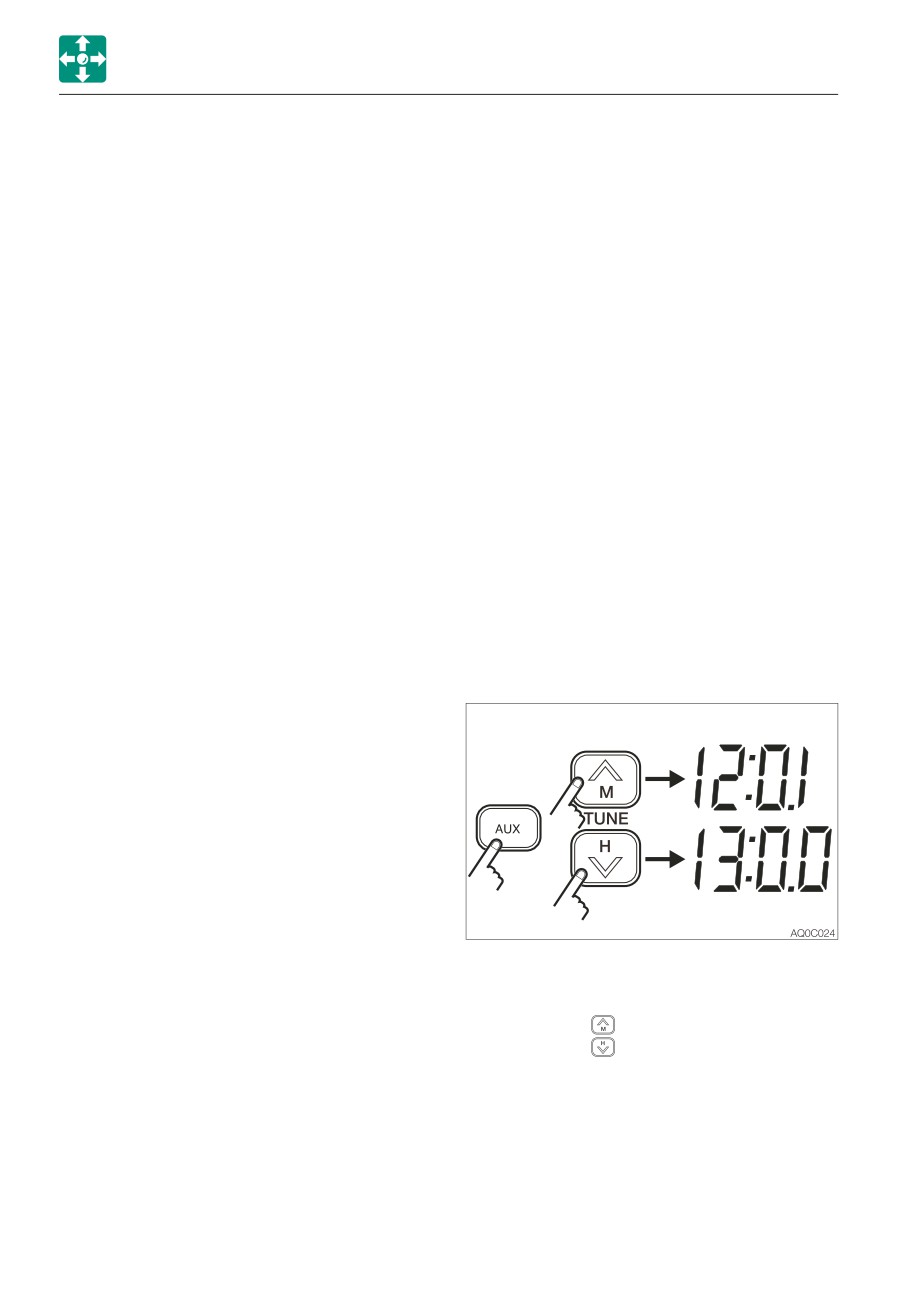
Setting the clock
Press the AST button while playing the radio.
The radio automatically starts seeking the
receivable stations within the band currently
selected and assign each preset button (1 to
6) a station.
Note: The previous stations stored will be
cleared (cancelled) by the auto storing. If the
station stored in the preset button is not
desirable, try to preset the station manually.
• If a frequency is displayed on the LCD,
press the AUX button (auxiliary input) to
display the clock.
• Use the tune
button to set the minute.
Use the tune
button to set the hour.
• To set the minute digits to “00” when they
are from “55” to “59” or from “01” to “05”,
press the ZERO button.
2-68
CONTROLS
ACCESSORIES
Resetting
SPECIFICATIONS
If there are any problems, such as the
Power source:
12/24 VDC (negative
abnormal display of frequency or failure of
ground)
selection, reset the radio by pressing the “4”
Maximum power consumption:
button while pressing the AST button and
3A or less (at max. volume,
the AUX button together. Then, “JP” and the
24 V)
clock display appear on the LCD, indicating
Maximum output power:
that the radio is turned off. Note that the
16 W + 16 W (4Ω) (at 28.8
memory stored in the preset button is
VDC input)
cleared.
5W+5W (4Ω) (at 14.4 VDC
input)
Switching the volume mode when the
Rated output power:
radio is on
12 W + 12 W (10%
Switch the modes between SU and FI by
distortion, 4Ω) (at 28.8
pressing the (1) button while pressing the
VDC input)
AST and AUX buttons together, when the
3.5 W + 3.5 W (10%
radio is on.
distortion, 4Ω) (at 14.4
The SU or FI display appears on the LCD,
VDC input)
followed by the radio turning off by itself.
Dimensions:
178 (W) x 50 (H) x 65 (D)
SU mode:
The volume at power-off is
mm (excluding protrusions)
retained.
Receiving frequency:
FI mode:
The volume at power-off is
MW (AM) 531 to 1602 kHz
reset.
(Europe, Asia), 530 to
1710 kHz (North, Central
and South America)
FM 87.5 to 108 MHz
(Europe, Asia), 87.9 to 108
MHz (North, Central and
South America)
Practical sensitivity:
MW (AM) 32 dB or less
(S/N 20 dB)
FM 12 dB or less (S/N 30
dB)
S/N ratio:
MW (AM) 40 dB or more
FM 50 dB or more
AUX-IN:
Stereo mini jack (3.5 mm);
rated input, 90 mV; 20 kΩ
impedance
Note: Specifications and dimensions may be
changed without notice.
2-69
CONTROLS
ACCESSORIES
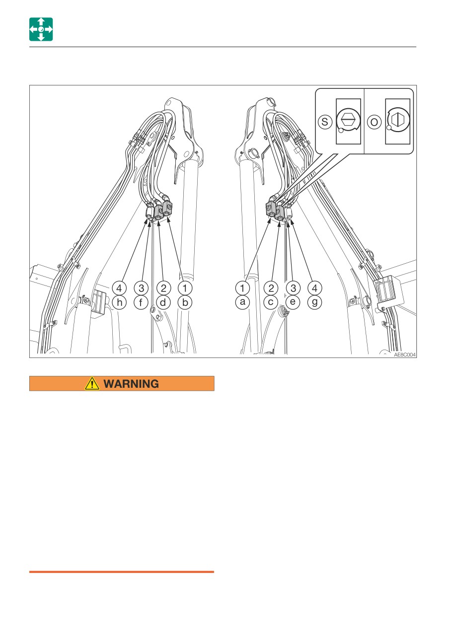
AUXILIARY HYDRAULIC LINES (IF EQUIPPED)
These lines deliver the hydraulic oil necessary
for operating a hydraulic breaker, crusher or
Oil may spurt out if pipes disconnected
other attachments.
before releasing the pressure in the
hydraulic system.
(1)
First auxiliary hydraulic lines
• Immediately after the engine is stopped
(2)
Second auxiliary hydraulic lines
and while the safety lock lever is still in
(3)
Third auxiliary hydraulic lines
the unlock position, turn the starter
(4)
Fourth auxiliary hydraulic lines
switch to ON and press each auxiliary
hydraulic switch several times to
Stop valve
release the pressure from the auxiliary
(S) : Closed
hydraulic circuit.
(O) : Open
• Press the air breather button to relieve
the tank pressure.
• When disconnecting hoses, stand to the
side and loosen them slowly to
gradually release the internal pressure
before removing.
2-70
CONTROLS
ACCESSORIES
Connecting the hydraulic circuits
Disconnecting the hydraulic circuits
To connect the attachment hydraulic lines,
1. Release the pressure remaining in the
observe the following procedures:
lines, and then close the stop valve.
1. Release the pressure remaining in the
Refer to “Releasing the residual pressure”
lines, and then close the stop valve.
on page 2-72.
Refer to “Releasing the residual pressure”
2. Disconnect the lines from the ports (a/c)
on page 2-72.
and (b/d).
2. Remove the plugs.
3. Install the plugs.
3. Connect the attachment hydraulic lines to
ports (a/c) and (b/d). When installing a
hydraulic breaker, connect the supply
circuit to the port (a) and the return circuit
to port (b).
4. Open the stop valves. When installing a
hydraulic breaker, open the selector valve
(1).
Refer to “Selector valve” on page 2-73.
5. When connecting is complete, purge air
from the hydraulic lines.
a. Start the engine and run it at a low idle
speed with no load for 10 minutes.
b. With the engine running in low idle,
operate the auxiliary hydraulic switches
repeatedly (approx. 10 times) to purge
air from the hydraulic lines.
c. Stop the engine and wait for at least 5
minutes until bubbles escape from the
hydraulic oil in the tank.
IMPORTANT: Follow the procedures for
purging air as instructed by the
attachment manufacturer, if applicable.
6. Check for oil leaks.
2-71
CONTROLS
ACCESSORIES
Operating
Releasing the residual pressure
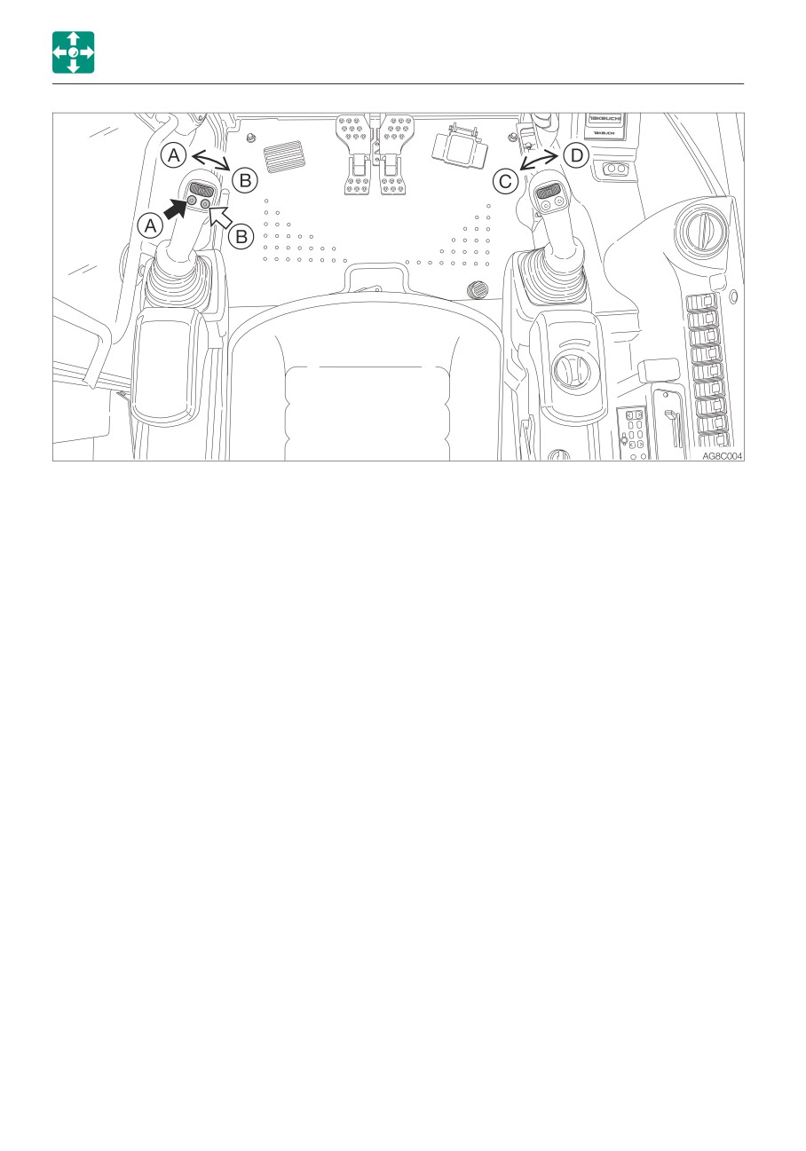
Press those buttons to control the flow of the
After the auxiliary hydraulic circuits have
oil in the first/second auxiliary hydraulic lines.
been used, pressure remains in the circuits.
(A)
Hydraulic oil flows to left auxiliary line
This is called the residual pressure. Release
(a).
this residual pressure before disconnecting
(B)
Hydraulic oil flows to right auxiliary line
the lines.
(b).
Perform the residual pressure releasing
(C)
Hydraulic oil flows to left auxiliary line
within 10 minutes after the engine stopping.
(c).
1. Park the machine on a flat, rigid and safe
(D)
Hydraulic oil flows to right auxiliary line
ground.
(d).
2. Stop the engine.
3. Lower the safety lock lever to the
unlocked position.
4. Turn the starter switch to the ON position.
5. Press the auxiliary hydraulic switches
several times to release the residual
pressure in the auxiliary hydraulic circuitry.
2-72
CONTROLS
ACCESSORIES
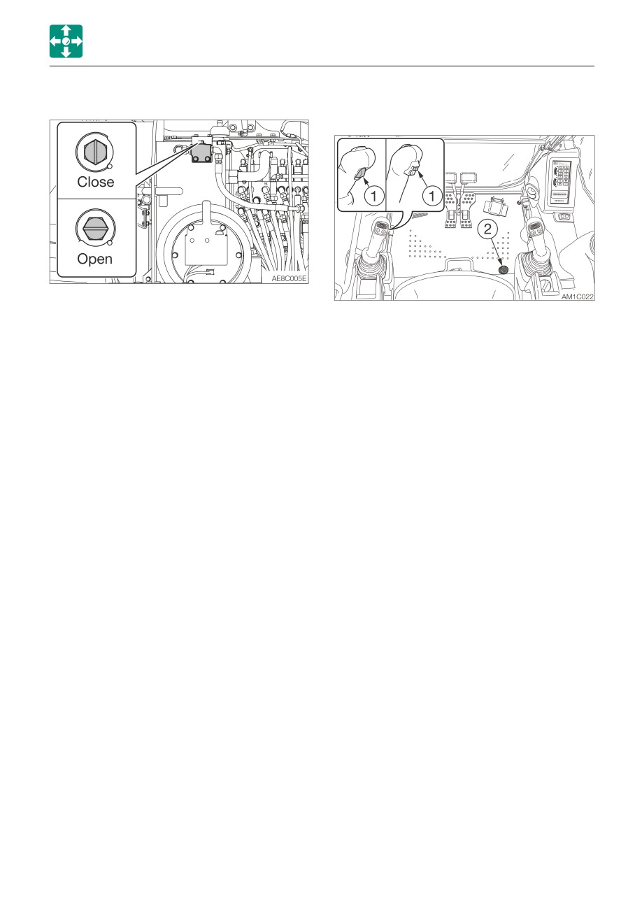
Selector valve
Third auxiliary hydraulic switch and
button (If equipped)
Open
When using a hydraulic breaker
(1-way flow)
The auxiliary 3rd is mainly used for the
Closed When using a reversible
attachment that can quickly connect/
attachment (2-way flow)
disconnect the bucket. After the engine is
Change the direction of the hydraulic oil flow
started, hydraulic oil constantly flows into the
by opening or closing the selector valve (1)
pipe (e). This allows the pressure in the (e)
inside the right side cover.
side to increase, preventing the pin inserted
For the machine with the auxiliary 1st auto
on the bucket from coming out. If the
tank switch, use the switch to select the
pressure in the (e) side drops, the warning
flow.
lamp starts flashing to warn that the bucket
Refer to “Auxiliary 1st auto tank switch (If
may come out. For a safety reason, the
equipped)” on page 2-54.
bucket can be disconnected only when the
button (1) and the switch (2) are pressed at
the same time. When they are pressed, the
hydraulic oil flows into the line (f) to increase
the pressure there. As the result, the pin on
the bucket comes out and the bucket is
removed from the machine.
• Bleeder unit for simultaneous use with
the auxiliary 1st and 2nd (if equipped)
Pressing both the auxiliary 3rd button (1)
and the switch (2) makes it possible to
release internal pressure from the auxiliary
3rd (e side), auxiliary 1st and auxiliary 2nd
at the same time. (The pressure is kept
drawn for six seconds after the button and
the switch are released.) This enables
faster attachment change.
2-73