Takeuchi Hydraulic Excavator TB175W (S/N 17540001~). WORKSHOP MANUAL - page 5
 

  Index      Manuals     Takeuchi Hydraulic Excavator TB175W (S/N 17540001~). WORKSHOP MANUAL


Search            copyright infringement  


Content      ..     3      4      5      6     ..


Takeuchi Hydraulic Excavator TB175W (S/N 17540001~). WORKSHOP MANUAL - page 5


MACHINE CONFIGURATION

CONTROl SYSTEM

III-26

TB175W

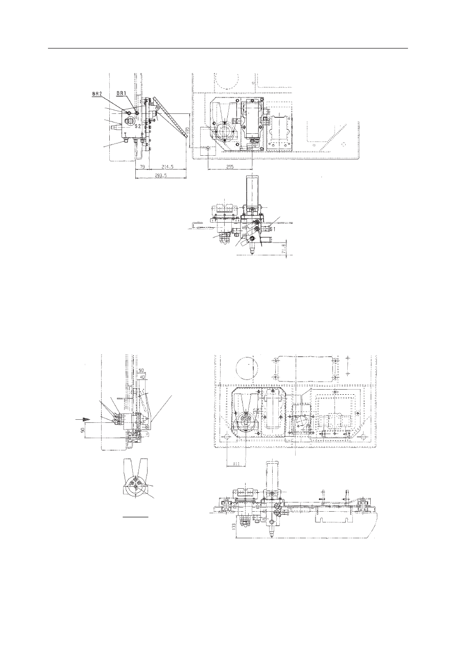
Pilot Valve (Brake)

  1.  Pilot Valve (Brake)
  2.  Adapter

  3.  Elbow
  4.  Adapter

Pilot Valve (Travel)

  1.  Pilot Valve (Travel)
  2.  Bushing

  3.  Elbow
  4.  Elbow

W2C510

2
1

2

3

3

4

2

W2C511E

2

1

4

3

VIEW A

2, 4

2, 3

A

III-27

MACHINE CONFIGURATION

ATTACHMENTS

TB175W

ATTAChMEnTS

ConSTrUCTIon

2-Piece Boom 1

1. Boom
2. Bushing
3. Dust Seal
4. Intermediate Boom
5. Plate
6. Protector
7. Clamp
8. Cover
9. Wire Harness

10. Rubber
11. Bracket

12. Pin
13. Pin
14. Pin
15. Pin
16. Shim
17. Grease Nipple
18. Boom Light
19. Bulb
20. Boom Cylinder
21. Arm Cylinder
22. Boom adjustment Cylinder

23. Shim
24. O-ring
25. Pin
26. Pin
27. Shim
28. Protector
29. Pin
30. Plate
31. Grease Nipple
32. Elbow
33. Elbow

34. Tube
35. Tube
36. Clamp
37. Band
38. Band
39. Cap

A:  

26 N·m

B:  

31.5 ±5.88 N·m

• Keep  the  clearance  at  the  pin  connecting  section

(excluding the bucket connecting section) to 0.5 mm 
or less by using the shim.

• When fastening the lock bolt with double nuts, main-

tain  a  clearance  between  the  nuts  and  the  bushing 
of 0.5~1.0 mm when tightening the double nuts.

:&

III-28

MACHINE CONFIGURATION

ATTACHMENTS

TB175W

2-Piece Boom 2

1. Pipe L
2. Pipe R
3. Clamp
4. Hose
5. Pipe
6. Hose
7. Clamp
8. Adapter
9. Pipe R

10. Pipe L
11. Pipe
12. Cap
13. Grease Nipple
14. Hose
15. Hose
16. Hose
17. Cap

• Keep  the  clearance  at  the  pin  connecting  section

(excluding the bucket connecting section) to 0.5 mm
or less by using the shim.

• When fastening the lock bolt with double nuts, main-

tain  a  clearance  between  the  nuts  and  the  bushing
of 0.5~1.0 mm when tightening the double nuts.

:&

III-29

MACHINE CONFIGURATION

ATTACHMENTS

TB175W

Mono-Boom

1. Boom
2. Bushing
3. Dust Seal
4. Cover
5. Plate
6. Protector
7. Pipe R
8. Pipe L
9. Pipe

10. Wire Harness

11. Rubber
12. Bracket
13. Clamp
14. Clamp
15. Pin
16. Pin
17. Pin
18. Pin
19. Pin
20. Shim

21. Adapter
22. Grease Nipple
23. Boom Light
24. Bulb
25. Boom Cylinder
26. Arm Cylinder
27. Hose
28. Hose
29. O-ring
30. Tube

31. Tube
32. Protector
33. Gauge
34. Plate
35. Cap
36. Band
37. Band
38. Band

A:  

26 N·m

B:  

31.5 ±5.88 N·m

• Keep  the  clearance  at  the  pin  connecting  section

(excluding the bucket connecting section) to 0.5 mm 
or less by using the shim.

• When fastening the lock bolt with double nuts, main-

tain  a  clearance  between  the  nuts  and  the  bushing 
of 0.5~1.0 mm when tightening the double nuts.

III-30

MACHINE CONFIGURATION

ATTACHMENTS

TB175W

Arm

1. Arm
2. Bushing
3. Bushing
4. Dust Seal
5. Dust Seal
6. Bucket Link
7. Bushing
8. Bushing
9. Dust Seal

10. Guide Link L
11. Guide Link R

12. Pin
13. Pin
14. Pin
15. Pin
16. Pin
17. Grease Nipple
18. Elbow
19. Elbow
20. O-ring
21. Bucket Cylinder
22. Hose

23. Shim
24. Shim
25. Shim
26. Cap
27. Gauge
28. Plate
29. Cap
30. O-ring
31. Elbow

A: 

26 N·m

• Keep  the  clearance  at  the  pin  connecting  section

(excluding the bucket connecting section) to 0.5 mm 
or less by using the shim.

• When fastening the lock bolt with double nuts, main-

tain  a  clearance  between  the  nuts  and  the  bushing 
of 0.5~1.0 mm when tightening the double nuts.

III-31

MACHINE CONFIGURATION

ATTACHMENTS

TB175W

InSPECTIon AnD ADjUSTMEnT

Adjusting the Clearance Between the Buck-
et and Arm

Adjust the clearance between the bucket and arm so 
that it is 0.5 mm.

1.  Clean  the  bucket  mount  and  the  area  around  it 

thoroughly.

2.  Slide the O-ring (1).

3.  Measure the clearance (X).

•  The opposite side (Y) should be fitting tight

-

ly with no clearance.

4.  Calculate  the  amount  of  the  clearance  adjust-

ment  (the  number  of  shims  which  need  to  be 
moved).
•  Subtract  the  recommended  clearance,  0.5 

mm  from  the  value  calculated  above  [clear-
ance  (X)].  However,  since  the  thickness  of 
the  adjustment  shims  is  0.5  mm,  the  actual 
clearance will be a value near 0.5.

  Example: If the clearance (X) is 1.8 mm,
   

1.8 – 0.5 = 1.3 mm


Shims to be moved: 2 shims

5.  Loosen the bolts (2), leave one and take out the 

other 2.

6.  With  the  bolt  remaining  in  the  end  plate  (3), 

flange (4) and shim (5), remove the parts so that 

their assembly order is not destroyed.

7.  Take out only the number of shims required for 

clearance adjustment from between the bushing 

(6) and flange.

8.  Insert  the  shims  which  were  just  removed  be-

tween the flange and the end plate, then reas

-

semble the parts.


Tighten the 3 bolts uniformly.

Bolt: 83 N·m

9.  Return the O-ring to its proper position.

MACHINE CONFIGURATION

HydRAUlIC SySTEM

III-35

TB175W

CONSTRUCTION

Hydraulic Tank

1. Tank
2. Air Breather
3. Cover
4. Cover
5. Spring
6. Filter Element
7. Check Valve
8. Suction Filter
9. O-ring

10. O-ring
11. Sight Gauge
12. Plug
13. O-ring
14. Check Valve
15. Snap Ring
16. Adapter
17. Washer
18. Bushing

A: 

 54.9 N·m

Apply thread-locking compound.

:&(

III-36

MACHINE CONFIGURATION

HydRAUlIC SySTEM

TB175W

Bleeding the air
IMPORTANT: After  replacing  the  hydraulic  oil, 
bleed the air from the hydraulic circuit and hy-
draulic  devices.  Failure  to  do  so  may  damage 
the hydraulic devices.

Hydraulic pump

1.  Open the engine hood.

2.  Disconnect the drain hose (1) from the hydrau-

lic pump.

3.  Once hydraulic oil overflows from the elbow (2), 

connect the drain hose (1).

Slew motor

1.  Loosen the bolts and remove the center cover (1).

2.  Remove the plug (2).

3.  Once  hydraulic  oil  overflows  from  the  plug 

hole, tighten the plug (2).

4.  Install the center cover (1).

Cylinders

1.  Start  the  engine  and  run  it  at  low  idle  for  10 

minutes.

2.  Set  the  engine  to  a  low  idle,  then  extend  and 

contract all the cylinders 4 or 5 times, without 

going to the stroke end.

3.  Run the engine at high speed, then extend and 

contract all the cylinders 4 or 5 times, without 

going to the stroke end.

4.  Set the engine back to a low idle, then extend 

and contract all the cylinders 4 or 5 times to the 
stroke ends.

W2C705

1

2

W2C706

1

2

MACHINE CONFIGURATION

ELECTRICAL SYSTEM

III-41

TB175W

1. Wire Harness
2. Short Connector
3. Cap
4. Wire Harness
5. Diode (3A yellow)
6. Plate
7. Resistor
8. Detector

:&

9. Relay

10. Controller
11. Flasher Relay
12. Box
13. Buzzer
14. Fuse Box
15. Bracket
16. Hour Meter

a:  Horn relay
b:  Wiper relay
c:  Light relay
d:  Lift alarm relay
e:  Parking light relay
f:  Head light relay
g:  Change speed relay
h:  Hazard relay

MACHINE CONFIGURATION

ELECTRICAL SYSTEM

III-42

TB175W

 W3C802

a

a

b

b

c

b

c

17540001~17540134

17540001~17540134

17540135~

2

17540001~17540094

6

2

5

3

4

9

1

7

10

8

  1.  Wire Harness
  2.  Fusible Link
  3.  Short Connector
  4.  Diode (3A yellow)
  5.  Short Connector
  6.  Wire Harness
  7.  Wire Harness
  8.  Diode (3A yellow)
  9.  Guard
 10. Horn

MACHINE CONFIGURATION

ELECTRICAL SYSTEM

III-43

TB175W

:&

/(9(5/,1.

/(9(56:,7&+$1'/,0,76:,7&+

III-44

MACHINE CONFIGURATION

ELECTRICAL SYSTEM

TB175W

:&

MACHINE CONFIGURATION

AIR CONdITIONER SYSTEM

III-45

TB175W

Air CondiTioner sysTem

ConsTruCTion

Compressor  Assembly

  1.  Bracket
  2.  Guard
  3.  Shaft
  4.  Collar
  5.  Compressor
  6.  Pulley
  7.  Hose

  8.  Hose
  9.  Bushing
10.  Valve
11.  Adaptor
12.  Bushing
13.  Elbow
14.  V-Belt

A: Allow a clearance.

B: Press  on  the  center  of  the  belt  with  a  finger.  The 

belt’s tension is normal if it bends about 8 mm when 
pressed with a force of about 98N.

 W3C805

9

11

13

10

12

14

7

8

2

5

3

1

4

6

B

A

1mm


Content      ..     3      4      5      6     ..