Takeuchi Hydraulic Excavator TB175W (S/N 17540001~). WORKSHOP MANUAL - page 3
 

  Index      Manuals     Takeuchi Hydraulic Excavator TB175W (S/N 17540001~). WORKSHOP MANUAL


Search            copyright infringement  


Content      ..     1      2      3      4      ..


Takeuchi Hydraulic Excavator TB175W (S/N 17540001~). WORKSHOP MANUAL - page 3


II-16

SPECIFICATIONS

STANDARDS FOR JUDGING PERFORMANCE

Dozer Blade

Measuring Method

•  Engine 

: Maximum r.p.m.

•  Hydraulic Oil Temp.  : 50~60°C

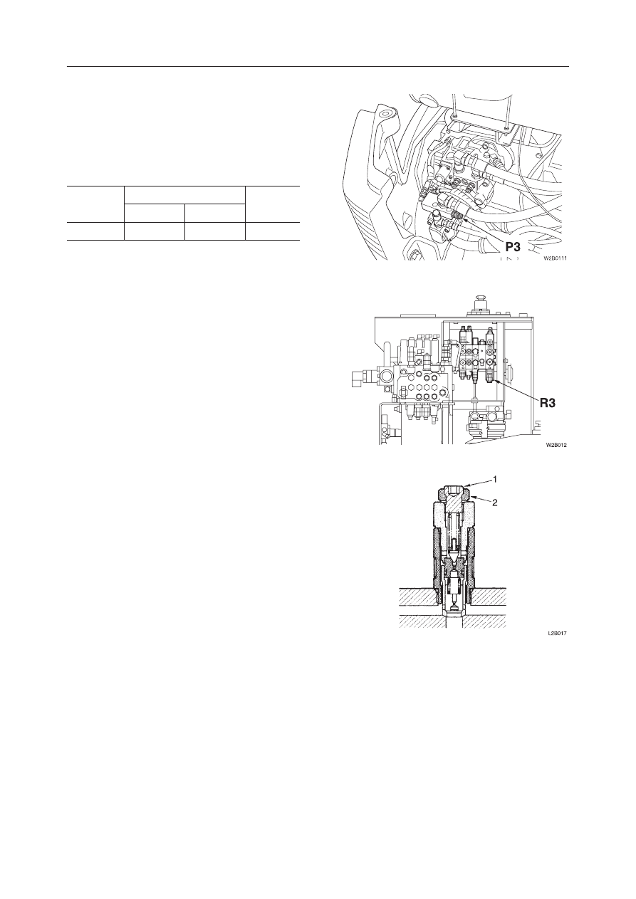
•  Mount the pressure gauge on the pressure detec-

tion port, operate the desired hydraulic circuit and 

measure the relief pressure.

Adjusting Method

1.  Loosen locknut (2), then begin adjusting pres-

sure by turning setting screw (1).


Turning clockwise ................ raises the set pressure.


Turning counterclockwise .... lowers the set pressure.

2.  In order to keep the setting screw from turning 

after  pressure  has  been  adjusted,  tighten  the 

locknut while at the same time holding the set-

ting screw firmly in place.

3.  Operate the relief valve once more to confirm 

that the pressure that has been set it stabilized.

Circuit

Pressure Detection Port

Relief 

Valve

Port Position

Size

Dozer Blade

P3

G1/4

R3
II-17

SPECIFICATIONS

STANDARDS FOR JUDGING PERFORMANCE

Hydraulic Oil Pressure (Slewing Relief Valve 

Set Pressure)

Measuring Method

•  Engine 

: Maximum r.p.m.

•  Hydraulic Oil Temp.  : 50~60°C

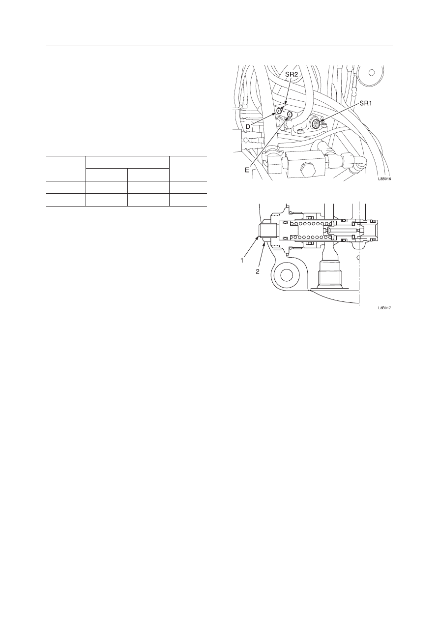
•  Mount  the  pressure  gauge  on  the  pressure  de-

tection  port  and  set  a  solid  obstacle  so  that  the 

upperstructure cannot slew in the direction to be 

measured.  Next,  operate  the  circuit  to  be  mea-

sured and measure the relief pressure.

Adjusting Method

1.  Loosen locknut (2), then begin adjusting pres-

sure by turning setting screw (1).


Turning clockwise ................ raises the set pressure.


Turning counterclockwise .... lowers the set pressure.

2.  In order to keep the setting screw from turning 

after  pressure  has  been  adjusted,  tighten  the 

locknut while at the same time holding the set-

ting screw firmly in place.

3.  Operate the relief valve once more to confirm 

that the pressure that has been set it stabilized.

Circuit

Pressure Detection Port

Relief 

Valve

Port Position

Size

Right Slew

D

G1/4

SR1

Left Slew

E

G1/4

SR2

II-18

SPECIFICATIONS

STANDARDS FOR JUDGING PERFORMANCE

Hydraulic  Oil  Pressure  (Pilot  Relief  Valve 

Set Pressure)

Measuring Method

•  Engine 

: Maximum r.p.m.

•  Hydraulic Oil Temp.  : 50~60˚C

•  Mount pressure gauge on the pressure detection 

port and measure the pilot relief pressure.

Pressure Adjustment

The relief valve pressure is set at the factory. Do not 

adjust it unless necessary.

1.  Remove  the  cap  screws,  and  then  remove  the 

cover (1).

2.  Remove the spring (2) and the plunger (3).

3.  Adjust the pressure with the shims (4)


Shim thickness ..........0.2 mm


Shim thickness ..........0.5mm

4.  Upon  completion  of  the  pressure  adjustment, 

assemble  the  relief  valve  and  confirm  that  the 

relief valve set pressure is stable.

 Cap Screw: 3.92 N·m

Hydraulic Oil Pressure (Steering Relief Valve 

Set Pressure)

Measuring Method

•  Engine 

: Maximum r.p.m.

•  Hydraulic Oil Temp.  : 50~60˚C

•  Mount pressure gauge on the pressure detection 

port and measure the pilot relief pressure.

Pressure Detection Port

Relief Valve

Port Position

Size

P4

G1/4

––

0.2 mm Remove Decrease of approx. 0.13 MPa

Add

Increase of approx. 0.13 MPa

0.5 mm Remove Decrease of approx. 0.31 MPa

Add

Increase of approx. 0.31 MPa

Pressure Detection Port

Relief Valve

Port Position

Size

P5

G1/4

PR

II-19

SPECIFICATIONS

STANDARDS FOR JUDGING PERFORMANCE

Slew Time

•  Engine 

: Maximum r.p.m.

•  Hydraulic Oil Temp.  : 50~60°C

•  Measurement Posture : Completely  retract  the 

arm cylinder, fully extend the bucket cylinder and 

adjust so that boom foot pin and bucket pin are 

at matching height. Rest the dozer blade on the 

ground.

•  With the hoe attachment in a no-load state, wait 

1 rotation, then measure the time required for the 

next 2 rotations.

Overrun When Slewing Stops

•  Engine 

: Maximum r.p.m.

•  Hydraulic Oil Temp.  : 50~60°C

•  Measurement Posture : Same as that for measur-

ing slew time.

•  Draw  matching  marks  on  the  outer  race  of  the 

slew bearing and lower frame at an exactly 180 

degrees rotation from the starting point. With the 

hoe attachment in a  no-load state, rotate 180 de-

grees  at,  which  point  return  the  operation  lever 

to neutral. Measure the differential between the 

position marks and the point the hoe attachment 

stops.

Natural Slew Drop

•  Engine 

: Stopped

•  Hydraulic Oil Temp.  : 50~60°C

•  Grade 

: 15°

•  Measurement Posture : Same as that for measur-

ing slew time.

•  Rotate the upper machinery so that it is directly 

abeam of the grade, then draw positional marks 

on  the  slew  bearingʼs  outer  race  and  the  lower 

frame. Then measure the distance that develops 

between the marks after 5 minutes.

Boom Cylinder Speed

•  Engine 

: Maximum r.p.m.

•  Hydraulic Oil Temp.  : 50~60°C

•  Measurement Posture : Completely  retract  the 

arm cylinder, fully extend the bucket cylinder and 

rest the dozer blade on the ground.

•  Then measure the time required for the bucket to 

reach  its  highest  elevation  point  (lowest  point) 

from its lowest point (highest point) resting on the 

ground. (Do not include the cushioning time.)

II-20

SPECIFICATIONS

STANDARDS FOR JUDGING PERFORMANCE

Arm Cylinder Speed

•  Engine 

: Maximum r.p.m.

•  Hydraulic Oil Temp.  : 50~60°C

•  Measurement Posture : Completely  retract  the 

arm  cylinder,  fully  extend  the  bucket  cylinder, 

position the arm horizontally and rest the dozer 

blade on the ground.

•  Then measure the time required for the arm cyl-

inder to completely retract (extend) from a fully 

extended state (retracted state).

Bucket Cylinder Speed

•  Engine 

: Maximum r.p.m.

•  Hydraulic Oil Temp.  : 50~60°C

•  Measurement Posture : Completely  retract  the 

arm  cylinder,  position  the  arm  horizontally  and 

rest the dozer blade on the ground.

•  Then  measure  the  time  required  for  the  bucket 

cylinder  to  completely  retract  (extend)  from  a 

fully extended state (retracted state).

Dozer Blade Cylinder Speed

•  Engine 

: Maximum r.p.m.

•  Hydraulic Oil Temp.  : 50~60°C

•  Measurement Posture : Using the hoe attachment, 

lift up the dozer blade end of the excavator.

•  Then, raising and lowering the dozer blade full 

stroke,  measure  the  time  required  per  stroke  in 

each direction.

Swing Cylinder Speed

•  Engine 

: Maximum r.p.m.

•  Hydraulic Oil Temp.  : 50~60°C

•  Measurement Posture : Same as that for measur-

ing slew time.

•  While  swinging  the  boom  left  (right)  to  right 

(left), measure the time required for a full stroke 

each way.

  (Do not include the cushioning time.)

II-21

SPECIFICATIONS

STANDARDS FOR JUDGING PERFORMANCE

Adjust Cylinder Speed

•  Engine 

: Maximum r.p.m.

•  Hydraulic Oil Temp.  : 50~60°C

•  Measurement Posture : Completely  retract  the 

arm cylinder, fully extend the bucket and boom 

cylinders, position the arm horizontally and rest 

the dozer blade on the ground.

•  Then measure the time required for the adjust cyl-

inder to completely retract (extend) from a fully 

extended state (retracted state).

Natural Cylinder Drop

Boom, Arm, Bucket, Dozer Blade, Bucket Tip

•  Engine 

: Maximum r.p.m.

•  Hydraulic Oil Temp.  : 50~60°C

•  Measurement Posture : Completely  retract  the 

dozer blade and arm cylinders, fully extend the 

bucket cylinder and adjust the bucket pin position 

to the same height as the boom foot pin.

•  Maintain this position for 10 minutes, then mea-

sure the change in rod length and the distance the 

bucket tip falls.

Swing Cylinder

•  Engine 

: Stopped

•  Hydraulic Oil Temp.  : 50~60˚C

•  Grade 

: 15˚

•  Measurement Posture : Same as that for measur-

ing slew time.

•  Rotate the upper machinery so that it is directly 

abeam of the grade, then measure the change in 

rod length after 5 minutes.

II-22

SPECIFICATIONS

STANDARDS FOR JUDGING PERFORMANCE

III-

TB175W

III .

  MACHINE  CONFIGURATION

III-

MACHINE CONFIGURATION

TB175W

CONTENTS

Drive System ...........................................................................................................................................................3

Slew System ............................................................................................................................................................9

Travel System ....................................................................................................................................................... 11

Upper Frame .........................................................................................................................................................13

Control System......................................................................................................................................................21

Attachments ..........................................................................................................................................................27

Hydraulic System ..................................................................................................................................................33

Electrical System ..................................................................................................................................................37

Air Conditioner System ........................................................................................................................................44

MACHINE CONFIGURATION

DRIVE SYSTEM

III-

TB175W

  1.  Engine Foot FL
  2.  Engine Foot FR
  3.  Engine Foot RL
  4.  Engine Foot RR
  5.  Stopper
  6.  Stopper
  7.  Cushion Rubber
  8.  Cushion Rubber

  9.  Ground Cable
10.  Bracket
11.  Exhaust Pipe
12.  Pipe
13.  Bracket
14.  Silencer
15.  Gasket
16.  Gasket

B: 

 4 N·m

C: 

 9 N·m

D: 

 55 N·m


Apply thread-locking compound.

E: “A” Mark
F: 

  N·m

G: 

 .9 N·m

III-

DRIVE SYSTEM

CONSTRUCTION

Engine Mount 1/2

:&(

$

$

*

'

'

(

(

%

&

%
&

(

(

%
&

%
&

'

)

)


MACHINE CONFIGURATION

DRIVE SYSTEM

III-4

TB175W

Engine Mount 2/2

A: 

 .9 N·m

A: 

 4.9 N·m

  1.  Bracket
  2.  Air Cleaner
  3.  Hose
  4.  Hose
  5.  Pipe
  6.  Pipe
  7.  Pipe
  8.  Pipe
  9.  Hose
10.  Hose
11.  Drain Vave 

12.  Hose
13.  Hose
14.  Hose
15.  Sub Tank
16.  Bracket
17.  Plate
18.  Hose
19.  Sensor
20.  Joint
21.  Hose

III-4

:&(

$

$

*

'

'

(

(

%

&

%
&

(

(

%
&

%
&

'

)

)


MACHINE CONFIGURATION

DRIVE SYSTEM

III-5

TB175W

III-5

Radiator and Oil Cooler

1. Stay
2. Stay
3. Shroud
4. Plate
5. Plate
6. Plate
7. Net

8. Bracket
9. Bracket

10. Guard
11. Cushion Rubber
12. Radiator

 and 

Oil Cooler

13. Cushion Rubber
14. Guard

:&(

MACHINE CONFIGURATION

DRIVE SYSTEM

III-

TB175W

Pump Coupling

1. Engine Housing
2. Hydraulic Pump
3. Hab
4. Gear Pump

A: Supply molybdenum disulfide grease.

B: 

 8 N·m

C: 

 54.9 N·m

D: 

 55.8 N·m

Travel, Bucket, Boom[1], Arm[2]

Travel, Auxiliary, Boom[2], Arm[1], Swing

Outrigger, Slew, Auxiliary

Steering, Brake

Pilot Pressure

P1

P2

P3

P4

P5

The  pump  coupling  connects  the  engine  flywheel 

and the hydraulic pump’s drive shaft. It is construct-
ed so that it absorbs vibrations, torsions, impact and 
out of center of the engine and hydraulic pump.

• Refer  to  the  table  concerning  the  responsibility

of  each  of  the  pumps  shown  in  the  drawing  at
right.

III-

:&

W2C104

P1

P2

P3 P4

P5

MACHINE CONFIGURATION

DRIVE SYSTEM

III-8

TB175W

Fuel Supply Pump

A: 

 0.8 N·m

B: “Red” Mark

1. Box
2. Resistor
3. Switch
4. Relay
5. Wire Harness
6. Diode (3A, yellow)
7. Hose

8. Hose
9. Plug

10. Level Switch
11. Strainer
12. Pump
13. Float

III-8

C:Upon  assembling,  inspect  the  continuity  using  a 

tester when the level switch float (13) is at ON and 

OFF positions.

Float is at OFF (upper) position There is no continuity.

Float is at ON (upper) position There is no continuity.

:&


Content      ..     1      2      3      4      ..