Takeuchi Hydraulic Excavator TB175W (S/N 17540001~). WORKSHOP MANUAL - page 2
 

  Index      Manuals     Takeuchi Hydraulic Excavator TB175W (S/N 17540001~). WORKSHOP MANUAL


Search            copyright infringement  


Content      ..      1      2      3      ..


Takeuchi Hydraulic Excavator TB175W (S/N 17540001~). WORKSHOP MANUAL - page 2


I-14

GENERAL

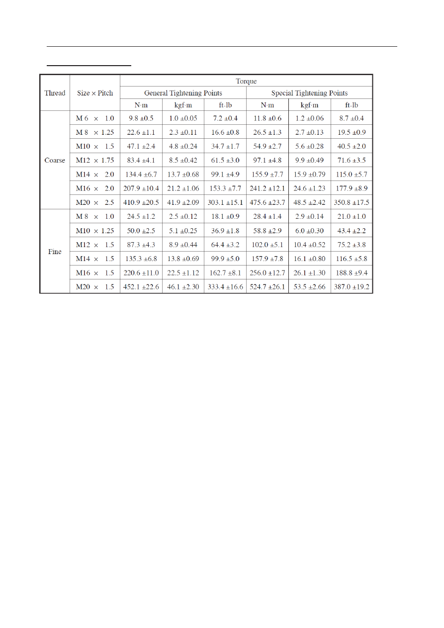
Bolts and Nuts (for ISO Strength Category 10.9)

1. General Tightening Points (Non-lubricated)

• All  securing  points  other  than  the  special

tightening points.

2. Special Tightening Points (Grease with molyb-

denum disulfide applied.)

• Points  where  particularly  necessary  due  to

function.

Special  tightening  positions  and  associated

instructions are given in the text.

3. Points where thread-locking compound is used

(Three Bond #1324 is applied.)

Thread-locking compound positions and associ-

ated instructions are given in the text.

4. If tightening torque values are provided in this

manual, then tightening should be done accord-

ing to those values.

(This indicates that the tightening torque differs

from the values given in this table.)

5. In order to tighten bolts and nuts evenly, they

should be tightened alternately top, bottom, left,

right.

II-1

II .  

SPECIFICATIONS

II-2

SPECIFICATIONS

In regard to Standard Values and Allowable Values

The terms used in the items “Servicing Standards” and “Standards for Judging Performance” have the following 
meanings.

Standard Value ............ This indicates the standard value for the new machine at the time of shipping from the 

factory. It should be used as the target value for maintenance work after operation.

Allowable Value .......... The dimensions of parts change during use because of wear and deformation. Also, the 

performance  of  pumps,  motors,  and  other  hydraulic  equipment  drops,  and  this  is  the 
estimated value indicating the use limit for the respective part. It is decided under refer-
ence to the standard at the time of shipping, the results of various tests, etc. As the use 
conditions, the degree of repairs, etc., differ for each machine, these should be combined 
and used as reference for servicing standards and standards for judging performance.
* Do  not  use  the  standard  values  and  the  allowable  values  as  standards  for  customer

claims.

CONTENTS

Names of C

3

D

4

Specifications

 T

6

Recommended Lubricants

12

Standards for Judging Performance ......................................................................................................................

 ......................................................................................................................

 ......................................................................................................................

 ......................................................................................................................

 ......................................................................................................................

 ......................................................................................................................

........................

..............

..............

..............

..............

 ............................................................................................................................................................

14

Reference Value Table

14

Methods for Inspecting Performance .............................................................................................................

 ..........................................................................................................................................

15

Hydraulic Circuit Diagram

23

Electrical Wiring Diagram

25

II-3

SPECIFICATIONS

NAMES OF COMPONENTS

1. Cab

2. Engine Hood

3. Fuel Tank

4. Hydraulic Tank

5. Hydraulic Pump

6. Slew Motor

7. Pilot Valve

8. Battery

9. Control Valve

10. Axle Lock Cylinder

11. Engine

12. Tire

13. Axle

14. Hub

15. Swing Cylinder

16. Undercarriage

17. Dozer Blade

18. Steering Wheel

19. Dozer Blade Cylinder

20. Swivel Joint

21. Bucket

22. Bucket Cylinder

23. Arm

24. Arm Cylinder

25. Boom

26. Boom Cylinder

27. Swing Bracket

NAMES OF COMPONENTS

II-4

SPECIFICATIONS

DIMENSIONS

DIMENSIONS

2-Piece Boom

Machine Dimensions

Operating Range

Unit: mm

2-Piece Boom Mono-Boom

A

6260

6320

B

2110

C

2925

D

1720

E

1715

F

2100

G

2330

H

2300

J

515

K

335

L

2505

2620

M

1955

2060

N

2385

2495

P

690

Q

730

R

1815

S

600

T

4380

4445

U

2895

2645

V

80°

W

50°

Unit: mm

2-Piece Boom

A

7650

B

7430

C

4085

D

3600

E

8325

F

6355

G

2665

H

4360

J

335

K

145

II-5

SPECIFICATIONS

Mono-Boom

DIMENSIONS

Operating Range

Unit: mm

Mono-Boom

A

6945

B

6700

C

4055

D

3220

E

6780

F

4765

G

1330

H

4270

J

335

K

145

II-6

SPECIFICATIONS

SPECIFICATIONS TABLES

SPECIFICATIONS

SPECIFICATIONS TABLES

Serial Number

17540095 or later

Machine Type

2-Pice Boom

Mono-Boom

Machine Mass (not including operator)

kg

8130

7905

Engine Rated Output

kW/min

–1


49.3/2300

Bucket Capacity (Standard Bucket)

Rated Capacity

m

3

0.245

Struck Capacity

m

3

0.185

Performance

Slew Speed: Slow Speed

min

–1


4.1 to 7.6

Normal Speed

min

–1

10.7

Travel Speed:

Forward: Creep

km/h

0 to 4.5

Site

km/h

0 to 9.0

Road

km/h

0 to 20

Reverse: Creep

km/h

0 to 4.5

Site

km/h

0 to 9.0

Road

km/h

0 to 20

Gradeability

% (degree)

70 (35)

Minimum Turning Radius

mm

5855

Minimum Turning Clearance Radius

mm

5615

Noise Level: Sound-power level

dB (A)

L

WA


99

Sound-pressure level

dB (A)

L

PA

 77

Auxiliary Hydraulic Flow Rate

1st

L/min

69

2nd

L/min

53.6

3nd

L/min

11.3

Dimensions

Overall Length

mm

5685

Overall Width

mm

2330

Overall Height

mm

3990

Dimensions of Base Machine

Tail Swing Radius

mm

1720

Distance of Rearmost Upper Structure from Axis of Rotation

mm

1715

Clearance Height under Upperstructure

mm

1140

Wheel Base

mm

1815

Rear Overhang

mm

765

Minimum Ground Clearance

mm

335

II-7

SPECIFICATIONS

STANDARDS FOR JUDGING PERFORMANCE

II-8

SPECIFICATIONS

SPECIFICATIONS OF DEVIDES

SPECIFICATIONS TABLES

Serial Number

17540095 or later

Engine

Model

Yanmar 4TNV98T-ZSTBW

Type

4-cycle, vertical, water-cooled, in-line, 4-cylinder diesel engine

Number of Cylinders – Bore × Stroke

mm

4-98 

×

 110

Total Displacement

mL

3318

Compression Ratio

18

Performance

Maximum Torque

N·m/min

-1

271.3 to 295.8/1650 ±100

Maximum No-load R.P.M.

min

–1


2350 ±10

Minimum No-load R.P.M.

min

–1

1100 ±10

Specific Fuel Consumption

g/kW·h

<249

Starter

V – kW

12 – 3.0

Generator

V – kW

12 – 0.96

Battery

V – A·h

12 – 90

Hydraulic Pump

Model

K3SP36C-1CFR-9002-2

Type

Variable displacement type double axial piston

Delivery:

P1

L/min

72.6

P2

L/min

72.6

Rated Pressure: P1

MPa

27.4/31.0*

P2

MPa

27.4/31.0*

Hydraulic Pump (Gear)

Model

SDYA259.5F1H1-R473

Type

Double gear

Delivery:

P3

L/min

55.7

P4

L/min

20.9

Rated Pressure: P3

MPa

24.0

P4

MPa

17.5

Hydraulic Pump (Gear)

Model

GPW1-C-4A

Type

Gear

Delivery:

P5

L/min

10.8

Rated Pressure: P5

MPa

3.4

Control Valve (Mono-Block)

Model

KVMM-80-TB

Number of Circuits

Mono-Block

Main Relief Valve Pressure Setting

MPa

27.4/31.0*

Port Relief Valve Pressure Setting

MPa

33.3

MPa

20.6

*: In Case of raise

=

II-9

SPECIFICATIONS

SPECIFICATIONS TABLES

Control Valve (4-Section)

Model

KVSE31-4

Number of Circuits

4

Main Relief Valve Pressure Setting

MPa

24.0

Port Relief Valve Pressure Setting

MPa

26.9

MPa

20.6

Solenoid Valve

Model

16521-00010

Number of Solenoids

4

Solenoid Rated Voltage

V

12

Relief Valve Set Pressure

MPa

3.4

Solenoid Valve

Model

16545-00000

Number of Solenoids

3

Solenoid Rated Voltage

V

12

Solenoid Valve (2-Piece Boom)

Model

16522-00000

Number of Solenoids

4

Solenoid Rated Voltage

V

12

Proportional Control Solenoid

Model

2KWE5A-30/G12R-269

Number of Solenoids

2

Solenoid Rated Voltage

12

Pilot Valve

Model

PV48M2

Secondary Side Pressure (Ports 1, 3)

MPa

0.54 to 2.06

(Ports 2, 4)

MPa

0.64 to 1.86

Operating Angle: Single (Ports 1, 3)

degree

19

Single (Ports 2, 4)

degree

25

Pilot Valve (Swing)

Model

PV6P1013A

Secondary Side Pressure

MPa

0.49 to 2.06

II-10

SPECIFICATIONS

SPECIFICATIONS TABLES

Boom Cylinder

Bore Diameter 

×

 Rod Diameter

mm

120 × 75

Stroke

mm

725

Fully Retracted Length (Pitch)

mm

1207

Cushion Mechanism

Rod Side

Arm Cylinder

Bore Diameter 

×

 Rod Diameter

mm

100 × 65

Stroke

mm

875

Fully Retracted Length (Pitch)

mm

1327

Cushion Mechanism

Both Ends

Bucket Cylinder

Bore Diameter 

×

 Rod Diameter

mm

85 

×

 55

Stroke

mm

660

Fully Retracted Length (Pitch)

mm

1035

Cushion Mechanism

––

Boom Adjustment Cylinder

Bore Diameter 

×

 Rod Diameter

mm

90 × 55

Stroke

mm

580

Fully Retracted Length (Pitch)

mm

955

Cushion Mechanism

––

Slew Motor

Model

MSG-44P-21

Type

Piston Motor

Total Displacement

cm

3

/rev

702.4

Motor Displacement

cm

3

/rev

34.1

Redution Gear Ratio

1/20.615

Relief Valve Pressure Setting

MPa

23.5

Parking Brake Torque

N·m

177.9

Parking Brake Release Pressure

MPa

1.5

Travel Motor

Model

A6VM80HA1TA

Motor Displacement: Low

cm

3

/rev

80

Hi

cm

3

/rev

27.2

Front Axle

Type

212

Rear Axle

Type

112

Drop Box Type

357

Reduction Gear Ratio: Low

1:3.28

Hi

1:1.43

Reduction Gear

––

Differential

11.35

Hub

1:6.00

II-11

SPECIFICATIONS

Tire

Front Tire: Qty.

4

Size

8.25-20-12PR

Tire Pressure

kpa

600

Steering System

Type

Front Setting System

Operation Type

Hydraulically-Operated

Breake Device

Travel Brake Type

Front and rear wheel braking, direct acting hydraulic 

disk with brake lock

Parking Brake Type

Rear wheel braking disk

Outrigger (Option)

Type

Hinge

SPECIFICATIONS TABLES

II-12

SPECIFICATIONS

RECOMMENDED LUBRICANTS

Select the appropriate fuel, lubricant and grease according to the temperature by referring to the table below.

•  Regardless of the specified time, change the oil if it becomes too dirty or degraded.

•  When refilling, never mix oils of different brands. If a brand is to be changed, replace the whole fuel/oil.

*:  For water, use tap water (soft). Do not use well or river water.


When the ambient temperature drops below 0°C, add coolant (antifreeze). Follow the coolant manufacturerʼs 

instructions to determine the mixture ratio.

**: The replacement interval for hydraulic oil depends on the oil type being used. New machines are shipped 

from the factory with the Takeuchi genuine hydraulic oil 46. This manual describes when to replace the 

hydraulic oil assuming that this Takeuchi oil 46 is used. When a conventional antiwear hydraulic oil is used, 

replace it every 2000 hours.

Part

Type

Type by air temperature

     -20  -10     0    10    20    30   40°C

When to change/

replenish

Capacity

Engine oil pan Diesel engine oil

API: CF class

Every  250  hrs 

after the first 50 

hrs

Upper limit 10.2 L

Lower limit 5.7 L

SAE 10W-30

SAE 15W-40

Hydraulic  oil 

tank

Takeuchi  genuine 

hydraulic oil 46

Every 4000 hrs**

Total amount of 

oil: 135 L

Tank capacity:

68 L

ISO VG46

Anti-wear hydrau-

lic oil

Every 2000 hrs**

ISO VG32

ISO VG46

ISO VG68

Engine cooling 

system

Cooling water

(water + coolant)*

Every 1000 hrs 12.0 L

Mixture of 50% coolant

Mixture of 30% coolant

Hub

Gear oil

API: GL-4

SAE 90

Every 1500 hrs 1.0 L

Transmission

Gear oil

API: GL-4

SAE 90

Every 1500 hrs 1.3 L

Differential

Gear oil

API: GL-4

SAE 90

Every 1500 hrs 8.5 L

Undercarriage

Lithium grease

EP-2

NLGI No.2

––

Every 250 hrs

As required

Slew bearing

Every 50 hrs

Working equip-

ment

Daily or every

10 hrs

Levers

When required

RECOMMENDED LUBRICANTS

II-13

SPECIFICATIONS

RECOMMENDED LUBRICANTS

Diesel fuel standards

Use the diesel fuel that is compliant with any of the 
standards  below.  The  table  below  shows  the  stan-
dards from the various countries. 

Diesel fuel standards

Region

No. 2-D, No. 1-DASTM D975-94

USA

EN590:96

EU

Part

Type

Capacity

Fuel tank

Desel fuel

To keep the performance and service life of the engine, al-
ways use the clean and high-quality fuel.

  To avoid freezing in cold climates, use a light oil that still 

functions when the temperature is at least 12°C below the 
lowest expected ambient temperature.

  Use a light oil that has a cetane number of 45 or higher. 

When  operating  at  a  very  low  temperature  or  at  a  high 
altitude, a higher cetane number fuel will be required.

  The sulfur content must be less than 0.5% by volume. he 

recommended  value,  however,  is  less  than  0.05%.  The 
electronically-controlled  engine  with  an  EGR  system 
should use fuel containing less than 0.05% sulfur.

  Fuel containing a high content of sulfur may cause sulfu-

ric acid corrosion inside the cylinder. 

  Do not mix diesel fuel with any kerosene, used engine oil 

or leftover fuel.

  Poor quality fuel can degrade the engine performance. It 

also can damage the engine.

  Avoid  using  additives  to  fuel.  Some  fuel  additives  can 

degrade the engine performance. 

120 L

II-14

SPECIFICATIONS

STANDARDS FOR JUDGING PERFORMANCE

STANDARDS FOR JUDGING PERFORMANCE

REFERENCE VALUE TABLE

Serial Number

17540095 or later

Machine Type

2-Piece Boom

Mono-Boom

Item

Unit

Standard Values Allowable Values Standard Values Allowable Values

Hydraulic Oil Pressure

Travel

MPa

31.00

31.00

Boom

MPa

27.46

27.46

Arm

MPa

27.46

27.46

Dozer Blade

MPa

24.0

24.0

Slew

MPa

23.54

23.54

Pilot Pressure

MPa

3.43

3.43

Brake, Steering

MPa

17.16

17.16

Slew

Slew Time Normal Speed

s

10.82

10.82

Slow Speed

s

14.53

14.53

Overrun When Slewing Stops

mm

498.5

380

Natural Slew Drop

mm

0

0

Cylinders

Cylinder Speed

Boom

Extended

s

3.10

2.20

Retracted

s

3.65

2.65

Arm

Extended

s

3.43

3.43

Retracted

s

3.07

3.07

Bucket

Extended

s

3.36

3.36

Retracted

s

2.11

2.11

Dozer Blade

Extended

s

1.91

1.91

Retracted

s

1.46

1.46

Swing

Extended

s

8.38

8.1

Retracted

s

8.36

8.24

Adjust

Extended

s

7.81

––

Retracted

s

7.42

––

Cylinders

Natural Cylinder Drop

Boom

mm

3

2

Arm

mm

2

2

Bucket

mm

2

2

Dozer Blade

mm

0

0

Swing

mm

5

5

Adjust

mm

6

––

Bucket Tip

mm

100

60

Slew Bearing

Backlash

mm

30 ±10

30 ±10

II-15

SPECIFICATIONS

STANDARDS FOR JUDGING PERFORMANCE

METHODS  FOR  INSPECTING  PERFOR-

MANCE

Hydraulic  Oil  Pressure  (Main  Relief  Valve 

Set Pressure)

Travel, Boom, Arm

Measuring Method

•  Engine 

: Maximum r.p.m.

•  Hydraulic Oil Temp.  : 50~60°C

•  Mount the pressure gauge on the pressure detec-

tion port, operate the desired hydraulic circuit and 

measure the relief pressure.

Adjusting Method

Travel circuit (High pressure set)

1.  Loosen the lock nut (1).

2.  Fasten the plug (2) until the piston (3) contacts 

the surface A of the plug (4).

•  Be sure that the plug (4) does not turn together 

with the plug (2).

•  The  tightening  torque  of  the  plug  (2)  is 

19.6N·m or less.

•  The size B is 4 mm or more.

3.  Turn the plug (4) and adjust the set pressure.

•  Turn the plug slowly by referring to the pres-

sure gauge.

•  The  pressure  increases  by  21.3  MPa  at  one 

turn of the plug.

4.  Upon  completion  of  the  pressure  adjustment, 

hold the plug (4) to prevent it from turning and 

fasten it with the lock nut (5).

Boom and Arm Circuits (Low pressure set)

5.  First,  set  the  travel  circuit  (high  pressure  set), 

then loosen the plug (2) and adjust the set pres-

sure.

•  Turn the plug slowly by referring to the pres-

sure gauge.

•  The pressure decreases by 21.3 MPa at one 

turn of the plug

6.  Upon  completion  of  the  pressure  adjustment, 

hold the plug (2) to prevent it from turning and 

fasten it with the lock nut (1).

7.  Actuate the relief valve again and confirm that 

the set pressure is stable.

Circuit

Pressure Detection Port

Relief 

Valve

Port Position

Size

Boom

P1

G1/4

R1

Arm

P2

G1/4

Travel

P1

G1/4

W2B010

5

4

3

2

1

A

B


Content      ..      1      2      3      ..