SANY Crawler Hydraulic Excavator SY195C9, SY205C9, SY215C9, SY225C9. Service Manual - page 3
 

  Index      Manuals     SANY Crawler Hydraulic Excavator SY195C9, SY205C9, SY215C9, SY225C9. Service Manual (2013)


Search            copyright infringement  


Content      ..     1      2      3      4      ..


SANY Crawler Hydraulic Excavator SY195C9, SY205C9, SY215C9, SY225C9. Service Manual - page 3


Introduction

1.5  

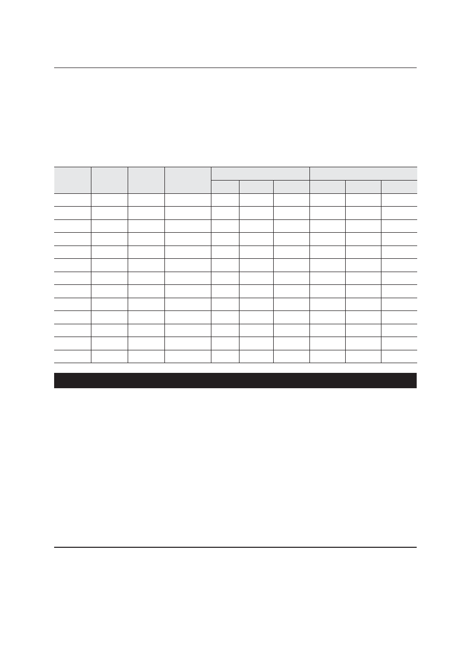
Table of Standard Tightening Torques 

Bolt 

diameter

Bolt 

grade

Wrench 

size

Hex wrench 

size

Hexagonal bolt

Hexagonal socket head bolt

N·m

kgf·m

lbf·ft

N·m

kgf·m

lbf·ft

M6

10.9

10

4

13.2

1.37

9.74

13.2

1.37

9.74

M8

10.9

13

6

31

3.16

22.87

31

3.16

22.87

M10

10.9

17

8

66

6.73

48.7

66

6.73

48.7

M12

10.9

19

10

113

11.53

83.39

113

11.53

83.39

M14

10.9

22

12

177

18.06

130.6

177

18.06

130.6

M16

10.9

24

14

279

28.47

205.9

279

28.47

205.9

M18

10.9

27

14

382

38.98

281.9

382

38.98

281.9

M20

10.9

30

17

549

56.02

405.16

549

56.02

405.16

M27

10.9

41

19

1320

134.7

974.16

1320

134.7

974.16

M10

12.9

17

6

78

7.96

57.76

78

7.96

57.76

M12

12.9

19

8

137

13.98

101.1

137

13.98

101.1

M16

12.9

24

14

339

34.6

250.18

339

34.6

250.18

M20

12.9

30

17

664

67.75

490

664

67.75

490

Table of tightening torques for bolts and nuts

Unless speci

fi

 ed otherwise, tighten metric nuts and bolts to the torque below. (When using

torque wrench)

NOTICE

The following items apply to fi ne thread and coarse thread.

Apply grease (zinc white B dissolved in spindle oil) onto the nuts and bolts to reduce
the friction coeffi cient. Thrust bolts do not require greasing.

Torque tolerance is ±10%.

Always use bolts of correct length. The tip of bolts with excessive length may contact
the bottom of the bolt hole, resulting in under-tightening. Bolts with inadequate length
may result in insuffi cient fastening.

The torque values listed in the table are intended for general application. If different
torque values are specifi ed for a special purpose, the torque values in this table are not
applicable any more.

Make sure the threads are free of dirt or rusts before installation of nuts and bolts.
1-22

Introduction

1.6  

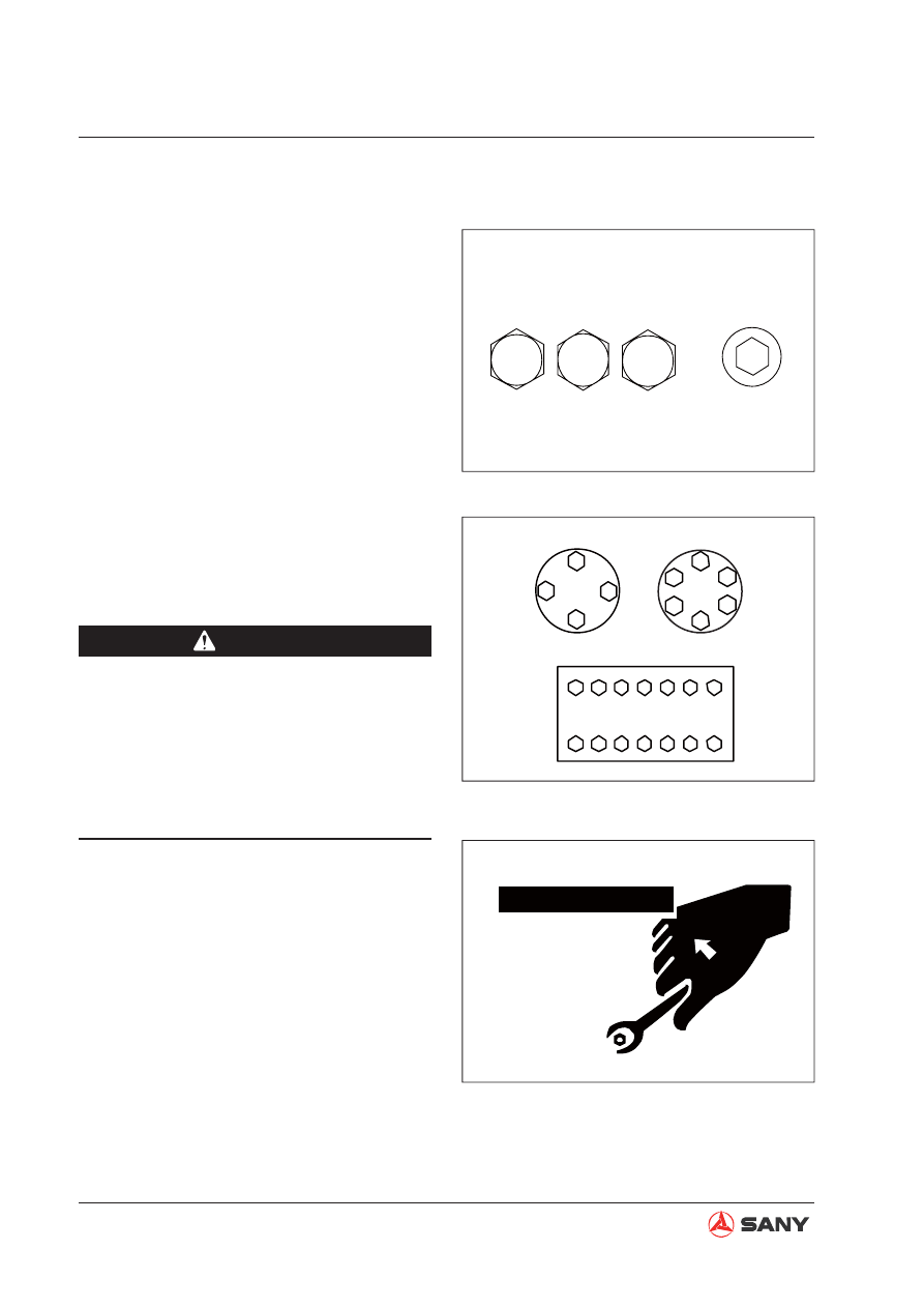
Type of Bolts

Tighten nuts and bolts properly to specified 
torque values. The type and grade of bolts are 
illustrated on the right.

Use correct bolts and tighten them properly 
when assembling machines or components. 

1.7  

Tightening Sequence

When two or more bolts are being tightened, 
follow the tightening sequence shown on the 
right to ensure even tightening.

ZX215-1000031

Hex bolt

Socket head hex bolt

10.9

12.9

8.8

ZX215-1000032

1

2

3

4

5

6

1

2

3

4

5

6

7

8

9

10

11

12

13

14

1

2

3

4

Cross tightening

Diagonal tightening

Central and diagonal tightening

ZX215-1000033


CAUTION

Always use suitable tools for specific
work. Use of improper tools and meth-
ods may cause a hazardous situation.

Use tools of correct sizes when loosen-
ing or tightening the nuts or bolts. Oth-
erwise, the tools may slide and cause
personal injury.

1-23

Introduction

1.8  

Maintenance of Half Flanges

1. Clean the sealing surface of the 

fl

 ange and

check it carefully. Scratches and coarse-
ness cause leaks or abrasion of seals.
Uneven surface may squeeze the seal out.
If these faults are not corrected properly,
parts may have to be replaced.

2. Always use specified O-rings. Check that

the O-rings are not damaged. Do not file
the surface of the O-ring. Apply grease
onto the O-ring to locate it.

3. Tighten the half flanges carefully. Locate

the opening at the center so that it is per-
pendicular to the oil opening. Tighten the
bolt manually to maintain the location of
the components.

1.8.1  Table of tightening torques for half fl ange bolts

Thread diameter of bolt

Width across fl ats

Tightening torque

mm

mm

Nm

kgm

10
12
16

14
17
22

59~74

98~123

235~285

6.0~7.5

10.0~12.5
23.5~29.5

ZX215-1000034

Improper

ZX215-1000035

Unless speci

fi

 ed otherwise, tighten the half 

fl

 ange bolts to the torques below.

1-24

Introduction

1.9  

Conversion Table

The conversion table in this section is provided to enable simple conversion of 

fi

 gures. For details 

of the method of using the conversion table, see the example given below.

Example: 

Method of using the conversion table to convert from millimeters to inches

1. Convert 55 mm into inches

1) Locate the number 50 in the vertical column at the left side, take this as (A), and then draw

a horizontal line from (A).

2) Locate the number 5 in the row across the top, take this as (B), then draw a perpendicular

line down from (B).

3) Take the point where the two lines cross as (C). This point (C) gives the value when con-

verting from millimeters to inches. Therefore, 55 mm = 2.165 inches.

2. Convert 550 mm into inches

1) The number 550 does not appear in the table, so divide it by 10 (move the decimal point

one place to the left) to convert it to 55 mm.

2) Carry out the same procedure as above to convert 55 mm to 2.165 inches.

3) The original value (550 mm) was divided by 10, so multiply 2.165 inches by 10 (move the

decimal point one place to the right) to return to the original value. This gives 550 mm =
21.65 inches.

1-25

Introduction

Millimeters to Inches

1mm=0.03937in

0

1

2

3

4

5

6

7

8

9

0

10
20
30
40

50
60
70
80
90

0.000 
0.394 
0.787 
1.181 
1.575

1.969 
2.362 
2.756 
3.150 
3.543 

0.039 
0.433 
0.827 
1.220 
1.614 

2.008 
2.402 
2.795 
3.189 
3.583 

0.079 
0.472 
0.866 
1.260 
1.654 

2.047 
2.441 
2.835 
3.228 
3.622 

0.118 

0.512 
0.906 
1.299 
1.693 

2.087 
2.480 
2.874 
3.268 
3.661 

0.157 
0.551 
0.945 
1.339 
1.732

2.126 
2.520 
2.913 
3.307 
3.701 

0.197 
0.591 
0.984 
1.378 
1.772


2.165 
2.559 
2.953 
3.346 
3.740 

0.236 
0.630 
1.024 
1.417 

1.811 

2.205 
2.598 
2.992 
3.386 
3.780 

0.276 
0.669 
1.063 
1.457 
1.850 

2.244 
2.638 
3.031 
3.425 
3.819 

0.315 
0.709 
1.102 
1.496 
1.890 

2.283 
2.677 
3.071 
3.465 
3.858 

0.354 
0.748 
1.142 
1.535 
1.929

2.323 
2.717 

3.110 

3.504 
3.898 

(B)

(C)

(A)

Millimeters to Inches

1mm=0.03937in

0

1

2

3

4

5

6

7

8

9

0

10
20
30
40

50
60
70
80
90

0

0.394 
0.787 
1.181 
1.575 

1.969 
2.362 
2.756 
3.150 
3.543 

0.039 
0.433 
0.827 
1.220 
1.614 

2.008 
2.402 
2.795 
3.189 
3.583 

0.079 
0.472 
0.866 
1.260 
1.654 

2.047 
2.441 
2.835 
3.228 
3.622 

0.118 

0.512 
0.906 
1.299 
1.693 

2.087 
2.480 
2.874 
3.268 
3.661 

0.157 
0.551 
0.945 
1.339 
1.732

2.126 
2.520 
2.913 
3.307 
3.701 

0.197 
0.591 
0.984 
1.378 
1.772 

2.165 
2.559 
2.953 
3.346 
3.740 

0.236 
0.630 
1.024 
1.417 

1.811

2.205 
2.598 
2.992 
3.386 
3.780 

0.276 
0.669 
1.063 
1.457 
1.850

2.244 
2.638 
3.031 
3.425 
3.819 

0.315 
0.709 
1.102 
1.496 
1.890

2.283 
2.677 
3.071 
3.465 
3.858 

0.354 
0.748 
1.142 
1.535 
1.929 

2.323 
2.717 

3.110 

3.504 
3.898 

Length

1-26

Introduction

Inches to Millimeters

in.

mm

in.

mm

  1/64

0.3969 

 33/64

13.0969 

  1/32

0.7938 

 17/32

13.4938 

  3/64

1.1906 

 35/64

13.8906 

  1/16

1.5875 

  9/16

14.2875 

  5/64

1.9844 

 37/64

14.6844 

  3/32

2.3813 

 19/32

15.0813 

  7/64

2.7781 

 39/64

15.4781 

  1/8 

3.1750 

  5/8 

15.8750 

  9/64

3.5719 

 41/64

16.2719 

  5/32

3.9688 

 21/32

16.6688 

 11/64

4.3656 

 43/64

17.0656 

  3/16

4.7625 

 11/16

17.4625 

 13/64

5.1594 

 45/64

17.8594 

  7/32

5.5563 

 23/32

18.2563 

 15/64

5.9531 

 47/64

18.6531 

  1/4 

6.3500 

  3/4 

19.0500 

 17/64

6.7469 

 49/64

19.4469 

  9/32

7.1438 

 25/32

19.8438 

 19/64

7.5406 

 51/64

20.2406 

  5/16

7.9375 

  13/16

20.6375 

 21/64

8.3344 

 53/64

21.0344 

 11/32

8.7313 

 27/32

21.4313 

 23/64

9.1281 

 55/64

21.8281 

  3/8 

9.5250 

  7/8 

22.2250 

 25/64

9.9219 

 57/64

22.6219 

 13/32

10.3188 

 29/32

23.0188 

 27/64

10.7156 

 59/64

23.4156 

  7/16

11.1125 

 15/16

23.8125 

 29/64

11.5094 

 61/64

24.2094 

 15/32

11.9063 

 31/32

24.6063 

 31/64

12.3031 

 63/64

25.0031 

  1/2 

12.7000 

1      

25.4000 

1-27

Introduction

Feet to Meters

Meters to Feet

1-28

Introduction

Introduction

Area

Square inches to square centimeters

1-39

Introduction

Temperature

A simple way to convert a Fahrenheit temperature reading into a Centigrade temperature reading 
(or vice versa) is to enter the following table in the center (boldface column) of 

fi

 gures. These 

fi

 g-

ures refer to the temperature in either Fahrenheit or Centigrade degrees.

To convert from Fahrenheit to Centigrade degrees, consider the center column as Fahrenheit 
temperatures and read the corresponding Centigrade temperature in the column at the left.

To convert from Centigrade to Fahrenheit degrees, consider the center column as Centigrade val-
ues, and read the corresponding Fahrenheit temperature on the right.

1-40

Introduction

°C

°C

°F

°F

27.2 

27.8 

28.3 

28.9 

29.4 

81

81

82

82

83

83

84

84

85

85

177.8 

179.6 

181.4 

183.2 

185.0 

30.0 

30.6 

31.1 

31.7 

32.2 

86

86

87

87

88

88

89

89

90

90

186.8 

188.6 

190.4 

192.2 

194.0 

32.8 

33.3 

33.9 

34.4 

35.0 

91

91

92

92

93

93

94

94

95

95

195.8 

197.6 

199.4 

201.2 

203.0 

35.6 

36.1 

36.7 

37.2 

37.8 

96

96

97

97

98

98

99

99

100

100

204.8 

206.6 

208.4 

210.2 

212.0 

40.6 

43.3 

46.1 

48.9 

51.7 

105

105

110

110

115

115

120

120

125

125

221.0 

230.0 

239.0 

248.0 

257.0 

54.4 

57.2 

60.0 

62.8 

65.6 

130

130

135

135

140

140

145

145

150

150

266.0 

275.0 

284.0 

293.0 

302.0 

68.3 

71.1 

73.9 

76.7 

79.4 

155

155

160

160

165

165

170

170

175

175

311.0 

320.0 

329.0 

338.0 

347.0 

°C

°C

°F

°F

7.8 

8.3 

8.9 

9.4 

10.0 

46

46

47

47

48

48

49

49

50

50

114.8 

116.6 

118.4 

120.2 

122.0 

10.6 

11.1 

11.7 

12.2 

12.8 

51

51

52

52

53

53

54

54

55

55

123.8 

125.6 

127.4 

129.2 

131.0 

13.3 

13.9 

14.4 

15.0 

15.6 

56

56

57

57

58

58

59

59

60

60

132.8 

134.6 

136.4 

138.2 

140.0 

16.1 

16.7 

17.2 

17.8 

18.3 

61

61

62

62

63

63

64

64

65

65

141.8 

143.6 

145.4 

147.2 

149.0 

18.9 

19.4 

20.0 

20.6 

21.1 

66

66

67

67

68

68

69

69

70

70

150.8 

152.6 

154.4 

156.2 

158.0 

21.7 

22.2 

22.8 

23.3 

23.9 

71

71

72

72

73

73

74

74

75

75

159.8 

161.6 

163.4 

165.2 

167.0 

24.4 

25.0 

25.6 

26.1 

26.7 

76

76

77

77

78

78

79

79

80

80

168.8 

170.6 

172.4 

174.2 

176.0 

°C

°C

°F

°F

-11.7 

-11.1 

-10.6 

-10.0 

-9.4 

11

11

12

12

13

13

14

14

15

15

51.8 

53.6 

55.4 

57.2 

59.0 

-8.9 

-8.3 

-7.8 

-7.2 

-6.7 

16

16

17

17

18

18

19

19

20

20

60.8 

62.6 

64.4 

66.2 

68.0 

-6.1 

-5.6 

-5.0 

-4.4 

-3.9 

21

21

22

22

23

23

24

24

25

25

69.8 

71.6 

73.4 

75.2 

77.0 

-3.3 

-2.8 

-2.2 

-1.7 

-1.1 

26

26

27

27

28

28

29

29

30

30

78.8 

80.6 

82.4 

84.2 

86.0 

-0.6 

0.0 

0.6 

1.1 

1.7 

31

31

32

32

33

33

34

34

35

35

87.8 

89.6 

91.4 

93.2 

95.0 

2.2 

2.8 

3.3 

3.9 

4.4 

36

36

37

37

38

38

39

39

40

40

96.8 

98.6 

100.4 

102.2 

104.0 

5.0 

5.6 

6.1 

6.7 

7.2 

41

41

42

42

43

43

44

44

45

45

105.8 

107.6 

109.4 

111.2 

113.0 

°C

°C

°F

°F

-40.0 

-37.2 

-34.4 

-31.7 

-28.9 

-40

-40

-35

-35

-30

-30

-25

-25

-2

-20

-40.0 

-31.0 

-22.0 

-13.0 

-4.0 

-28.3 

-27.8 

-27.2 

-26.7 

-26.1 

-19

-19

-18

-18

-17

-17

-16

-16

-15

-15

-2.2 

-0.4 

1.4 

3.2 

5.0 

-25.6 

-25.0 

-24.4 

-23.9 

-23.3 

-14

-14

-13

-13

-12

-12

-11

-11

-10

-10

6.8 

8.6 

10.4 

12.2 

14.0 

-22.8 

-22.2 

-21.7 

-21.1 

-20.6 

-9

-9

-8

-8

-7

-7

-6

-6

-5

-5

15.8 

17.6 

19.4 

21.2 

23.0 

-20.0 

-19.4 

-18.9 

-18.3 

-17.8 

-4

-4

-3

-3

-2

-2

-1

-1

0

24.8 

26.6 

28.4 

30.2 

32.0 

-17.2 

-16.7 

-16.1 

-15.6 

-15.0 

1

2

3

4

5

33.8 

35.6 

37.4 

39.2 

41.0 

-14.4 

-13.9 

-13.3 

-12.8 

-12.2 

6

7

8

9

10

10

42.8 

44.6 

46.4 

48.2 

50.0 

1°C = 33.8°F

Shop Safety

Shop Safety

2-1

2 Shop Safety

2.1 Hazard Alert Information .......................................................................................... 2-3
2.2  General Shop Safety ............................................................................................... 2-6

2.2.1  Rules and shop behavior ............................................................................... 2-7
2.2.2 Housekeeping ................................................................................................ 2-7
2.2.3  Shop Liquids Storage..................................................................................... 2-8
2.2.4 Cleaning Parts ............................................................................................... 2-8
2.2.5  Jacking Up the Machine................................................................................. 2-9
2.2.6 Electrical Dangers .......................................................................................... 2-9
2.2.7 Removing Attachments ................................................................................ 2-10
2.2.8  Cleaning the Machine .................................................................................. 2-10
2.2.9  Using the Correct Tools ................................................................................ 2-10
2.2.10  Hoisting a Load ...........................................................................................2-11
2.2.11 Appropriate Working Apparel ..................................................................... 2-12
2.2.12 Safety Partners .......................................................................................... 2-12
2.2.13  Two people when engine running .............................................................. 2-13
2.2.14 Driving Pins ................................................................................................ 2-13
2.2.15  Aligning Parts or Components ................................................................... 2-14
2.2.16  Fire Extinguisher and Emergency Exits ..................................................... 2-14
2.2.17  Personal Protective Equipment.................................................................. 2-14
2.2.18  Running the Machine ................................................................................. 2-15
2.2.19 Accumulator ............................................................................................... 2-16
2.2.20  Adding Fluids to a System ......................................................................... 2-16
2.2.21  Track Recoil Springs .................................................................................. 2-17
2.2.22  High-Pressure Fluid Lines.......................................................................... 2-17
2.2.23  Safe Work Preparations ............................................................................. 2-18
2.2.24  Mounting and Dismounting ........................................................................ 2-19

Shop Safety

2-2


WARNING

Read and understand all safety precau-
tions and instructions in this manual be-
fore reading any other manuals provided 
with this machine and before operating or 
servicing the machine. Also read the safety 
information on machine decals before per-
forming any operations. Failure to do so 
can cause machine damage, personal in-
jury or death.

2.2.25 Battery Hazards ......................................................................................... 2-20
2.2.26 Jump-Start Safety ...................................................................................... 2-21
2.2.27  Disconnecting the System Power .............................................................. 2-21
2.2.28 Lockout/tagout ........................................................................................... 2-22
2.2.29  Sequence of Procedures ........................................................................... 2-22
2.2.30 Chemical hazard ........................................................................................ 2-24
2.2.31  Material Safety Data Sheets (MSDS) ........................................................ 2-24

2.3  Precautions for sling work and giving signals ........................................................ 2-25

2-3

Shop Safety

2 SHOP SAFETY

2.1  

Hazard Alert Information

Most accidents are usually caused by the fail-
ure to follow fundamental repair procedures 
and safety rules for the system under repair. 
To avoid accidents it is important to read and 
understand all information outlined in this 
manual before performing repairs on the ma-
chine system.

The following (ANSI/ISO) signal words are 
used to inform you that there is a potentially 
hazardous situation that may lead to damage, 
personal injury or even death. In this manual, 
on the machine, part or component decals and 
different signal words are used to express the 
potential level of a hazard.


DANGER

Indicates an imminent hazard which WILL 
result in serious injury or death if message 
is ignored.


WARNING

Indicates a potentially hazardous situation 
which COULD result in serious injury or 
death if message is ignored.


CAUTION

Indicates a potentially hazardous situation 
which COULD RESULT IN MINOR OR MA-
JOR INJURY 
if message is ignored.

NOTICE

Indicates THE MACHINE MAY BE DAM-
AGED if improperly operated or main-
tained.

2-4

Shop Safety

SANY cannot predict every circumstance that 
might involve a potential hazard in a repair of 
the machine. Therefore the safety message in 
this manual and on the machine may not in-
clude all possible safety precautions.

If any procedures or actions not speci

fi

 ed, rec-

ommended or allowed in this manual are used, 
you must be sure that you and others can 
perform such procedures and actions safely 
and without damaging the machine. If you are 
unsure about the safety of some procedures, 
contact your SANY representative.

This is to alert the user of a hazard. It is 
usually used in a graphic.

This symbol is used in a graphic to alert 
the user to not do something.

2-5

Shop Safety


WARNING

Improper repair procedures on this ma-
chine can be hazardous and could re-
sult in serious injury or even death.

All personnel involved with the repair
of this machine must read this manual
thoroughly before performing any pro-
cedures on this equipment.

Some actions involved in the operation
or repair of this machine could cause
a serious accident if they are not per-
formed in the manner described in this
manual.

All precautions outlined in this manual
apply only to intended repair proce-
dures of the machine or system. If you
perform any repairs not specifi cally pro-
hibited, you must be sure that it is safe
for you and others. In no event should
you or others engage in prohibited uses
or actions as described in this manual.

SANY delivers machines that comply
with all applicable regulations and
standards of the country to which the
machines have been shipped. If this
machine has been purchased in another
country or purchased from someone
in another country, it may lack certain
safety features and specifications that
are necessary for use in your country.
If there is any question about whether
your product complies with the appli-
cable standards and regulations of your
country, contact your SANY representa-
tive before performing repairs on this
machine.


Content      ..     1      2      3      4      ..