SANY Crawler Hydraulic Excavator SY195C9, SY205C9, SY215C9, SY225C9. Service Manual - page 2
 

  Index      Manuals     SANY Crawler Hydraulic Excavator SY195C9, SY205C9, SY215C9, SY225C9. Service Manual (2013)


Search            copyright infringement  


Content      ..      1      2      3      ..


SANY Crawler Hydraulic Excavator SY195C9, SY205C9, SY215C9, SY225C9. Service Manual - page 2


1-5

Introduction

1.2  Terms for Maintenance Standard

1. Standard size and tolerance

To be accurate, the finishing size of parts
is a little different from one to another.

To specify a 

fi

 nishing size of a part, a tem-

porary standard size is set and an allow-
able difference from that size is indicated.

The above size set temporarily is called
the "standard size" and the range of differ-
ence from the standard size is called the
"tolerance".

The tolerance with the symbols of + or – is
indicated on the right side of the standard
size.

NOTE: The tolerance may be indicated in 
the text and a table as [standard size (upper 
limit of tolerance/lower limit of tolerance)]. 
Example) 120 (–0.022/–0.126)

Usually, the size of a hole and the size
of the shaft to be 

fi

 tted to that hole are

indicated by the same standard size
and different tolerances of the hole and
shaft. The tightness of 

fi

 t is decided by

the tolerance.

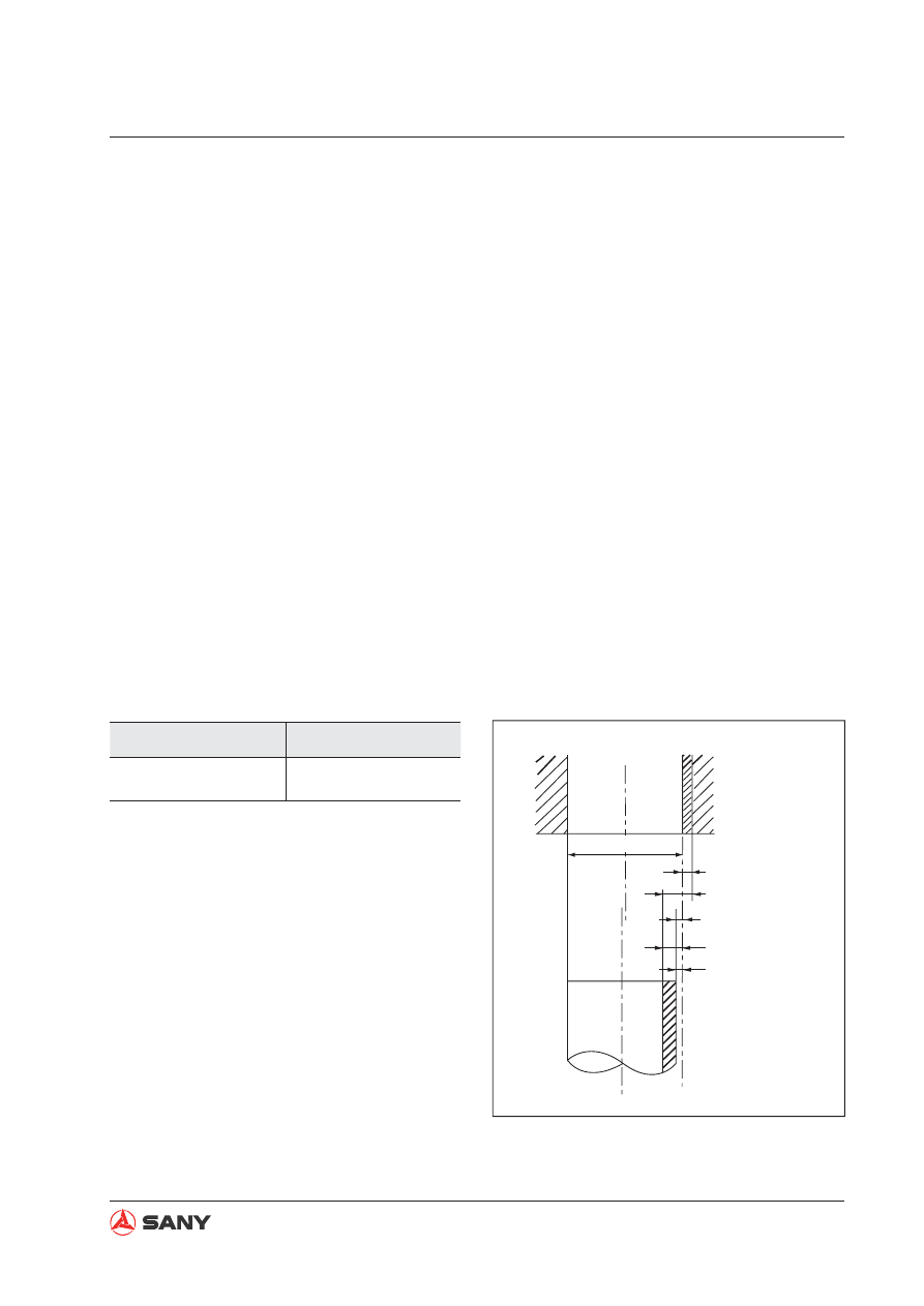
Indication of size of rotating shaft and
hole and relationship drawing of them.

Example

Standard size

Tolerance

120

–0.022
–0.126

ZX215-1000003

Tolerance of hole
(upper):+0.046

Std.clearance (max.):0.122

Std.clearance (min.):0.030

Tolerance of shaft
(lower):-0.076
Tolerance of shaft
(upper):-0.030

Std.size 

F

 60

The maintenance standard values necessary 
for judgment of products and parts are de-
scribed by the following terms.
1-6

Introduction

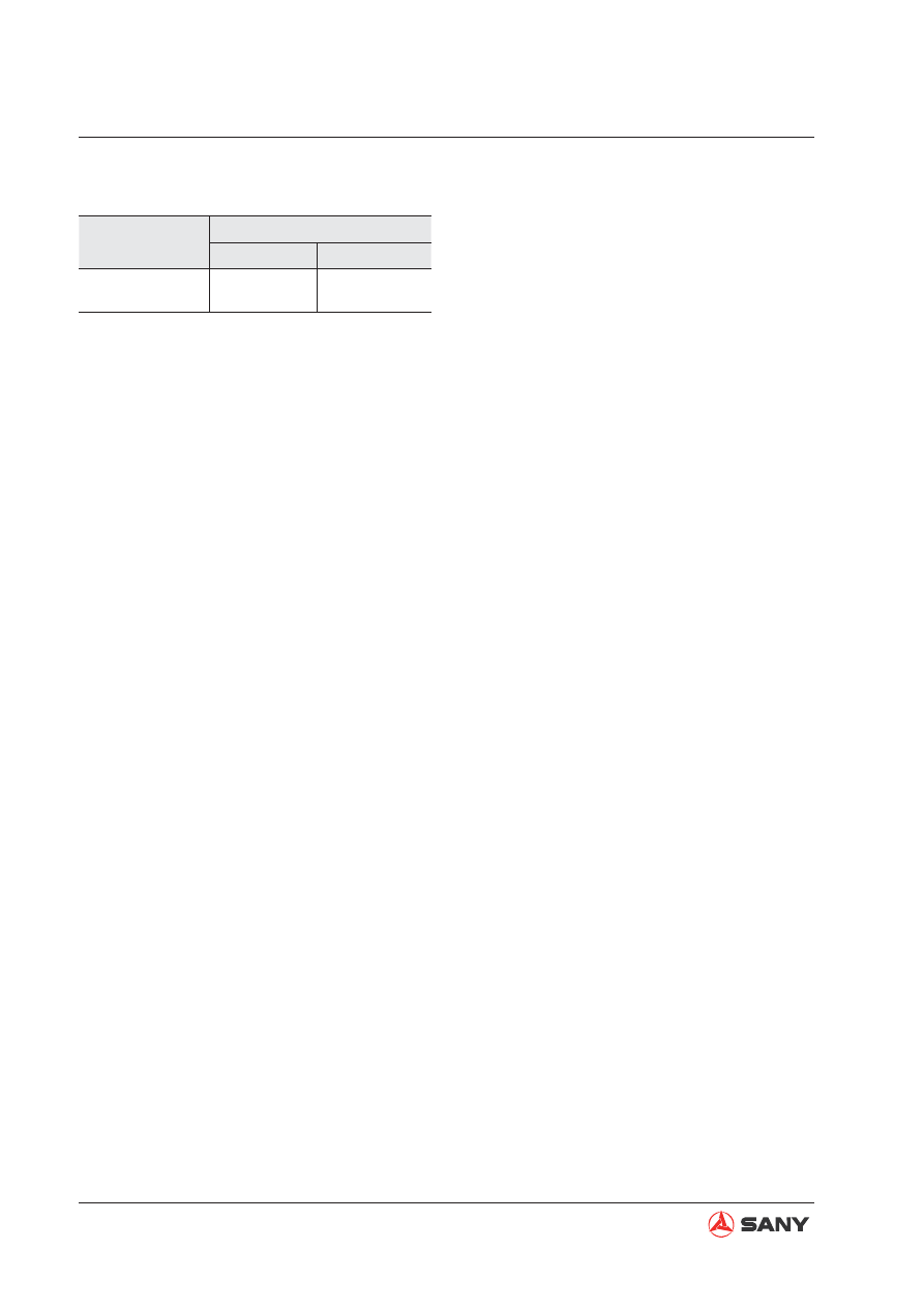
Example

Standard size

Tolerance

Shaft

Hole

φ

60

-0.030
-0.076

+0.046

0

2. Standard clearance and standard value

The clearance made when new parts are
assembled is called the "standard clear-
ance", which is indicated by the range from
the minimum clearance to the maximum
clearance.

When some parts are repaired, the clear-
ance is generally adjusted to the standard
clearance.

A value of performance and function of
new products or equivalent is called the
"standard value", which is indicated by a
range or a target value.

When some parts are repaired, the value
of performance/function is set to the stan-
dard value.

3. Standard interference

When the size of a hole is smaller than the
size of a shaft because of the standard
size and tolerance, the difference between
these sizes is called the "interference".

The range (A – B) from the difference (A)
between the minimum size of the shaft and
the maximum size of the shaft to the differ-
ence (B) between the maximum size of the
shaft and the minimum size of the hole is
the "standard interference".

After repairing or replacing some parts,
measure the size of their hole and shaft
and check that the interference is in the
standard range.

4. Repair limit and allowable value

The size of a part changes due to wear
and deformation while it is used. The limit
of changed size is called the "repair limit".

If a part is worn to the repair limit must be
replaced or repaired.

The performance and function of a product
lowers while it is used. A value below which
the product can be used without causing a
problem is called the "allowable value".

If a product is worn to the allowable value,
it must be checked or repaired. Since the
permissible value is estimated from vari-
ous tests or experiences in most cases,
however, it must be judged after consider-
ing the operating condition and customer's
requirement.

5. Clearance limit

Parts can be used until the clearance be-
tween them is increased to a certain limit.
The limit at which those parts cannot be
used is called the "clearance limit".

If the clearance between the parts exceeds
the clearance limit, they must be replaced
or repaired.

6. Interference limit

The allowable maximum interference be-
tween the hole of a part and the shaft of
another part to be assembled is called the
"interference limit".

The interference limit shows the repair limit
of the part of smaller tolerance.

If the interference between the parts ex-
ceeds the interference limit, they must be
replaced or repaired.

1-7

Introduction

1.3  

Handling Electrical and Hydraulic Components

To maintain the performance of the machine 
over a long period, and to prevent failures or 
other troubles before they occur, correct "oper-
ation", "maintenance and inspection", "trouble-
shooting", and "repairs" must be carried out. 
This section deals particularly with correct re-
pair procedures for mechatronics and is aimed 
at improving the quality of repairs. For this 
purpose, it gives sections on "Handling electric 
components" and "Handling hydraulic equip-
ment" (particularly gear oil and hydraulic oil).

1.3.1  Points to remember when handling electric components

1. Handling wiring harnesses and connec-

tors

Wiring harnesses consist of wiring con-
necting one component to another compo-
nent, connectors used for connecting and
disconnecting one wire from another wire,
and protectors or tubes used for protecting
the wiring.

Compared with other electrical compo-
nents fitted in boxes or cases, wiring
harnesses are more likely to be affected
by the direct effects of rain, water, heat, or
vibration. Furthermore, during inspection
and repair operations, they are frequently
removed and installed again, so they are
likely to suffer deformation or damage. For
this reason, it is necessary to be extremely
careful when handling wiring harnesses.

1-8

Introduction

Improper insertion

ZX215-1000005

ZX215-1000006

Crimped portion

ZX215-1000007

3) Disconnections in wiring

If the wiring is held and the connectors are
pulled apart, or components are lifted with
a crane with the wiring still connected, or a
heavy object hits the wiring, the crimping of
the connector may separate, or the solder-
ing may be damaged, or the wiring may be
broken.

2. Main failures occurring in wiring har-

ness

1) Defective contact of connectors (defective

contact between male and female)

Problems with defective contact are likely
to occur because the male connector is not
properly inserted into the female connector,
or because one or both of the connectors
is deformed or the position is not correctly
aligned, or because there is corrosion or
oxidation of the contact surfaces.

2) Defective crimping or soldering of connec-

tors

The pins of the male and female connec-
tors are in contact at the crimped terminal
or soldered portion, but if there is exces-
sive force brought to bear on the wiring,
the plating at the joint will peel and cause
improper connection or breakage.

1-9

Introduction

4) High-pressure water entering connector

The connector is designed to make it 
difficult for water to enter (drip-proof 
structure), but if high-pressure water is 
sprayed directly on the connector, water 
may enter the connector, depending on the 
direction of the water jet. Accordingly, take 
care not splash water over the connector. 
The connector is designed to prevent 
water from entering, but at the same time, 
if water does enter, it is difficult for it to 
be drained. Therefore, if water should get 
into the connector, the pins will be short-
circuited by the water, so if any water gets 
in, immediately dry the connector or take 
other appropriate action before passing 
electricity through it.

ZX215-1000008

5) Oil or dirt stuck to connector

If oil or grease are stuck to the connector 
and an oil film is formed on the mating 
surface between the male and female pins, 
the oil will not let the electricity pass, so 
there will be defective contact. If there is 
oil or grease stuck to the connector, wipe 
it off with a dry cloth or blow it dry with 
compressed air and spray it with a contact 
restorer.

NOTE:

When wiping the mating portion of the
connector, be careful not to use exces-
sive force or deform the pins.

If there is oil or water in the com-
pressed air, the contacts will become
even dirtier, so remove the oil and wa-
ter from the compressed air completely
before cleaning with compressed air.

ZX215-1000009

1-10

Introduction

3. Removing, installing, and drying con-

nectors and wiring harnesses

1) Disconnecting connectors

a. Hold the connectors when disconnect-

ing.

When disconnecting the connectors,
hold the connectors. For connectors
held by a screw, loosen the screw fully,
then hold the male and female connec-
tors in each hand and pull apart. For
connectors which have a lock stop-
per, press down the stopper with your
thumb and pull the connectors apart.

NOTE: Never pull with one hand.

b. When removing from clips

Both of the connector and clip have
stoppers, which are engaged with each
other when the connector is installed.

ZX215-1000010

Press lightly 

when removing

Lock stopper

ZX215-1000011

Both stoppers

When removing a connector from a clip,
pull the connector in a parallel direction
to the clip for removing stoppers.

ZX215-1000012

Introduction

c. Action to take after removing connec-

tors

After removing any connector, cover
it with a vinyl bag to prevent any dust,
dirt, oil, or water from getting in the
connector portion.

NOTE: If the machine is left disas-
sembled for a long time, it is particularly
easy for improper contact to occur, so
always cover the connector.

ZX215-1000013

ZX215-1000022

Clicks into position

2) Connecting connectors

a. Check the connector visually

Check that there is no oil, dirt, or water
stuck to the connector pins (mating por-
tion).

Check that there is no deformation, de-
fective contact, corrosion, or damage to
the connector pins.

Check that there is no damage or
breakage to the outside of the connec-
tor.

NOTE: If there is any oil, water, or dirt
stuck to the connector, wipe it off with
a dry cloth. If any water has got inside
the connector, warm the inside of the
wiring with a dryer, but be careful not to
make it too hot as this will cause short
circuits.

NOTE: If there is any damage or break-
age, replace the connector.

1-12

Introduction

3) Connecting DT connectors

Since the DT 8-pin and 12-pin heavy duty
wire connectors have 2 latches respec-
tively, push them in until they click 2 times.

Male connector: 1

Female connector: 2

Normal locking state (Horizontal): a, b,
d

Incomplete locking state (Diagonal): c

ZX215-1000015

ZX215-1000016

2

a

1

c

b

d

b. Fix the connector securely.

Align the position of the connector cor-
rectly, and then insert it securely. For
connectors with lock stopper, push in
the connector until the stopper clicks
into position.

c. Correct any protrusion of the boot and

any misalignment of the wiring harness.

For connectors 

fi

 tted with boots, correct

any protrusion of the boot. In addition, if
the wiring harness is misaligned, or the
clamp is out of position, adjust it to its
correct position.

NOTE: If the connector cannot be cor-
rected easily, remove the clamp and
adjust the position.

If the connector clamp has been re-
moved, be sure to return it to its origi-
nal position. Check also that there are
no loose clamps.

ZX215-1000014

1-13

Introduction

4) Drying wiring harness

If there is any oil or dirt on the wiring
harness, wipe it off with a dry cloth. Avoid
washing it in water or using steam. If the
connector must be washed in water, do not
use high-pressure water or steam directly
on the wiring harness. If water gets directly
on the connector, do as follows.

a. Disconnect the connector and wipe off

the water with a dry cloth.

NOTE: If the connector is blown dry
with compressed air, there is the risk
that oil in the air may cause defective
contact, so remove all oil and water
from the compressed air before blowing
with air.

b. Dry the connector with a dryer.

If water gets inside the connector, use
a dryer to dry the connector.

NOTE: Hot air from the dryer can be
used, but regulate the time that the
hot air is used in order not to make the
connector or related parts too hot, as
this will cause deformation or damage
to the connector.

c. Carry out a continuity test on the con-

nector.

After drying, leave the wiring harness
disconnected and carry out a continuity
test to check for any short circuits be-
tween pins caused by water.

NOTE: After completely drying the con-
nector, blow it with contact restorer and
reassemble.

ZX215-1000018

T adapter

ZX215-1000017

ZX215-1000009

1-14

Introduction

ZX215-1000021

4. Handling the integrated control monitor

1) The controller contains a microcomputer

and an electronic control circuits. They
control all of the electronic circuits on the
machine, so be extremely careful when
handling the integrated control monitor.

2) Do not place objects on the controller.

3) Cover the control connectors with tape or a

vinyl bag. Never touch the connector con-
tacts with your hand.

4) Do not leave it where it may be exposed to

rain.

5) Do not place the controller on oil, water, or

soil, or in any hot place, even for a short
time.

6) Precautions for arc welding

When welding on the controller, disconnect
all wiring harness connectors connected
to the controller. Fit an arc welding ground
close to the welding point.

ZX215-1000019

ZX215-1000020

Tool Box

1-15

Introduction

5. Points to remember when troubleshoot-

ing electric circuits

1) Always turn the power OFF before discon-

necting or connecting connectors.

2) Before carrying out troubleshooting, check

that all the related connectors are properly
inserted.

NOTE: Disconnect and connect the related
connectors several times to check.

3) Always connect any disconnected connec-

tors before going on to the next step.

NOTE: If the power is turned ON with the
connectors still disconnected, unnecessary
abnormality displays will be generated.

4) When carrying out troubleshooting of cir-

cuits (measuring the voltage, resistance,
continuity, or current), move the related
wiring and connectors several times and
check that there is no change in the read-
ing of the tester.

NOTE: If there is any change, there is
probably defective contact in that circuit.

1-16

Introduction

1.3.2  Points to remember when handling hydraulic equipment

1. Be careful of the operating environment

Avoid adding hydraulic oil, replacing 

fi

 lters,

or repairing the machine in rain or high
winds, or places where there is a lot of
dust.

2. Disassembly and maintenance work in

the fi eld

If disassembly or maintenance work is
carried out on hydraulic equipment in the
field, there is danger of dust entering the
equipment. It is also difficult to check the
performance after repairs, so it is desir-
able to use unit exchange. Disassembly
and maintenance of hydraulic equipment
should be carried out in a specially pre-
pared dust-proof workshop, and the perfor-
mance should be checked with special test
equipment.

3. Sealing openings

After any piping or equipment is removed,
the openings should be sealed with caps,
tapes, or vinyl bags to prevent any dirt or
dust from entering. If the opening is left
open or is blocked with a rag, there is
danger of dirt entering or of the surround-
ing area being made dirty by leaking oil so
never do this. Do not simply drain oil out
onto the ground, but collect it and ask the
customer to dispose of it, or take it back
with you for disposal.

ZX215-1000023

ZX215-1000024

With the increase in pressure and precision 
of hydraulic equipment, the most common 
cause of failure is dirt (foreign material) in the 
hydraulic circuit. When adding hydraulic oil, or 
when disassembling or assembling hydraulic 
equipment, it is necessary to be particularly 
careful.

1-17

Introduction

4. Do not let any dirt or dust get in during

refi lling operations

Be careful not to let any dirt or dust get
in when refilling with hydraulic oil. Always
keep the oil filler and the area around it
clean, and also use clean pumps and oil
containers. If an oil cleaning device is
used, it is possible to 

fi

 lter out the dirt that

has collected during storage, so this is an
even more effective method.

ZX215-1000025

5. Change hydraulic oil when the tempera-

ture is high

When hydraulic oil or other oil is warm, it
flows easily. In addition, the sludge can
also be drained out easily from the circuit
together with the oil, so it is best to change
the oil when it is still warm. When changing
the oil, as much as possible of the old
hydraulic oil must be drained out. (Drain
the oil from the hydraulic tank; also drain
the oil from the filter and from the drain
plug in the circuit.) If any old oil is left, the
contaminants and sludge in it will mix with
the new oil and will shorten the life of the
hydraulic oil.

6. Flushing operations

After disassembling and assembling the
equipment, or changing the oil, use 

fl

 ush-

ing oil to remove the contaminants, sludge,
and old oil from the hydraulic circuit.
Normally, flushing is carried out twice:
primary 

fl

 ushing is carried out with 

fl

 ushing

oil, and secondary flushing is carried out
with the speci

fi

 ed hydraulic oil.

ZX215-1000026

Flushing oil

1-18

Introduction

7. Cleaning operations

After repairing the hydraulic equipment
(pump, control valve, etc.) or when run-
ning the machine, carry out oil cleaning
to remove the sludge or contaminants in
the hydraulic oil circuit. The oil cleaning
equipment is used to remove the ultra 

fi

 ne

(about 3 

μ

) particles that the filter built in

the hydraulic equipment cannot remove, so
it is an extremely effective device.

1.4  

Hose Connector

Hose connector is used to connect hoses with 
a small diameter. The metal sealing surface (4) 
of the joint (1) must be in close contact with 
the metal sealing surface (5) of the hose (2) to 
seal pressurized oil.

ZX215-1000028

1

2

3

4

5

Connector

NOTICE

Do not over-tighten the nut (3). Exces-
sive force applied on the metal sealing
surface (4) and (5) may cause the joint
(1) to break. Be sure to tighten nut (3)
according to technical specifi cations.

Scratches or other damages on seal-
ing surface (4) and (5) may cause leaks
at the joint. Be extremely careful not
to damage the sealing surfaces during
connecting and disconnecting work.

1-19

Introduction

1.4.1  Type of hose connector

ZX215-1000029

24

°

24

°

Female

Male

Type

Wrench size mm

Wrench size mm

Tightening torque

Connecting nut

Hose joint

N·m(kgf·m,Ibf·ft)

24° Male

19

19

59(6,44)

22

22

98(10,72)

27

27

118(12,87)

36

36

235(24,173)

41

41

295(30,218)

50

50

490(50,361)

60

60

670(68,494)

70

70

980(100,723)

24° Female

19

17

44(4.5,32)

22

19

59(6,44)

27

22

118(12,87)

36

30, 32

235(24,173)

41

36

295(30,218)

50

46

490(50,361)

1.4.2  Hose connector tightening torque table

NOTICE

The torque values listed in the table are
intended for general application.

Do not use torque values listed in this
table when different torque values are
specifi ed for a special purpose.

Introduction

Place O-ring (6) in contact with the contact 
surface of the joint (7) to seal the pressurized 
oil.

1.4.3  Connection of O-rings

Wrench size mm

Wrench size mm

Tightening torque

Connecting nut

Hose joint

N·m (kgf·m,Ibf·ft)

19

17

44(4.5,32)

22

19

59(6,44)

27

22

118(12,87)

36

30, 32

235(24,173)

41

36

295(30,218)

50

46

490(50,361)

ZX215-1000030

Hose connector

6

7

8

9

10

NOTICE

Replace o-rings (6) with new ones when
re-connecting hoses.

Before tightening nut (9), make sure the
o-ring (6) has been placed into the o-ring
seat (8).Displacement of the o-ring may
have it damaged and cause leaks.

Be careful not to damage the o-ring seat
(8) or the sealing surface (10). Damaged
o-ring (6) may cause oil leakage.

If oil leakage due to loosened nut (9) is
detected, do not try to stop the leakage
by tightening nut (9). Instead, replace o-
ring (6) with a new one and make sure it
is well positioned, and tighten nut (9).


Content      ..      1      2      3      ..