SANY Crawler Hydraulic Excavator SY365H-9, SY365BH-9. Shop Manual (2014) - page 35
 

  Index      Manuals     SANY Crawler Hydraulic Excavator SY365H-9, SY365BH-9. Shop Manual (2014)


Search            copyright infringement  


Content      ..     33      34      35      36     ..


SANY Crawler Hydraulic Excavator SY365H-9, SY365BH-9. Shop Manual (2014) - page 35


8-93

Disassembly and Assembly

SY365(B)H-9 Crawler Hydraulic Excavator

ZX335-1006176

13

14

13

12

Tool

Tool

Piston

O-ring

Tool for 
correction

Block

Press in

Press in

2

1

ZX335-1006177

Assembling tool

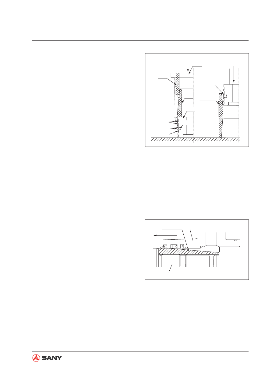
3. Assembling the piston assembly

A.  Installation of seal (14).

Install first the O-ring seal and the
one-side guard ring (13) on the pis-
ton. Place the piston on the press. As
shown in the illustration on the right,
the seal (14) is installed with the tools
indicated.

B.  Correction of seal (14)

Install the seal (14) and the guard ring
(13) on the other side. In order to pre-
vent the expansion of the seal (14), a
corrector must be used to correct the
seal (14) which has been stretched
during installation. The piston rod
may not be able to go in the cylinder
barrel if the seal (14) is not corrected
timely.

C.  Installation of slide ring (12)

Slightly open the slide ring (12) and
install it axially. Excessive opening of
the slide ring (12) can fail installation.

4. Assembling the piston rod assembly

A.  Fix the piston rod (1).

B.  Install the cylinder (2) on the piston rod.

Make sure that the dust ring lip or
the U-ring lip is not stopped by the
shoulder of any part. Install the cyl-
inder head and the piston rod with
the tools.

Fig. 8-187 

Fig. 8-188 

8-94

Disassembly and Assembly

SY365(B)H-9 Crawler Hydraulic Excavator

ZX335-1006179

6

5

23

The opening faces the piston side. 

Rod end buffer

C.  If the bottom side of cylinder contains 

a buffer (not for bucket cylinder), install 
the buffer bearing and the buffer seal in 
the following order. 

a.  Let the notched side of the buffer 

seal (10) face the piston while 
installing the buffer seal (10) in the 
groove. 

b.  Install the buffer sleeve (8) accord-

ing to the indication in the illustration 
on the right. 

c.  Install the stopper ring (11) in the 

groove. Install the elastic ring after 
the buffer sleeve (8) is pushed 
to the bottom. A rubber hammer 
should be used for the tapping job 
in order to avoid damaging the 
piston rod and the buffer bearing. 

D.  If the head side of cylinder contains a 

buffer, install the buffer sleeve (6) and 
the buffer seal (23) according to the 
following order. 

a.  The piston nut must be installed 

after installation of the buffer bear-
ing. 

b.  The buffer seal (23) must be 

installed in the groove, with its 
notches facing the piston. 

c.  The buffer sleeve (6) must be 

installed according to the illustration 
on the right. 

E.  Tighten the piston nut (5). 

 Piston nut (arm):

9600 Nm {979.6 kgm}

 Piston nut (boom and bucket):

6200 Nm {632.6 kgm}


Insufficient tightening can cause oil 
leakage, loose nut and thread break-
age. In addition, excessive tightening 
can cause expansion of the buffer shaft 
on the extending side or deformation of 

ZX335-1006178

9

10

8

11

Head end buffering

With one opening

(Two piece type)

Piston rod

Threads

The opening faces the threads.

Fig. 8-189 

Fig. 8-190 

8-95

Disassembly and Assembly

SY365(B)H-9 Crawler Hydraulic Excavator

3

4

ZX335-1006180

Rivet

Punch

piston on the contact side. 

Thoroughly clean and grease (with ba-
nana oil) the threaded portions of the
piston, nuts and piston rod before tight-
ening the nuts.

F.  Treatment of the piston against loosen-

ing

After the piston nut (5) is tightened, put
in the steel ball (4), tighten the setscrew
(3) and punch to rivet the two periph-
eral points.

 Setscrew (3): 

66.9 Nm {6.8 kgm}

5. Install the piston into the cylinder barrel.

A.  Fix the barrel in a vertical or level man-

ner. 

B.  Install the piston rod into the cylinder 

barrel. 

If 

fi

 xed in a vertical manner, the pis-

ton rod falls into the barrel under its
gravity.

Make sure that the slide ring does
not fall while the piston is inserted
into the barrel.

ZX335-1006181

Tool
Nylon sleeve 
(two pieces)

(Move the notch 
180 degrees away.)

Fig. 8-191 

Fig. 8-192 

8-96

Disassembly and Assembly

SY365(B)H-9 Crawler Hydraulic Excavator

Bolt tightening sequence

8

4

12

6

10

2

1

9

5

11

3

7

ZX335-1006182

6.  Tightening of cylinder head 

Tighten the bolts following the sequence 
shown in the illustration on the right. 

 Bolt: 267 Nm {27.2 kgm}

7.  Install the tubing. 

Fig. 8-193 

8-97

Disassembly and Assembly

SY365(B)H-9 Crawler Hydraulic Excavator

2

3

5

4

1

ZXT335-1006183

7

7

6

7

8

6

ZXT335-1006184

8.28  Work Equipment AS 

8.28.1 Removal

Fully extend the arm and the bucket. Lower 
the work equipment to the ground. Move the 
hydraulic lockout control to the LOCK position. 

Release remaining pressure in the hydraulic  
circuit. See

 “Remaining Pressure in Hydrau-

lic Lines - Relieve” on page 6-36

1.  Disconnect the grease hose (1). 

2.  Lift the boom cylinder assembly (2). 

Remove the lockbolt (3). 

3.  Remove the plate (4) and then the pin roll (5

).                                                         


There are shims installed. Count the 
shims and check the thickness. Place 
the shims in a safe place. 

4.  Start the engine and retract the piston rod.


Secure the piston rod with a wire rope 
in order to prevent the piston from slip-
ping out. Place the cylinder on a bench 
or support. The grease fitting on the 
bottom side must be removed in the 
later case. 


Remove the other boom cylinder in the 
same way. 

5.  Remove the two hoses (6) of bucket 

cylinder and the two hoses (7) of the arm 
cylinder. 


Cork the hoses to prevent out

fl

 ow of oil. 

Tie the hoses to the valve side 

6.  Remove the mid-connector (8) used for 

work lamp. 

Fig. 8-194 

Fig. 8-195 

8-98

Disassembly and Assembly

SY365(B)H-9 Crawler Hydraulic Excavator

9

10

ZXT335-1006185

11

ZXT335-1006186

7. Lift the work equipment and remove the

plate (9). Remove the bottom pin roll (10).

There are shims installed. Count the shims 
and mark their locations. 

8. Lift the work equipment assembly (11) in

order to disassemble it.

  Work equipment assembly: 

Model

Weight

SY365H-9

5,652 kg

SY365BH-9

7,102 kg

Fig. 8-196 

Fig. 8-197 

8-99

Disassembly and Assembly

SY365(B)H-9 Crawler Hydraulic Excavator

a

4

12

ZX335-1006188

8.28.2 Installation


Installation is performed in the reverse pro-
cedure of removal. 


A clearance (a: 0.5 - 1.5 mm) should be 
left between the plate and the nut when 
tightening the locknut. 

 Greasing after assembling the pin: 

Grease (MoS

2

 G2-L1)

a

ZX335-1006187


Adjust the shim thickness in order to 
have a desired clearance (a: 0.5

a

1 mm) between the piston end (12) 

and the plate (4). 


Standard shim thickness: 1.0 mm and 
2.0 mm. 


 Greasing after assembling the pin: 

Grease (MoS

2

 G2-LI)

  WARNING


Never use your finger to align the pin 
holes.  

  WARNING


Never use your finger to align the pin 
holes.  


Re

fi

 lling the hydraulic oil

Refill hydraulic oil to the specified level. 
Start the engine to circulate the oil in the 
hydraulic system, and check the oil level 
again. Add more hydraulic oil if necessary. 


Purging the air

Purge the air from travel motor. See

 “Air 

in Each Component - Purge” on page 6-41.

Fig. 8-198 

Fig. 8-199 

8-100

Disassembly and Assembly

SY365(B)H-9 Crawler Hydraulic Excavator

S

ZXT335-1006189

1

ZXT335-1006190

8.29 Air Conditioner AS 

Special tools

ID

Part Name

Model

Necessity Qty

S

Refrigerant 

re

fi

 ller

-

1

8.29.1 Removal

1.  Drain the coolant.     

 Coolant: Approx 22.5 L

2.  Recover refrigerant from the air-condition-

ing system with the tool (S).

3.  Remove the pad on the bottom cover (1). 

Fig. 8-200 

Fig. 8-201 

Fig. 8-202 

NOTICE


Always disconnect the cable from nega-
tive post of the battery before you pro-
ceed.  

2

Cover

ZXT335-1006191

4.  Use the start key to open the left rear cover 

of the cab. Remove the external air filter 
element (2).

8-101

Disassembly and Assembly

SY365(B)H-9 Crawler Hydraulic Excavator

3

4

5

ZXT335-1006192

6

ZXT335-1006193

5. Remove the monitor lower covers (3) and

(4).

Disconnect the wire (M19) of  the cigar
lighter before removing the cover (3).

6. Remove the air duct (5) on the right side.

7. Remove the back cover (6).

8. Remove the back air duct (7).

9. Remove the left air duct (8).

10. Remove the baf

fl

 e (9).

11. Remove the right air duct (10).

Fig. 8-203 

Fig. 8-204 

Fig. 8-205 

8

10

9

ZXT365-1308197

7

8-102

Disassembly and Assembly

SY365(B)H-9 Crawler Hydraulic Excavator

12

13

11

ZXT335-1006195

ZXT335-1006196

15

14

16

17

18

19

12. Remove the cover (11).

13. Remove the cab's center connector (12).

14. Remove the radio antenna(13).

15. Remove the air duct (14) and the control-

ler wiring connector (15). Disconnect the
wiring connector (16). Remove the air
conditioner relay (17). Remove the three
(3) mounting bolts (18) and then the board
(19).

16. Remove the air conditioner water pipes

(20) and (21) as well as the dripping tube
(22) under the bottom cover.

Fig. 8-206 

Fig. 8-207 

Fig. 8-208 

ZXT335-1006197

20

21

22

8-103

Disassembly and Assembly

SY365(B)H-9 Crawler Hydraulic Excavator

ZXT335-1006198

23

17. Remove the air conditioner unit (23). 

Also disconnect the two hoses connecting 
to the bottom of the air conditioner when 
removing the air conditioner unit. 

8.29.2 Installation


Installation is performed in the reverse pro-
cedure of removal. 

Keep the hoses free from contamination by 
dirt, dust or water while installing the return 
hose of the air conditioner. 

Make sure that the O-ring seal is present 
in the connection before connecting a hose 
of the air conditioner. 

Make sure that the O-ring seals are free 
from any damage or deformation. 


Apply compressor oil (ND8#) to the 
threads of the parts connected with the 
refrigerant lines. Tighten the line connec-
tions with a double-end spanner. 

 Screw (hose clamp): 

8.83~14.7 Nm {0.9~1.5 kgm}

 Bolt (pressure plate):

13.5

±

1.2 Nm {1.38

±

0.12 kgm}


Re

fi

 lling refrigerant

Refill refrigerant (HFC-134a) into the air 
conditioner circuit with the tool (S). 

Fig. 8-209 

8-104

Disassembly and Assembly

SY365(B)H-9 Crawler Hydraulic Excavator

8.30  Counterweight AS 

8.30.1 Removal

1. Install lift pin (1) in lift eye of counterweight.

Slowly tighten the wire rope (2) with lifting
equipment to hold the counterweight.

2. Remove the four mounting bolts (2 ) and

washers.

3. Lift the counterweight with lifting equip-

ment.

Take care not to damage the engine, radia-
tor and cooler.

 Counterweight AS: 6800 kg

ZX365-1308163

1

2

Fig. 8-210 

ZX365-1308164

3

8-105

Disassembly and Assembly

SY365(B)H-9 Crawler Hydraulic Excavator

b=0±5

a=10±4

c=0±5

ZX335-1006202

Unit: mm

Counterweight

Swing frame

8.30.2 Installation


Installation is performed in the reverse pro-
cedure of removal.


 Threads (mounting bolt - counter-

weight):

Thread adhesive (Tianshan 1277)

 Mounting bolt (counterweight):

2,295

±

200 N·m {214~255 kgf·m}


Counterweight Installation and adjustment

A.  Lift the counterweight with a crane to a 

suitable position over the frame. 

B.  Push the counterweight and install the 

bolts. Adjustment is to be made accord-
ing to the following speci

fi

 cation. 


Clearance with swivel: 

10

±

5 mm(L&R)


Clearance with bodywork door:

10

±

5 mm(L&R)


Step difference from swing frame in left 
to right direction

                                     b: max. 5 mm


Step difference from bodywork door in 
left to right direction

                                     a: 10

±

4


Step difference from bodywork top cov-
er in upper to lower direction 

                                     c: max. 5 mm

Fig. 8-211 

8-106

Disassembly and Assembly

SY365(B)H-9 Crawler Hydraulic Excavator

1

ZXT335-1006203

2

3

ZXT335-1006204

5

4

6

7

ZXT335-1006205

8.31 Cab AS 

8.31.1 Removal

1. Remove the 

fl

 oor mat (1). 

2.  Remove the back covers (2) and (3). 

NOTICE


Always disconnect the cable from nega-
tive post of the battery before you pro-
ceed.  

3.  Disconnect the left harness (4), the monitor 

harness connector (5) and the window 
washer harness (6). 

4.  Remove the right air duct (7). 

Fig. 8-212 

Fig. 8-213 

Fig. 8-214 

8-107

Disassembly and Assembly

SY365(B)H-9 Crawler Hydraulic Excavator

8

ZXT335-1006206

9

ZXT335-1006207

10

ZXT335-1006208

5. Remove the fresh air 

fi

 lter element (8).

6. Remove the fresh air duct (9).

7. Remove the storage box (10) of console.

Fig. 8-215 

Fig. 8-216 

Fig. 8-217 

8-108

Disassembly and Assembly

SY365(B)H-9 Crawler Hydraulic Excavator

11

12

ZXT335-1006209

13

ZXT335-1006210

14

ZXT335-1006211

8. Disconnect the radio connector (11).

9. Disconnect the radio harness (12).

10. Remove the window washer 

fl

 uid reservoir

(13).

11. Remove the window washer hose (14).

Fig. 8-218 

Fig. 8-219 

Fig. 8-220 


Content      ..     33      34      35      36     ..